- Preferences


Transmission Line Theory - PowerPoint PPT Presentation
Transmission Line Theory
At microwave frequencies, such treatment of circuit elements is not possible since voltag and current waves do not affect the entire circuit at the same time. – powerpoint ppt presentation.
- Introduction
- In an electronic system, the delivery of power requires the connection of two wires between the source and the load. At low frequencies, power is considered to be delivered to the load through the wire.
- In the microwave frequency region, power is considered to be in electric and magnetic fields that are guided from lace to place by some physical structure. Any physical structure that will guide an electromagnetic wave place to place is called a Transmission Line.
- Two wire line
- Coaxial cable
- Rectangular
- Planar Transmission Lines
- Microstrip line
- Coplanar Waveguide
- Coplanar slot line
- At low frequencies, the circuit elements are lumped since voltage and current waves affect the entire circuit at the same time.
- At microwave frequencies, such treatment of circuit elements is not possible since voltag and current waves do not affect the entire circuit at the same time.
- The circuit must be broken down into unit sections within which the circuit elements are considered to be lumped.
- This is because the dimensions of the circuit are comparable to the wavelength of the waves according to the formula
- c velocity of light
- f frequency of voltage/current
- The transmission line is divided into small units where the circuit elements can be lumped.
- Assuming the resistance of the lines is zero, then the transmission line can be modeled as an LC ladder network with inductors in the series arms and the capacitors in the shunt arms.
- The value of inductance and capacitance of each part determines the velocity of propagation of energy down the line.
- Time taken for a wave to travel one unit length is equal to
- T(s) (LC)0.5
- Velocity of the wave is equal to
- v (m/s) 1/T
- Impedance at any point is equal to
- Z V (at any point)/I (at any point)
- Line terminated in its characteristic impedance If the end of the transmission line is terminated in a resistor equal in value to the characteristic impedance of the line as calculated by the formula Z(L/C)0.5 , then the voltage and current are compatible and no reflections occur.
- Line terminated in a short When the end of the transmission line is terminated in a short (RL 0), the voltage at the short must be equal to the product of the current and the resistance.
- Line terminated in an open When the line is terminated in an open, the resistance between the open ends of the line must be infinite. Thus the current at the open end is zero.
- When the resistive load termination is not equal to the characteristic impedance, part of the power is reflected back and the remainder is absorbed by the load. The amount of voltage reflected back is called voltage reflection coefficient.
- where Vr incident voltage
- Vi reflected voltage
- The reflection coefficient is also given by
- G (ZL - ZO)/(ZL ZO)
- A standing wave is formed by the addition of incident and reflected waves and has nodal points that remain stationary with time.
- Voltage Standing Wave Ratio
- VSWR Vmax/Vmin
- Voltage standing wave ratio expressed in decibels is called the Standing Wave Ratio
- SWR (dB) 20log10VSWR
- The maximum impedance of the line is given by
- Zmax Vmax/Imin
- The minimum impedance of the line is given by
- Zmin Vmin/Imax
- or alternatively
- Zmin Zo/VSWR
- Relationship between VSWR and Reflection Coefficient
- VSWR (1 G)/(1 - G)
- G (VSWR 1)/(VSWR 1)
- Input impedance of a transmission line at a distance L from the load impedance ZL with a characteristic Zo is
- Zinput Zo (ZL j Zo BL)/(Zo j ZL BL)
- where B is called phase constant or wavelength constant and is defined by the equation
- The relationship of the input impedance at the input of the half-wave transmission line with its terminating impedance is got by letting L l/2 in the impedance equation.
- Zinput ZL W
- The relationship of the input impedance at the input of the quarter-wave transmission line with its terminating impedance is got by letting L l/2 in the impedance equation.
- Zinput (Zinput Zoutput)0.5 W
- The effect of resistance in a transmission line is to continuously reduce the amplitude of both incident and reflected voltage and current waves.
- Skin Effect As frequency increases, depth of penetration into adjacent conductive surfaces decreases for boundary currents associated with electromagnetic waves. This results in the confinement of the voltage and current waves at the boundary of the transmission line, thus making the transmission more lossy.
- The skin depth is given by
- skin depth (m) 1/(pmgf)0.5
- where f frequency, Hz
- m permeability, H/m
- g conductivity, S/m
- For complex transmission line problems, the use of the formulae becomes increasingly difficult and inconvenient. An indispensable graphical method of solution is the use of Smith Chart.
- Horizontal line The horizontal line running through the center of the Smith chart represents either the resistive ir the conductive component. Zero resistance or conductance is located on the left end and infinite resistance or conductance is located on the right end of the line.
- Circles of constant resistance and conductance Circles of constant resistance are drawn on the Smith chart tangent to the right-hand side of the chart and its intersection with the centerline. These circles of constant resistance are used to locate complex impedances and to assist in obtaining solutions to problems involving the Smith chart.
- Lines of constant reactance Lines of constant reactance are shown on the Smith chart with curves that start from a given reactance value on the outer circle and end at the right-hand side of the center line.
- The types of problems for which Smith charts are used include the following
- Plotting a complex impedance on a Smith chart
- Finding VSWR for a given load
- Finding the admittance for a given impedance
- Finding the input impedance of a transmission line terminated in a short or open.
- Finding the input impedance at any distance from a load ZL.
- Locating the first maximum and minimum from any load
- Matching a transmission line to a load with a single series stub.
- Matching a transmission line with a single parallel stub
- Matching a transmission line to a load with two parallel stubs.
- To locate a complex impedance, Z R-jX or admittance Y G - jB on a Smith chart, normalize the real and imaginary part of the complex impedance. Locating the value of the normalized real term on the horizontal line scale locates the resistance circle. Locating the normalized value of the imaginary term on the outer circle locates the curve of constant reactance. The intersection of the circle and the curve locates the complex impedance on the Smith chart.
- Normalize the load and plot its location on the Smith chart.
- Draw a circle with a radius equal to the distance between the 1.0 point and the location of the normalized load and the center of the Smith chart as the center.
- The intersection of the right-hand side of the circle with the horizontal resistance line locates the value of the VSWR.
- The load impedance is first normalized and is located on the Smith chart.
- The VSWR circle is drawn for the load.
- A line is drawn from the 1.0 point through the load to the outer wavelength scale.
- To locate the input impedance on a Smith chart of the transmission line at any given distance from the load, advance in clockwise direction from the located point, a distance in wavelength equal to the distance to the new location on the transmission line.
- Return Power Loss When an electromagnetic wave travels down a transmission line and encounters a mismatched load or a discontinuity in the line, part of the incident power is reflected back down the line. The return loss is defined as
- Preturn 10 log10 Pi/Pr
- Preturn 20 log10 1/G
- Mismatch Power Loss The term mismatch loss is used to describe the loss caused by the reflection due to a mismatched line. It is defined as
- Pmismatch 10 log10 Pi/(Pi - Pr)
- Microwave components do the following functions
- Terminate the wave
- Split the wave into paths
- Control the direction of the wave
- Switch power
- Reduce power
- Sample fixed amounts of power
- Transmit or absorb fixed frequencies
- Transmit power in one direction
- Shift the phase of the wave
- Detect and mix waves
- Connectors Microwave coaxial connectors required to connect two coaxial lines are als called connector pairs (male and female). They must match the characteristic impedance of the attached lines and be designed to have minimum reflection coefficients and not radiate power through the connector.
- E.g. APC-3.5, BNC, SMA, SMC, Type N
- Coaxial sections Coaxial line sections slip inside each other while still making electrical contact. These sections are useful for matching loads and making slotted line measurements. Double and triple stub tuning configurations are available as coaxial stub tuning sections.
- Attenuators The function of an attenuator is to reduce the power of the signal through it by a fixed or adjustable amount. The different types of attenuators are
- Fixed attenuators
- Step attenuators
- Variable attenuators
- Coaxial cavities Coaxial cavities are concentric lines or coaxial lines with an air dielectric and closed ends. Propagation of EM waves is in TEM mode.
- Coaxial wave meters Wave meters use a cavity to allow the transmission or absorption of a wave at a frequency equal to the resonant frequency of the cavity. Coaxial cavities are used as wave meters.
- The waveguide components generally encountered are
- Directional couplers
- Tee junctions
- Attenuators
- Impedance changing devices
- Waveguide terminating devices
- Slotted sections
- Ferrite devices
- Isolator switches
- Circulators
- Hybrid Tee junction Tee junctions are used to split waves from one waveguide to two other waveguides. There are two ways of connecting the third arm to the waveguide
- along the long dimension, called Eplane Tee.
- along the narrow dimension, called H-Plane Tee
- Hybrid Tee junction the E-plane and H-plane tees can be combined to form a hybrid tee junction called Magic Tee
- Attenuators are components that reduce the amount of power a fixed amount, a variable amount or in a series of fixed steps from the input to the output of the device. They operate on the principle of interfering with the electric field or magnetic field or both.
- Slide vane attenuators They work on the principle that a resistive material placed in parallel with the E-lines of a field current will induce a current in the material that will result in I2R power loss.
- Flap attenuator A flap attenuator has a vane that is dropped into the waveguide through a slot in the top of the guide. The further the vane is inserted into the waveguide, the greater the attenuation.
- Rotary vane attenuator It is a precision waveguide attenuator in which attenuation follows a mathematical law. In this device, attenuation is independent on frequency.
- Mismatch or discontinuities cause energy to be reflected back down the line. Reflected energy is undesirable. Thus, to prevent reflected energy from reaching the source, isolators are used.
- Faraday Rotational Isolator It combines ferrite material to shift the phase of an electromagnetic wave in its vicinity and attenuation vanes to attenuate an electric field that is parallel to the resistive plane.
- Resonant absorption isolator A device that can be used for higher powers. It consists of a section of rectangular waveguide with ferrite material placed half way to the center of the waveguide, along the axis of the guide.
PowerShow.com is a leading presentation sharing website. It has millions of presentations already uploaded and available with 1,000s more being uploaded by its users every day. Whatever your area of interest, here you’ll be able to find and view presentations you’ll love and possibly download. And, best of all, it is completely free and easy to use.
You might even have a presentation you’d like to share with others. If so, just upload it to PowerShow.com. We’ll convert it to an HTML5 slideshow that includes all the media types you’ve already added: audio, video, music, pictures, animations and transition effects. Then you can share it with your target audience as well as PowerShow.com’s millions of monthly visitors. And, again, it’s all free.
About the Developers
PowerShow.com is brought to you by CrystalGraphics , the award-winning developer and market-leading publisher of rich-media enhancement products for presentations. Our product offerings include millions of PowerPoint templates, diagrams, animated 3D characters and more.
Transmission Lines
Sep 01, 2014
320 likes | 814 Views
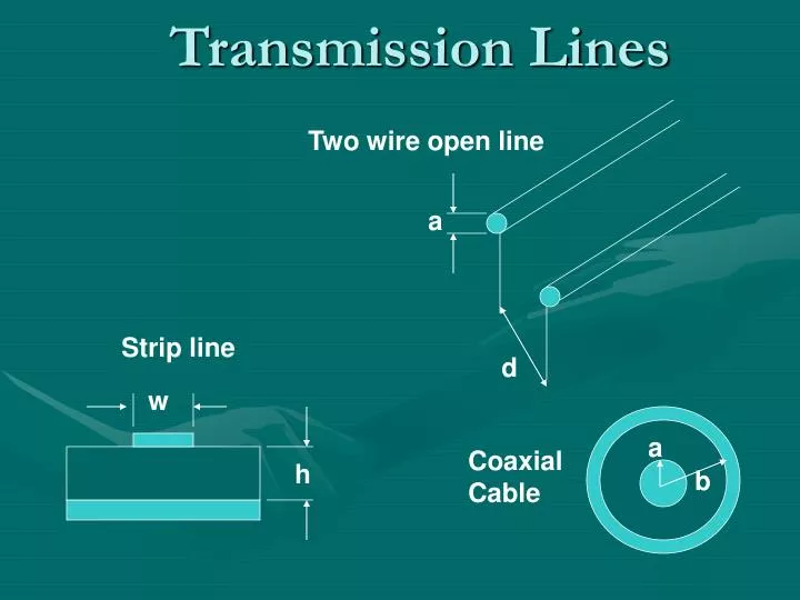
Two wire open line. Transmission Lines. a. Strip line. d. w. a. Coaxial Cable. h. b. Transmission. Two wire open line. The field distribution due to a pair of wires. Two wire open line. Line Behavior. When the switch is closed how long does the lamp take before it lights?.
Share Presentation
- magnetic energy
- energy input
- wire open line
- energy input vi watts

Presentation Transcript
Two wire open line Transmission Lines a Strip line d w a Coaxial Cable h b
Transmission
Two wire open line The field distribution due to a pair of wires
Two wire open line Line Behavior When the switch is closed how long does the lamp take before it lights? If we make it easy and let the length of the wires between battery and lamp be 3.108 m, then the time between the switch closing and lamp lighting will be approximately ______s.
Does this mean that electrons are traveling at the speed of light? Does it mean that the mechanism relies on electromagnetic energy being transported from start to finish of the structure? If so where is the energy stored during transit? If it is electromagnetic energy that is stored then it has to be stored in inductance for magnetic energy and capacitance for electric energy. This means that the transmission line has to have an inductance (per unit length) and a capacitance (per unit length). Two wire open line
Two wire open line Low Loss line at High Frequency Inductance and capacitance are uniformly and continuously distributed as L (Henrys/m) and C (Farads/m) respectively. When the switch is closed and a voltage V is applied to the line through a source impedance Zs, simple reasoning shows that the C's take a finite time to charge up through the L's; thus, the voltage propagates at a finite rate towards the load i.e. volts do not reach the load instantaneously.
Transmission in Capacitive Element Let L and C be distributed inductance and capacitance per unit length. In time t, electric flux q = (C ·x)v (from Q = CV) is produced in time x/u sec i(amps) = q/ t = Cx• v/ t (capacitive charging or "displacement" current) i = Cx• v /(x/ u ) = Cvu (I)
Transmission in Magnetic Element In time t, magnetic flux linkages =(L•x)i (from = LI) ; are produced in time x/u sec v(volts) = /t = L•x•i/t=Liu (ind Volts)…(II) Multiplying I and II:- vi =viCLu2 Or u = 1/ LC ms-1velocity of propagation Dividing I by II:- i/v =vC/iL or v2/i2 =L/C v/I = L/C……Characteristic Impedance Z0
Energy Transmission v2 L = ; i2 L = v2C i2 C ½ Li2 = ½ Cv2 Note:- the equality of Electric and Magnetic field energy in unit length of transmission line.
Movement of Energy Rate of energy input to line due to advance of wavefront, is vi watts. resistive load, connected directly to voltage source. Rate of energy input, due to thermal dissipation in R, is vi watts (also i2R).
Movement of Energy Rate of energy input = vi watts. Idea of a 'matched line': looks like an infinitely long line. Note: if Rg = Z0, maximum power if transferred from the generator to the line.
Movement of Energy As can be seen from the intuitive picture of a transmission line, wave propagation characteristics are dependent on the inductance and capacitance of the line. Thus we need to find expressions for the L and C of typical lines.
Inductance in Two wire line Inductance Assume r << S Due to conductor A, for 1 amp Linkages per metre, axially, L
Inductance in Two wire line Due to conductor B, an identical expression is Obtained:-
Mutual Inductance Between 2 Twin Lines External field due to 1 amp in line A, at radius
Mutual Inductance Between 2 Twin Lines Flux linkages per metre axially through circuit (between conductor 1 & 2) is:- = B =
Capacitance two wire line Capacitance of a Twin Line (r << S) Assign a line charge of 1 C/m to both conductors. D at x from conductor A is;
Capacitance two wire line and Similarly for VB(=VA)
R, L, C of Two wire line per unit length Rdc= ohm/m 2A2 0 d loge loge L = H/m a 0 C = F/m loge (d/a)
Z0Twin-wire line Characteristic Impedence For air, therefore Z0 = 120 loge(b/a), (approx ) 0 d loge L = a 0 C = loge (d/a)
- More by User

CENG4480_A4 Transmission lines
CENG4480_A4 Transmission lines. Transmission lines overview. (1) Characteristics of and applications of Transmission lines (3) Reflections in transmission lines and methods to reduce them Appendix1 Mathematics of transmission lines.
1.18k views • 58 slides
Transmission Lines. Lecture 10. Types of transmission lines. Open-wire transmission line
7.61k views • 46 slides

Transmission Lines. Dr. Sandra Cruz-Pol ECE Dept. UPRM. I in. + V L -. + V in -. Z g. Z o =30+j60 g=a +j b. Z L. V g. 40 m. Exercise 11.3.
2.74k views • 74 slides
Transmission Lines. Transmission Lines. Cross-sectional view of typical transmission lines (a) coaxial line, (b) two-wire line, (c) planar line, (d) wire above conducting plane, (e) microstrip line.
1.04k views • 33 slides

Transmission Lines ……..
Transmission Lines ……. Conductor Material Utility companies use different conductor materials for different applications. Copper, aluminum, and steel are the primary types of conductor materials used in electrical power systems.
805 views • 20 slides

2014 Transmission & Distribution Benchmarking Data Review Conference. Transmission Lines. June 24-27 , 2014 Nashville, TN. Agenda. Picture source: www.energy.gov. Introduction Statistics and System Activity Financial Initiatives and Practices Next Steps.
871 views • 58 slides
ELECTROMAGNETICS – TRANSMISSION LINES
Electrical Engineering 3 ELECTROMAGNETICS: Transmission Lines Dr. P.J.S. Ewen. ELECTROMAGNETICS – TRANSMISSION LINES Arrangements are same as for Prof. Murray's part of the course: Lectures: Tuesdays 9.00 – 9.50 LT 2
1.58k views • 36 slides

Transmission Lines. Animation Links. http://www.ee.ust.hk/eee/course/elec241/java/refwave1.html. http://www.ee.ust.hk/eee/course/elec241/java/refwave5.html. http://www.photonics.ece.mcgill.ca/courses/304-352/tl_anims_harmonic.html.
534 views • 37 slides

TRANSMISSION LINES
TRANSMISSION LINES. -- Bhanu Bhushan -- (April, 2011). R, L, C. Power loss, Thermal MVA capacity, Expansion, Sag, Corona Voltage drop, Power angle, Stability limit Charging current, Ferranti effect. Typical parameters for a 400 kV twin - Moose line, per km.
275 views • 4 slides

Transmission Lines. 1. Figure 11.1 Typical transmission lines in cross-sectional view: (a) coaxial line, (b) two-wire line, (c) planar line, (d) wire above conducting plane, (e) microstrip line.
1.38k views • 59 slides

12. Transmission Lines. Types of Transmission Lines. Two-Wire Open Line Transmission line between antenna and transmitter or antenna and receiver. Simple construction. Twisted Pair Two insulated wires twisted to form flexible line without use of spacers. Types of Transmission Lines.
1.39k views • 38 slides

Transmission Lines. Dr. Sandra Cruz-Pol ECE Dept. UPRM. I in. + V L -. + V in -. Z g. Z o =30+j60 g=a +j b. Z L. V g. 40 m. We ’ ll solve this problem later, but look at V in and V L. Exercise 11.3.
2.67k views • 85 slides

TRANSMISSION LINES. Chuck G0MDK. MYSTERY GUEST. Does any one recognize this Gentleman?. TRANSMISSION LINE TYPES. TWISTED PAIR TRANSMISSION LINE. Characteristic impedance 100 – 125 ohms Used primarily in telephone circuits It was never intended for RF use
747 views • 25 slides

Transmission Lines. Transmission line effects must be considered when length is comparable to ¼ wavelength We will ignore the energy loss on transmission lines Concentrate on time-domain description rather than frequency domain. i. z g. +. z l. e g. e. -. i. x. d. l.
880 views • 20 slides

Two wire open line. Transmission Lines. a. Strip line. d. w. a. Coaxial Cable. h. b. Two Wire Open Line. E x = E 0 exp (i[kz - t]), H y = (E 0 /Z 0 ) exp (i[kz- t]).
594 views • 24 slides

Transmission lines
Transmission lines. Outline. Types of transmission lines parallel conductors coaxial cables transmission line wave propagation Losses characteristics impedance incident and reflected wave and impedance matching. transmission media. Guided
1.24k views • 34 slides

Transmission Lines. Chris Allen ([email protected]) Course website URL people.eecs.ku.edu/~callen/713/EECS713.htm. Transmission lines. Used to transmit signals point-to-point Requirements
538 views • 35 slides

2014 Transmission & Distribution Benchmarking Insights Conference. Transmission Lines. August 20-22, 2014 Vail , CO. Agenda. Picture source: www.energy.gov. Introduction Statistics and System Activity Financial Initiatives and Practices. Key benchmarking Issues in Transmission.
1.63k views • 68 slides

Pioneer Power Systems specialists have extensive knowledge and experience in designing power transmission lines and electrical substations, as well as construction management during the installation of overhead transmission lines and underground power cables. For more details, visit this link: http://www.pioneerpowersystems.in/transmission-lines-2/
234 views • 1 slides

862 views • 59 slides

486 views • 34 slides

931 views • 6 slides

IMAGES
VIDEO
COMMENTS
transmission-lines. This document discusses transmission line theory and analysis. It begins by explaining how power is delivered through wires at low frequencies versus through electric and magnetic fields at microwave frequencies, defining transmission lines. It then lists common types of transmission lines including two-wire, coaxial cable ...
Power flow in a transmission line The real power input to a 3-phase transmission line can be computed as (9.43.1) where VS is the magnitude of the source (input) line-to-neutral voltage and VLL,S is the magnitude of the source (input) line-to-line voltage. Note that Y-connection is assumed!
Signal must be considered a wave propagating down line. Voilà, you have a transmission line. Rule of thumb: Treat cable, wire, or PCB trace as transmission line if length > λ/10 for highest frequency of interest. Must consider harmonics (rise/fall time), not just fundamental. Applies to digital as well as analog signals. Z. L T = 1/f ...
Lecture 1. General definition. General Definition Power transfer (e.g. for lighting, heating, performing work) - examples are mains electricity, microwave guides in a microwave oven, a fibre-optic illuminator. • A transmission line • is a device for propagating or guiding electromagnetic energy from one point to another.
Cross-sectional view of typical transmission lines (a) coaxial line, (b) two-wire line, (c) planar line, (d) wire above conducting plane, (e) microstrip line. (a) Coaxial line connecting the generator to the load; (b) E. and . H. fields on the coaxial line (TEM field structure). Transmission Lines. A.c. source
Guided Waves. So far in the course you have been dealing with waves that propagated in infinite size media. For many applications it is desirable to have electromagnetic energy be guided in much the same way as water flow is guided by having it flow in pipes. Transmission lines are the simplest structures that guide electromagnetic waves.
11.1 Transmission Line Theory. Figure 11.1: Transmission lines were the rst electromagnetic waveguides ever invented. The were driven by the needs in telegraphy technology. It is best to introduce transmission line theory from the viewpoint of circuit theory. This theory is also discussed in many textbooks and lecture 101.
Presentation Transcript. classifications of transmission lines • Balanced Transmission line • 2 wire balanced line. • both conductors carry current. But only one conductor carry signals. parallel conductors • consists of two or more metallic conductors (copper) • separated by insulator - air, rubber etc.
In this set of notes we develop some general formulas that hold for any transmission line. We first examine the coaxial cable as an example. Overview. Coaxial Cable. Here we present a "case study" of one particular transmission line, the coaxial cable. Find C, L, G, R. We will assume no variation in the. z. direction, and take a length of ...
Transmission Line Theory. Description: At microwave frequencies, such treatment of circuit elements is not possible since voltag and current waves do not affect the entire circuit at the same time. - PowerPoint PPT presentation. Number of Views: 507. Avg rating:3.0/5.0.
Pitch your topic with ease and precision using this power transmission tower with electric lines ppt powerpoint presentation pictures templates pdf. This layout presents information on power transmission tower with electric lines. It is also available for immediate download and adjustment.
Presentation Transcript. The Transmission Lines • Definition: • Structures used to transmit energy or signal in the form of guided-wave electromagnetic fields from one place to another • Modeling: • Distributed-element model • Electromagnetic model • Key Concepts: • Waves and properties. Different Types of Transmission Lines.
both ends and the load draws power from the Transmission Line. Performance. There are three types of losses in Transmission Line, 1. Ohmic Losses 2. Corona Loss 3. Loss due to leakage current Efficiency. ... PowerPoint Presentation Author: LED Created Date: 10/19/2020 8:05:01 PM ...
32 Best Transmission Lines-Themed Templates. CrystalGraphics creates templates designed to make even average presentations look incredible. Below you'll see thumbnail sized previews of the title slides of a few of our 32 best transmission lines templates for PowerPoint and Google Slides. The text you'll see in in those slides is just ...
Presentation Transcript. Transmission Lines Lecture 10. Types of transmission lines • Open-wire transmission line This simply consists of two parallel wires,closely spaced and separated by air. Nonconductive spacers are used to keep the distance between the two wires constant. The distance between the wires is between 2 and 6 inches.
Pitch your topic with ease and precision using this power transmission tower with electric lines ppt powerpoint presentation pictures templates pdf. This layout presents information on power transmission tower with electric lines. It is also available for immediate download and adjustment. So, changes can be made in the color, design, graphics ...
Two Segment Transmission Line Structures Transmission Lines Class 6. Assignment • Consider the two segment transmission line shown to the right. Assume RS= 3Z01 and Z02= 3Z01 /3. Use Lattice diagram and calculate reflection coefficients at the interfaces and show the wave forms of V1 (t),V2 (t), and V3 (t).
CrystalGraphics creates templates designed to make even average presentations look incredible. Below you'll see thumbnail sized previews of the title slides of a few of our 17 best power transmission line templates for PowerPoint and Google Slides. The text you'll see in in those slides is just example text. The power transmission line ...
This means that the transmission line has to have an inductance (per unit length) and a capacitance (per unit length). Two wire open line. Two wire open line Low Loss line at High Frequency Inductance and capacitance are uniformly and continuously distributed as L (Henrys/m) and C (Farads/m) respectively.