5.1 Vector Addition and Subtraction: Graphical Methods
Section learning objectives.
By the end of this section, you will be able to do the following:
- Describe the graphical method of vector addition and subtraction
- Use the graphical method of vector addition and subtraction to solve physics problems

Teacher Support
The learning objectives in this section will help your students master the following standards:
- (E) develop and interpret free-body force diagrams.
Section Key Terms
The graphical method of vector addition and subtraction.
Recall that a vector is a quantity that has magnitude and direction. For example, displacement, velocity, acceleration, and force are all vectors. In one-dimensional or straight-line motion, the direction of a vector can be given simply by a plus or minus sign. Motion that is forward, to the right, or upward is usually considered to be positive (+); and motion that is backward, to the left, or downward is usually considered to be negative (−).
In two dimensions, a vector describes motion in two perpendicular directions, such as vertical and horizontal. For vertical and horizontal motion, each vector is made up of vertical and horizontal components. In a one-dimensional problem, one of the components simply has a value of zero. For two-dimensional vectors, we work with vectors by using a frame of reference such as a coordinate system. Just as with one-dimensional vectors, we graphically represent vectors with an arrow having a length proportional to the vector’s magnitude and pointing in the direction that the vector points.
[BL] [OL] Review vectors and free body diagrams. Recall how velocity, displacement and acceleration vectors are represented.
Figure 5.2 shows a graphical representation of a vector; the total displacement for a person walking in a city. The person first walks nine blocks east and then five blocks north. Her total displacement does not match her path to her final destination. The displacement simply connects her starting point with her ending point using a straight line, which is the shortest distance. We use the notation that a boldface symbol, such as D , stands for a vector. Its magnitude is represented by the symbol in italics, D , and its direction is given by an angle represented by the symbol θ . θ . Note that her displacement would be the same if she had begun by first walking five blocks north and then walking nine blocks east.
Tips For Success
In this text, we represent a vector with a boldface variable. For example, we represent a force with the vector F , which has both magnitude and direction. The magnitude of the vector is represented by the variable in italics, F , and the direction of the variable is given by the angle θ . θ .
The head-to-tail method is a graphical way to add vectors. The tail of the vector is the starting point of the vector, and the head (or tip) of a vector is the pointed end of the arrow. The following steps describe how to use the head-to-tail method for graphical vector addition .
- If there are more than two vectors, continue to add the vectors head-to-tail as described in step 2. In this example, we have only two vectors, so we have finished placing arrows tip to tail.
- To find the magnitude of the resultant, measure its length with a ruler. When we deal with vectors analytically in the next section, the magnitude will be calculated by using the Pythagorean theorem.
- To find the direction of the resultant, use a protractor to measure the angle it makes with the reference direction (in this case, the x -axis). When we deal with vectors analytically in the next section, the direction will be calculated by using trigonometry to find the angle.
[AL] Ask two students to demonstrate pushing a table from two different directions. Ask students what they feel the direction of resultant motion will be. How would they represent this graphically? Recall that a vector’s magnitude is represented by the length of the arrow. Demonstrate the head-to-tail method of adding vectors, using the example given in the chapter. Ask students to practice this method of addition using a scale and a protractor.
[BL] [OL] [AL] Ask students if anything changes by moving the vector from one place to another on a graph. How about the order of addition? Would that make a difference? Introduce negative of a vector and vector subtraction.
Watch Physics
Visualizing vector addition examples.
This video shows four graphical representations of vector addition and matches them to the correct vector addition formula.
- Yes, if we add the same two vectors in a different order it will still give the same resultant vector.
- No, the resultant vector will change if we add the same vectors in a different order.
Vector subtraction is done in the same way as vector addition with one small change. We add the first vector to the negative of the vector that needs to be subtracted. A negative vector has the same magnitude as the original vector, but points in the opposite direction (as shown in Figure 5.6 ). Subtracting the vector B from the vector A , which is written as A − B , is the same as A + (− B ). Since it does not matter in what order vectors are added, A − B is also equal to (− B ) + A . This is true for scalars as well as vectors. For example, 5 – 2 = 5 + (−2) = (−2) + 5.
Global angles are calculated in the counterclockwise direction. The clockwise direction is considered negative. For example, an angle of 30 ∘ 30 ∘ south of west is the same as the global angle 210 ∘ , 210 ∘ , which can also be expressed as −150 ∘ −150 ∘ from the positive x -axis.
Using the Graphical Method of Vector Addition and Subtraction to Solve Physics Problems
Now that we have the skills to work with vectors in two dimensions, we can apply vector addition to graphically determine the resultant vector , which represents the total force. Consider an example of force involving two ice skaters pushing a third as seen in Figure 5.7 .
In problems where variables such as force are already known, the forces can be represented by making the length of the vectors proportional to the magnitudes of the forces. For this, you need to create a scale. For example, each centimeter of vector length could represent 50 N worth of force. Once you have the initial vectors drawn to scale, you can then use the head-to-tail method to draw the resultant vector. The length of the resultant can then be measured and converted back to the original units using the scale you created.
You can tell by looking at the vectors in the free-body diagram in Figure 5.7 that the two skaters are pushing on the third skater with equal-magnitude forces, since the length of their force vectors are the same. Note, however, that the forces are not equal because they act in different directions. If, for example, each force had a magnitude of 400 N, then we would find the magnitude of the total external force acting on the third skater by finding the magnitude of the resultant vector. Since the forces act at a right angle to one another, we can use the Pythagorean theorem. For a triangle with sides a, b, and c, the Pythagorean theorem tells us that
Applying this theorem to the triangle made by F 1 , F 2 , and F tot in Figure 5.7 , we get
Note that, if the vectors were not at a right angle to each other ( 90 ∘ ( 90 ∘ to one another), we would not be able to use the Pythagorean theorem to find the magnitude of the resultant vector. Another scenario where adding two-dimensional vectors is necessary is for velocity, where the direction may not be purely east-west or north-south, but some combination of these two directions. In the next section, we cover how to solve this type of problem analytically. For now let’s consider the problem graphically.
Worked Example
Adding vectors graphically by using the head-to-tail method: a woman takes a walk.
Use the graphical technique for adding vectors to find the total displacement of a person who walks the following three paths (displacements) on a flat field. First, she walks 25 m in a direction 49 ∘ 49 ∘ north of east. Then, she walks 23 m heading 15 ∘ 15 ∘ north of east. Finally, she turns and walks 32 m in a direction 68 ∘ 68 ∘ south of east.
Graphically represent each displacement vector with an arrow, labeling the first A , the second B , and the third C . Make the lengths proportional to the distance of the given displacement and orient the arrows as specified relative to an east-west line. Use the head-to-tail method outlined above to determine the magnitude and direction of the resultant displacement, which we’ll call R .
(1) Draw the three displacement vectors, creating a convenient scale (such as 1 cm of vector length on paper equals 1 m in the problem), as shown in Figure 5.8 .
(2) Place the vectors head to tail, making sure not to change their magnitude or direction, as shown in Figure 5.9 .
(3) Draw the resultant vector R from the tail of the first vector to the head of the last vector, as shown in Figure 5.10 .
(4) Use a ruler to measure the magnitude of R , remembering to convert back to the units of meters using the scale. Use a protractor to measure the direction of R . While the direction of the vector can be specified in many ways, the easiest way is to measure the angle between the vector and the nearest horizontal or vertical axis. Since R is south of the eastward pointing axis (the x -axis), we flip the protractor upside down and measure the angle between the eastward axis and the vector, as illustrated in Figure 5.11 .
In this case, the total displacement R has a magnitude of 50 m and points 7 ∘ 7 ∘ south of east. Using its magnitude and direction, this vector can be expressed as
The head-to-tail graphical method of vector addition works for any number of vectors. It is also important to note that it does not matter in what order the vectors are added. Changing the order does not change the resultant. For example, we could add the vectors as shown in Figure 5.12 , and we would still get the same solution.
[BL] [OL] [AL] Ask three students to enact the situation shown in Figure 5.8 . Recall how these forces can be represented in a free-body diagram. Giving values to these vectors, show how these can be added graphically.
Subtracting Vectors Graphically: A Woman Sailing a Boat
A woman sailing a boat at night is following directions to a dock. The instructions read to first sail 27.5 m in a direction 66.0 ∘ 66.0 ∘ north of east from her current location, and then travel 30.0 m in a direction 112 ∘ 112 ∘ north of east (or 22.0 ∘ 22.0 ∘ west of north). If the woman makes a mistake and travels in the opposite direction for the second leg of the trip, where will she end up? The two legs of the woman’s trip are illustrated in Figure 5.13 .
We can represent the first leg of the trip with a vector A , and the second leg of the trip that she was supposed to take with a vector B . Since the woman mistakenly travels in the opposite direction for the second leg of the journey, the vector for second leg of the trip she actually takes is − B . Therefore, she will end up at a location A + (− B ), or A − B . Note that − B has the same magnitude as B (30.0 m), but is in the opposite direction, 68 ∘ ( 180 ∘ − 112 ∘ ) 68 ∘ ( 180 ∘ − 112 ∘ ) south of east, as illustrated in Figure 5.14 .
We use graphical vector addition to find where the woman arrives A + (− B ).
(1) To determine the location at which the woman arrives by accident, draw vectors A and − B .
(2) Place the vectors head to tail.
(3) Draw the resultant vector R .
(4) Use a ruler and protractor to measure the magnitude and direction of R .
These steps are demonstrated in Figure 5.15 .
In this case
Because subtraction of a vector is the same as addition of the same vector with the opposite direction, the graphical method for subtracting vectors works the same as for adding vectors.
Adding Velocities: A Boat on a River
A boat attempts to travel straight across a river at a speed of 3.8 m/s. The river current flows at a speed v river of 6.1 m/s to the right. What is the total velocity and direction of the boat? You can represent each meter per second of velocity as one centimeter of vector length in your drawing.
We start by choosing a coordinate system with its x-axis parallel to the velocity of the river. Because the boat is directed straight toward the other shore, its velocity is perpendicular to the velocity of the river. We draw the two vectors, v boat and v river , as shown in Figure 5.16 .
Using the head-to-tail method, we draw the resulting total velocity vector from the tail of v boat to the head of v river .
By using a ruler, we find that the length of the resultant vector is 7.2 cm, which means that the magnitude of the total velocity is
By using a protractor to measure the angle, we find θ = 32.0 ∘ . θ = 32.0 ∘ .
If the velocity of the boat and river were equal, then the direction of the total velocity would have been 45°. However, since the velocity of the river is greater than that of the boat, the direction is less than 45° with respect to the shore, or x axis.
Teacher Demonstration
Plot the way from the classroom to the cafeteria (or any two places in the school on the same level). Ask students to come up with approximate distances. Ask them to do a vector analysis of the path. What is the total distance travelled? What is the displacement?
Practice Problems
Virtual physics, vector addition.
In this simulation , you will experiment with adding vectors graphically. Click and drag the red vectors from the Grab One basket onto the graph in the middle of the screen. These red vectors can be rotated, stretched, or repositioned by clicking and dragging with your mouse. Check the Show Sum box to display the resultant vector (in green), which is the sum of all of the red vectors placed on the graph. To remove a red vector, drag it to the trash or click the Clear All button if you wish to start over. Notice that, if you click on any of the vectors, the | R | | R | is its magnitude, θ θ is its direction with respect to the positive x -axis, R x is its horizontal component, and R y is its vertical component. You can check the resultant by lining up the vectors so that the head of the first vector touches the tail of the second. Continue until all of the vectors are aligned together head-to-tail. You will see that the resultant magnitude and angle is the same as the arrow drawn from the tail of the first vector to the head of the last vector. Rearrange the vectors in any order head-to-tail and compare. The resultant will always be the same.
Grasp Check
True or False—The more long, red vectors you put on the graph, rotated in any direction, the greater the magnitude of the resultant green vector.
Check Your Understanding
- backward and to the left
- backward and to the right
- forward and to the right
- forward and to the left
True or False—A person walks 2 blocks east and 5 blocks north. Another person walks 5 blocks north and then two blocks east. The displacement of the first person will be more than the displacement of the second person.
Use the Check Your Understanding questions to assess whether students achieve the learning objectives for this section. If students are struggling with a specific objective, the Check Your Understanding will help identify which objective is causing the problem and direct students to the relevant content.
As an Amazon Associate we earn from qualifying purchases.
This book may not be used in the training of large language models or otherwise be ingested into large language models or generative AI offerings without OpenStax's permission.
Want to cite, share, or modify this book? This book uses the Creative Commons Attribution License and you must attribute Texas Education Agency (TEA). The original material is available at: https://www.texasgateway.org/book/tea-physics . Changes were made to the original material, including updates to art, structure, and other content updates.
Access for free at https://openstax.org/books/physics/pages/1-introduction
- Authors: Paul Peter Urone, Roger Hinrichs
- Publisher/website: OpenStax
- Book title: Physics
- Publication date: Mar 26, 2020
- Location: Houston, Texas
- Book URL: https://openstax.org/books/physics/pages/1-introduction
- Section URL: https://openstax.org/books/physics/pages/5-1-vector-addition-and-subtraction-graphical-methods
© Jan 19, 2024 Texas Education Agency (TEA). The OpenStax name, OpenStax logo, OpenStax book covers, OpenStax CNX name, and OpenStax CNX logo are not subject to the Creative Commons license and may not be reproduced without the prior and express written consent of Rice University.
- Graphical Representation of Motion
Graphical Representation makes it simpler for us to understand data. When analyzing motion, graphs representing values of various parameters of motion make it simpler to solve problems. Let us understand the concept of motion and the other entities related to it using the graphical method.
Suggested Videos
Using a graph for a pictorial representation of two sets of data is called a graphical representation of data . One entity is represented on the x-axis of the graph while the other is represented on the y-axis. Out of the two entities, one is a dependent set of variables while the other is independent an independent set of variables.
We use line graphs to describe the motion of an object. This graph shows the dependency of a physical quantity speed or distance on another quantity, for example, time.
Browse more Topics under Motion
- Introduction to Motion and its Parameters
- Equations of Motion
- Uniform Circular Motion
Distance Time Graph
The distance-time graph determines the change in the position of the object. The speed of the object as well can be determined using the line graph. Here the time lies on the x-axis while the distance on the y-axis. Remember, the line graph of uniform motion is always a straight line .
Why? Because as the definition goes, uniform motion is when an object covers the equal amount of distance at equal intervals of time. Hence the straight line. While the graph of a non-uniform motion is a curved graph.
Velocity and Time Graph

A velocity-time graph is also a straight line. Here the time is on the x-axis while the velocity is on the y-axis. The product of time and velocity gives the displacement of an object moving at a uniform speed. The velocity of time and graph of a velocity that changes uniformly is a straight line. We can use this graph to calculate the acceleration of the object.
Acceleration =(Change in velocity)/time
For calculating acceleration draw a perpendicular on the x-axis from the graph point as shown in the figure. Here the acceleration will be equal to the slope of the velocity-time graph. Distance travelled will be equal to the area of the triangle, Therefore,
Distance traveled= (Base × Height)/2
Just like in the distance-time graph, when the velocity is non-uniform the velocity-time graph is a curved line.
Solved Examples for You
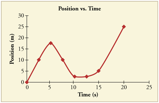
Question: The graph shows position as a function of time for an object moving along a straight line. During which time(s) is the object at rest?
- 0.5 seconds
- From 1 to 2 seconds
- 2.5 seconds

Solution: Option B. Slope of the curve under the position-time graph gives the instantaneous velocity of the object. The slope of the curve is zero only in the time interval 1 < t < 2 s. Thus the object is at rest (or velocity is zero) only from 1 to 2 s. Hence option B is correct.
Customize your course in 30 seconds
Which class are you in.

- Impending Motion
- Transportation History
- Acceleration
- Force And Motion
- Introduction to Motion and Its Parameters
Leave a Reply Cancel reply
Your email address will not be published. Required fields are marked *
Download the App


Want to create or adapt books like this? Learn more about how Pressbooks supports open publishing practices.
25 Graphical Analysis of One-Dimensional Motion
[latexpage]
Learning Objectives
- Describe a straight-line graph in terms of its slope and y -intercept.
- Determine average velocity or instantaneous velocity from a graph of position vs. time.
- Determine average or instantaneous acceleration from a graph of velocity vs. time.
- Derive a graph of velocity vs. time from a graph of position vs. time.
- Derive a graph of acceleration vs. time from a graph of velocity vs. time.
A graph, like a picture, is worth a thousand words. Graphs not only contain numerical information; they also reveal relationships between physical quantities. This section uses graphs of position, velocity, and acceleration versus time to illustrate one-dimensional kinematics.
Slopes and General Relationships
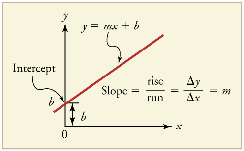
First note that graphs in this text have perpendicular axes, one horizontal and the other vertical. When two physical quantities are plotted against one another in such a graph, the horizontal axis is usually considered to be an independent variable and the vertical axis a dependent variable . If we call the horizontal axis the \(x\)-axis and the vertical axis the \(y\)-axis, as in (Figure) , a straight-line graph has the general form
Here \(m\) is the slope , defined to be the rise divided by the run (as seen in the figure) of the straight line. The letter \(b\) is used for the y -intercept , which is the point at which the line crosses the vertical axis.
Graph of Position vs. Time ( a = 0, so v is constant)
Time is usually an independent variable that other quantities, such as position, depend upon. A graph of position versus time would, thus, have \(x\) on the vertical axis and \(t\) on the horizontal axis. (Figure) is just such a straight-line graph. It shows a graph of position versus time for a jet-powered car on a very flat dry lake bed in Nevada.
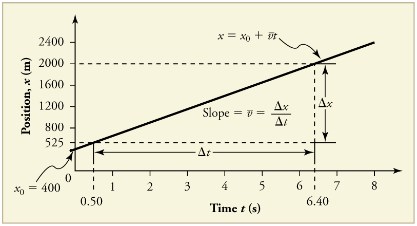
Using the relationship between dependent and independent variables, we see that the slope in the graph above is average velocity \(\stackrel{-}{v}\) and the intercept is position at time zero—that is, \({x}_{0}\). Substituting these symbols into \(y=\text{mx}+b\) gives
Thus a graph of position versus time gives a general relationship among displacement(change in position), velocity, and time, as well as giving detailed numerical information about a specific situation.
The slope of the graph of position \(x\) vs. time \(t\) is velocity \(v\).
Notice that this equation is the same as that derived algebraically from other motion equations in Motion Equations for Constant Acceleration in One Dimension .
From the figure we can see that the car has a position of 525 m at 0.50 s and 2000 m at 6.40 s. Its position at other times can be read from the graph; furthermore, information about its velocity and acceleration can also be obtained from the graph.
Find the average velocity of the car whose position is graphed in (Figure) .
The slope of a graph of \(x\) vs. \(t\) is average velocity, since slope equals rise over run. In this case, rise = change in position and run = change in time, so that
Since the slope is constant here, any two points on the graph can be used to find the slope. (Generally speaking, it is most accurate to use two widely separated points on the straight line. This is because any error in reading data from the graph is proportionally smaller if the interval is larger.)
1. Choose two points on the line. In this case, we choose the points labeled on the graph: (6.4 s, 2000 m) and (0.50 s, 525 m). (Note, however, that you could choose any two points.)
2. Substitute the \(x\) and \(t\) values of the chosen points into the equation. Remember in calculating change \(\left(\Delta \right)\) we always use final value minus initial value.
This is an impressively large land speed (900 km/h, or about 560 mi/h): much greater than the typical highway speed limit of 60 mi/h (27 m/s or 96 km/h), but considerably shy of the record of 343 m/s (1234 km/h or 766 mi/h) set in 1997.
Graphs of Motion when \(a\) is constant but \(a\ne 0\)
The graphs in (Figure) below represent the motion of the jet-powered car as it accelerates toward its top speed, but only during the time when its acceleration is constant. Time starts at zero for this motion (as if measured with a stopwatch), and the position and velocity are initially 200 m and 15 m/s, respectively.
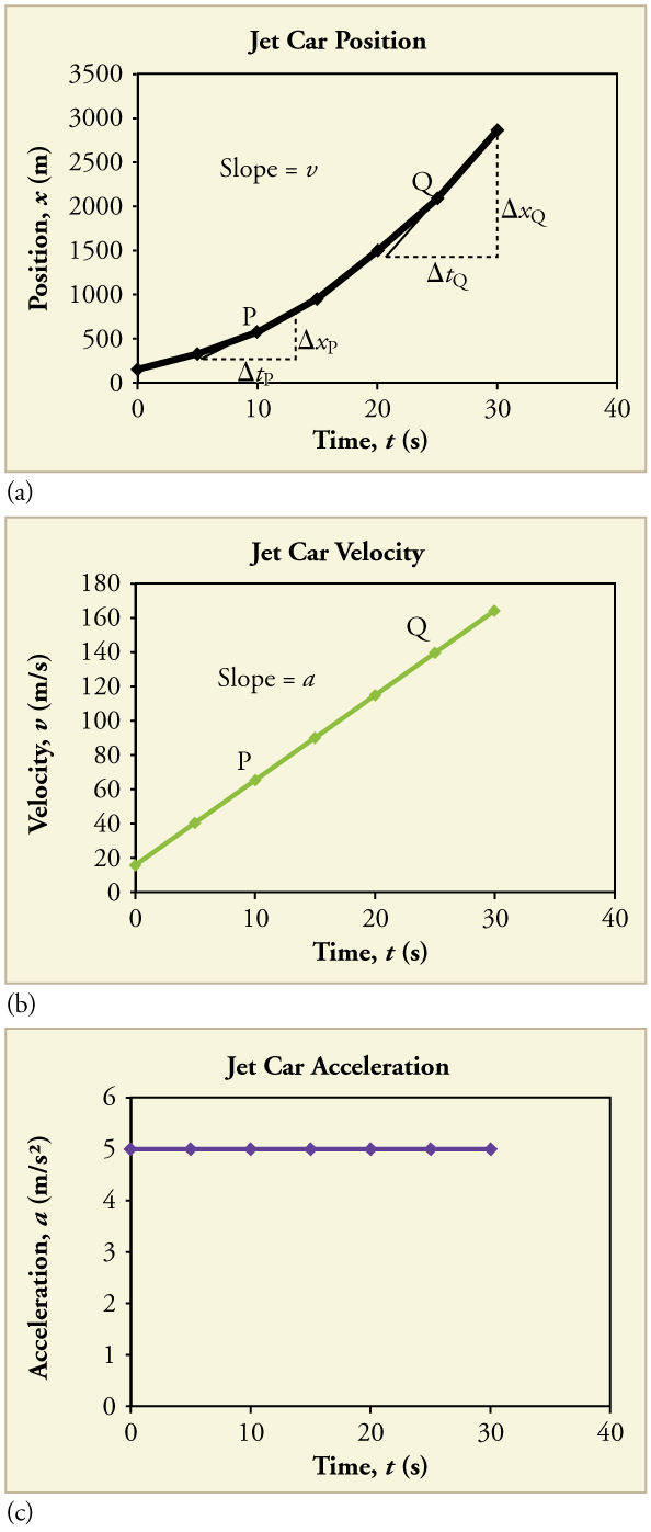
The graph of position versus time in (Figure) (a) is a curve rather than a straight line. The slope of the curve becomes steeper as time progresses, showing that the velocity is increasing over time. The slope at any point on a position-versus-time graph is the instantaneous velocity at that point. It is found by drawing a straight line tangent to the curve at the point of interest and taking the slope of this straight line. Tangent lines are shown for two points in (Figure) (a). If this is done at every point on the curve and the values are plotted against time, then the graph of velocity versus time shown in (Figure) (b) is obtained. Furthermore, the slope of the graph of velocity versus time is acceleration, which is shown in (Figure) (c).
Calculate the velocity of the jet car at a time of 25 s by finding the slope of the \(x\) vs. \(t\) graph in the graph below.
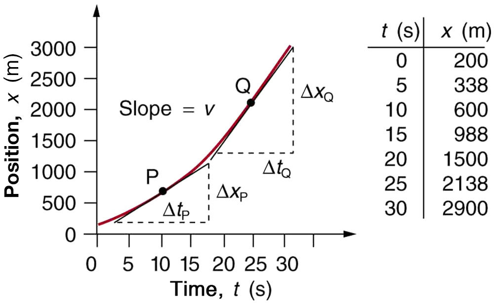
The slope of a curve at a point is equal to the slope of a straight line tangent to the curve at that point. This principle is illustrated in (Figure) , where Q is the point at \(t=\text{25 s}\).
1. Find the tangent line to the curve at \(t=\text{25 s}\).
2. Determine the endpoints of the tangent. These correspond to a position of 1300 m at time 19 s and a position of 3120 m at time 32 s.
3. Plug these endpoints into the equation to solve for the slope, \(v\) .
This is the value given in this figure’s table for \(v\) at \(t=\text{25 s}\). The value of 140 m/s for \({v}_{Q}\) is plotted in (Figure) . The entire graph of \(v\) vs. \(t\) can be obtained in this fashion.
Carrying this one step further, we note that the slope of a velocity versus time graph is acceleration. Slope is rise divided by run; on a \(v\) vs. \(t\) graph, rise = change in velocity \(\Delta v\) and run = change in time \(\Delta t\).
The slope of a graph of velocity \(v\) vs. time \(t\) is acceleration \(a\) .
Since the velocity versus time graph in (Figure) (b) is a straight line, its slope is the same everywhere, implying that acceleration is constant. Acceleration versus time is graphed in (Figure) (c).
Additional general information can be obtained from (Figure) and the expression for a straight line, \(y=\text{mx}+b\).
In this case, the vertical axis \(y\) is \(V\), the intercept \(b\) is \({v}_{0}\), the slope \(m\) is \(a\), and the horizontal axis \(x\) is \(t\). Substituting these symbols yields
A general relationship for velocity, acceleration, and time has again been obtained from a graph. Notice that this equation was also derived algebraically from other motion equations in Motion Equations for Constant Acceleration in One Dimension .
It is not accidental that the same equations are obtained by graphical analysis as by algebraic techniques. In fact, an important way to discover physical relationships is to measure various physical quantities and then make graphs of one quantity against another to see if they are correlated in any way. Correlations imply physical relationships and might be shown by smooth graphs such as those above. From such graphs, mathematical relationships can sometimes be postulated. Further experiments are then performed to determine the validity of the hypothesized relationships.
Graphs of Motion Where Acceleration is Not Constant
Now consider the motion of the jet car as it goes from 165 m/s to its top velocity of 250 m/s, graphed in (Figure) . Time again starts at zero, and the initial position and velocity are 2900 m and 165 m/s, respectively. (These were the final position and velocity of the car in the motion graphed in (Figure) .) Acceleration gradually decreases from \(5\text{.}{\text{0 m/s}}^{2}\) to zero when the car hits 250 m/s. The slope of the \(x\) vs. \(t\) graph increases until \(t=\text{55 s}\), after which time the slope is constant. Similarly, velocity increases until 55 s and then becomes constant, since acceleration decreases to zero at 55 s and remains zero afterward.
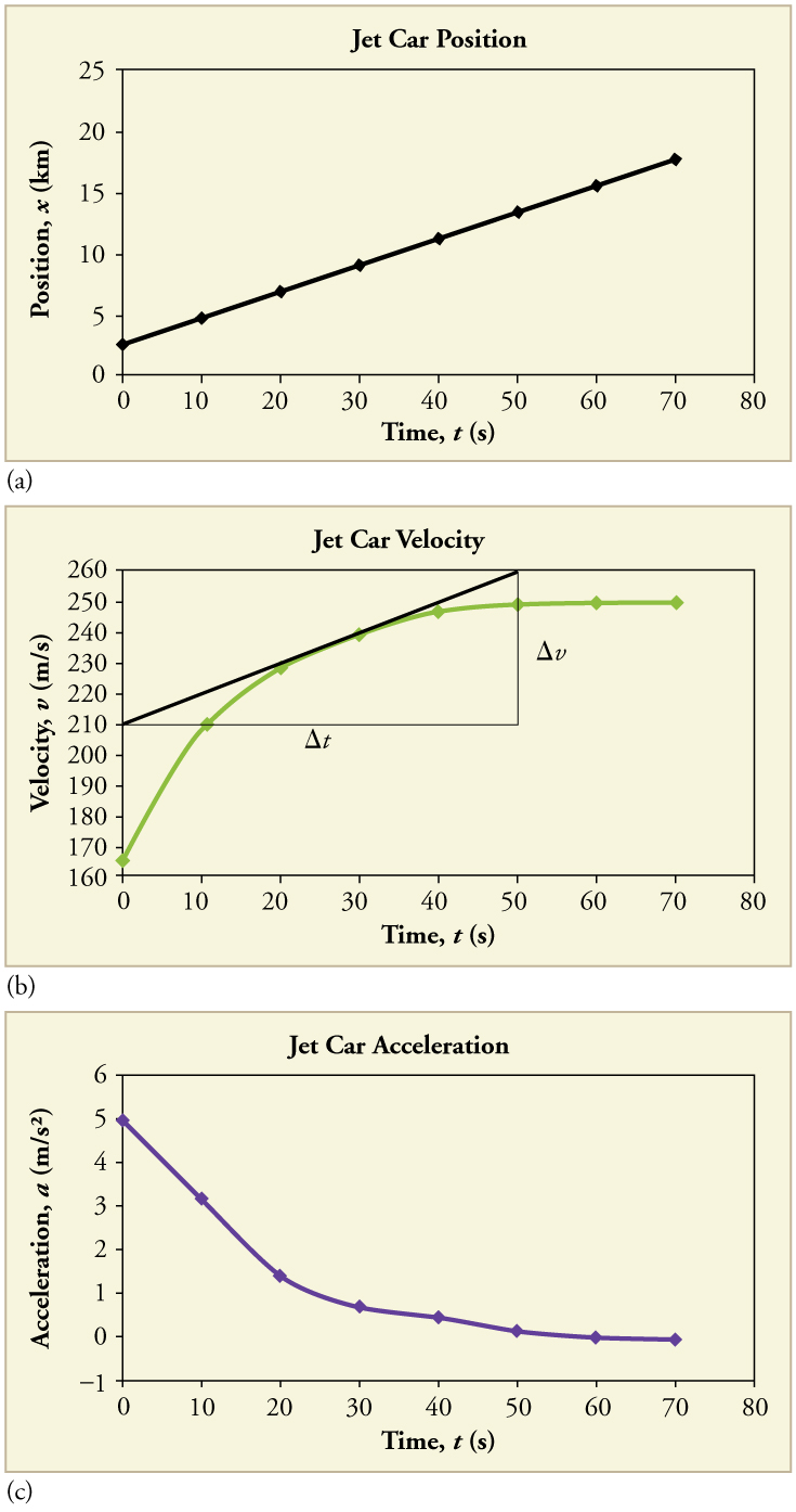
Calculate the acceleration of the jet car at a time of 25 s by finding the slope of the \(v\) vs. \(t\) graph in (Figure) (b).
The slope of the curve at \(t=\text{25 s}\) is equal to the slope of the line tangent at that point, as illustrated in (Figure) (b).
Determine endpoints of the tangent line from the figure, and then plug them into the equation to solve for slope, \(a\).
Note that this value for \(a\) is consistent with the value plotted in (Figure) (c) at \(t=\text{25 s}\).
A graph of position versus time can be used to generate a graph of velocity versus time, and a graph of velocity versus time can be used to generate a graph of acceleration versus time. We do this by finding the slope of the graphs at every point. If the graph is linear (i.e., a line with a constant slope), it is easy to find the slope at any point and you have the slope for every point. Graphical analysis of motion can be used to describe both specific and general characteristics of kinematics. Graphs can also be used for other topics in physics. An important aspect of exploring physical relationships is to graph them and look for underlying relationships.
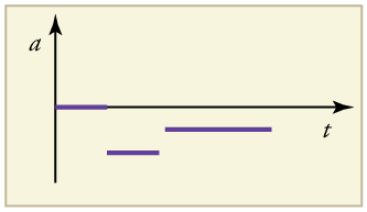
A graph of velocity vs. time of a ship coming into a harbor is shown below. (a) Describe the motion of the ship based on the graph. (b)What would a graph of the ship’s acceleration look like?
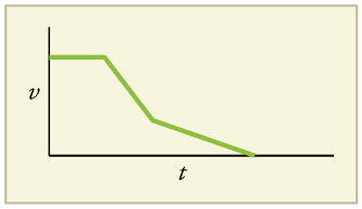
(a) The ship moves at constant velocity and then begins to decelerate at a constant rate. At some point, its deceleration rate decreases. It maintains this lower deceleration rate until it stops moving.
(b) A graph of acceleration vs. time would show zero acceleration in the first leg, large and constant negative acceleration in the second leg, and constant negative acceleration.
Section Summary
- Graphs of motion can be used to analyze motion.
- Graphical solutions yield identical solutions to mathematical methods for deriving motion equations.
- The slope of a graph of displacement \(x\) vs. time \(t\) is velocity \(v\) .
- The slope of a graph of velocity \(v\) vs. time \(t\) graph is acceleration \(a\) .
- Average velocity, instantaneous velocity, and acceleration can all be obtained by analyzing graphs.
Conceptual Questions
(a) Explain how you can use the graph of position versus time in (Figure) to describe the change in velocity over time. Identify (b) the time (\({t}_{a}\), \({t}_{b}\), \({t}_{c}\), \({t}_{d}\), or \({t}_{e}\)) at which the instantaneous velocity is greatest, (c) the time at which it is zero, and (d) the time at which it is negative.
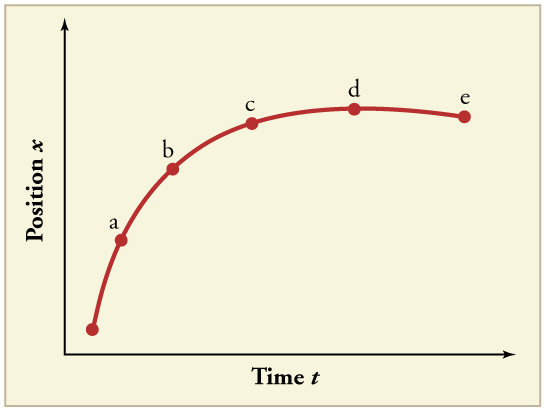
(a) Sketch a graph of velocity versus time corresponding to the graph of position versus time given in (Figure) . (b) Identify the time or times (\({t}_{a}\), \({t}_{b}\), \({t}_{c}\), etc.) at which the instantaneous velocity is greatest. (c) At which times is it zero? (d) At which times is it negative?
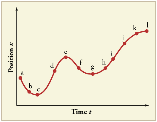
(a) Explain how you can determine the acceleration over time from a velocity versus time graph such as the one in (Figure) . (b) Based on the graph, how does acceleration change over time?
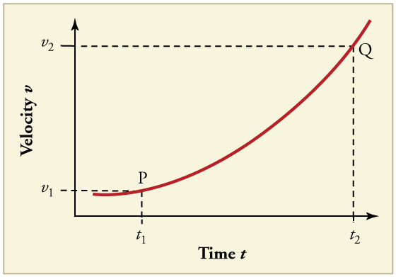
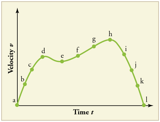
(a) Sketch a graph of acceleration versus time corresponding to the graph of velocity versus time given in (Figure) . (b) Identify the time or times (\({t}_{a}\), \({t}_{b}\), \({t}_{c}\), etc.) at which the acceleration is greatest. (c) At which times is it zero? (d) At which times is it negative?
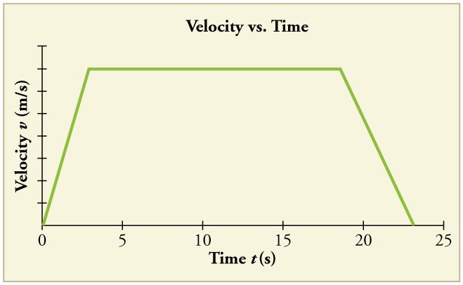
Consider the velocity vs. time graph of a person in an elevator shown in (Figure) . Suppose the elevator is initially at rest. It then accelerates for 3 seconds, maintains that velocity for 15 seconds, then decelerates for 5 seconds until it stops. The acceleration for the entire trip is not constant so we cannot use the equations of motion from Motion Equations for Constant Acceleration in One Dimension for the complete trip. (We could, however, use them in the three individual sections where acceleration is a constant.) Sketch graphs of (a) position vs. time and (b) acceleration vs. time for this trip.
A cylinder is given a push and then rolls up an inclined plane. If the origin is the starting point, sketch the position, velocity, and acceleration of the cylinder vs. time as it goes up and then down the plane.
Problems & Exercises
Note: There is always uncertainty in numbers taken from graphs. If your answers differ from expected values, examine them to see if they are within data extraction uncertainties estimated by you.
(a) By taking the slope of the curve in (Figure) , verify that the velocity of the jet car is 115 m/s at \(t=\text{20 s}\). (b) By taking the slope of the curve at any point in (Figure) , verify that the jet car’s acceleration is \(5\text{.}{\text{0 m/s}}^{2}\).
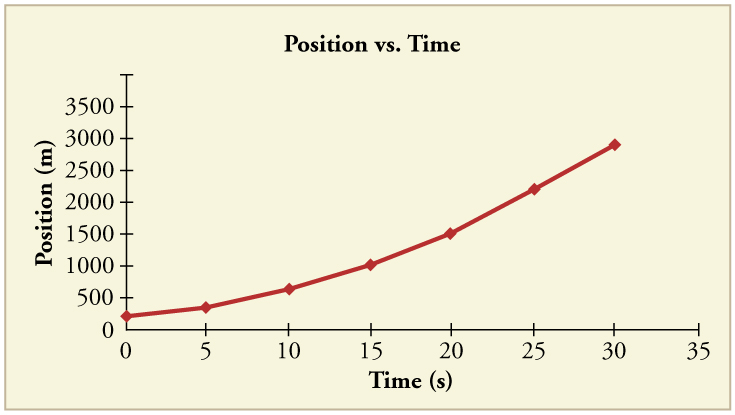
(a) \(\text{115 m/s}\)
(b) \(5\text{.}{\text{0 m/s}}^{2}\)
Using approximate values, calculate the slope of the curve in (Figure) to verify that the velocity at \(t=\text{10.0 s}\) is 0.208 m/s. Assume all values are known to 3 significant figures.
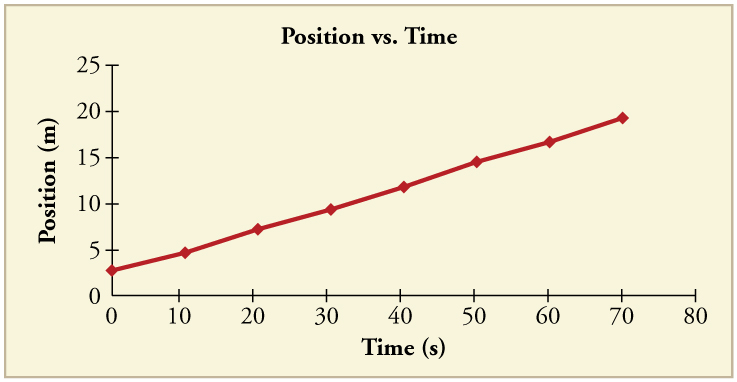
Using approximate values, calculate the slope of the curve in (Figure) to verify that the velocity at \(t=\text{30.0 s}\) is approximately 0.24 m/s.
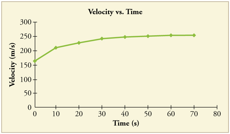
By taking the slope of the curve in (Figure) , verify that the acceleration is \(3\text{.}2 m{\text{/s}}^{2}\) at \(t=\text{10 s}\).
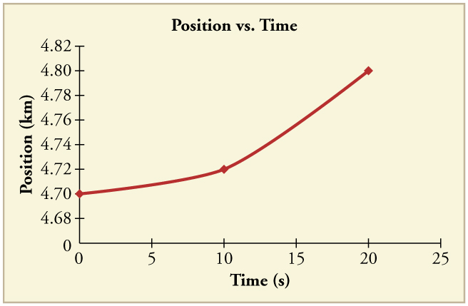
Construct the position graph for the subway shuttle train as shown in (Figure) (a). Your graph should show the position of the train, in kilometers, from t = 0 to 20 s. You will need to use the information on acceleration and velocity given in the examples for this figure.
(a) Take the slope of the curve in (Figure) to find the jogger’s velocity at \(t=2\text{.}5 s\). (b) Repeat at 7.5 s. These values must be consistent with the graph in (Figure) .
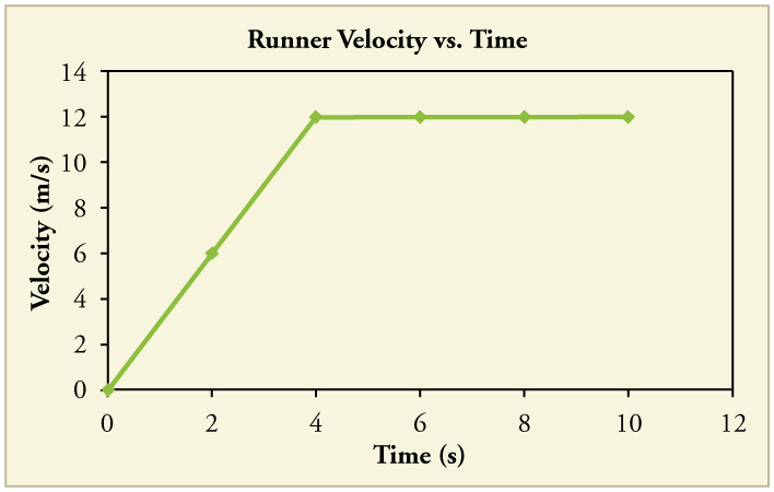
A graph of \(v\left(t\right)\) is shown for a world-class track sprinter in a 100-m race. (See (Figure) ). (a) What is his average velocity for the first 4 s? (b) What is his instantaneous velocity at \(t=5 s\)? (c) What is his average acceleration between 0 and 4 s? (d) What is his time for the race?
(c) \({\text{3 m/s}}^{2}\)
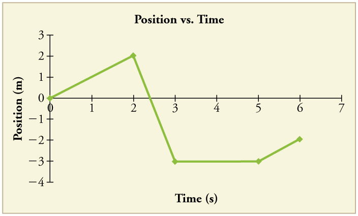
(Figure) shows the position graph for a particle for 5 s. Draw the corresponding velocity and acceleration graphs.
Intro to Physics for Non-Majors Copyright © 2012 by OSCRiceUniversity is licensed under a Creative Commons Attribution 4.0 International License , except where otherwise noted.
Share This Book
Chapter 2: Representing Motion
Principles and Problems
You can use displacement and velocity to describe an object’s motion.
Representing Motion
Section 2.1 Picturing Motion
Section 2.2 Where and When?
Section 2.3 Position-Time Graphs
Section 2.4 How Fast?
Table Of Contents
Click a hyperlink to view the corresponding slides.
- How do motion diagrams represent motion?
- How can you use a particle model to represent a moving object?
You can use motion diagrams to show how an object’s position changes over time.
Essential Questions
SECTION 2.1
Picturing Motion
New Vocabulary
- Motion diagram
- Particle model
Review Vocabulary
- Model a representation of an idea, event, structure or object to help people better understand it.
- Perceiving motion is instinctive—your eyes pay more attention to moving objects than to stationary ones. Movement is all around you.
- Movement travels in many directions, such as the straight-line path of a bowling ball in a lane’s gutter, the curved path of a tether ball, the spiral of a falling kite, and the swirls of water circling a drain.
All Kinds of Motion
- When an object is in motion, its position changes. Its position can change along the path of a straight line, a circle, an arc, or a back-and-forth vibration.
All Kinds of Motion (cont.)
- Straight-line motion follows a path directly between two points without turning left or right.
- Ex. Forward and backward, up and down, or north and south.
- A description of motion relates to place and time. You must be able to answer the questions of where and when an object is positioned to describe its motion.
Motion Diagrams
Explain how applying the particle model produces a simplified version of a motion diagram?
Section Check
Answer: Keeping track of the motion of the runner is easier if we disregard the movements of the arms and the legs, and instead concentrate on a single point at the center of the body. In effect, we can disregard the fact that the runner has some size and imagine that the runner is a very small object located precisely at that central point. A particle model is a simplified version of a motion diagram in which the object in motion is replaced by a series of single points.
Which statement describes best the motion diagram of an object in motion?
A. a graph of the time data on a horizontal axis and the position on a vertical axis
B. a series of images showing the positions of a moving object at equal time intervals
C. a diagram in which the object in motion is replaced by a series of single points
D. a diagram that tells us the location of the zero point of the object in motion and the direction in which the object is moving
Reason: A series of images showing the positions of a moving object at equal time intervals is called a motion diagram.
What is the purpose of drawing a motion diagram or a particle model?
A. to calculate the speed of the object in motion
B. to calculate the distance covered by the object in a particular time
C. to check whether an object is in motion
D. to calculate the instantaneous velocity of the object in motion
Reason: In a motion diagram or a particle model, we relate the motion of the object with the background, which indicates that relative to the background, only the object is in motion.
- What is a coordinate system?
- How does the chosen coordinate system affect the sign of objects’ positions?
- How are time intervals measured?
What is displacement?
- How are motion diagrams helpful in answering questions about an object’s position or displacement?
A coordinate system is helpful when you are describing motion.
SECTION 2.2
Where and When?
- Coordinate system
- Dimension extension in a given direction;one dimension is along a straight line; three dimensions are height, width and length.
- Time interval
- Displacement
- A coordinate system tells you the location of the zero point of the variable you are studying and the direction in which the values of the variable increase.
- The origin is the point at which both variables have the value zero.
Coordinate Systems
- In the example of the runner, the origin, represented by the zero end of the measuring tape, could be placed 5 m to the left of the tree.
Coordinate Systems (cont.)
- The motion is in a straight line, thus, your measuring tape should lie along that straight line. The straight line is an axis of the coordinate system.
- You can indicate how far away an object is from the origin at a particular time on the simplified motion diagram by drawing an arrow from the origin to the point representing the object, as shown in the figure.
- The two arrows locate the runner’s position at two different times.
- Because the motion in the figure below is in one direction, the arrow lengths represent distance.
- The length of how far an object is from the origin indicates its distance from the origin.
- A position 9 m to the left of the tree, 5 m left of the origin, would be a negative position, as shown in the figure below.
- Quantities that have both size, also called magnitude , and direction, are called vectors , and can be represented by arrows.
- Vector quantities will be represented by boldface letters.
- Quantities that are just numbers without any direction, such as distance, time, or temperature, are called scalars .
- Scalars quantities will be represented by regular letters.
Vectors and Scalars
- The difference between the initial and the final times is called the time interval .
Vectors and Scalars (cont.)
- The common symbol for a time interval is ∆ t , where the Greek letter delta, ∆, is used to represent a change in a quantity.
- The time interval is defined mathematically as follows:
- Although i and f are used to represent the initial and final times, they can be initial and final times of any time interval you choose.
- The time interval is a scalar because it has no direction.
- The figure below shows the position of the runner at both the tree and the lamppost.
- These arrows have magnitude and direction.
- Position is a vector with the arrow’s tail at the origin and the arrow’s tip at the place.
- The symbol x is used to represent position vectors mathematically.
- X i represents the position at the tree, x f represents the position at the lamppost and ∆ x, represents the change in position, displacement , from the tree to the lamppost.
- Displacement is defined mathematically as:
- Remember that the initial and final positions are the start and end of any interval you choose, so a plus and minus sign might be used to indicate direction.
∆ x = x f - x i
- A vector that represents the sum of two other vectors is called a resultant .
- The figure to the right shows how to add and subtract vectors in one dimension.
- To completely describe an object’s displacement, you must indicate the distance it traveled and the direction it moved. Thus, displacement, a vector, is not identical to distance, a scalar; it is distance and direction.
- While the vectors drawn to represent each position change, the length and direction of the displacement vector does not.
- The displacement vector is always drawn with its flat end, or tail, at the earlier position, and its point, or tip, at the later position.
Differentiate between scalar and vector quantities.
Reason: Quantities that have both magnitude and direction are called vectors, and can be represented by arrows. Quantities that are just numbers without any direction, such as time, are called scalars.
A. the vector drawn from the initial position to the final position of the motion in a coordinate system
B. the distance between the initial position and the final position of the motion in a coordinate system
C. the amount by which the object is displaced from the initial position
D. the amount by which the object moved from the initial position
Reason: Options B, C, and D are all defining the distance of the motion and not the displacement. Displacement is a vector drawn from the starting position to the final position.
Refer to the adjoining figure and calculate the time taken by the car to travel from one signal to another signal?
Reason: Time interval Δ t = t f – t i
Here t f = 01:45 and t i = 01:20
Therefore, Δ t = 25 min
- What information do position-time graphs provide?
- How can you use a position-time graph to interpret an object’s position or displacement?
- What are the purposes of equivalent representations of an object’s motion?
You can use position-time graphs to determine an object’s position at a certain time.
SECTION 2.3
Position-Time Graphs
- Position-time graph
- Instantaneous position
- Intersection a point where lines meet and cross.
Finding Positions
Click image to view movie.
- Graphs of an object’s position and time contain useful information about an object’s position at various times. It can be helpful in determining the displacement of an object during various time intervals.
Finding Positions (cont.)
- The data in the table can be presented by plotting the time data on a horizontal axis and the position data on a vertical axis, which is called a position-time graph .
- To draw the graph, plot the object’s recorded positions. Then, draw a line that best fits the recorded points. This line represents the most likely positions of the runner at the times between the recorded data points.
- The symbol x represents the instantaneous position of the object—the position at a particular instant.
- Words, pictorial representations, motion diagrams, data tables, and position-time graphs are all representations that are equivalent. They all contain the same information about an object’s motion.
- Depending on what you want to find out about an object’s motion, some of the representations will be more useful than others.
Multiple Objects on a Position-Time Graph
In the graph, when and where does runner B pass runner A?
Step 1: Analyze the Problem
Multiple Objects on a Position-Time Graph (cont.)
Restate the questions.
Question 1 : At what time do A and B have the same position?
Question 2 : What is the position of runner A and runner B at this time?
Step 2: Solve for the Unknown
In the figure, examine the graph to find the intersection of the line representing the motion of A with the line representing the motion of B.
These lines intersect at 45 s.
The position of both runners is about 190m from the origin.
B passes A about 190 m beyond the origin, 45.0 s after A has passed the origin.
The steps covered were:
Restate the questions.�
Considering the Motion of Multiple Objects
A position-time graph of an athlete winning the 100-m run is shown. Estimate the time taken by the athlete to reach 65 m.
Reason: Draw a horizontal line from the position of 65 m to the line of best fit. Draw a vertical line to touch the time axis from the point of intersection of the horizontal line and line of best fit. Note the time where the vertical line crosses the time axis. This is the estimated time taken by the athlete to reach 65 m.
A position-time graph of an athlete winning the 100-m run is shown. What was the instantaneous position of the athlete at 2.5 s?
Reason: Draw a vertical line from the position of 2.5 m to the line of best fit. Draw a horizontal line to touch the position axis from the point of intersection of the vertical line and line of best fit. Note the position where the horizontal line crosses the position axis. This is the instantaneous position of the athlete at 2.5 s.
From the following position-time graph of two brothers running a 100-m dash, at what time do both brothers have the same position? The smaller brother started the race from the 20-m mark.
Reason: The two brothers meet at 6 s. In the figure, we find the intersection of lines representing the motion of one brother with the line representing the motion of other brother. These lines intersect at 6 s and at 60 m.
- What is velocity?
- What is the difference between speed and velocity?
- How can you determine an object’s average velocity from a position-time graph?
- How can you represent motion with pictorial, physical, and mathematical models?
An object’s velocity is the rate of change in its position.
SECTION 2.4
- Average velocity
- Average speed
- Instantaneous velocity
- Absolute value magnitude of a number, regardless of sign.
- Suppose you recorded two joggers in one motion diagram, as shown in the figure below. The position of the jogger wearing red changes more than the of the jogger wearing blue
Velocity and Speed
- For a fixed time, the magnitude of the displacement ( ∆ x ), is greater for the jogger in red.
- If each jogger travels 100m, the time interval ( ∆ t) would be smaller for the jogger in red.
- Recall from Chapter 1 that to find the slope, you first choose two points on the line.
- Next, you subtract the vertical coordinate ( x in this case) of the first point from the vertical coordinate of the second point to obtain the rise of the line.
- After that, you subtract the horizontal coordinate ( t in this case) of the first point from the horizontal coordinate of the second point to obtain the run.
- Finally, you divide the rise by the run to obtain the slope.
Velocity and Speed (cont.)
- The slopes of the two lines are found as follows:
- A greater slope, shows that the red jogger traveled faster.
- The unit of the slope is meters per second. In other words, the slope tells how many meters the runner moved in 1 s.
- The slope is the change in position, divided by the time interval during which that change took place, or ( x f - x i ) / ( t f - t i ), or Δ x /Δ t .
- When Δ x gets larger, the slope gets larger; when Δ t gets larger, the slope gets smaller.
- The slope of a position-time graph for an object is the object’s average velocity and is represented by the ratio of the change of position to the time interval during which the change occurred.
Average Velocity ≡ _______ = ________
( x f - x i )
( t f - t i )
- The symbol ≡ means that the left-hand side of the equation is defined by the right-hand side.
- It is a common misconception to say that the slope of a position-time graph gives the speed of the object.
- The slope of the position-time graph on the right is –5.0 m/s. It indicates the average velocity of the object and not its speed.
- The object moves in the negative direction at a rate of 5.0 m/s.
- The slope’s absolute value is the object’s average speed , 5.0m/s, which is the distance traveled divided by the time taken to travel that distance.
- If an object moves in the negative direction, then its displacement is negative. The object’s velocity will always have the same sign as the object’s displacement.
The graph describes the motion of a student riding his skateboard along a smooth, pedestrian-free sidewalk. What is his average velocity? What is his average speed?
Step 1: Analyze and Sketch the Problem
Identify the coordinate system of the graph.
Identify the unknown variables.
Find the average velocity using two points on the line.
Use magnitudes with signs indicating directions.
Substitute x 2 = 12.0 m, x 1 = 6.0 m, t 2 = 8.0 s, t 1 = 4.0 s:
Step 3: Evaluate the Answer
Are the units correct?
m/s are the units for both velocity and speed.�
Do the signs make sense?
The positive sign for the velocity agrees with the coordinate system. No direction is associated with speed.
The average speed is the absolute value of the average velocity.�
- A motion diagram shows the position of a moving object at the beginning and end of a time interval. During that time interval, the speed of the object could have remained the same, increased, or decreased. All that can be determined from the motion diagram is the average velocity.
- The speed and direction of an object at a particular instant is called the instantaneous velocity .
- The term velocity refers to instantaneous velocity and is represented by the symbol v .
- Although the average velocity is in the same direction as displacement, the two quantities are not measured in the same units.
- Nevertheless, they are proportional—when displacement is greater during a given time interval, so is the average velocity.
- A motion diagram is not a precise graph of average velocity, but you can indicate the direction and magnitude of the average velocity on it.
Equation of Motion
- Using the position-time graph used before with a slope of -5.0m/s, remember that you can represent any straight line with the equation, y = mx + b .
- y is the quantity plotted on the vertical axis, m is the line’s slope, x is the quantity plotted on the horizontal axis and b is the line’s y -intercept.
- Based on the information shown in the table, the equation y = mx + b becomes x = t + x i , or, by inserting the values of the constants, x = (–5.0 m/s) t + 20.0 m.
- You cannot set two items with different units equal to each other in an equation.
Equation of Motion (cont.)
- An object’s position is equal to the average velocity multiplied by time plus the initial position.
- This equation gives you another way to represent the motion of an object.
Which of the following statements defines the velocity of the object’s motion?
A. the ratio of the distance covered by an object to the respective time interval
B. the rate at which distance is covered
C. the distance moved by a moving body in unit time
D. the ratio of the displacement of an object to the respective time interval
Reason: Options A, B, and C define the speed of the object’s motion. The velocity of a moving object is defined as the ratio of the displacement (Δ x ) to the time interval (Δ t ).
Which of the statements given below is correct?
A. Average velocity cannot have a negative value.
B. Average velocity is a scalar quantity.
C. Average velocity is a vector quantity.
D. Average velocity is the absolute value of the slope of a position-time graph.
Reason: Average velocity is a vector quantity, whereas all other statements are true for scalar quantities.
The position-time graph of a car moving on a street is given here. What is the average velocity of the car?
Reason: The average velocity of an object is the slope of a position-time graph.
Physics Online
Study Guide
Chapter Assessment Questions
Standardized Test Practice
- A motion diagram shows the position of an object at successive equal time intervals.
- In the particle model motion diagram, an object’s position at successive times is represented by a series of dots. The spacing between dots indicates whether the object is moving faster or slower.
- A coordinate system gives the location of the zero point of the variable you are studying and the direction in which the values of the variable increase.
- A vector drawn from the origin of a coordinate system to an object indicates the object’s position in that coordinate system. The directions chosen as positive and negative on the coordinate system.
- A time interval is the difference between two times.
- Change in position is displacement, which has both magnitude and direction.
- On a motion diagram, the displacement vector’s length represents how far the object was displaced. The vector points in the direction of the displacement, from xi to xf.
- Position-time graphs provide information about the motion of objects. They also might indicate where and when two objects meet.
- The line on a position-time graph describes an object’s position at each time.
- Motion can be described using words, motion diagrams, data tables or graphs.
- An object’s velocity tells how fast it is moving and in what direction it is moving.
- Speed is the magnitude of velocity.
- Slope on a position-time graph described the average velocity of the object.
- You can represent motion with pictures and physical models. A simple equation relates an object’s initial position ( x i ), its constant average velocity, its position ( x ) and the time ( t ) since the object was at its initial position.
What should be true about the motion of an object in order for you to treat that object as if it were a particle?
A. The object should be no smaller than your fist.
B. The object should be small compared to its motion.
C. The object should be no larger than you can lift.
D. The object should not be moving faster than the speed of sound.
Chapter Assessment
Reason: you can treat even planets and stars as particles as long as those objects are small compared to the motion you are studying.
Which is the distance and direction from one point to another?
A. Displacement
B. Magnitude of distance
C. Position
D. Velocity
Reason: Velocity is speed and direction.
On a position-time graph, how would you indicate that object A has a greater velocity than object B?
D. Make the y -intercept for object A greater than the y -intercept for object B.
A. Make the slope for object A less than the slope for object B.
B. Make the slope for object A greater than the slope for object B.
C. Make the y -intercept for object A less then the y -intercept for object B.
Answer: The slope of a line on a position-time graph indicates the object’s velocity.
A car is moving at a constant speed of 25 m/s. How far does this car move in 0.2 s, the approximate reaction time for an average person?
Reason: (25m/s)(0.2s) = 5m
Which is a measurement of velocity?
C. 300 km west
D. 7800 m/s north
Reason: Velocity measures both speed and direction.
Which statement about velocity vectors is true?
A. All velocity vectors are positive.
B. Velocity vectors have magnitude but no direction.
C. Velocity vectors and displacement vectors are the same thing.
D. A velocity vector’s length should be proportional to the object’s speed.
What is the average speed of a sprinter who completes a 55-m dash in 6.2 s?
Car A is moving faster than Car B on the highway. Which statement describes the particle model motion diagrams for Car A and Car B?
A. The does for Car A are farther apart than the dots for Car B.
B. The dots for Car A are closer together than the dots for Car B.
C. The slope of the motion diagram is greater for Car A than for Car B.
D. The slope of the motion diagram is less for Car A than for Car B.
An athlete runs four complete laps around a 200-m track. What is the athlete’s displacement?
Which correctly describes a relationship between an object’s particle model motion diagram and that object’s graph of position v. time?
- If the dots on the motion diagram are closer together, then the slope of the graph is greater.
- If the dots on the motion diagram are farther apart, then the slope of the graph is greater.
- If the dots on the motion diagram are closer together, then the y -intercept of the graph is less.
- If the dots on the motion diagram are farther apart, then the y -intercept of the graph is less.
Stock up on Supplies
Test-Taking Tip
Bring all your test-taking tools: number two pencils, black and blue pens, erasers, correction fluid, a sharpener, a ruler, a calculator, and a protractor.
Chapter Resources
Coordinate Systems Showing Position
Motion Diagram Showing Negative Position
Position-Time Graph for the Runner
End of Custom Shows
Graph in Physics Education: From Representation to Conceptual Understanding
- First Online: 03 July 2019
Cite this chapter

- Alberto Stefanel 4
1032 Accesses
4 Citations
The language of science is an integration of different representation instruments, including words, pictures, equations, and graphs. Graphs have a fundamental role in physics and in physics education. A wide literature in physics education evidenced the difficulties of students in reading, constructing, and interpreting graphs. The use of sensors connected to the computer opened new learning opportunities in that area of concern, aimed at constructing physics concept and developing graphing competencies. Two studies will be discussed regarding the role of graphs acquired in real time for learning. The first study regards students aged 15–16 exploring motion with sonar ranger sensor. Their learning is compared with those of first year university students and a group of prospective middle school teachers. The second study concerns secondary school students learning by analyzing light diffraction pattern acquired with sensors. Students were involved in inquiry-based laboratories following the suggestions of a research-based educational proposal concerning the specific topic considered. Monitoring the students’ learning path with tutorials, it was possible to highlight the role of real-time graphs and of the active learning environment: for developing graphing skills and competencies, for connecting the processes underlying the phenomenon observed and the specific features of the graph acquired in real time, for promoting the construction of the capability to attribute physical meaning to the formalism, and for activating conceptual models of processes and phenomena.
This is a preview of subscription content, log in via an institution to check access.
Access this chapter
- Available as PDF
- Read on any device
- Instant download
- Own it forever
- Available as EPUB and PDF
- Durable hardcover edition
- Dispatched in 3 to 5 business days
- Free shipping worldwide - see info
Tax calculation will be finalised at checkout
Purchases are for personal use only
Institutional subscriptions
Aberg-Bengtsson, L., & Ottosson, T. (2006). What lies behind graphicacy? Journal of Research in Science Teaching, 43 (1), 43–62.
Article Google Scholar
American Association for the Advancement of Science. (1993). Benchmarks for science literacy . New York: Oxford University Press.
Google Scholar
Angell, C., Kind, P. M., Henriksen, E. K., & Guttersrud, Ø. (2008). An empirical-mathematical modelling approach. Physics Education, 43 (3), 256–264.
Beichner, R. (1994). Testing student understanding of kinematics graphs. American Journal of Physics, 62 , 750–762.
Bertin, J. (1983). Semiology of graphics . (2nd ed., W. J. Berg, Trans.). Madison: University of Press.
Bisdikian, G., & Psillos, D. (2002). Enhancing the linking of theoretical knowledge to physical phenomena. In D. Psillos & H. Niedderer (Eds.), Teaching and learning (pp. 193–204). Dordrecht: Kluwer.
Bradamante, F., Michelini, M., & Stefanel, A. (2004). The modelling in the sport for physic learning. In E. Mechlova & L. Konicek (Eds.), Selected papers in Girep book (pp. 206–208). Ostrava Czech Republic.
Brussolo, L. e Michelini M.. (2010). Studiare il moto per un’educazione stradale . At http://www.formativamente.com/files/moto_edu_strad.pdf
Carswell, C. M. (1992). Choosing specifiers: An evaluation of the basic tasks model of graphical perception. Human Factors, 34 , 535–554.
Champagne, A., & Gunstone, R. (1985). Instructional consequences of students’ knowledge about physical phenomena. In L. West (Ed.), Cognitive structures & conceptual change (pp. 61–90). Orlando: Academic.
Chinn, C. A., & Brewer, W. F. (1993). The role of anomalous data. Review of Educational Research, 63 (1), 1–49.
Chinn, C. A., & Brewer, W. F. (2001). Models of data: A theory of how people evaluate data. Cognition and Instruction, 19 (3), 323–393.
Corni, F., Michelini, M., Santi, L., & Stefanel, A. (2005). Sensori on-line per la formazione insegnanti. In M. Michelini & M. Pighin (Eds.), Comunità Virtuale (Vol. 2, pp. 1149–1161). Udine: Forum.
Costas, C. (2010, July). Design Based Research. In ESERA summer school , Udine. http://www.fisica.uniud.it/URDF/Esera2010/lecture1.pdf
Curcio, F. (1987). Comprehension of mathematical relationships expressed in graphs. Journal for Research in Mathematics Education, 18 , 382–393.
Deacon, C. (1999). The importance of graphs in undergraduate physics. The Physics Teacher, 37 , 270–274.
Denzin, N. K., & Lincoln, Y. S. (2011). Handbook of qualitative research . Los Angeles: Sage.
diSessa, A. A., & Sherin, B. (2000). Meta-representation. The Journal of Mathematical Behavior, 19 , 385–398.
Duit, R. (2009). Bibliography – STCSE. http://archiv.ipn.uni-kiel.de/stcse/
Duit, R., Gropengieβer, H., & Kattmann, U. (2005). Toward science education research: The MER. In H. E. Fisher (Ed.), Developing standard in RSE (pp. 1–9). London: Taylor.
Educational studies in Mathematics. (2004). Bodily activity and imagination in mathematics learning. PME Special Issue, 57 (3).
Erickson, F. (1998). Qualitative research methods for Sci. Educ. In B. J. Fraser & K. G. Tobin (Eds.), International handbook (pp. 1155–1174). Dordrecht: Kluwer.
European Commission. (1995). White paper on education and training (COM (95) 590). Brussels: Author.
Fan, J. E. (2015). Drawing to learn: How producing graphical representations enhances scientific thinking. Translational Issues in Psychological Science, 1 (2), 170–181.
Fisher, B., Green, T. M., & Arias-Hernández, R. (2011). Visual analytics as a translational cognitive science. Topics in Cognitive Science, 3 , 609–625.
Friel, S., Bright, G., & Curcio, F. (1997). Understanding students’ understanding of graphs. Mathematics Teaching in the Middle School, 3 , 224–227.
Friel, S. N., Curcio, F. R., & Bright, G. W. (2001). Making sense of graphs. Journal for Research in Mathematics Education, 32 (2), 124–158.
Gal, I. (2002). Adult statistical literacy: Meanings, components, responsibilities. International Statistical Review, 70 (1), 1–25.
Gervasio, M., & Micheliani, M. (2009). Lucegrafo. a simple USB Data Acquisition System for Diffraction (M. Michelini, Ed.). Prooc. MPTL 14, at http://www.fisica.uniud.it/URDF/mptl14/contents.htm
Gilbert, J. K. (2007). Visualization: A metacognitive skill. In J. J. Gilbert (Ed.), Visualization in science education (pp. 9–27). Dordrecht: Springer.
Glazer, N. (2011). Challenges with graph interpretation: A review of the literature. Studies in Science Education, 47 (2), 183–210.
Griffiths, T., & Guile, D. (2003). A connective model of learning: The implications for work process knowledge. The European Educational Research Journal, 2 (1), 56–73.
Guttersrud, Ø., & Angell, C. (2014). Mathematics in physics: U.S, physics students’ competency. In W. Kaminski & M. Michelini (Eds.), Teaching and learning physics today (pp. 84–89). Udine: Lithostampa.
Hale, P. (2000). Kinematics and graphs. Mathematics Teacher , 93 (5), 414–417.
Hattikudur, S., Prather, R., Asquith, P., Knuth, E., et al. (2012). Constructing graphical representations. School Science & Mathematics, 112 (4), 230–240.
Hofstein, A., & Lunetta, V. N. (2004). The laboratory in science education: Foundations for the twenty-first century. Science Education, 88 (1), 28–54.
Jones, P. L. (1993). Realizing the educational potential of the graphics calculator. In L. Lum (Ed.), Proceedings of the IC-TCM (pp. 212–217). Reading: Addison.
Karmiloff-Smith, A. (1988). The child is a theoretician, not an inductivist. Mind & Language, 3 , 183–195.
Klein, U. (2001). Tools and modes of representation in the laboratory sciences . Dordrecht: Springer.
Book Google Scholar
Knuth, E. (2000). Understanding connections between equations and graphs. The Mathematics Teacher, 93 (1), 48–53.
Krajcik, J. S., & Layman, J. W. (1993). MBLs in the science classroom. In NARST research matters, n o. 31. Retrieved January 2, 2017, from http://www.narst.org/publications/research/microcomputer.cfm .
Leinhardt, G., Zaslavsky, O., & Stein, M. K. (1990). Functions, graphs, and graphing. Review of Educational Research, 60 , 1–64.
Lemke, J. L. (2003). Teaching all the languages of science. At. http://www-personal.umich.edu/~jaylemke/papers/barcelon.htm
Linn, M. C., Layman, J. W., & Nachmias, R. (1987). Cognitive consequences of MBL: Graphing skills. Contemporary Educational Psychology, 12 , 244–253.
Lumbelli, L. (1996). Focusing on text comprehension. In C. Cornoldi (Ed.), Reading comprehension difficulties (pp. 301–330). Mahwah: Erlbaum.
McDermott, L. C. (1991). What we teach and what is learned. American Journal of the Physics, 59 , 301–315.
McDermott, L. C. (1993). How we teach and how students learn-A mismatch? American Journal of Physics, 61 (4), 295–298.
McDermott, L. C., Rosenquist, M. L., & van Zee, E. H. (1987). Student difficulties in connecting graphs and physics. American Journal of Physics, 55 , 503–513.
McDermott, L. C., Shaffer, P. S., & Costantiniou, C. P. (2000). Preparing teachers to teach physics by inquiry. Physics Education, 35 (6), 411–416.
McDonald-Ross, M. (1977). How numbers are shown: A review of research on the presentation of data. Audiovisual Communication Review, 25 (4), 359–409.
Meltzer, D. E. (2002). The relationship between mathematics preparation and conceptual learning in physics. American Journal of Physics, 70 (2), 1259–1268.
Michelini, M. (1988). L’elaboratore nel laboratorio di fisica: alcune considerazioni di carattere generale. La Fisica nella Scuola , XXI, 2, IR, p. 159.
Michelini, M. (2006). The learning challenge. In G. Planinsic & A. Mohoric (Eds.), Informal learning (pp. 18–39). Ljubljana: Girep Book.
Michelini, M. (2010). Building bridges between common sense ideas and a physics description of phenomena. In L. Menabue & G. Santoro (Eds.), STE (Vol. 1, pp. 257–274). Bologna: CLUEB.
Michelini, M., Santi, L., & Sperandeo, R. M. (Eds.). (2002). Proposte didattiche su forze e movimento . Udine: Forum.
Michelini, M., Santi, L., & Stefanel, A. (2010). Thermal sensors interfaced with computer as extension of senses. Il Nuovo Cimento, 33C (3), 171–179.
Michelini M., Santi L.., & Stefanel, A. (2014). Upper secondary students face optical diffraction. In E. Kajfasz & R. Triay (Eds.), Proceedings of the FFP14. http://pos.sissa.it/archive/conferences/224/240/FFP14_240.pdf
Mokros, J. R., & Tinker, R. F. (1987). The impact of MBL on children’s ability to interpret graphs. Journal of Research in Science Teaching, 24 , 369–383.
Mossenta, A., Michelini, M., & Stefanel, A. (2014). Context- based physics. In F. Tasar (Ed.), Proceedings of the WCPE 2012 (pp. 941–950). Ankara: Pegem.
National Council of Teachers of Mathematics. (2000). Principles and standards for school mathematics . Reston: NCTM.
National Research Council. (1996). National science education standards . Washington, DC: National Acc.
Nersessian, N. J. (2007). Mental Modeling. In S. Vosniadou (Ed.), International handbook of conceptual change (pp. 391–416). London: Routledge.
Niedderer, H. (1989). Qualitative and quantitative methods of investigating alternative frameworks of students . Presented to the AAPT-AAAS meeting.
Padilla, J. M., McKenzie, L. D., & Shaw, L. E., Jr. (1986). An examination of line graphing ability of students. Scholl Science & Mathematics, 86 , 20–26.
Park, J., Kim, I., Kim, M., & Lee, M. (2001). Analysis of students’ processes of confirmation and falsification. International Journal of Science Education, 23 (12), 1219–1236.
Perkins, D. N., & Grotzer, T. A. (2000). Models and moves: Focusing on dimensions of causal complexity to achieve deeper scientific understanding . AERA conference, New Orleans, LA.
Planinic, M., Ivanjek, L., Susac, A., & Milin-Sipus, Z. (2013). Comparison of university students’ understanding of graphs in different contexts. Physical Review ST Physics Education Research, 9 , 020103.
Pospiech, G. (2015). Interplay of mathematics and physics in physics education. In Proceedings of the International Symposium MACAS – 2015, pp. 36–43.
Pospiech, G. (2018). Framework of mathematization in physics from a teaching, in this book.
Redish, E. F. (2005). Problem solving and the use of math in phys courses . ICPE, Delhi, Invited Talk.
Roth, W. M., & Bowen, G. M. (2003). When are graphs worth ten thousand words? An expert-expert study. Cognition and Instruction, 21 (4), 429–473.
Roth, W., & Lee, Y. (2004). Interpreting unfamiliar graphs: A generative, activity theoretic model. Educational Studies in Mathematics, 57 (2), 265–290.
Sassi, E. (1996). Addressing learning/teaching difficulties in basic physics. In S. Oblack (Ed.), Proceedings of the Girep (pp. 162–179). Ljubljana: Girep.
Sassi, E., Monroy, G., & Testa, I. (2005). Teacher training about real-time approaches. Science Education, 89 (1), 28–37.
Scott, P., Asoko, H., & Leach, J. (2007). Student conceptions and conceptual learning in science. In S. Abell & N. G. Lederman (Eds.), Handbook of research on science education (pp. 31–54). Hillsdale: Erlbaum.
Shah, P. (2002). Graph comprehension: The role of format, content, individual difference. In M. Anderson, B. Mayer, & P. Olivier (Eds.), Diagrammatic representation (pp. 207–222). London: Springer.
Shah, P., & Carpenter, P. A. (1995). Conceptual limitations in comprehending line graphs. Journal of Experimental Psychology, 124 , 43–61.
Shah, P., & Hoeffner, J. (2002). Review of graph comprehension research: Implications for instruction. Educational Psychology Review, 14 , 47–69.
Shah, P., Freedman, E. G., & Vekiri, I. (2005). The comprehension of information graph displays. In P. Shah & A. Miyake (Eds.), The Cambridge handbook of visuospatial thinking (pp. 426–476). Cambridge: Cambridge University Press.
Chapter Google Scholar
Sokoloff, D. R., Lawson, P. W., & Thornton, R. K. (2004). Real time physics . New York: Wiley.
Stefanel, A., Moschetta, C., & Michelini, M. (2002). Cognitive labs in an informal context. In M. Michelini & M. Cobal (Eds.), Developing formal thinking in physics (pp. 276–283). Udine: Forum.
Suri, H., & Clarke, D. (2009). Advancements in research synthesis methods. Review of Educational Research, 79 (1), 395–430.
Svec, M. T. (1995). Effect of MBL on graphing interpretation skills . Paper presentation at NARST, San Francisco. http://files.eric.ed.gov/fulltext/ED383551.pdf
Testa, I., Monroy, G., & Sassi, E. (2002). Students’ reading images in kinematics: The case of real-time graphs. International Journal of Science Education, 24 (3), 235–256.
Theodorakakos, A., & Psillos, D. (2010). PEC task explore. In C. Constantinou (Ed.), CBLIS 2010 (pp. 75–83). Warsaw: Oelizk.
Thornton, R. K. (2004). Uncommon knowledge. In E. F. Redish & M. Vicentini (Eds.), Research on PER (pp. 591–601). Amsterdam: IOS.
Thornton, R. K., & Sokoloff, D. R. (1990). Learning motion concepts using real-time MBL based laboratory tools. American Journal of Physics, 58 , 858–867.
Thornton, R. K., & Sokoloff, D. R. (1998). Assessing student learning of Newton’s laws. American Journal of Physics, 66 , 338–352.
Trowbridge, D. E., & McDermott, L. C. (1980). Investigation of student understanding of the concept of velocity. American Journal of Physics, 48 , 1020–1028.
Trowbridge, D. E., & McDermott, L. C. (1981). Investigation of student understanding of the concept of acceleration. American Journal of Physics, 48 , 242–253.
Tufte, E. R. (2001). The visual display of quantitative information . Cheshire: Graphics Press.
Tuminaro, J., & Redish, E. F. (2007). Elements of a cognitive model of physics problem solving: Epistemic games. Physical Review Special Topics – Physics Education Research, 3 , 020101.
Von Korff, J., & Rebello, N. S. (2013). Student epistemology about mathematical integration in a physics context. In PER conference proceedings 17–18, pp. 353–356.
Vygotsky, L. S. (1962). Thought and language . Cambridge: MIT Press.
Wainer, H. (1992). Understanding graphs and tables. Educational Re searcher, 21 (1), 14–23.
Wellington, J., & Osborne, J. (2001). Language and literacy in science education . Buckingham: Open University Press.
Wenger, E. (1999). Communities of practice: Learning, meaning & identity . Cambridge: University Press.
Windschitl, M., Thompson, J., & Braaten, M. (2008). Beyond the scientific method: Model-based inquiry. Science Education, 92 (5), 941–967.
Woolnough, J. (2000). How can students learn to apply math knowledge to interpret graphs in physics? Research in Science Education, 30 (3), 259–268.
Wu, H.-K., & Krajcik, J. S. (2006). Inscriptional practices in two inquiry-based classrooms. Journal of Research in Science Teaching, 43 (1), 63–95.
Download references
Acknowledgment
I thank prof. Marisa Michelini for the suggestions on design of the researches here presented and on the structure of the present paper and for sharing the educational proposal at the basis of this work. I also thank prof. Gesche Pospiech for the indications she has given me and for her kindness and patience.
Author information
Authors and affiliations.
Physics Education Research Unit, Department of Chemistry, Physics and Environment, University of Udine, Udine, Italy
Alberto Stefanel
You can also search for this author in PubMed Google Scholar
Corresponding author
Correspondence to Alberto Stefanel .
Editor information
Editors and affiliations.
Technische Universität Dresden, Dresden, Germany
Gesche Pospiech
DCFA - Section of Mathematics and Physics, University of Udine, Udine, Italy
Marisa Michelini
The Weizmann Institute of Science Rehovot, Israel
Bat-Sheva Eylon
Rights and permissions
Reprints and permissions
Copyright information
© 2019 Springer Nature Switzerland AG
About this chapter
Stefanel, A. (2019). Graph in Physics Education: From Representation to Conceptual Understanding. In: Pospiech, G., Michelini, M., Eylon, BS. (eds) Mathematics in Physics Education. Springer, Cham. https://doi.org/10.1007/978-3-030-04627-9_9

Download citation
DOI : https://doi.org/10.1007/978-3-030-04627-9_9
Published : 03 July 2019
Publisher Name : Springer, Cham
Print ISBN : 978-3-030-04626-2
Online ISBN : 978-3-030-04627-9
eBook Packages : Education Education (R0)
Share this chapter
Anyone you share the following link with will be able to read this content:
Sorry, a shareable link is not currently available for this article.
Provided by the Springer Nature SharedIt content-sharing initiative
- Publish with us
Policies and ethics
- Find a journal
- Track your research
Talk to our experts
1800-120-456-456
- Graphical Representation of Motion

An Introduction to Motion
When the position of an object changes with time with respect to some reference point, we can say that the object is in motion . The reference point is the point from which the change in position of an object is observed. Graphs offer an easy method to showcase the relationship between two physical quantities.
Importance of Graphs in Motion
Graphs provide us a convenient method to describe some basic information about a variety of events. The nature of the graph can be studied with the help of the slope. The slope is the inclination that the graph makes with the x-axis. It can also be found out by taking the ratio of change in the y-coordinates to change in the x-coordinates. Graphical representation of motion generally uses graphs and with the help of graphs, we can represent the motion of an object. In the graphical representation of motion , we should take the dependent quantity along the y-axis and the independent quantity along the x-axis.
Distance-Time Graph
Position of an object with time can be represented by a distance-time graph . The slope of the distance-time graph gives us the speed of an object. Distance-time graphs can be made by considering two situations, either the object moves with a uniform speed or with non-uniform speed. First, we will consider the case of uniform speed. If an object is moving with a uniform speed, we can say that it covers equal distances in equal time intervals. So, we can say that the distance is directly proportional to the time taken.
Suppose, the object covers 10m in the first 5 seconds, it covers another 10m in the next 5 sec and so on. If we mark these points on the graph, the result that we get would be like this:
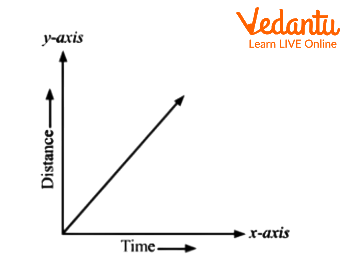
Distance - Time Graph for Uniform Motion
Here, we can see a straight line passing from the origin. Thus, for a uniform speed, the graph of distance travelled against time is a straight line. We can also determine the speed of an object from the distance-time graph . The speed of an object can be determined by calculating the slope of the distance-time graph .
We can plot the distance-time graph for accelerated motion as well. Below is the example of the distance-time graph for non-uniform motion. The nature of this graph shows non-linear variation of the distance travelled by the object with time. So, the below graph shows the motion of an object with non-uniform speed.
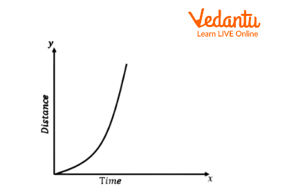
Distance - Time Graph for Non-Uniform Motion
Displacement-Time Graph
Displacement is the shortest distance between two points. Displacement-time graph gives us the information of velocity of an object. The rate at which displacement varies with time is known as velocity and the slope of the displacement-time graph gives us the velocity of an object. So, if this graph gives us a straight line which is parallel to the x-axis, then we can say that object is at rest.
Velocity-Time Graph
The rate at which velocity varies with time is called acceleration and the slope of this graph gives us the information of acceleration of an object. The variation in velocity with time for an object moving in a straight line can be described by a velocity-time graph .

Velocity - Time Graph
Here, time and velocity are represented along the x-axis and y-axis, respectively. The graph shows a straight line which is parallel to the x-axis. That means the object has uniform velocity.
Solved Examples
1. An object is moving along a circular path of radius 7 cm. What is the distance of an object when it completes half revolution.
Ans: Given, radius $r = 7\,cm$
The object is moving along a circular path. We have to calculate the distance travelled by this object when it completes half revolution.
The circumference of the circle is $2\pi r$.
So, here, its distance travelled by it would be $\pi r$.
The distance of an object would be 22 cm when it completes half revolution.
2. A car decreases its speed from $22\,\dfrac{m}{s}$ to $16\,\dfrac{m}{s}$ in 5 sec. Find the acceleration of the car.
Ans: Given, initial speed of the car is $u = 22\,\dfrac{m}{s}$
Final speed of the car $v = 16\,\dfrac{m}{s}$
Time taken $t = 5\sec $
We will use the relation $a = \dfrac{{v - u}}{t}$ to solve this
$\therefore a = \dfrac{{16 - 22}}{5} = - 1.2\,\dfrac{m}{{{s^2}}}$
So, the acceleration of the car is $a = - 1.2\,\dfrac{m}{{{s^2}}}$
Interesting Facts
Displacement can be defined from the area under the velocity-time graph.
The displacement of an object is proportional to the square of time, then we can say that the object moves with uniform acceleration .
A speedometer is a good example of instantaneous speed.
Motion can be defined with the help of graphs. We use graphs to describe the motion of an object. In a line graph, we can represent one physical quantity like distance or velocity with another quantity such as time. The different types of graphs for motion help us to understand the speed, velocity, acceleration, and also behaviour of an object.

FAQs on Graphical Representation of Motion
1. State the difference between speed and velocity.
Here are a few points which show the difference between speed and velocity.
The speed of the moving object can never be zero and thus the average speed of that object can never be zero. The average velocity of the moving object can be zero when the displacement of the object is zero.
Speed gives us an idea about how much an object has travelled in a certain period of time but in the case of velocity, it is a measure of the rapidity of the motion along with the direction of the object.
Speed is a scalar quantity. So, it gives us information about only magnitude. Velocity is a vector quantity, so we can get information about magnitude and direction.
2. Define positive acceleration and negative acceleration.
If the velocity of an object is increasing with time, then we can say that the acceleration of that object is positive. Final velocity of an object will be greater than the initial velocity of an object in case of positive acceleration. The direction of positive acceleration is the same as the direction of motion of the object.
If the velocity of an object is decreasing with time, then we can say that the acceleration of that object will be negative. The direction of negative acceleration will be opposite to the direction of motion of the object. The initial velocity will be greater than the final velocity in case of negative acceleration. Negative acceleration is also called de-acceleration or retardation.
3. State the difference between distance and displacement.
We define distance as the actual path travelled by the object but displacement is the shortest distance between the two points which an object takes. Distance travelled is not a unique path between two points but the displacement refers to a unique path between two points. The distance travelled gives the information of the type of path followed by the object. Displacement between two points gives information only about the initial and the final positions of the object. Distance never decreases with time for a moving object. It can never be zero. Displacement can decrease with time for a moving object.

- school Campus Bookshelves
- menu_book Bookshelves
- perm_media Learning Objects
- login Login
- how_to_reg Request Instructor Account
- hub Instructor Commons
- Download Page (PDF)
- Download Full Book (PDF)
- Periodic Table
- Physics Constants
- Scientific Calculator
- Reference & Cite
- Tools expand_more
- Readability
selected template will load here
This action is not available.

Lab 2: Graphical Methods of Data Analysis
- Last updated
- Save as PDF
- Page ID 22665

- Tom Weideman
- University of California, Davis
- 2.1: Background Material
- 2.2: Activities
If you're seeing this message, it means we're having trouble loading external resources on our website.
If you're behind a web filter, please make sure that the domains *.kastatic.org and *.kasandbox.org are unblocked.
To log in and use all the features of Khan Academy, please enable JavaScript in your browser.
AP®︎/College Physics 1
Course: ap®︎/college physics 1 > unit 1, representations of motion.
- Deriving displacement as a function of time, acceleration, and initial velocity
- Plotting projectile displacement, acceleration, and velocity
- Position vs. time graphs
- Why distance is area under velocity-time line
- (Choice A) CD A CD
- (Choice B) BC B BC
- (Choice C) DE C DE
- (Choice D) AB D AB
- TPC and eLearning
- What's NEW at TPC?
- Read Watch Interact
- Practice Review Test
- Teacher-Tools
- Subscription Selection
- Seat Calculator
- Ad Free Account
- Edit Profile Settings
- Classes (Version 2)
- Student Progress Edit
- Task Properties
- Export Student Progress
- Task, Activities, and Scores
- Metric Conversions Questions
- Metric System Questions
- Metric Estimation Questions
- Significant Digits Questions
- Proportional Reasoning
- Acceleration
- Distance-Displacement
- Dots and Graphs
- Graph That Motion
- Match That Graph
- Name That Motion
- Motion Diagrams
- Pos'n Time Graphs Numerical
- Pos'n Time Graphs Conceptual
- Up And Down - Questions
- Balanced vs. Unbalanced Forces
- Change of State
- Force and Motion
- Mass and Weight
- Match That Free-Body Diagram
- Net Force (and Acceleration) Ranking Tasks
- Newton's Second Law
- Normal Force Card Sort
- Recognizing Forces
- Air Resistance and Skydiving
- Solve It! with Newton's Second Law
- Which One Doesn't Belong?
- Component Addition Questions
- Head-to-Tail Vector Addition
- Projectile Mathematics
- Trajectory - Angle Launched Projectiles
- Trajectory - Horizontally Launched Projectiles
- Vector Addition
- Vector Direction
- Which One Doesn't Belong? Projectile Motion
- Forces in 2-Dimensions
- Being Impulsive About Momentum
- Explosions - Law Breakers
- Hit and Stick Collisions - Law Breakers
- Case Studies: Impulse and Force
- Impulse-Momentum Change Table
- Keeping Track of Momentum - Hit and Stick
- Keeping Track of Momentum - Hit and Bounce
- What's Up (and Down) with KE and PE?
- Energy Conservation Questions
- Energy Dissipation Questions
- Energy Ranking Tasks
- LOL Charts (a.k.a., Energy Bar Charts)
- Match That Bar Chart
- Words and Charts Questions
- Name That Energy
- Stepping Up with PE and KE Questions
- Case Studies - Circular Motion
- Circular Logic
- Forces and Free-Body Diagrams in Circular Motion
- Gravitational Field Strength
- Universal Gravitation
- Angular Position and Displacement
- Linear and Angular Velocity
- Angular Acceleration
- Rotational Inertia
- Balanced vs. Unbalanced Torques
- Getting a Handle on Torque
- Torque-ing About Rotation
- Properties of Matter
- Fluid Pressure
- Buoyant Force
- Sinking, Floating, and Hanging
- Pascal's Principle
- Flow Velocity
- Bernoulli's Principle
- Balloon Interactions
- Charge and Charging
- Charge Interactions
- Charging by Induction
- Conductors and Insulators
- Coulombs Law
- Electric Field
- Electric Field Intensity
- Polarization
- Case Studies: Electric Power
- Know Your Potential
- Light Bulb Anatomy
- I = ∆V/R Equations as a Guide to Thinking
- Parallel Circuits - ∆V = I•R Calculations
- Resistance Ranking Tasks
- Series Circuits - ∆V = I•R Calculations
- Series vs. Parallel Circuits
- Equivalent Resistance
- Period and Frequency of a Pendulum
- Pendulum Motion: Velocity and Force
- Energy of a Pendulum
- Period and Frequency of a Mass on a Spring
- Horizontal Springs: Velocity and Force
- Vertical Springs: Velocity and Force
- Energy of a Mass on a Spring
- Decibel Scale
- Frequency and Period
- Closed-End Air Columns
- Name That Harmonic: Strings
- Rocking the Boat
- Wave Basics
- Matching Pairs: Wave Characteristics
- Wave Interference
- Waves - Case Studies
- Color Addition and Subtraction
- Color Filters
- If This, Then That: Color Subtraction
- Light Intensity
- Color Pigments
- Converging Lenses
- Curved Mirror Images
- Law of Reflection
- Refraction and Lenses
- Total Internal Reflection
- Who Can See Who?
- Formulas and Atom Counting
- Atomic Models
- Bond Polarity
- Entropy Questions
- Cell Voltage Questions
- Heat of Formation Questions
- Reduction Potential Questions
- Oxidation States Questions
- Measuring the Quantity of Heat
- Hess's Law
- Oxidation-Reduction Questions
- Galvanic Cells Questions
- Thermal Stoichiometry
- Molecular Polarity
- Quantum Mechanics
- Balancing Chemical Equations
- Bronsted-Lowry Model of Acids and Bases
- Classification of Matter
- Collision Model of Reaction Rates
- Density Ranking Tasks
- Dissociation Reactions
- Complete Electron Configurations
- Elemental Measures
- Enthalpy Change Questions
- Equilibrium Concept
- Equilibrium Constant Expression
- Equilibrium Calculations - Questions
- Equilibrium ICE Table
- Intermolecular Forces Questions
- Ionic Bonding
- Lewis Electron Dot Structures
- Limiting Reactants
- Line Spectra Questions
- Mass Stoichiometry
- Measurement and Numbers
- Metals, Nonmetals, and Metalloids
- Metric Estimations
- Metric System
- Molarity Ranking Tasks
- Mole Conversions
- Name That Element
- Names to Formulas
- Names to Formulas 2
- Nuclear Decay
- Particles, Words, and Formulas
- Periodic Trends
- Precipitation Reactions and Net Ionic Equations
- Pressure Concepts
- Pressure-Temperature Gas Law
- Pressure-Volume Gas Law
- Chemical Reaction Types
- Significant Digits and Measurement
- States Of Matter Exercise
- Stoichiometry Law Breakers
- Stoichiometry - Math Relationships
- Subatomic Particles
- Spontaneity and Driving Forces
- Gibbs Free Energy
- Volume-Temperature Gas Law
- Acid-Base Properties
- Energy and Chemical Reactions
- Chemical and Physical Properties
- Valence Shell Electron Pair Repulsion Theory
- Writing Balanced Chemical Equations
- Mission CG1
- Mission CG10
- Mission CG2
- Mission CG3
- Mission CG4
- Mission CG5
- Mission CG6
- Mission CG7
- Mission CG8
- Mission CG9
- Mission EC1
- Mission EC10
- Mission EC11
- Mission EC12
- Mission EC2
- Mission EC3
- Mission EC4
- Mission EC5
- Mission EC6
- Mission EC7
- Mission EC8
- Mission EC9
- Mission RL1
- Mission RL2
- Mission RL3
- Mission RL4
- Mission RL5
- Mission RL6
- Mission KG7
- Mission RL8
- Mission KG9
- Mission RL10
- Mission RL11
- Mission RM1
- Mission RM2
- Mission RM3
- Mission RM4
- Mission RM5
- Mission RM6
- Mission RM8
- Mission RM10
- Mission LC1
- Mission RM11
- Mission LC2
- Mission LC3
- Mission LC4
- Mission LC5
- Mission LC6
- Mission LC8
- Mission SM1
- Mission SM2
- Mission SM3
- Mission SM4
- Mission SM5
- Mission SM6
- Mission SM8
- Mission SM10
- Mission KG10
- Mission SM11
- Mission KG2
- Mission KG3
- Mission KG4
- Mission KG5
- Mission KG6
- Mission KG8
- Mission KG11
- Mission F2D1
- Mission F2D2
- Mission F2D3
- Mission F2D4
- Mission F2D5
- Mission F2D6
- Mission KC1
- Mission KC2
- Mission KC3
- Mission KC4
- Mission KC5
- Mission KC6
- Mission KC7
- Mission KC8
- Mission AAA
- Mission SM9
- Mission LC7
- Mission LC9
- Mission NL1
- Mission NL2
- Mission NL3
- Mission NL4
- Mission NL5
- Mission NL6
- Mission NL7
- Mission NL8
- Mission NL9
- Mission NL10
- Mission NL11
- Mission NL12
- Mission MC1
- Mission MC10
- Mission MC2
- Mission MC3
- Mission MC4
- Mission MC5
- Mission MC6
- Mission MC7
- Mission MC8
- Mission MC9
- Mission RM7
- Mission RM9
- Mission RL7
- Mission RL9
- Mission SM7
- Mission SE1
- Mission SE10
- Mission SE11
- Mission SE12
- Mission SE2
- Mission SE3
- Mission SE4
- Mission SE5
- Mission SE6
- Mission SE7
- Mission SE8
- Mission SE9
- Mission VP1
- Mission VP10
- Mission VP2
- Mission VP3
- Mission VP4
- Mission VP5
- Mission VP6
- Mission VP7
- Mission VP8
- Mission VP9
- Mission WM1
- Mission WM2
- Mission WM3
- Mission WM4
- Mission WM5
- Mission WM6
- Mission WM7
- Mission WM8
- Mission WE1
- Mission WE10
- Mission WE2
- Mission WE3
- Mission WE4
- Mission WE5
- Mission WE6
- Mission WE7
- Mission WE8
- Mission WE9
- Vector Walk Interactive
- Name That Motion Interactive
- Kinematic Graphing 1 Concept Checker
- Kinematic Graphing 2 Concept Checker
- Graph That Motion Interactive
- Two Stage Rocket Interactive
- Rocket Sled Concept Checker
- Force Concept Checker
- Free-Body Diagrams Concept Checker
- Free-Body Diagrams The Sequel Concept Checker
- Skydiving Concept Checker
- Elevator Ride Concept Checker
- Vector Addition Concept Checker
- Vector Walk in Two Dimensions Interactive
- Name That Vector Interactive
- River Boat Simulator Concept Checker
- Projectile Simulator 2 Concept Checker
- Projectile Simulator 3 Concept Checker
- Hit the Target Interactive
- Turd the Target 1 Interactive
- Turd the Target 2 Interactive
- Balance It Interactive
- Go For The Gold Interactive
- Egg Drop Concept Checker
- Fish Catch Concept Checker
- Exploding Carts Concept Checker
- Collision Carts - Inelastic Collisions Concept Checker
- Its All Uphill Concept Checker
- Stopping Distance Concept Checker
- Chart That Motion Interactive
- Roller Coaster Model Concept Checker
- Uniform Circular Motion Concept Checker
- Horizontal Circle Simulation Concept Checker
- Vertical Circle Simulation Concept Checker
- Race Track Concept Checker
- Gravitational Fields Concept Checker
- Orbital Motion Concept Checker
- Angular Acceleration Concept Checker
- Balance Beam Concept Checker
- Torque Balancer Concept Checker
- Aluminum Can Polarization Concept Checker
- Charging Concept Checker
- Name That Charge Simulation
- Coulomb's Law Concept Checker
- Electric Field Lines Concept Checker
- Put the Charge in the Goal Concept Checker
- Circuit Builder Concept Checker (Series Circuits)
- Circuit Builder Concept Checker (Parallel Circuits)
- Circuit Builder Concept Checker (∆V-I-R)
- Circuit Builder Concept Checker (Voltage Drop)
- Equivalent Resistance Interactive
- Pendulum Motion Simulation Concept Checker
- Mass on a Spring Simulation Concept Checker
- Particle Wave Simulation Concept Checker
- Boundary Behavior Simulation Concept Checker
- Slinky Wave Simulator Concept Checker
- Simple Wave Simulator Concept Checker
- Wave Addition Simulation Concept Checker
- Standing Wave Maker Simulation Concept Checker
- Color Addition Concept Checker
- Painting With CMY Concept Checker
- Stage Lighting Concept Checker
- Filtering Away Concept Checker
- InterferencePatterns Concept Checker
- Young's Experiment Interactive
- Plane Mirror Images Interactive
- Who Can See Who Concept Checker
- Optics Bench (Mirrors) Concept Checker
- Name That Image (Mirrors) Interactive
- Refraction Concept Checker
- Total Internal Reflection Concept Checker
- Optics Bench (Lenses) Concept Checker
- Kinematics Preview
- Velocity Time Graphs Preview
- Moving Cart on an Inclined Plane Preview
- Stopping Distance Preview
- Cart, Bricks, and Bands Preview
- Fan Cart Study Preview
- Friction Preview
- Coffee Filter Lab Preview
- Friction, Speed, and Stopping Distance Preview
- Up and Down Preview
- Projectile Range Preview
- Ballistics Preview
- Juggling Preview
- Marshmallow Launcher Preview
- Air Bag Safety Preview
- Colliding Carts Preview
- Collisions Preview
- Engineering Safer Helmets Preview
- Push the Plow Preview
- Its All Uphill Preview
- Energy on an Incline Preview
- Modeling Roller Coasters Preview
- Hot Wheels Stopping Distance Preview
- Ball Bat Collision Preview
- Energy in Fields Preview
- Weightlessness Training Preview
- Roller Coaster Loops Preview
- Universal Gravitation Preview
- Keplers Laws Preview
- Kepler's Third Law Preview
- Charge Interactions Preview
- Sticky Tape Experiments Preview
- Wire Gauge Preview
- Voltage, Current, and Resistance Preview
- Light Bulb Resistance Preview
- Series and Parallel Circuits Preview
- Thermal Equilibrium Preview
- Linear Expansion Preview
- Heating Curves Preview
- Electricity and Magnetism - Part 1 Preview
- Electricity and Magnetism - Part 2 Preview
- Vibrating Mass on a Spring Preview
- Period of a Pendulum Preview
- Wave Speed Preview
- Slinky-Experiments Preview
- Standing Waves in a Rope Preview
- Sound as a Pressure Wave Preview
- DeciBel Scale Preview
- DeciBels, Phons, and Sones Preview
- Sound of Music Preview
- Shedding Light on Light Bulbs Preview
- Models of Light Preview
- Electromagnetic Radiation Preview
- Electromagnetic Spectrum Preview
- EM Wave Communication Preview
- Digitized Data Preview
- Light Intensity Preview
- Concave Mirrors Preview
- Object Image Relations Preview
- Snells Law Preview
- Reflection vs. Transmission Preview
- Magnification Lab Preview
- Reactivity Preview
- Ions and the Periodic Table Preview
- Periodic Trends Preview
- Intermolecular Forces Preview
- Melting Points and Boiling Points Preview
- Reaction Rates Preview
- Ammonia Factory Preview
- Stoichiometry Preview
- Nuclear Chemistry Preview
- Gaining Teacher Access
- Tasks and Classes
- Tasks - Classic
- Subscription
- Subscription Locator
- 1-D Kinematics
- Newton's Laws
- Vectors - Motion and Forces in Two Dimensions
- Momentum and Its Conservation
- Work and Energy
- Circular Motion and Satellite Motion
- Thermal Physics
- Static Electricity
- Electric Circuits
- Vibrations and Waves
- Sound Waves and Music
- Light and Color
- Reflection and Mirrors
- About the Physics Interactives
- Task Tracker
- Usage Policy
- Newtons Laws
- Vectors and Projectiles
- Forces in 2D
- Momentum and Collisions
- Circular and Satellite Motion
- Balance and Rotation
- Electromagnetism
- Waves and Sound
- Atomic Physics
- Forces in Two Dimensions
- Work, Energy, and Power
- Circular Motion and Gravitation
- Sound Waves
- 1-Dimensional Kinematics
- Circular, Satellite, and Rotational Motion
- Einstein's Theory of Special Relativity
- Waves, Sound and Light
- QuickTime Movies
- About the Concept Builders
- Pricing For Schools
- Directions for Version 2
- Measurement and Units
- Relationships and Graphs
- Rotation and Balance
- Vibrational Motion
- Reflection and Refraction
- Teacher Accounts
- Task Tracker Directions
- Kinematic Concepts
- Kinematic Graphing
- Wave Motion
- Sound and Music
- About CalcPad
- 1D Kinematics
- Vectors and Forces in 2D
- Simple Harmonic Motion
- Rotational Kinematics
- Rotation and Torque
- Rotational Dynamics
- Electric Fields, Potential, and Capacitance
- Transient RC Circuits
- Light Waves
- Units and Measurement
- Stoichiometry
- Molarity and Solutions
- Thermal Chemistry
- Acids and Bases
- Kinetics and Equilibrium
- Solution Equilibria
- Oxidation-Reduction
- Nuclear Chemistry
- Newton's Laws of Motion
- Work and Energy Packet
- Static Electricity Review
- NGSS Alignments
- 1D-Kinematics
- Projectiles
- Circular Motion
- Magnetism and Electromagnetism
- Graphing Practice
- About the ACT
- ACT Preparation
- For Teachers
- Other Resources
- Solutions Guide
- Solutions Guide Digital Download
- Motion in One Dimension
- Work, Energy and Power
- TaskTracker
- Other Tools
- Algebra Based Physics
- Frequently Asked Questions
- Purchasing the Download
- Purchasing the CD
- Purchasing the Digital Download
- About the NGSS Corner
- NGSS Search
- Force and Motion DCIs - High School
- Energy DCIs - High School
- Wave Applications DCIs - High School
- Force and Motion PEs - High School
- Energy PEs - High School
- Wave Applications PEs - High School
- Crosscutting Concepts
- The Practices
- Physics Topics
- NGSS Corner: Activity List
- NGSS Corner: Infographics
- About the Toolkits
- Position-Velocity-Acceleration
- Position-Time Graphs
- Velocity-Time Graphs
- Newton's First Law
- Newton's Second Law
- Newton's Third Law
- Terminal Velocity
- Projectile Motion
- Forces in 2 Dimensions
- Impulse and Momentum Change
- Momentum Conservation
- Work-Energy Fundamentals
- Work-Energy Relationship
- Roller Coaster Physics
- Satellite Motion
- Electric Fields
- Circuit Concepts
- Series Circuits
- Parallel Circuits
- Describing-Waves
- Wave Behavior Toolkit
- Standing Wave Patterns
- Resonating Air Columns
- Wave Model of Light
- Plane Mirrors
- Curved Mirrors
- Teacher Guide
- Using Lab Notebooks
- Current Electricity
- Light Waves and Color
- Reflection and Ray Model of Light
- Refraction and Ray Model of Light
- Classes (Legacy Version)
- Teacher Resources
- Subscriptions

- Newton's Laws
- Einstein's Theory of Special Relativity
- About Concept Checkers
- School Pricing
- Newton's Laws of Motion
- Newton's First Law
- Newton's Third Law
Graphical Method of Vector Addition Video Tutorial
The Graphical Method of Vector Addition Video Tutorial explains and demonstrates the method of adding two or more vectors using a scaled vector diagrams. The video includes a step-by-step procedure, two examples, and a discussion of the various pitfalls one might experience when adding vectors using the graphical method. The video lesson answers the following question:
- How can a scaled diagram be used to graphically add two or more vectors?
View Video Tutorial
Help us help you.

Got any suggestions?
We want to hear from you! Send us a message and help improve Slidesgo
Top searches
Trending searches

11 templates

teacher appreciation

mother teresa
18 templates

memorial day
12 templates

summer vacation
25 templates

Physics Presentation templates
To understand how the world we know works like it does, one of the main scientific disciplines in charge of providing answers is physics. get these google slides themes and powerpoint templates and prove that the formula "slidesgo + creativity = success" is true, related collections.

3 templates

Middle School
15 templates

High School
22 templates

5 templates

Science Subject for Middle School - 6th Grade: Physics I
If you understand physics, you understand how the world works! Prepare a fun lesson where your students will understand the basics of physics: from Newton’s laws to fluid dynamics, accelerations, movement, and reactions... all in a visual and fun way. Editing these slides will turn to a fun experiment if...

Energy and Waves - Physics - 11th Grade
Download the "Energy and Waves - Physics - 11th Grade" presentation for PowerPoint or Google Slides. High school students are approaching adulthood, and therefore, this template’s design reflects the mature nature of their education. Customize the well-defined sections, integrate multimedia and interactive elements and allow space for research or group...

Premium template
Unlock this template and gain unlimited access
Science Subject for Elementary - 2nd Grade: Physics
So if you drop a bowling ball and a feather from a skyscraper, they hit the ground at the same time? That can’t be true, right? Explain your little students how physics work with this beautiful template for Google Slides and PowerPoint, the design is completely editable and includes resources...

Static Electricity Lesson for Elementary
Who hasn't tried to rub a balloon on their head and see how the hair stands up as they pull the balloon away? That's due to static electricity, and since this example is very popular among kids, you'll find success in your lesson if you use our template! The electrons...

Physics Subject for Middle School: Material Properties
Download the Physics Subject for Middle School: Material Properties presentation for PowerPoint or Google Slides. If you’re looking for a way to motivate and engage students who are undergoing significant physical, social, and emotional development, then you can’t go wrong with an educational template designed for Middle School by Slidesgo!...

Analyzing Albert Einstein's Theory of Relativity Thesis Defense
Download the Analyzing Albert Einstein's Theory of Relativity Thesis Defense presentation for PowerPoint or Google Slides. Congratulations, you have finally finished your research and made it to the end of your thesis! But now comes the big moment: the thesis defense. You want to make sure you showcase your research...

Science Subject for Elementary - 2nd Grade: Science Fair
It's scientifically proven that science classes are among the most popular in schools. Some even hold science fairs, giving kids the chance to show & tell their own experiments and inventions. If you need to create a presentation about this, put your brain to work because this template is made...

History of The Atom
Download the "History of The Atom" presentation for PowerPoint or Google Slides. The education sector constantly demands dynamic and effective ways to present information. This template is created with that very purpose in mind. Offering the best resources, it allows educators or students to efficiently manage their presentations and engage...

Physical Science - Physics - 7th Grade
Ignite the scientific curiosity in your 7th grade students with this comprehensive Google Slides and PowerPoint template. Styled in a cheerful yellow, this fun and illustrated template is guaranteed to guide your students through the fascinating world of physics. Get ready to unveil the laws of physics, with the plethora...

Pendulum Experiment: Introduction to Physics
Download the Pendulum Experiment: Introduction to Physics presentation for PowerPoint or Google Slides. The education sector constantly demands dynamic and effective ways to present information. This template is created with that very purpose in mind. Offering the best resources, it allows educators or students to efficiently manage their presentations and...

Force, Motion, and Energy - Science - 11th Grade
For as long as we are people, we live in a physical world. Things move, slide, collide, get warmer or colder, accelerate... From the laws of motion to the concept of potential and kinetic energy, our comprehensive template allows you to explore these concepts in an engaging and interactive way....

Operations and Algebraic Thinking - Math for Elementary
If you're a teacher, you might have heard that math is a polarizing subject—some students love it and others not so much. Well, let's help grow the number of students that love it with this new template. Designed for educational purposes, you can turn this design into a slideshow for...

Waves and Optics - Science - 10th Grade
Download the "Waves and Optics - Science - 10th Grade" presentation for PowerPoint or Google Slides. High school students are approaching adulthood, and therefore, this template’s design reflects the mature nature of their education. Customize the well-defined sections, integrate multimedia and interactive elements and allow space for research or group...

Displacement in Physics
Download the Displacement in Physics presentation for PowerPoint or Google Slides. The education sector constantly demands dynamic and effective ways to present information. This template is created with that very purpose in mind. Offering the best resources, it allows educators or students to efficiently manage their presentations and engage audiences....

Electrical Energy and Power in Physics
Download the Electrical Energy and Power in Physics presentation for PowerPoint or Google Slides. High school students are approaching adulthood, and therefore, this template’s design reflects the mature nature of their education. Customize the well-defined sections, integrate multimedia and interactive elements and allow space for research or group projects—the possibilities...

Science Subject for Middle School - 6th Grade: Physics II
Physics explain a lot of things that happen in our world. Why water flows and moves like that? Why objects interact with fluids the way they do? This funny template will make your classes more entertaining and perhaps more interesting for your students. The various illustrations included complement any explanation,...

Physics for Middle School Infographics
Download the "Physics for Middle School Infographics" template for PowerPoint or Google Slides and discover the power of infographics. An infographic resource gives you the ability to showcase your content in a more visual way, which will make it easier for your audience to understand your topic. Slidesgo infographics like...

Force, Motion, and Energy - Science - 11th Grade Infographics
Download the "Force, Motion, and Energy - Science - 11th Grade Infographics" template for PowerPoint or Google Slides and discover the power of infographics. An infographic resource gives you the ability to showcase your content in a more visual way, which will make it easier for your audience to understand...
- Page 1 of 5
Great presentations, faster
Slidesgo for Google Slides :
The easy way to wow

COMMENTS
Department of Physics & Astronomy Lab Manual Undergraduate Labs Graphical Presentation of Data Guidelines for Making Graphs Titles should tell the reader exactly what is graphed Remove stray lines, legends, points, and any other unintended additions by the computer that does not add to your graph.
Graphical analysis of motion can be used to describe both specific and general characteristics of kinematics. Graphs can also be used for other topics in physics. An important aspect of exploring physical relationships is to graph them and look for underlying relationships.
Example 3.4.6 3.4. 6: Calculating Acceleration from a Graph of Velocity versus Time. Now consider the motion of the jet car as it goes from 165 m/s to its top velocity of 250 m/s, graphed in Figure 3.4.6 3.4. 6. Time starts at zero, and the initial position and velocity are 2900 m and 165 m/s, respectively.
Vector Addition: Head-to-Tail Method. The head-to-tail method is a graphical way to add vectors, described in Figure below and in the steps following. The tail of the vector is the starting point of the vector, and the head (or tip) of a vector is the final, pointed end of the arrow.. Figure. (a) Draw a vector representing the displacement to the east. (b) Draw a vector representing the ...
This page titled 2.8: Graphical Analysis of One-Dimensional Motion is shared under a license and was authored, remixed, and/or curated by via that was edited to the style and standards of the LibreTexts platform; a detailed edit history is available upon request. Graphs of motion can be used to analyze motion.
The head-to-tail method is a graphical way to add vectors. The tail of the vector is the starting point of the vector, and the head (or tip) of a vector is the pointed end of the arrow. The following steps describe how to use the head-to-tail method for graphical vector addition. Let the x-axis represent the east-west direction.
In physics, graphs are often used to provide a visual presentation of data, which may be much more meaningful than just presenting numbers in a table. When data are presented in graphical form, the shape of the graph can vary considerably. Figure 1 shows some of the different shapes that you may encounter in any of the physical sciences.
is that many students are unable to perform tasks involving the presentation of one-dimensional motion in a graphical form, or to analyze a set of data for orbital motion in order to extract physically significant information from it" (p. 3). 2 Student Performance Q&A: 2005 AP Physics B Free-Response Questions.
The Graphical Method of Vector Addition Video Tutorial explains and demonstrates the method of adding two or more vectors using a scaled vector diagrams. The video includes a step-by-step procedure, two examples, and a discussion of the various pitfalls one might experience when adding vectors using the graphical method. The video lesson ...
For calculating acceleration draw a perpendicular on the x-axis from the graph point as shown in the figure. Here the acceleration will be equal to the slope of the velocity-time graph. Distance travelled will be equal to the area of the triangle, Therefore, Distance traveled= (Base × Height)/2. Just like in the distance-time graph, when the ...
If the graph is linear (i.e., a line with a constant slope), it is easy to find the slope at any point and you have the slope for every point. Graphical analysis of motion can be used to describe both specific and general characteristics of kinematics. Graphs can also be used for other topics in physics.
Assignment guidance Graphical presentation. Assignment guidance. The Higher Physics Assignment is made up of Research and Report. You must either carry out two experiments, or carry out an ...
Picturing Motion. Straight-line motion follows a path directly between two points without turning left or right. Ex. Forward and backward, up and down, or north and south. A description of motion relates to place and time. You must be able to answer the questions of where and when an object is positioned to describe its motion.
Step 2: Determine how much time you have for your presentation: this will control how much time you have to talk about each part of your outline (see below) Step 3: Identify the main points you want to convey: you can reasonably convey only 2-3 main points in a 20- or 30-minute talk. Step 4: Create an outline of your talk: this will build in ...
Origin is on all Physics 403 computers. What it can do: 1. Graphical presentation of data 2. Data analysis 3. Preparation of publication-quality figures • Specially designed for scientific graphics • "Standard"Windows application, does not require knowledge of C++ or any other high level computer language
03 September 2019. The language of science is an integration of different representation instruments, including words, pictures, equations, and graphs. Graphs have a fundamental role in physics and in physics education. A wide literature in physics education evidenced the difficulties of students in reading, constructing, and interpreting graphs.
It can also be found out by taking the ratio of change in the y-coordinates to change in the x-coordinates. Graphical representation of motion generally uses graphs and with the help of graphs, we can represent the motion of an object. In the graphical representation of motion, we should take the dependent quantity along the y-axis and the ...
Campus Bookshelves. University of California Davis. UCD: Physics 9A Lab. Lab 2: Graphical Methods of Data Analysis. Expand/collapse global location.
Choose 1 answer: Learn for free about math, art, computer programming, economics, physics, chemistry, biology, medicine, finance, history, and more. Khan Academy is a nonprofit with the mission of providing a free, world-class education for anyone, anywhere.
Graphical Method of Vector Addition Video Tutorial. The Graphical Method of Vector Addition Video Tutorial explains and demonstrates the method of adding two or more vectors using a scaled vector diagrams. The video includes a step-by-step procedure, two examples, and a discussion of the various pitfalls one might experience when adding vectors ...
Solved Problems Based on Graphical Representation of Equation of Motion. Q.1. A car is moving on a straight road at a uniform acceleration. The velocity of the car at different times is given below. Draw its speed-time graph and calculate its acceleration and also find out the distance covered by it in 30 seconds.
Download the "Energy and Waves - Physics - 11th Grade" presentation for PowerPoint or Google Slides. High school students are approaching adulthood, and therefore, this template's design reflects the mature nature of their education. Customize the well-defined sections, integrate multimedia and interactive elements and allow space for ...
Welcome to the General Physics 1 12 Alternative Delivery Mode (ADM) Module on Graphical Presentation! This module was collaboratively designed, developed and reviewed by educators both from public and private institutions to assist you, the teacher or facilitator in helping the learners meet the standards set by the K to 12 Curriculum while ...