Research on the application of robot welding technology in modern architecture
- Original article
- Published: 13 November 2021
- Volume 14 , pages 681–690, ( 2023 )

Cite this article

- Tao Guan ORCID: orcid.org/0000-0001-9124-8818 1
449 Accesses
3 Citations
Explore all metrics
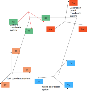
In order to explore the application of robot welding machine technology in modern buildings, this paper analyzes the robot welding technology, combines machine vision to analyze the visual calibration of the welding robot, and corrects the calibration results through experimental data to obtain the robot hand-eye parameters. Moreover, this paper uses Rodriguez transformation to convert the rotation vector into a rotation matrix and combines with the translation vector to obtain the conversion matrix from the camera coordinate system to the calibration board coordinate system. In addition, this paper combines the simulation test to evaluate the technical application effect of robot welding technology. From the simulation results, it can be seen that robot welding technology can meet the welding needs of modern buildings. Finally, this paper analyzes the application of robotic welding technology in modern buildings. The research results show that robot welding technology can play an important role in modern buildings.
This is a preview of subscription content, log in via an institution to check access.
Access this article
Price includes VAT (Russian Federation)
Instant access to the full article PDF.
Rent this article via DeepDyve
Institutional subscriptions
Innovations in Infrastructure Service Robots

On-Site Automatic Construction of Partition Walls with Mobile Robot and Computer Vision

Status Quo of Construction Robotics: Potentials, Applications and Challenges
Chai X, Zhang N, He L et al (2020) Kinematic sensitivity analysis and dimensional synthesis of a redundantly actuated parallel robot for friction stir welding[J]. Chinese J Mech Eng 33(1):1–10
Article Google Scholar
Chen S, Zhou Y, Xue J et al (2017) High rotation speed friction stir welding for 2014 aluminum alloy thin sheets[J]. J Mater Eng Perform 26(3):1337–1345
Du JH, Deng JX, Huang KJ et al (2018) Seam tracking system based on rotating arc sensor for robot arc welding[J]. J Discrete Math Sci Cryptography 21(6):1407–1412
Fang HC, Ong SK, Nee AYC (2017) Adaptive pass planning and optimization for robotic welding of complex joints[J]. Advances in Manufacturing 5(2):93–104
Feucht T, Lange J, Erven M et al (2020) Additive manufacturing by means of parametric robot programming [J]. Construction Robotics 4(1):31–48
Haitao L, Tingke W, Jia F et al (2021) Analysis of typical working conditions and experimental research of friction stir welding robot for aerospace applications[J]. Proc Inst Mech Eng C J Mech Eng Sci 235(6):1045–1056
Han L, Zhong Q, Chen G et al (2019) Development of local dry underwater welding technology[J]. J ZheJiang Univ (engineering Science) 53(7):1252–1264
Google Scholar
Hou Z, Xu Y, Xiao R et al (2020) A teaching-free welding method based on laser visual sensing system in robotic GMAW[J]. Int J Adv Manufacturing Technol 109(5):1755–1774
Jichang G, Zhiming Z, Xin W et al (2018) Numerical solution of the inverse kinematics and trajectory planning for an all-position welding robot[J]. J Tsinghua Univ (sci Technol) 58(3):292–297
Kim J, Lee J, Chung M et al (2021) Multiple weld seam extraction from RGB-depth images for automatic robotic welding via point cloud registration[J]. Multimed Tools Appl 80(6):9703–9719
Liu Y, Ren L, Tian X (2019) A robot welding approach for the sphere-pipe joints with swing and multi-layer planning[J]. Int J Adv Manufacturing Technol 105(1):265–278
Łukasik Z, Kuśmińska-Fijałkowska A, Kozyra J et al (2018) The problem of power supply for station with industrial robot in an automated welding process[J]. Electr Eng 100(3):1365–1377
Michal D, Košťál P, Lecký Š et al (2018) Racionalization of Robotic Workstation in Welding Industry[J]. Vedecké Práce Materiálovotechnologickej Fakulty Slovenskej Technickej Univerzity v Bratislave so Sídlom v Trnave 26(42):159–164
Ströber K, Abele C (2018) Titanium Welding Technology for Series Production[J]. Lightweight Des Worldw 11(4):12–15
Tam W, Cheng L, Wang T et al (2019) An improved genetic algorithm based robot path planning method without collision in confined workspace[J]. Int J Model Ident Control 33(2):120–129
Wang Y, Chen X, Konovalov SV (2017) Additive manufacturing based on welding arc: a low-cost method[J]. J Surf Invest 11(6):1317–1328
Wang Q, Jiao W, Wang P et al (2020) Digital twin for human-robot interactive welding and welder behavior analysis[J]. IEEE/CAA J Autom Sinica 8(2):334–343
Yang L, Li E, Long T et al (2018a) A welding quality detection method for arc welding robot based on 3D reconstruction with SFS algorithm[J]. Int J Adv Manufacturing Technol 94(1):1209–1220
Yang L, Li E, Long T et al (2018b) A novel 3-D path extraction method for arc welding robot based on stereo structured light sensor[J]. IEEE Sens J 19(2):763–773
Yang L, Li E, Long T et al (2018c) A high-speed seam extraction method based on the novel structured-light sensor for arc welding robot: a review[J]. IEEE Sens J 18(21):8631–8641
Zhang B, Shi Y, Gu S (2019) Narrow-seam identification and deviation detection in keyhole deep-penetration TIG welding[J]. Int J Adv Manufacturing Technol 101(5):2051–2064
Zou Y, Lan R (2019) An end-to-end calibration method for welding robot laser vision systems with deep reinforcement learning[J]. IEEE Trans Instrum Meas 69(7):4270–4280
Download references
There was no outside funding or grants received that assisted in this study.
Author information
Authors and affiliations.
Architectural Engineering Institute, Xinyang Vocational and Technical College, Xinyang, 464000, China
You can also search for this author in PubMed Google Scholar
Corresponding author
Correspondence to Tao Guan .
Ethics declarations
Conflict of interest.
The author declared that they have no conflicts of interest to this work. I declare that I do not have any commercial or associative interest that represents a conflict of interest in connection with the work submitted.
Additional information
Publisher's note.
Springer Nature remains neutral with regard to jurisdictional claims in published maps and institutional affiliations.
Rights and permissions
Reprints and permissions
About this article
Guan, T. Research on the application of robot welding technology in modern architecture. Int J Syst Assur Eng Manag 14 , 681–690 (2023). https://doi.org/10.1007/s13198-021-01473-5
Download citation
Received : 24 August 2021
Revised : 01 October 2021
Accepted : 22 October 2021
Published : 13 November 2021
Issue Date : April 2023
DOI : https://doi.org/10.1007/s13198-021-01473-5
Share this article
Anyone you share the following link with will be able to read this content:
Sorry, a shareable link is not currently available for this article.
Provided by the Springer Nature SharedIt content-sharing initiative
- Welding technology
- Modern technology
- Application analysis
- Find a journal
- Publish with us
- Track your research
Thank you for visiting nature.com. You are using a browser version with limited support for CSS. To obtain the best experience, we recommend you use a more up to date browser (or turn off compatibility mode in Internet Explorer). In the meantime, to ensure continued support, we are displaying the site without styles and JavaScript.
- View all journals
- My Account Login
- Explore content
- About the journal
- Publish with us
- Sign up for alerts
- Open access
- Published: 31 December 2022
Design and analysis of welding inspection robot
- Pengyu Zhang 1 ,
- Ji Wang 1 ,
- Feng Zhang 1 ,
- Peiquan Xu 1 ,
- Leijun Li 2 &
- Baoming Li 3
Scientific Reports volume 12 , Article number: 22651 ( 2022 ) Cite this article
2384 Accesses
4 Citations
Metrics details
- Electrical and electronic engineering
- Mechanical engineering
Periodic inspection, commonly performed by a technician, of weld seam quality is important for assessing equipment reliability. To save labor costs and improve efficiency, an autonomous navigation and inspection robot is developed. The development process involves the design of chassis damping, target detection mechanism, control system, and algorithms. For performing weld inspection in complex, outdoor, environments, an algorithm is developed for the robot to avoid any obstacles. This algorithm for planning the inspection route is based on an improved timed-elastic-band (TEB) algorithm. The developed robot is capable of conducting inspection tasks in complex and dangerous environments efficiently and autonomously.
Path planning and smoothing of mobile robot based on improved artificial fish swarm algorithm

An intelligent fuzzy-particle swarm optimization supervisory-based control of robot manipulator for industrial welding applications

Motion control and positioning system of multi-sensor tunnel defect inspection robot: from methodology to application
Introduction.
With the rapid developments, robots can perform simple or complex tasks in dangerous environments that are beyond people's reach. Today, the use of robots as work aids has become increasingly common in both industrial and consumer spaces. Robots can reduce labor costs, save time, improve safety, and improve the quality of work 1 . Robots also play a significant role in welding, such as spot welding for automotives, arc welding for bridge girders, and welding of polymer-matrix composites. Welding is widely used for metallic materials, from vessels and pipelines to bridges and railways 2 . Good weld quality can ensure the strength and toughness of the joints. During service, welds often will deteriorate, by corrosion and fatigue cracking, and result in structural failures. The most serious failures often involve welds in critical locations, where damage caused by corrosion leads to cracking, leakage, or bursting of vessels. In large-scale infrastructures where the welds deteriorate over a large area, it is impractical and cumbersome to inspect the welds using human labor. The use of robots becomes necessary and feasible for these cases 3 . The design of weld inspection robots revolves around two questions: how can the robot accurately reach the place where the weld is located, and how can the robot accurately inspect the weld.
Different solutions have been proposed by researchers to solve these essential weld-inspection robotic questions. A robotic climber with multiple breathing chambers for inspection was designed for the inspection of concrete walls 4 . The propulsion system consisted of three omnidirectional drive wheels with a great maneuverability. Combined with a vacuum system comprising seven controllable vacuum chambers and a large fluid reservoir operating system, the robot had pressure sensors and valves integrated for controls. Shang et al. introduced a method that utilized neodymium permanent magnets for bonding, giving the robot a payload-carrying capacity 5 . The arrangement of the magnets improved the ground clearance, enabling the robot to overcome obstacles. To be able to work on curved surfaces, a wheeled robot with two articulated segments was designed, which had the advantages of high speed and good maneuverability.
A robot with magnetic wheels and vision sensors for defect detection was designed, and the drive mechanisms of inspection robots had included three forms: a track, a wheel, and a leg 6 , 7 . Adsorption or magnet suction affixed to the location of detection had been the most common for welding inspecting robots. The sensors would detect the weld seam and then extracts the weld seam geometry, and correct the robot's position in real time 8 , 9 , but the degree of automation was low and the requirements for sensor accuracy were high.
Inspection robots have recently evolved to become autonomous and semi-autonomous, for saving inspection time and reducing labor costs. Nita and other researchers 10 have studied a semi-autonomous tracked inspection robot to detect defects in building ceilings. The developed inspection robots were equipped with wireless cameras and data processing functions, which could provide valuable information for the repair of the damaged structures. The inspection robot was able to assess the damage without the need for an engineer on site. Krenich 11 designed a six-axis robot that could move autonomously for inspection, while a human could also inspect around the weld seam with a camera carried by the robot. Bruzzone 12 introduced a mobile robot with a hybrid wheel and leg design, which featured wheels that could roll on flat grounds at a high speed, while the legs enabled the robot to avoid obstacles and to climb hills 13 .
Detection algorithms were developed for corrosion and cracking in aged welds. The use of advanced vision algorithms based on deep learning and machine learning made it possible to detect and recognize the defects. An algorithm based on an improved Gaussian mixture model for weld seam detection and classification was introduced by Sun et al. 14 It could classify the identify the weld defects with a high accuracy and in real-time. Li et al. proposed a deep learning-based algorithm for weld seam image recognition 15 , which accelerated the neural training on several thousand images of the welds. The disadvantage of this algorithm was that it was too computationally intensive and hardware demanding. Yang et al. proposed a method to improve the defect localization of U-net mesh to improve the automatic localization accuracy for weld detection 16 . For low-cost robot development using low- to mid-cost main control boards, less computationally intensive algorithms need to be developed to achieve the identification and localization of weld defects.
Based on the above survey of literature, the objectives of the present research include: (1) Design of an autonomous weld inspection robot and its control system. The robot can achieve autonomous weld inspection, and can pass smoothly between narrow spaces with less time while autonomously avoiding obstacles. (2) Design of a yolo5-based target algorithm for weld seam detection and identification in complex environments.
Figure 1 shows an overview of the scope-of-work for the autonomous weld inspection robot, which dodges obstacles in a complex environment and performs inspection of the weld seam at the inspection point.

Work overview of weld inspection robot.
Design layout
The design of the autonomous inspection robot is divided into four different components: mechanical structure design, chassis motion control design, vision detection system design, and control system architecture design.
Structural design of the robot
An aluminum chassis is used as the main frame of the robot, and each motor is individually attached to the chassis through a motor mounting plate. Shock absorbers are placed between the motor mounting plate and the chassis to reduce the vibration of the robot and to help it pass through obstacles as shown in Fig. 2 a, so that the robot maintains its posture when the wheels cross over the obstacles. Each wheel is controlled by a separate gear motor for proper power distribution as well as flexible control. Encoders and a 1:90 gear ratio allow large torques to be transmitted to the wheels. High precision motors provide precise feedback of speed and position information. The four-wheel drive allows for fast turning and easier passage through complex roads. Due to the high mounting position of the radar, smaller obstacles cannot be detected, so ultrasonic sensors and infrared sensors are used to solve the collision problems caused by the blind spots of the radar. The main control system is mounted on the chassis and equipped with a sensor-radar with obstacle detection functions. For weld seam detection, the robot's detection system consists of a camera, two servos, two brackets and several bolts. Adjusting the orientation of the servos allows for multi-directional detection as shown in Fig. 2 b–d. The information received by the inspection system is transmitted to a PC, on which the inspection information can be viewed and analyzed remotely. The complete structural design of the robot is shown in Fig. 3 .

Status of the shock absorber and visual head.

Structural design of the robot.
Chassis motion control design
Popular control models for chassis drive include the Wheel Differential model, Ackerman model, and Omnidirectional model. The turning radius of the Ackerman model cannot be 0, which does not allow the robot to turn in narrow space. The Omnidirectional model needs to use McNamee wheels instead of the common wheels. In addition, the gaps between each small wheel of the McNamee wheel are liable to be struck by foreign objects and affect the robot's movement. Therefore, the Wheel Differential model is selected, and optimized for turning around tight corners and for reducing sliding friction.
For the kinematics of the robot, a local coordinate frame, denoted as ( x , y , z ), is located at the center of gravity ( COG ) of the model. The motion of the robot is on the horizontal plane, formed by the Xw and Yw axes of the world coordinate system, shown in Fig. 4 a.

( a ) Motion model of the differential speed robot. ( b ) The steering model.
The instantaneous center of rotation of the robot is ICR , the linear velocity of the left wheel is V L , the linear velocity of the right wheel is V R , the angular velocity is ω , the distance between the two wheels is L , and the distance from the left wheel to the center of the circle is r c .
The physical relationship between angular velocity, linear velocity (v), and radius of motion of the differential robot is as follows:
The decomposition of the velocity of the left wheel and the right wheel can be found as:
From this, the relationship between the overall linear velocity of the robot, the angular velocity, and the left and right wheels can be solved as follows:
As shown in Fig. 4 b, the left and right wheels of the robot designed are configured in parallel, and the robot turning is realized by the speed difference between the left wheel and the right wheel. The radius of curvature of the turn increases when the speed difference between the left and right wheels is larger. When the robot works in a narrow space, the robot turns around its middle vertical axis, i.e., the left and right wheels have the same speed but in opposite directions, and the turning radius is 0.
The performance of key parts of the robot needs to be analyzed using specialized software before it is actually applied in order to avoid unnecessary waste of time and money 17 . In order to investigate the slippage problem of the above motion model, the simulation is carried out in gazebo. The dynamic tag is added to the tire link tag and the ground link tag in the XACRO file of the robot model. A dynamic tag is to add to measure the friction coefficient between the tire and the ground. The parameters are shown in Table 1 . Figure 5 a shows the rotation speed of the inspection robot around its own central axis. Figure 5 b shows the speed test of the inspection robot walking a straight line. Through the simulation, it is found that the motion model can complete going straight and rotating, while the occurrence of slippage is relatively mild.

Testing the chassis in a simulation environment: ( a ) Turning test. ( b ) Straight-line speed test.
Vision inspection system
The visual inspection function is for identifying and locating the weld seam. The images are captured at the robot side and the weld seam pictures are identified at the computer side using YOLOv5 inspection algorithm. The YOLOv5 based target detection algorithm, which has the advantages of high detection speed and lightweight deployment model, is used for the robot's inspection system. The YOLOv5 algorithm has four structures (i.e., s, m, l, and x) to represent different depths and widths of the network. It uses indicators to deepen and widen the network, but as the detection accuracy increases, the response velocity becomes progressively slower. The device design in this study requires model lightweight, real-time responses, and any-size image input, so YOLOv5 is chosen as the benchmark model, and its structure is shown in Fig. 6 .

YOLOv5 network structure.
A brief description of Yolov5s model
The YOLOv5 network structure is consisted of the input, backbone, neck, and detection end. The input includes the data enhancement of the mosaic, adaptive calculations of the anchor frame and adaptive scaling of the image. The back-bone is mainly composed of the CBS (convolution, BN layer, SiLU activation function), SPPF (spatial pyramid pooling-fast), and C3 (concentrated-comprehensive convolution) modules 18 . Among them, the batch normalization (BN) layer solves the problems of gradient disappearance and gradient explosion through data normalization. The sigmoid weighted linear unit (SiLU) activation function is a smooth and non-monotonic function, and it prevents the gradient from gradually decreasing to 0 during slow training.
The neck is the combination of FPN 19 and PANet 20 . The deep-feature map contains stronger semantic features and weaker localization information, while the shallow-feature map contains stronger location information and weaker semantic features. FPN transfers the semantic features from the deep-layer to the shallow-layer to enhance the semantic representation at multiple scales, while PANet transfers the location information from the shallow-layer to the deep-layer to enhance localization at multiple scales. PANet adds a bottom-up direction enhancement on top of FPN.
For network training, the loss function plays an important role in the weld detection model, which marks the difference between the predicted and actual values of the model. In YOLOv5s, a joint loss function is used to train bounding box regression, classification, and confidence. The used loss function ( L l oss ) is as follows 21 :
where L cls indicates the classification error; L box indicates the bounding box regression error; L conf indicates the confidence error.
Acquisition and annotation of images
The weld seam is inspected and the acquisition photos are of the completed weld seam. The image acquisition device is a camera (China Vistra Q16 2k usb camera) with an f-value of 1.8. Photographs of the weld seam are collected in different environments (partially obscured weld seam, weld seam at various distances from the camera). A total of 300 images of the weld seam are collected at a distance of about 20–30 cm. To speed up the model training, the images are compressed to 512 × 341 pixels, and saved in jpg format. Example images are shown in Table 2 . The collected images are annotated using LabeIImg, and the annotation produces xml files for model training. The data are divided into training set, validation set, and test set, with a ratio of 7:2:1, while there are no data duplications among the sets.
Experimental environment and parameter setting
The training model for weld detection is simulated on an HP Shadow Wizard computer with the configurations shown in Table 3 .
The hyperparameters optimized for training using the above hardware are: epoch value is 150, learning rate is 0.01, momentum is 0.937, weight decay is 0.0005, batch size is 16, workers are 8, optimizer is stochastic gradient descent (SGD), and a single graphic processing unit (GPU) is used to speed up the training. All hyperparameters are performed for the pre-training on the Validation set. The change in the loss values of the pre-training process is shown in Fig. 7 . It can be seen that the loss value decreases rapidly at the beginning of the training period, and after 50 rounds of training, it tends to be smooth and converges, without any underfitting or overfitting.

Convergence results of the pre-training model.
Control architecture
Electronics and control.
The control architecture of the robot is shown in Fig. 8 . The motion module is controlled by four DC motors with an encoder (gear ratio 1:90, size 25 × 25 × 80 mm), two motors are installed on each side of the chassis, and all motors are connected to the L298n motor driver board through a Dupont cable. The motor driver board and the Raspberry Pi main control board are connected through the IO port. The Raspberry Pi subscribes to the data from the encoder through the IO port, and it processes the data and sends speed commands to the motors. The sensing module of the robot consists of the LIDAR (Lidar A1M8), a camera head, an odometer, and an infrared sensor. The laser sensor, communicating with the Raspberry Pi through a USB port, is used for building a map of the surrounding environment, positioning, and avoiding obstacles. However, LIDAR has a blind scanning area, and there is a possibility that obstacles in the complex environment are not perceived, so the infrared sensor is used to supplement and improve the obstacle sensing. The odometer is used for robot positioning, and the LIDAR positioning is used to improve the odometer accuracy. The camera head is connected to the Raspberry Pi via a USB port for weld detection. The power supply module consists of two batteries (12 V 5000 mAh; 12 V 3000 mAh). The 5000 mAh battery supplies power to the motor driver board L298n. The 3000 mAh battery supplies power to the Raspberry Pi mainboard, and the rest of the sensors are powered through a USB or IO port.

Control system of the robot.
The motors do not use stm32 or the Arduino control method, but directly connect to the motor driver board through the IO port on the Raspberry Pi, which improves the convenience of operation and the sensitivity of control. The core controller of the robot is the Raspberry Pi 4B. The data processed on this robot is moderate, so the Raspberry Pi 4B is sufficient, which has Ubuntu 18.04 Linux and Robot Operating System (ROS) installed. The data collected by various sensors are transferred to the ROS system for processing. The various sensors, main control board, GUI, and PC are integrated through the ROS framework. To reduce the pressure on the Raspberry Pi for processing the data, the collected data are transferred through WIFI from Raspberry Pi to the PC, for processing on the distributed framework of ROS.
Graphical user interface (GUI)
When they are connected to the same network, both the robot and PC can be remotely monitored and controlled through the distributed ROS. Communication between the robot and control device is carried out through ROS' Message Queue Telemetry Transfer (MQTT). When the navigation control node is started on the mobile side, a message is received on the PC, and a map building command can be executed on the PC at the same time, which controls the robot to build a map and issues a point-to-point cruise operation. This operation reduces the computational pressure on the Raspberry Pi 4B onboard the robot. A graphical user interface for monitoring and control is developed for the PC using the qt software. The robot can be viewed through the GUI when it is working in an unknown environment, and is assigned with control buttons and video outputs.
Navigation and control in complex environments
Selection of local path planning.
Path planning requires the cooperation of global path planning and local path planning. The weight of global path planning in the obstacle avoidance process is less than that of local path planning. Therefore, in this study, the local path planning is emphasized. The most critical issue is that the robot must safely avoid static obstacles and dynamic obstacles during an inspection. The local path planning methods in complex environments include the Artificial Potential Field method (APF) 22 , Genetic Algorithm 23 , Dynamic Window method (DWA) 24 , Neural Network Algorithm, and other intelligent algorithms. The ATF method tends to fall into local minima and fails to reach the focus position 25 , and the Neural Network algorithm is too demanding on the performance of the main control board 26 . All the above algorithms have a lower convergence speed, and none of them have the ability to avoid local extremes.
An improved TEB algorithm is, therefore, selected to implement the local path planning. The TEB algorithm was proposed by Rösmann 27 and was based on the classical elastic band algorithm, which was an obstacle avoidance method by optimizing multi-objective trajectory optimization. Compared with the local path planning algorithms described above, the TEB algorithm can set multiple constraints as needed to ensure the applicability of the algorithm. The multi-objective optimization of the TEB algorithm relies on only a few continuous states, thus optimizing for a sparse matrix model. Rösmann et al. proposed that the sparsity problem of the hypergraph-based TEB algorithm can be solved quickly and efficiently using the G2o framework to improve the computational speed. However, mobile robots equipped with the TEB algorithm can appear to be trapped in local minima and unable to cross obstacles in complex environment navigation. To solve this problem, Rösmann et al. proposed an extension of the TEB technique by using parallel trajectory planning in a spatially unique topology 28 , 29 . However, these approaches only considered the location of obstacles and did not consider potential collisions between the robot and surrounding obstacles. Lan et al. 30 proposed an active timed elastic band (PTEB) technique for autonomous mobile robot navigation systems in dynamic environments. Previous work to improve the effectiveness of TEB algorithms operating in complex environments has focused on obstacle avoidance. However, most of the related research only pursued avoiding local minima and smoothing the planned paths in complex environments. They did not consider the shortest local path, and the planned local path might not be the optimal path 31 . Therefore, the improved TEB algorithm still suffered from the robot backing up during turns, local detours, and unable to enter narrow areas.
The improved TEB algorithm proposed in this study optimizes the behavior of local bypassing and reversing, adds the constraint of angular acceleration to the constraints of the multi-objective optimization, and considers the time consumption brought by excessive turning. The proposed TEB algorithm is proved by experiments to achieve fast turning and reduce the behavior of reversing, improve the detection range of the inspection robot, and reduce the time cost of the inspection.
Timed elastic band algorithm (TEB) model construction
The proposed TEB algorithm is based on the elastic-band-algorithm with the addition of temporal information between bit-pose sequences, as shown in Eq. ( 5 ), which considers the dynamic constraints of the robot, and modifies the trajectory directly, instead of modifying the path. The operation principle of the TEB algorithm is to convert the position information of the searched initial path into the trajectory sequence with time information for the existing global path points, as shown in Fig. 9 . The large-scale optimization algorithm of the sparse system in the "G2O framework" is solved to obtain the optimal control quantity that satisfies the constraints, and the robot drive system is directly commanded by calculating the control variables v and ω, as in Eq. ( 6 ):
where X i is the poses at the time I , and Q is the sequence of the poses; ΔT i is the time interval between adjacent poses, and τ is the time interval sequence; the pose sequence and the time interval sequence are combined into a trajectory sequence B .

Pose and time interval of mobile robot in the world coordinate system.
Because the objective function of the TEB algorithm depends on only a few continuous pose states, this leads to a sparse system matrix that represents these constraints as objectives according to a segmented continuous, differentiable cost function. The function penalizes the violation of the constraints that represent the boundaries, as in Eq. ( 7 ).
where x r is the critical value, S is the scaling factor, and n is the polynomial coefficient, which usually takes the value of 2; ε is a small section of displacement near the critical value.
The multi-objective optimization function is shown in Eq. ( 8 ).
where f k ( B ) is a constraint function in Fig. 10 , and γ k is the weight corresponding to the constraint function.

The improved hyper-graph.
The trajectory constraints of the TEB algorithm are divided into two parts. The first part is constrained by global path planning; the second part is constrained by velocity, acceleration, and its own kinematic model. In this study, the focus is on optimizing the velocity, acceleration, and obstacle constraints.
The obstacle constraint is the most critical condition to ensure that the robot can avoid the obstacle completely. The minimum distance allowed between the robot and the obstacle is set to d min , and the distance between the robot and the obstacle is set to D . The position information of the obstacle on the map is obtained by sensors such as LIDAR. To ensure the safety of the planned trajectory, each bit posed on the TEB trajectory is related to the obstacles appearing on the map, and the penalty function is triggered when the distance D between the robot and the obstacle is lower than d min . The penalty function is expressed as Eq. ( 9 ):
The velocity and acceleration constraints are described similarly for the geometrically constrained penalty functions. The linear and angular velocities are approximated by the Euclidean distance between adjacent poses, and the amount of change in the directional angle can be expressed as Eq. ( 10 ).
The acceleration is related to two consecutive average velocities, so the average velocity corresponding to three consecutive poses needs to be acquired, and can be expressed as Eq. ( 11 ).
Constraints Based on Improved TEB Algorithm
To decrease the energy consumption, the control algorithm for the turning angle speed of the TEB algorithm is considered next. To realize the reverse and detour movtions of the robot in the process of avoiding obstacles, the control algorithm of the angular velocity is optimized. When the target point of the robot is given, the position point of the robot is set to ( x i , y j ). The adjacent path points are( x i , y i ) ( x i +1 , y i +1 ), the angle between the line connecting the two points and the robot's initial test pose is θ i . A minimum threshold angle θ imin is set. When θ i is greater than the minimum threshold, the angular velocity is set to the maximum. The robot will accelerate its turning to avoid reversing, and as the θ i becomes smaller, the angular velocity also decreases to achieve a smooth transition of the turn. The penalty function can be expressed as Eq. ( 12 ):
The above angular-velocity optimized control is used as an angular steering constraint, and the angular-velocity constrained edges are added to the hypermesh. A new hypergraph is thus constructed, as shown in Fig. 10 . The optimized angular-velocity constraint function is connected to two poses vertices S i and S i +1 . The optimization problem is transformed into a hypergraph, and solved using a large-scale algorithm for sparse systems in the G2O framework. The robot is driven directly by computing control variables ν and ω .
Experiments and discussion
Simulation experiment.
The simulation experiments are conducted on the ROS platform, first building the simulation environment in Gazebo, and observing the motion of the robot equipped with the improved TEB algorithm on the RVIZ visualization platform. The motion of the robot is modeled as a 4WD differential, with the left and right wheels controlled separately. The simulation parameters on the simulation platform are given in Table 4 .
Figure 11 shows the motion process of the improved TEB algorithm and the traditional TEB algorithm in two different environmental scenarios. The robot with the improved TEB algorithm turns in Environment 1 and Environment 2 closely to the global path, with a shortened running time while avoiding the obstacles. While with the traditional TEB algorithm, it is clear that the robot makes greater detours at the turns, increasing the time for a given average speed. As can be seen from Table 5 , the running time for the improved algorithm in different scenarios is reduced by about 5 s compared with the running time of the traditional algorithm. The improved TEB algorithm shortens the running time by 12%, ensuring smooth operation and improving efficiency, while the robot moves close to the global path and avoids energy loss due to oversteering.

Test environments for robots.
To verify the turning sensitivity of the inspection robot equipped with TEB algorithm and prevent reversing in narrow spaces, Fig. 12 shows the robot encountering successive narrow road sections. The robot starts from point A through the narrow sections (near the points 1, 2, and 3) to reach point B. The speed profile generated at each stage is viewed to compare the reversing before and after the improvement of the TEB algorithm.

The robot passes through the narrow road.
The velocity output curve of the robot from the starting point A to the target point B, after a continuous narrow road section, is shown in Fig. 13 . The traditional TEB algorithm shows reversing phenomena (i.e., the velocity becomes negative) when the robot passes the narrow road sections, where it is very easy to collide; while for the improved TEB algorithm reversing is improved, and turning efficiency, safety, and smoothness are improved. The reversing at the end of both curves is a fine adjustment to get closer to the target point.

Robot speed output curves of the traditional TEB algorithm and the proposed TEB algorithm.
Real robot experiment
The experimental platform of the automatic inspection robot has been built. It is to verify whether the robot's reversal in avoiding obstacles and the robot's turning problem in a narrow environment are significantly improved.
Analysis of robot backing behavior in a real-world environment
Figure 14 shows the experimental environment for testing the reversing behavior. The actual speed profile of the robot is shown in Fig. 15 . It can be seen that the improved algorithm reduces the backing behavior of the robot, and it reduces the running time of the robot. The improved algorithm shortens the running time by about 5 s, and the running efficiency increases by 15%. The actual test results have confirmed earlier simulations.

Robot testing environment.

Speed profiles of the robot using the improved TEB algorithm ( a ) and using the traditional TEB algorithm ( b ).
Inspection robot obstacle avoidance motion analysis
Figure 16 shows the actual position of the inspection robot navigating in ROS RVIZ, and with unknown obstacles in a realistic environment. The green line represents the global reference path planned by the robot; the red line represents the real-time planned path of the robot as planned by the TEB algorithm. To test the inspection and the robot's obstacle avoidance in the case of unknown obstacles, the obstacles are not included in the original map. The robot has no prior knowledge of these obstacles, and needs to sense them in real-time during the inspection. There are multiple small boxes that act as static obstacles randomly scattered at different locations to significantly intercept the trajectory of the inspection robot toward the target.

Movement of inspection robots avoiding unknown obstacles and passing through narrow spaces. ( a ) Position of robot and obstacles. ( b ) Robot dodging the first obstacle. ( c ) Detect the second obstacle and re-plan the path. ( d ) Robot passes through narrow space to reach the target position.
Figure 16 a shows the actual positions of the inspection robot and the target. Figure 16 b–d show the motion of the inspection robot in encountering unknown static obstacles and successfully reaching the target position in a complex environment. The robot is able to implement the inspection in a complex environment driven by the improved TEB algorithm. In Fig. 16 d, the robot passes smoothly in the narrow gap between the obstacles and does not collide with the obstacles and there is no reversed motion. This experiment verifies that the inspection robot can move flexibly in the complex environment, and can plan the path in real-time when encountering obstacles.
Weld seam inspection experiment
The images collected for this experiment are of the weld seam taken by the robot, and the detection results are shown in Fig. 17 . The detection results show that the recognition rate of the detection algorithm is above 90%, which illustrates the effectiveness of the algorithm. The weld seam detection system proposed in this paper is mainly designed to locate and identify the weld seam. After locating the weld seam, the detection system guides the administrator to observe and inspect the weld seam for defects, which is the key part of this study.

Welding seam test results.
This study uses an unmanned vehicle (the robot) with autonomous navigation and obstacle avoidance as a carrier to inspect and locate weld seams using vision detection algorithms. The inspector can set the inspection location as needed, and the robot can independently reach the inspection location, identify and locate the weld seam, and provide inspection information to the inspector. The vast majority of current inspection weld robots 8 , 9 , 32 could only detect weld seams in specific scenarios while requiring staff intervention to adjust the robot's position with real-time monitoring. They relied on the clarity and continuity of the weld seams, and limited span between two weld seams. This study has tested some new ideas and new designs for realistic autonomous weld seam inspections.
This paper presents the design of a novel flexible inspection robot. The inspection robot is equipped with a four-wheel independent suspension adapted to undulating sections of the ground, a flexible inspection head that can detect all around, and a control algorithm that can detect in narrow passages, all of which improve the efficiency of the robot's inspection. Detection route planning is simulated by an improved Timed-Elastic-Band (TEB) algorithm. Experiments on the path planning algorithm, a key problem for the robot, show that the improved planning algorithm can effectively control the robot in a narrow space, ensuring that the robot does not encounter other obstacles and that the running time is shortened by 12%; the target detection algorithm of yolov5s is also used to train the weld seam detection model with a detection accuracy of better than 90%, based on the robot-provided photo information to identify and locate the weld seam, and provide information to the weld inspector. There is a shortcoming in this study, that the robot recognizes only a single type of weld, and does not detect and classify weld defects.
Data availability
The data used in the manuscript are available from the corresponding author on reasonable request.
Salama, S., Hajjaj, H. & Khalid, I. B. Design and development of an inspection robot for oil and gas applications. Int. J. Eng. Technol. (IJET) 7 , 5–10. https://doi.org/10.14419/IJET.V7I4.35.22310 (2018).
Article Google Scholar
Feng, X. et al. Application of wall climbing welding robot in automatic welding of island spherical tank. J. Coastal. Res. 107 , 1–4. https://doi.org/10.2112/JCR-SI107-001.1 (2020).
Nguyen, L. & Miro, J. V. Efficient evaluation of remaining wall thickness in corroded water pipes using pulsed eddy current data. IEEE Sens. 20 , 14465–14473. https://doi.org/10.1109/JSEN.2020.3007868 (2020).
Hillenbrand, C., Schmidt, D. & Berns, K. CROMSCI: Development of a climbing robot with negative pressure adhesion for inspections. Ind. Robot. 35 , 228–237. https://doi.org/10.1108/01439910810868552 (2008).
Shang, J., Bridge, B., Sattar, T., Mondal, S. & Brenner, A. Development of a climbing robot for inspection of long weld lines. Ind Robot. 35 , 217–223. https://doi.org/10.1108/01439910810868534 (2008).
Fischer, W. et al. Foldable magnetic wheeled climbing robot for the inspection of gas turbines and similar environments with very narrow access holes. Ind. Robot. 37 , 244–249. https://doi.org/10.1108/01439911011037631 (2010).
Okamoto, J. et al. Development of an autonomous robot for gas storage spheres inspection. J. Intell. Robot. Syst. 66 , 23–35. https://doi.org/10.1007/s10846-011-9607-z (2012).
Wang, Y. et al. Design and adsorption force optimization analysis of TOFD-based weld inspection robot. J. Phys. Conf. Ser. 1303 , 012022. https://doi.org/10.1088/1742-6596/1303/1/012022 (2019).
Li, J., Li, B., Dong, L., Wang, X. & Tian, M. Weld seam identification and tracking of inspection robot based on deep learning network. Drones 6 , 216. https://doi.org/10.3390/drones6080216 (2022).
Nitta, Y. et al. Damage assessment methodology for nonstructural components with inspection robot. Key Eng. Mater. 558 , 297–304. https://doi.org/10.4028/www.scientific.net/KEM.558.297 (2013).
Krenich, S. & Urbanczyk, M. Six-legged walking robot for inspection tasks. Solid State Phenom. 180 , 137–144. https://doi.org/10.4028/www.scientific.net/SSP.180.137 (2012).
Bruzzone, L. & Fanghella, P. Functional redesign of Mantis 2.0, a hybrid leg-wheel robot for surveillance and inspection. J. Intell. Robot Syst. 81 , 215–230. https://doi.org/10.1007/s10846-015-0240-0 (2016).
Kim, S. H., Choi, H. H. & Yu, Y. S. Improvements in adhesion force and smart embedded programming of wall inspection robot. J. Supercomput. 72 , 2635–2650. https://doi.org/10.1007/s11227-015-1549-y (2016).
Sun, J., Li, C., Wu, X. J., Palade, V. & Fang, W. An effective method of weld defect detection and classification based on machine vision. IEEE Trans. Ind. Inform. 15 , 6322–6333. https://doi.org/10.1109/TII.2019.2896357 (2019).
Li, Y., Hu, M. & Wang, T. Weld image recognition algorithm based on deep learning. Int. J. Pattern Recognit. 34 (08), 2052004. https://doi.org/10.1142/S0218001420520047 (2020).
Yang, L., Wang, H., Huo, B., Li, F. & Liu, Y. An automatic welding defect location algorithm based on deep learning. NDT E Int. 120 , 102435. https://doi.org/10.1016/j.ndteint.2021.102435 (2021).
Shanmugasundar, G., Sivaramakrishnan, R. & Venugopal, S. Modeling, design and static analysis of seven degree of freedom articulated inspection robot. Adv. Mat. Res. 655 , 1053–1056. https://doi.org/10.4028/www.scientific.net/AMR.655-657.1053 (2013).
Li, S., Zhang, S., Xue, J. & Sun, H. Lightweight target detection for the field flat jujube based on improved YOLOv5. Comput. Electron. Agricult. 202 , 107391. https://doi.org/10.1016/j.compag.2022.107391 (2022).
Lin, T., Dollár, P., Girshick, R., He, K., Hariharan, B., & Belongie, S. Feature pyramid networks for object detection. in Proceedings of the IEEE Conference on Computer Vision and Pattern Recognition. 2117–2125. (2017)
Liu, S., Qi, L., Qin, H., Shi, J., & Jia, J. Path aggregation network for instance segmentation. in Proceedings of the IEEE Conference on Computer Vision and Pattern Recognition . 8759–8768 (2018)
Li, J. et al. An improved YOLOv5-based vegetable disease detection method. Comput. Electron. Agric. 202 , 107345. https://doi.org/10.1016/j.compag.2022.107345 (2022).
Chen, W., Wu, X. & Lu, Y. An improved path planning method based on artificial potential field for a mobile robot. CIT 15 , 181–191. https://doi.org/10.1515/cait-2015-0037 (2015).
Article MathSciNet Google Scholar
Ding, S., Su, C. & Yu, J. An optimizing BP neural network algorithm based on genetic algorithm. Artif. Intell. Rev. 36 , 153–162. https://doi.org/10.1007/s10462-011-9208-z (2011).
Bounini, F., Gingras, D., Pollart, H. & Gruyer, D. Modified artificial potential field method for online path planning applications. in IEEE Intelligent Vehicles Symposium Proceedings . 180–185. https://doi.org/10.1109/IVS.2017.7995717 (2017)
Seddaoui, A. & Saaj, C. M. Collision-free optimal trajectory generation for a space robot using genetic algorithm. Acta Astronaut. 179 , 311–321. https://doi.org/10.1016/j.actaastro.2020.11.001 (2021).
Article ADS Google Scholar
Saranrittichai, P., Niparnan, N. & Sudsang, A. Robust local obstacle avoidance for mobile robot based on dynamic window approach. in 2013 10th International Conference on Electrical Engineering/Electronics, Computer, Telecommunications and Information Technology, Krabi, Thailand. 1–4 https://doi.org/10.1109/ECTICon.2013.6559615 (2013)
Rösmann, C., Feiten, W., Wösch, T., Hoffmann, F. & Bertram, T. Trajectory modification considering dynamic constraints of autonomous robots. in ROBOTIK 2012; 7th German Conference on Robotics, Munich, Germany . 1–6 (2012).
Rösmann, C., Hoffmann, F. & Bertram, T. Integrated online trajectory planning and optimization in distinctive topologies. Robot. Auton. Syst. 88 , 142–153. https://doi.org/10.1016/j.robot.2016.11.007 (2017).
Rösmann, C., Oeljeklaus, M., Hoffmann, F. & Bertram, T. Online trajectory prediction and planning for social robot navigation. in 2017 IEEE International Conference on Advanced Intelligent Mechatronics (AIM) , Munich, Germany. 1255–1260. https://doi.org/10.1109/AIM.2017.8014190 (2017).
Nguyen, L. A., Pham, T. D., Ngo, T. D. & Truong, X. T. A proactive trajectory planning algorithm for autonomous mobile robots in dynamic social environments. in 2020 17th International Conference on Ubiquitous Robots (UR) Kyoto, Japan . 309–314. https://doi.org/10.1109/UR49135.2020.9144925 (2020).
Wu, J., Ma, X., Peng, T. & Wang, H. An improved timed elastic band (TEB) algorithm of autonomous ground vehicle (AGV) in complex environment. Sensors. 21 , 8312. https://doi.org/10.3390/s21248312 (2021).
Giang, H. N., Anh, N. K., Quang, N. K. & Nguyen, L. An inspection robot for detecting and tracking welding seam. in 2021 Innovations in Intelligent Systems and Applications Conference (ASYU) . 1–6. https://doi.org/10.1109/ASYU52992.2021.9599065 (2021)
Download references
Acknowledgements
This work was supported by the Natural Science Foundation of Shanghai [Grant number: 20ZR1422700]. Peiquan Xu has received research support from Science and Technology Commission of Shanghai Municipality (STCSM).
Author information
Authors and affiliations.
School of Materials Science and Engineering, Shanghai University of Engineering Science, Shanghai, 201620, China
Pengyu Zhang, Ji Wang, Feng Zhang & Peiquan Xu
Department of Chemical and Materials Engineering, University of Alberta, Edmonton, T6G 1H9, Canada
Yanfeng Visteon Electronic Technology (Shanghai) Co., Ltd, Shanghai, 200235, China
You can also search for this author in PubMed Google Scholar
Contributions
P.Z. and P.X. designed the whole research plan and directed writing of the manuscript. P.Z., J.W., B.L., L.L. F.Z. and P.X. analyzed the simulation data and wrote the manuscript. The photos were taken by P.Z. and F.Z. L.L. and P.X. reviewed and revised the manuscript. All authors have read and agreed to the published version of the manuscript.
Corresponding authors
Correspondence to Peiquan Xu or Leijun Li .
Ethics declarations
Competing interests.
The authors declare no competing interests.
Additional information
Publisher's note.
Springer Nature remains neutral with regard to jurisdictional claims in published maps and institutional affiliations.
Rights and permissions
Open Access This article is licensed under a Creative Commons Attribution 4.0 International License, which permits use, sharing, adaptation, distribution and reproduction in any medium or format, as long as you give appropriate credit to the original author(s) and the source, provide a link to the Creative Commons licence, and indicate if changes were made. The images or other third party material in this article are included in the article's Creative Commons licence, unless indicated otherwise in a credit line to the material. If material is not included in the article's Creative Commons licence and your intended use is not permitted by statutory regulation or exceeds the permitted use, you will need to obtain permission directly from the copyright holder. To view a copy of this licence, visit http://creativecommons.org/licenses/by/4.0/ .
Reprints and permissions
About this article
Cite this article.
Zhang, P., Wang, J., Zhang, F. et al. Design and analysis of welding inspection robot. Sci Rep 12 , 22651 (2022). https://doi.org/10.1038/s41598-022-27209-4
Download citation
Received : 14 June 2022
Accepted : 28 December 2022
Published : 31 December 2022
DOI : https://doi.org/10.1038/s41598-022-27209-4
Share this article
Anyone you share the following link with will be able to read this content:
Sorry, a shareable link is not currently available for this article.
Provided by the Springer Nature SharedIt content-sharing initiative
By submitting a comment you agree to abide by our Terms and Community Guidelines . If you find something abusive or that does not comply with our terms or guidelines please flag it as inappropriate.
Quick links
- Explore articles by subject
- Guide to authors
- Editorial policies
Sign up for the Nature Briefing newsletter — what matters in science, free to your inbox daily.

- Review Article
- Open access
- Published: 17 July 2015
Robotic arc welding sensors and programming in industrial applications
- M Shrestha 1 ,
- E Hiltunen 1 &
- J Martikainen 1
International Journal of Mechanical and Materials Engineering volume 10 , Article number: 13 ( 2015 ) Cite this article
46k Accesses
53 Citations
Metrics details
Technical innovations in robotic welding and greater availability of sensor-based control features have enabled manual welding processes in harsh work environments with excessive heat and fumes to be replaced with robotic welding. The use of industrial robots or mechanized equipment for high-volume productivity has become increasingly common, with robotized gas metal arc welding (GMAW) generally being used. More widespread use of robotic welding has necessitated greater capability to control welding parameters and robotic motion and improved fault detection and fault correction. Semi-autonomous robotic welding (i.e., highly automated systems requiring only minor operator intervention) faces a number of problems, the most common of which are the need to compensate for inaccuracies in fixtures for the workpiece, variations in workpiece dimensions, imperfect edge preparation, and in-process thermal distortions. Major challenges are joint edge detection, joint seam tracking, weld penetration control, and measurement of the width or profile of a joint. Such problems can be most effectively solved with the use of sensory feedback signals from the weld joint. Thus, sensors play an important role in robotic arc welding systems with adaptive and intelligent control system features that can track the joint, monitor in-process quality of the weld, and account for variation in joint location and geometry. This work describes various aspects of robotic welding, programming of robotic welding systems, and problems associated with the technique. It further discusses commercially available seam-tracking and seam-finding sensors and presents a practical case application of sensors for semi-autonomous robotic welding. This study increases familiarity with robotic welding and the role of sensors in robotic welding and their associated problems.
Introduction
Industrial robots and mechanized equipment have become indispensable for industrial welding for high-volume productivity because manual welding yields low production rates due to the harsh work environment and extreme physical demands (Laiping et al. 2005 ). Dynamic market behavior and strong competition are forcing manufacturing companies to search for optimal production procedures. As shown in Fig. 1 (Pires et al. 2003 ), for small/medium production volumes, robotic production yields the best cost per unit performance when compared to manual and hard automation. In addition to competitive unit costs, robotic welding systems bring other advantages, such as improved productivity, safety, weld quality, flexibility and workspace utilization, and reduced labor costs (Robot et al. 2013a ; Robert et al. 2013 ). The increase in the range of applications of robotic welding technology has led to a need to reduce operator input and enhance automated control over welding parameters, path of robotic motion, fault detection, and fault correction (Schwab et al. 2008 ). Even though the level of complexity and sophistication of these robotic systems is high, their ability to adapt to real-time changes in environmental conditions cannot equal the ability of human senses to adapt to the weld environment (Hohn and Holmes 1982 ).
Industrial robotics zone (Pires et al. 2003 ; Myhr 1999 )
According to the Robotics Institute of America, a robot is a “reprogrammable, multifunctional manipulator designed to move materials, parts, tools, or specialized devices, to variable programmed motions for the performance of a variety of tasks.” While the first industrial robot was developed by Joseph Engelburger already in the mid-1950s, it was not until the mid-1970s that robotic arc welding was first used in production. Subsequently, robotics has been adopted with many welding processes. The advantages of robotic welding vary from process to process but common benefits generally include improved weld quality, increased productivity, reduced weld costs, and increased repeatable consistency of welding (Lane 1987 ).
Robots in arc welding
Welding is an integral part of advanced industrial manufacturing and robotic welding is considered the main symbol of modern welding technology (Cui et al. 2013 ). In the earliest applications of robotic welding, so-called first-generation robotic welding systems, welding was performed as a two-pass weld system, in which the first pass was dedicated to learning the seam geometry and was then followed by the actual tracking and welding of the seam in the second pass. With developments in technology came the second generation of robotic welding systems, which tracked the seam in real time, performing simultaneously the learning and the seam-tracking phases. The latest technology in robotic welding is third-generation systems, in which the system not only operates in real time but also learns the rapidly changing geometry of the seam while operating within unstructured environments ( Pires et al. 2006 ). Figure 2 shows the major components of a robotic arc welding system (Cary and Helzer 2005 ).
Robotic arc welding system (Cary and Helzer 2005 )
The following sections briefly discuss some of the key aspects of robotics in welding technology.
Robotic configurations
Robots can be categorized based on criteria like degrees of freedom, kinematics structure, drive technology, workspace geometry, and motion characteristics (Tsai 2000 ). In selection of robots for a specific application, all of these factors need to be considered. Based on the workspace geometry, robots with revolute (or jointed arm) configuration are the most commonly used type in industrial robotic arc welding (Ross et al. 2010 ). Figure 3 illustrates an example of a revolute configuration robot.
Vertically articulated (revolute configuration) robot with five revolute joints (Ross et al. 2010 )
Phases in welding operations
The welding operation consists of three different phases that need critical consideration in designing a fully automated robotic welding system to achieve good performance and weld quality ( Pires et al. 2006 ):
Preparation phase
In this phase, the weld operator sets up the parts to be welded, the apparatus (power source, robot, robot program, etc.) and the weld parameters, along with the type of gas and electrode wires. When CAD/CAM or other offline programming is used, a robot weld pre-program is available and placed online. Consequently, the robotic program might only need minor tuning for calibration, which can be easily done by the weld operator performing selected online simulations of the process.
Welding phase
Automatic equipment requires the same capabilities as manual welding, i.e., the system should be capable of maintaining a torch orientation that follows the desired trajectory (which may be different from planned), performing seam tracking, and changing weld parameters in real time, thus emulating the adaptive behavior of manual welders.
Analysis phase
The analysis phase is generally a post-welding phase where the welding operator examines the obtained weld to ascertain if it is acceptable or whether changes are required in the previous two phases. Use of advanced sensors, such as 3D laser cameras, enables execution of this phase online during the welding phase.
Robotic programming modes
Different methods exist for teaching or programming a robot controller; namely, manual methods, online programming (walk-through, lead-through), and offline programming. Manual methods are primarily used for pick-and-place robots and are not used for arc welding robots (Cary and Helzer 2005 ).
Online programming
This category of robotic programming includes lead-through and walk-through programming. Use of the manual online programming method requires no special hardware or software on-site other than that which is used for the manufacturing process. The major drawback of online programming is that it is quite inflexible and it is only able to control simple robot paths (Pan et al. 2012a ). In the walk-through method, the operator moves the torch manually through the desired sequence of movements, which are recorded into the memory for playback during welding. The walk-through method was adopted in a few early welding robots (Cary and Helzer 2005 ) but did not gain widespread use. The conventional method for programming welding robots is online programming with the help of a teach pendant, i.e., lead-through programming. In this approach, the programmer jogs the robot to the desired position with the use of control keys on the teaching pendant and the desired position and sequence of motions are recorded. The main disadvantage of the online teaching method is that the programming of the robot causes breaks in production during the programming phase (McWhirter 2012 ).
The teach and playback mode has limited flexibility as it is unable to adapt to the many problems that might be encountered in the welding operation, for example, errors in pre-machining and fitting of the workpiece, and in-process thermal distortion leading to change in gap size. Thus, advanced applications of robotic welding require an automatic control system that can adapt and adjust the welding parameters and motion of the welding robots (Hongyuan et al. 2009 ). Hongyuan et al. ( 2009 ) developed a closed loop control system for robots that used teach and playback based on real-time vision sensing for sensing topside width of the weld pool and seam gap to control weld formation in gas tungsten arc welding with gap variation in multi-pass welding. In spite of all the abovementioned drawbacks, online programming is still the only programming choice for most small to median enterprises (SMEs). Online programming methods using more intuitive human-machine interfaces (HMI) and sensors information have been proposed by several institutions (Zhang et al. 2006 ; Sugita et al. 2003 ). The assisted online programming can be categorized into assisted online programming and sensor-guided online programming. Although dramatic progress has been carried out to make online programming more intuitive, less reliant on operator skill, and more automatic, most of the research outcomes are not commercially available aside from Sugita et al. 2003 .
Offline programming
Offline programming (OLP) with simulation software allows programming of the welding path and operation sequence from a computer rather than from the robot itself. 3D CAD models of the workpieces, robots, and fixtures used in the cell are required for OLP. The simulation software matches these 3D CAD models, permitting programming of the robot’s welding trajectory from a computer instead of a teaching pendant in the welding cell as in online programming. After simulation and testing of the program, the instructions can be exported from the computer to the robot controller via an Ethernet communication network. Ongoing research suggests, however, that the use of sensing technology would make it feasible to completely program the final trajectory only with OLP (Miller Electric Mfg Co. 2013 ). Pan et al. ( 2012a ) developed an automated offline programming method with software that allows automatic planning and programming (with CAD models as input) for a robotic welding system with high degrees of freedom without any programming effort. The main advantages of OLP are its reusable code, flexibility for modification, ability to generate complex paths, and reduction in production downtime in the programming phase for setup of a new part. Nevertheless, OLP is mostly used to generate complex robot paths for large production volumes because the time and cost required to generate code for complex robotic systems is similar to if not greater than with online programming (Pan et al. 2012a ). Currently, for a complex manufacturing process with small to median production volume, very few robotic automation solution are used to replace manual production due to this expensive and time-consuming programming overhead. Although OLP has the abovementioned advantages, it is not popular for small to median enterprise (SME) users due to its obvious drawbacks. It is difficult to economically justify an OLP for smaller product values due to the high cost of the OLP package and programming overhead required to customize the software for a specific application. Development of customized software for offline programming is time-consuming and requires high-level programming skills. Typically, these skills are not available from the process engineers and operators who often perform the robot programming in-process today. As OLP methods rely accurate modeling of the robot and work cell, additional calibration procedures using extra sensors are in many cases inevitable to meet requirements (Pan et al. 2012b ).
Intelligent robot
It is very difficult and even impossible to anticipate and identify all situations that the robot could do during his task execution. Therefore, the software developer must specify the categories of situation and provide the robot with sufficient intelligence and the ability to solve problems of any class of its program. Sometimes, when situations are ambiguous and uncertain, the robot must be able to evaluate different possible actions. If the robot’s environment does not change, the robot is given a model of its environment so that it can predict the outcome of his actions. But if the environment changes, the robot should learn. This is among other prerequisites, which calls for the development and embedding in robots’ system of artificial intelligence (AI) capable of learning, reasoning, and problem solving (Tzafestas and Verbruggen 1995 ).
The most welding robots serving in practical production still are the teaching and playback type and cannot well meet quality and diversification requirements of welding production because these types of robots do not have the automatic functions to adapt circumstance changes and uncertain disturbances (errors of pre-machining and fitting workpiece, heat conduction, dispersion during welding process) during welding process (Tarn et al. 2004 ; Tarn et al. 2007 ). In order to overcome or restrict different uncertainty which influences the quality of the weld, it would be an effective approach to develop and improve the intelligent technology of welding robots such as vision sensing, multi-sensing for welding robots, recognition of welded environment, self-guiding and seam-tracking, and intelligent real-time control procedures for welding robots. To this end, the development of an intelligence technology to improve the current method of learning and use for playback programming for welding robots is essential to achieve high quality and flexibility expected of welded products (Chen and Wu 2008 ; Chen 2007 ).
Intelligent robots are expected to take an active role in the joining job, which comprises as large a part of the machine industry as the machining job. The intelligent robot can perform highly accurate assembly jobs, picking up a workpiece from randomly piled workpieces on a tray, assembling it with fitting precision of 10 μm or less clearance with its force sensors, and high-speed resistant spot arc welding in automotive welding and painting. However, the industrial intelligent robots still have tasks in which they cannot compete with skilled workers, though they have a high level of skills, as has been explained so far. Such as assembling flexible objects like a wire harness, there are several ongoing research and development activities in the world to solve these challenges (Nof 2009 ).
Problems in robotic welding
Despite the benefits from using robotic systems, associated problems require due consideration. Issues include the following:
The consistency required for making part after part, which, in the absence of proper control, might fluctuate due to poor fixturing or variations in the metal forming process.
In the case of low to medium volume manufacturing or repair work, the time and effort taken to program the robot to weld a new part can be quite high (Dinham and Fang 2013 ).
Robotic welding requires proper joint design, consistent gap conditions and gap tolerance not exceeding 0.5 to 1 mm. Variation in gap condition requires the use of sensing technologies for gap filling (Robot et al. 2013b ).
Automation of welding by robotic systems has high initial cost, so accurate calculation of return on investment (ROI) is essential (Rochelle 2010 ).
Possible shortages of skilled welders with the requisite knowledge and training pose limitations.
Unlike adaptive human behavior, robots cannot independently make autonomous corrective decisions and have to be supplemented by the use of sensors and a robust control system for decision-making.
Robotic welding cannot easily be performed in some areas like pressure vessels, interior tanks, and ship bodies due to workspace constraints (Robotics Bible 2011 ).
The majority of sensor-based intelligent systems available in the market are not tightly integrated with the robot controller, which limits the performance of the robotic system as most industrial robots only offer around a 20-Hz feedback loop through the programming interface. Consequently, the robot cannot respond to the sensor information quickly, resulting in sluggish and sometimes unstable performance.
Sensors in robotic welding
Need for sensors in robotic welding.
At present, welding robots are predominantly found in automatic manufacturing processes, most of which use teach and playback robots that require a great deal of time for training and path planning, etc. Furthermore, teaching and programming needs to be repeated if the dimensions of the weld workpieces are changed, as they cannot self-rectify during the welding process. The seam position in particular is often disturbed in practice due to various problems. The use of sensors is a way to address these problems in automated robotic welding processes (Xu et al. 2012 ). The main use of sensors in robotic welding is to detect and measure process features and parameters, such as joint geometry, weld pool geometry and location, and online control of the welding process. Sensors are additionally used for weld inspection of defects and quality evaluation ( Pires et al. 2006 ). The ideal sensor for robot application should measure the welding point (avoidance of tracking misalignment), should detect in advance (finding the start point of the seam, recognizing corners, avoiding collisions), and should be as small as possible (no restriction in accessibility). The ideal sensors, which combine all three requirements, do not exist; therefore, one must select a sensor which is suitable for the individual welding job (Bolmsjö and Olsson 2005 ). Sensors that measure geometrical parameters are mainly used to provide the robot with seam-tracking capability and/or search capability, allowing the path of the robot to be adapted according to geometrical deviations from the nominal path. Technological sensors measure parameters within the welding process for its stability and are mostly used for monitoring and/or controlling purposes ( Pires et al. 2006 ). Table 1 presents different sensor applications, and summarized advantages, and drawbacks for a specific time during welding operation.
Contact-type sensors, like nozzle or finger, are less expensive and easier to use than a non-contact. However, this type of sensors cannot be used for butt joints and thin lap joints. Non-contact sensors referred as through-the-arc sensors may be used for tee joints, U and V grooves, or lap joints over a certain thickness. These types of sensors are appropriate for welding of bigger pieces with weaving when penetration control is not necessary. However, it is not applicable to materials with high reflectivity such as aluminum. Great attention has been paid to joint sensing by welding personnel since the 1980s. The principal types of industrial arc-welding sensors that have been employed are optical and arc sensors (Nomura et al. 1986 ). Some of the most important uses of sensors in robotic welding are discussed below:
Seam finding
Seam finding (or joint finding) is a process in which the seam is located using one or more searches to make sure that the weld bead is precisely deposited in the joint. Seam finding is done by adjusting the robotic manipulator and weld torch to the right position and orientation in relation to the welding groove or by adjusting the machine program, prior to welding (Servo Robot Inc 2013a ). Many robotic applications, especially in the auto industry, involve producing a series of short and repeated welds for which real-time tracking is not required; however, it is necessary to begin each weld in the correct place, which necessitates the use of seam-finding sensors (Meta Vision Systems Ltd 2006 ).
Seam tracking
Seam tracking enables the welding torch to follow automatically the weld seam groove and adjust the robotic manipulator accordingly; to counter the effects of variation in the seam caused by distortion, uneven heat transfer, variability of gap size, staggered edges, etc. (Xu et al. 2012 ).
Reliable seam-tracking sensors provide the following advantages (Björkelund 1987 ):
Automatic vertical and horizontal correction of the path (even path changes necessitated by thermal distortion)
Less stringent accuracy demands on objects and fixtures
Welding parameter adaptation
Reduced programming time
Lower rejection rates
Higher welding quality
Viability of short series
Adaptive control
In adaptive control welding, i.e., a closed loop system using feedback-sensing devices and adaptive control, there is a process control system that detects changes in welding conditions automatically with the aid of sensors and directs the equipment to take appropriate action. Sensors are needed in adaptive control welding to find the joint, assess root penetration, conduct bead placement and seam tracking, and ensure proper joint fill (Cary and Helzer 2005 ). Use of sensors allows adaptive control for real-time control and adjustment of process parameters such as welding current and voltage. For example, the capabilities of sensors in seam finding, identification of joint penetration and joint filling, and ensuring root penetration and acceptable weld bead shape mean that corrective modification of relevant welding parameters is done such that constant weld quality is maintained (Cary and Helzer 2005 ; Drews and Starke 1986 ). An adaptive welding robot should have the capabilities to address two main aspects. The first aspect is the control of the end effector’s path and orientation so that the robot is able to track the joint to be welded with high precision. The second one is the control of welding process variables in real time, for example, the control of the amount of metal deposition into the joint as per the dimensions of the gap separating the parts to be welded.
Chen et al. ( 2007 ) studied the use of laser vision sensing for adaptive welding of an aluminum alloy in which the wire feed speed and the welding current are adjusted automatically as per the groove conditions. The sensor was used to precisely measure the weld groove and for automatic seam tracking involving automatic torch traverse alignment and torch height adjustment during welding. An adaptive software was employed that calculated the wire feed rate according to the variation in the gap and the weld area. The software included extraction of groove geometry, calculation and filtering, querying of the adaptive table (ADAP table as shown in Table 2 ), and generation of the control output signal.
Figure 4 shows the control flow module for adaptive control of weld parameters for the system.
Diagram of welding parameter adaptive control (Chen et al. 2007 )
The process of adaptive control consisted of calculation of groove area from geometry data transmitted from the image processing module, followed by filtering of the calculated area data to remove invalid data and noise. Next, the module queried the ADAP table to get the proper welding parameters, i.e., weld current and wire feed rate. The corresponding values of analog signals were then transmitted to control the power source and the wire feeder (Chen et al. 2007 ).
Quality monitoring
Use of automatic weld quality monitoring systems results in reduced production costs through the reduced manpower required for inspection. An automatic detection system for welding should be able to classify weld defects like porosity, metal spatter, irregular bead shape, excessive root reinforcement, incomplete penetrations and burn-through. Most commercial monitoring systems work in a similar way: voltage, current, and other process signals are measured and compared with preset nominal values. An alarm is triggered when any difference from the preset values exceeds a given threshold. The alarm thresholds are correlated with real weld defects or relate to specifications defined in the welding procedure specification (WPS) ( Pires et al. 2006 ). Currently, common nondestructive testing methods for inspection of weld bead include radiography, ultrasonic, vision, magnetic detection, and eddy current and acoustic measurements (Abdullah et al. 2013 ).
Quinn et al. ( 1999 ) developed a method for detection of flaws in automatic constant-voltage gas metal arc welding (GMAW) using the process current and voltage signals. They used seven defect detection algorithms to process the current and voltage signals to get quality parameters and flag welds that were different from the baseline record of previously made defect-free welds. The system could effectively sense melt-through, loss of shielding gas, and oily parts that cause surface and subsurface porosity.
Figure 5 shows an example of a visual weld inspection system (VIRO wsi from Vitronic GmbH) consisting of a camera-based sensor, computing unit, and software having the capability of fully automated three-dimensional seam inspection with combined 2D and 3D machine vision. It can detect all the relevant defects and their position in real time. These informations can be stored for later follow-up, documentation, and statistical evaluation (VITRONIC 2010 ).
Three-dimensional weld seam inspection by VIRO wsi (VITRONIC 2010 )
Figure 6 shows an example of a weld inspection sensor based on a scanning thermal profile called ThermoProfilScanner (TPS), from HKS Prozesstechnik GmbH, for evaluation of weld quality and misalignment of welds during cooling. As the characteristics of the thermal profile (symmetry, width of a thermal zone, maximum temperature, etc.) and the seam quality are directly correlated, seam abnormalities like insufficient weld penetration, weld seam offset, holes, lack of fusion, etc. can be detected by TPS. Correlations between thermal profile and weld quality from previous experience can be used to compare the desired values and tolerances. When tolerance limits are exceeded, warning signals are produced marking the defective points and the weld process can be stopped (HKS Prozesstechnik 2013 ).
Measurement of thermal field of seam during cooling of a weld setup of TPS ( a ), a faulty weld ( b ), and an abnormal thermal profile ( c ) of the faulty weld (HKS Prozesstechnik 2013 )
Seam-tracking and seam-finding sensors
Several sensors for robotic welding, mainly for seam tracking and quality control, are commercially available. Some of the more renowned sensor products in the field of robotic welding are discussed below:
Robo-Find (Servo Robot Inc)
The sensor in the Robo-Find system for seam finding in robotic welding is based on a laser vision system. Robo-Find provides a solution for offline seam-finding applications where parts and/or features must first be located when modifying the tool path. It locates, detects, and measures weld joints without any contact with the part and then signals the robot to adjust torch trajectory in less than 1 s. Some of the features and benefits of Robo-Find (Servo Robot Inc) are listed below (Servo Robot Inc 2013a ):
It is immune to arc process like spatter and can withstand radiated heat.
It can find seams for all weldable materials.
It has an embedded color video camera for remote monitoring and programming.
It has the ability to recognize joint type automatically.
It reduces repair and rework.
It can be retrofitted to existing equipment.
It employs smart camera technology with embedded control unit (no separate controller with everything inside the camera itself) such that setup can be done with a simple laptop interface.
Robo-Find is available with one of two types of laser camera, based either on a point laser sensor or on a line laser sensor system. Figure 7 shows the Robo-Find SF/D-HE system, which is based on a line laser system, and the SENSE-I/D-V system, based on a point laser. An approximate comparison of the time requirement between the laser-based vision sensor and a mechanical tactile sensor for seam finding and welding is shown in Fig. 8 .
a Line laser-based sensor Robo-Find SF/D-HE and b point laser-based sensor Robo-Find SENSE-I/D-V (Servo Robot Inc 2013a )
Comparison between laser vision and tactile sensing system for seam finding and welding (Servo Robot Inc 2013a )
Power-Trac (Servo Robot Inc)
This sensor has the capability of real-time seam tracking and offline seam finding based on a laser vision system. The trajectory of the torch is modified continuously to compensate for real-time changes such as warping caused by heat input during the welding process. Some of the features and benefits as mentioned by the manufacturer are as follows ( Pires et al. 2006 ):
It is a fully integrated system complete with laser camera, control unit, and software.
It offers automatic joint tracking and real-time trajectory control of the welding torch.
There is an option for an inspection module for quality control of the welds.
It is immune to the arc process like spatter and can withstand radiated heat.
The system is unaffected by ambient lighting conditions and can track all weldable materials.
The system offers true 3D laser measurements of joint geometry dimensions.
The high-speed digital laser sensor makes fast and reliable joint recognition possible.
The system is suitable for high-speed welding processes like tandem gas metal arc welding and laser hybrid welding.
The system has a direct interface with most brands of robot by advanced communication protocol on a serial or Ethernet link.
A large joint library is included, which allows almost any weld seam on any weldable material to be tracked and measured geometrically.
The adaptive welding module can adjust for joint geometry variability for optimization of the size of the weld and thus elimination of defects and reduced over-weld.
Figure 9 shows robotic arc welding in conjunction with the Power-Trac system for seam finding and tracking (Servo Robot Inc 2013b ).
Robotic arc welding with Power-Trac (Servo Robot Inc 2013b )
Laser Pilot (Meta Vision Systems Ltd.)
This sensor featuring laser vision enables sensing of the actual parts to be welded for seam finding and seam tracking. It corrects part positioning errors as well as errors due to thermal distortion during the welding process. Some of the variants of the Laser Pilot system are described below:
Laser Pilot MTF
Laser Pilot MTF is a seam finder and can be used in robotic welding applications which involve a series of short welds, as commonly found in the automotive industry, that do not require real-time tracking, although correct placement of the weld torch in the beginning of the weld is needed. MTF uses a standard interface for communication to the robot controller.
Laser Pilot MTR
Laser Pilot MTR is a seam tracker and available with interfacing with various leading robot manufacturers’ products. In addition to the seam-finding function, it can track seams in real time while welding (Meta Vision Systems Ltd 2006 ).
Circular Scanning System Weld-Sensor
The Circular Scanning System (CSS) Weld-Sensor (Oxford Sensor Technology Ltd.) consists of a low-power laser diode that projects a laser beam through an off-axis lens onto the surface being analyzed, as shown in Fig. 10 . A linear CCD detector views the spot through the same off-axis lens. The distance between the CSS Weld-Sensor and the surface to be measured is calculated based on a triangulation method. An inbuilt motor rotates the off-axis lens, causing the laser spot to be rotated and forming a conical scan (Mortimer 2006 ). The circular scanning technology enables measurement of 3D shaped corners in a single measurement and has the advantage of an increased detection ratio compared to other sensors (Bergkvist 2004 ). The CSS Weld-Sensor can also be used with highly reflective materials such as aluminum (Mortimer 2006 ).
Arrangement of parts with an off-center lens in CSS (Braggins 1998 )
A manufacturing system designed by Thyssen-Krupp-Drauz-Nothelfer (TKDN) with integrated CSS Weld-Sensor in conjunction with a MIG welding torch and an ABB 2400–16 robot was used in welding of the aluminum C-pillar to the aluminum roof section of Jaguar’s sports car XK, as shown in Fig. 11 . This welding has importance as regards both esthetics and strength because the section is at eye level and there should not be any visible external joints and defects. The sensor reads the seam’s position, width, depth, and orientation. There are some six or eight measurements involved in the welding process and each measurement takes less than 400 ms. The system employed one CSS Weld-Sensor to measure the true position of the seam prior to welding, allowing optimization of the programmed weld path by automatic correction for component tolerances and fit-up variation (Nomura et al. 1986 ).
ABB 2400–16 robot with MIG welding torch and the OST CSS Weld-Sensor mounted at the end of the arm (HKS Prozesstechnik 2013 )
ABB Weldguide III
Weldguide III is a through-the-arc seam-tracking sensor developed by ABB that uses two external sensors for the welding current and arc voltage. It has a measurement capacity at 25,000 Hz for quick and accurate path corrections and can be integrated with various transfer modes, like spray-arc, short-arc, and pulsed-arc GMAW.
Weldguide III has basic, advanced, and multi-pass modes of tracking. The basic tracking modes consist of either torch-to-work mode or centerline mode. In torch-to-work mode, height is sensed, and in fixed torch-to-work, distance is maintained by measuring the target current and adjusting the height to maintain the setting, as shown in Fig. 12a . Centerline mode is used with weaving, where the impedance is measured as the torch moves from side-to-side using the bias parameter, as illustrated in Fig. 12b (ABB Group 2010 ).
a Torch to work mode and b centerline mode (ABB Group 2010 )
In adaptive fill mode, a type of advanced tracking mode, the robot can identify and adjust for variations in joint tolerances. If the joint changes in width, the robot’s weave will increase or decrease and travel speed is adjusted accordingly as shown in Fig. 13 .
Adaptive fill mode (ABB Group 2010 )
For multi-pass welding, Weldguide III tracks the first pass and stores the actual tracked path so that it can offset for subsequent passes, as shown in Fig. 14 .
Multi-pass welding by Weldguide III (ABB Group 2010 )
A practical case: MARWIN
Targeted problem.
Currently available welding technologies such as manual welding and welding robots have several drawbacks. Manual welding is time-consuming, while existing robot are not efficient enough for manufacturing small batch-sized products but they also often face discrepancies when reprogramming is necessary. This reprogramming is also extremely time-consuming.
A project named MARWIN, a part of the European Research Agency FP7 project framework, was initiated in November 2011 (CORDIS 2015 ). Its aim was to develop a vision-based welding robot suitable for small- and medium-sized enterprises (SMEs) with automatic track calculation, welding parameter selection, and an embedded quality control system (Chen et al. 2007 ). MARWIN can extract welding parameters and calculate the trajectory of the end effector directly from the CAD models, which are then verified by real-time 3D scanning and registration (Rodrigues et al. 2013a ). The main problem for SMEs trying to use robotic welding is that products are changed after small batches and the extensive reprogramming necessary is expensive and time-consuming. Limitations of current OLP include manufacturing tolerances between CAD and workpieces and inaccuracies in workpiece placement and modeled work cell (TWI Ltd 2012 ). Figure 15 shows the overall process diagram for the MARWIN system.
MARWIN system process diagram (TWI Ltd. 2012 )
Programming
The MARWIN system consists of a control computer with a user interface and controls for the vision system and the welding robot. The new methodology for robotic offline programming (OLP) addressing the issue of automatic program generation directly from 3D CAD models and verification through online 3D reconstruction. The vision system is capable of reconstructing a 3D image of parts using structured light and pattern recognition, which is then compared to a CAD drawing of the real assembly. It extracts welding parameters and calculates robot trajectories directly from CAD models which are then verified by real-time 3D scanning and registration. The computer establishes the best robotic trajectory based on the user input. Automatic adjustments to the trajectory are done from the reconstructed image. The welding parameters are automatically chosen from an inbuilt database of weld procedures (TWI Ltd 2012 ). The user’s role is limited to high-level specification of the welding task and confirmation and/or modification of weld parameters and sequences as suggested by MARWIN (Rodrigues et al. 2013a ). The MARWIN concept is illustrated in Fig. 16 .
MARWIN concept (TWI Ltd. 2012 )
The vision system in MARWIN is based on a structured light scanning method. As shown in Fig. 17 , multiple planes of light of known pattern are projected onto the target surface, which is recorded by a camera. The spatial relationship between the light source and the camera is then combined with the shape of the captured pattern to get the 3D position of the surface along the pattern. The advantages of such system are that both camera and projector can be placed as close together as practically possible which may offer advantages to design miniaturization. Moreover, the mathematical formulation of such arrangement is simple than those of standard scanners which results in less computing cycles, thus, making the parallel design more appropriate for 3D real-time processing (Rodrigues et al. 2013a ).
Structured light scanning method (Rodrigues et al. 2013a )
The parallel arrangement requires 35 % fewer arithmetic operations to compute a point cloud in 3D being thus more appropriate for real-time applications. Experiments show that the technique is appropriate to scan a variety of surfaces and, in particular, the intended metallic parts for robotic welding tasks (Rodrigues et al. 2013b ). The method allows the robot to adjust the welding path designed from the CAD model to the actual workpiece. Alternatively, for non-repetitive tasks and where a CAD model is not available, it is possible to interactively define the path online over the scanned surface (Rodrigues et al. 2013c ).
Conclusions
Robotics and sensors, together with their associated control systems have become important elements in industrial manufacturing. They offer several advantages, such as improved weld quality, increased productivity, reduced weld costs, increased repeatable consistency of welding, and minimized human input for selection of weld parameters, path of robotic motion, and fault detection and correction.
Continuous development in the field of robotics, sensors, and control means that robotic welding has reached the third-generation stage in which a system can operate in real-time and can learn rapid changes in the geometry of the seam while operating in unstructured environments.
Of the programming methods commonly used with welding robots, conventional online programming with a teach pendant, i.e., lead-through programming, has the disadvantage of causing breaks in production during programming. Furthermore, it is only able to control simple robot paths. Offline programming, due to its reusable code, flexibility of modification, and ability to generate complex paths, offers the benefit of a reduction in production downtime in the programming phase for setup of new parts and supports autonomous robotic welding with a library of programming codes for weld parameters and trajectories for different 3D CAD models of workpieces.
Despite the advantages of sensor-based robotic weld systems, there are some issues associated with robotic welding that need to be addressed to ensure proper selection based on work requirements and the work environment.
A variety of sensors are used in robotic welding for detection and measurement of various process features and parameters, like joint geometry, weld pool geometry, location, etc., and for online control of the weld process. The primary objectives of these sensors, along with the control system, are seam finding, seam tracking, adaptive control, and quality monitoring of welds.
The use of sensors is not new in this field, and sensors have successfully been used for seam tracking for more than 20 years in robotic arc welding. Basically, two different principles are used, through-arc sensing and optical sensors. Through-arc sensing uses the arc itself and requires a small weaving motion of the weld torch. Optical sensors are often based on a scanning laser light and triangulation to measure the distance to the weld joint. Both methods have some characteristic features that make them more suitable in certain situations. It should be noted that the through-arc sensing technique is rather inexpensive in comparison with an optical seam tracker. The principal types of industrial arc-welding sensors that have been employed are optical and arc sensors. If the arc sensing has been dominant till the 1980s, the trend nowadays is focused on optical improvement for intelligent programming as well as intelligent sensors.
Many sensors for seam tracking and seam finding are available in the market. The nature of the work defines the suitability of a particular type of sensor. However, due to an acceptable level of accuracy and reasonable cost, vision-based sensors are mostly used for seam tracking in most robotic weld applications, apart from through-the-arc sensing.
The research-based project MARWIN presented a semi-autonomous robotic weld system in which vision sensors scan the work piece assembly in 3D using structured light, which is compared to the CAD drawing to calculate the robot trajectory and weld parameters from an inbuilt database. This approach eliminates the necessity of tedious programming for robotic and welding parameters for each individual work part and the role of the user is limited to high-level specification of the welding task and confirmation and/or modification if required. SMEs with small production volumes and varied workpieces stand to benefit greatly from such semi-autonomous robotic welding.
Until recently, most robot programs were only taught through the robot teach pendant, which required the robot system to be out of production. Now, programmers are using offline program tools to teach the robot movements. After transferring the program to the robot controller, they use the robot teach pendant to refine the program positions. This greatly improves the productivity of the robot system. But still, calibration is needed between the model and the real work cell. The trend is the development of more intelligent programming, by use of sensors with the ability to scan the workpiece and working environment with high accuracy.
Abdullah, BM, Mason, A, & Al-Shamma’a, A. (2013). Defect detection of the weld bead based on electromagnetic sensing. Journal of Physics: Conference Series, 450 , 1–6.
Google Scholar
Bergkvist, P. (2004). Seam tracking in a complex aerospace component for laser welding . Department of Technology, Mathematics and Computer Technology, Sweden: University of Trollhattan.
Björkelund, M (1987). A true seam tracker for arc welding. JD Lane (Ed.), Robotic Welding (p. 167). IFS (Publications) Ltd.
Bolmsjö, G, & Olsson, M (2005). Sensors in robotic arc welding to support small series production. Industrial Robot: An International Journal, 32 (4), 341–345.
Braggins, D. (1998). Oxford Sensor Technology - a story of perseverance. Sensor Review, 18 (4), 237–241.
Article Google Scholar
Cary, HB, & Helzer, SC. (2005). Modern welding technology . New Jersey: Pearson Education. pp. 326–329.
Chen, SB. (2007). On the key intelligentized technologies of welding robot. LNCIS, 362 , 105–116.
Chen, SB, & Wu, J. (2008). Intelligentized technology for arc welding dynamic process. LNEE (Vol. 29). Heidelberg: Springer.
Chen, Z, Song, Y, Zhang, J, Zhang, W, Jiang, L, & Xia, X. (2007). Laser vision sensing based on adaptive welding for aluminum alloy. Frontiers of Mechanical Engineering, 2 (2), 218–223.
Article MATH Google Scholar
Cui, H, Dong, J, Hou, G, Xiao, Z, Chen, Y, & Zhao, Z. (2013). “Analysis on arc-welding robot visual control tracking system”, in 2013 International Conference on Quality, Reliability, Risk, Maintenance, and Safety Engineering (QR2MSE) .
Dinham, M, & Fang, G. (2013). Autonomous weld seam identification and localisation using eye-in-hand stereo vision for robotic arc welding. Robotics and Computer-Integrated Manufacturing, 29 (5), 288–301.
Drews, P, and Starke, G (1986). Development approaches for advanced adaptive control in automated arc welding. Mechatronics Dept., Univ. of Achen, Germany, Internal Report 12 .
Group, ABB. (2010). Weldguide III thru-the-arc seam tracking .
Hohn, RE, & Holmes, JG. (1982). “Robotic arc welding - adding science to the art”, in Robots VI . Michigan: Detroit.
Hongyuan, S, Xixia, H, & Tao, L. (2009). Weld formation control for arc welding robot. International Journal of Advanced Manufacturing Technology, 44 , 512–519.
Laiping, C. Shanben and L. Tao, “The modeling of welding pool surface reflectance of aluminum alloy pulse GTAW,” Materials Science and Engineering: A, vol. 394, no. 1–2, p. A 320–326, 2005
Lane, JD. (1987). “Robotic welding state of the art”, in Robotic welding - International trends in manufacturing technology (pp. 1–10). Bedford: IFS (Publications) Ltd.
McWhirter, K. “Welding robot programmability,” Wolf Robotics , 24 January 2012. [Online]. Available: http://www.cimindustry.com/article/welding/welding-robot--programmability . [Accessed: 14 July 2015].
Meta Vision Systems Ltd. (2006). Robotic. [Online]. Available: www.meta-mvs.com/app/images/Robot-Welding-Applications.pdf . [Accessed: 14 July 2015]
CORDIS. (2015). Decision making and augmented reality support for automatic welding installations. [Online] Available at: http://cordis.europa.eu/project/rcn/101118_en.html . [Accessed 14 07 2015].
Mortimer, J. (2006). Jaguar uses adaptive MIG welding to join C-pillars to an aluminium roof section in a new sports car. Sensor Review, 26 (4), 272–276.
Myhr, M. (1999). “Industrial new trends: ABB view of the future”, in International Workshop on Industrial Robotics . Lisbon: New Trends and Perspectives.
Nof, SY. (2009). Springer handbook of automation (pp. 349–363). London: Springer Dordrech Heidelberg.
Book MATH Google Scholar
Nomura, H, Sugitani, Y and Suzuki, Y. (1986). Automatic control of arc welding by arc sensors system, NKK Technical Report, Overseas No 47 .
Pires, JN, Loureiro, A, & Bölmsjo, G. (2006a). Welding robots: technology . London: System Issue and Application. Springer-Verlag. p. 74.
Miller Electric Mfg Co., “Offline programming and simulation in robotic welding applications speeds up programming time, reduces robot downtime,” 2013. [Online]. Available: http://www.millerwelds.com/resources/articles/offline-programming-simulation-automated-robotic-welding-automation-Miller-welding-automation-DTPS . [Accessed 2 April 2013].
Pan, Z, Polden, J, Larkin, N, Duin, SV, & Norrish, J. (2012a). "Automated Offline Programming for Robotic Welding System with High Degree of Freedoms," in Advances in Computer, Communication, Control and Automation (Vol. 121, pp. 685–692). Berlin: Springer Berlin Heidelberg.
Pan, Z, Polden, J, Larkin, N, Van Duin, S, & Norrish, J. (2012b). “Recent progress on programming methods for industrial robots”. Robotics and Computer Integrated Manufacturing, 28 (2), 87–94.
Pires, JN, Loureiro, A, Godinho T, Ferreira P, Fernando B, Morgado J. (2003). “Welding robots,” IEEE Robotics & Automation Magazine, 45–55.
Pires, JN, Loureiro, A, & Bölmsjo, G. (2006b). Welding robots - technology system issues and applications . London: Springer.
HKS Prozesstechnik, “ThermoProfilScanner - TPS,” 2013. [Online]. Available: http://www.hks-prozesstechnik.de/fileadmin/uploads/Downloads/flyer_tps_engl.pdf . [Accessed: 14 July 2015].
HKS Prozesstechnik, “ThermoProfilScanner,” HKS Prozesstechnik, [Online]. Available: http://www.hks-prozesstechnik.de/en/products/thermoprofilscanner/ . [Accessed 25 September 2013].
Quinn, TP, Smith, C, McCowan, CN, Blachowiak, E, & Madigan, RB. (1999). Arc sensing for defects in constant voltage gas metal arc welding. Welding Journal, 78 , 322-s.
Robert, G. “Top 5 Advantages of Robotic Welding,” Robotiq , 20 February 2013. [Online]. Available: http://blog.robotiq.com/bid/63115/Top-5-Advantages-of-Robotic-Welding . [Accessed 1 May 2013].
Robot Welding, “Benefits of robotic welding,” [Online]. Available: http://www.robotwelding.co.uk/benefits-of-robot-welding.html . [Accessed 1 May 2013].
Robot Welding, “Key issues for robotic welding,” [Online]. Available: http://www.robotwelding.co.uk/key-issues.html . [Accessed 4 September 2013].
Robotics Bible, “Arc welding robot,” 11 September 2011. [Online]. Available: http://www.roboticsbible.com/arc-welding-robot.html . [Accessed 12 May 2013].
Rochelle, B. “Think before you integrate (robotic welding),” thefabricator.com, 1 March 2010.
Rodrigues, M, Kormann, M, Schuhlerb, C, Tomek, P (2013). An intelligent real time 3D vision system for robotic welding tasks. International Symposium on Mechatronics and its Applications , Amman.
Rodrigues, M, Kormann, M, Schuhler, C, & Tomek, P. (2013b). Structured light techniques for 3D surface reconstruction in robotic tasks. In Proceedings of the 8th International Conference on Computer Recognition Systems CORES 2013 Advances in Intelligent Systems and Computing (Vol. 226, pp. 805–814).
Rodrigues, M, Kormann, M, Schuhler, C, & Tomek, P. (2013c). Robot trajectory planning using OLP and structured light 3D machine vision. Advances in Visual Computing Lecture Notes in Computer Science, 8034 , 244–253.
Ross, LT, Fardo, SW, Masterson, JW, & Towers, RL. (2010). Robotics: theory and industrial applications (p. 47). Illinois: The Goodheart-Willocx Company, Inc.
Schwab, G, Vincent, T, and Steele, J (2008). Contaminant classification in robotic gas metal arc welding via image based spatter tracking. 17th IEEE International Conference on Control Applications , San Antonio.
Servo Robot Inc. (2013). Arc seam finding. [Online]. Available: http://www.servorobot.com/manufacturing-solutions/arc-seam-finding/ . [Accessed 9 December 2013].
Servo-Robot Inc (2015). POWER-TRAC/SHR: Compact Very High-Resolution Camera. [Online] Available at: http://servorobot.com/power-tracshr/ .[Accessed 15 07 2015].
Sugita, S, Itaya, T, & Takeuchi, Y. (2003). Development of robot teaching support devices to automate deburring and finishing works in casting” . Springer-Verlag London: The International Journal of Advanced Manufacturing Technology.
Tzafestas, SG, and Verbruggen, HB, Eds.(1995). Artificial intelligence in industrial decision making, control and automation, Kluwer, Boston/Dordrecht.
Tarn, TJ, Chen, SB, & Zhou, CJ. (2004). Robotic welding, intelligence and automation. LNCIS (Vol. 299). Heidelberg: Springer.
Book Google Scholar
Tarn, TJ, Chen, SB, & Zhou, CJ. (2007). Robotic welding, intelligence and automation. LNCIS (Vol. 362). Heidelberg: Springer.
Tsai, L-W. (2000). Robot analysis: the mechanics of serial and parallel manipulators (p. 19). New York: Wiley & Sons.
TWI Ltd. (2012). MARWIN - new frontiers in robotic welding,” TWI Ltd. [Online]. Available: http://www.twi.co.uk/news-events/connect/may-june-2012/marwin-frontiers-robotic-welding/ . [Accessed 9 September 2013].
TWI Ltd. (2012) Decision Making and Augmented Reality Support for Automatic Welding Installations . TWI, Cambridge.
VITRONIC (2010). VIROwsi Fully automated inspection of weld seams. [Online]. Available: http://www.vitronic.de/en/industry-logistics/sectors/automotive/weld-seam-inspection.html?eID=dam_frontend_push&docID=1279 . [Accessed 14 July 2015].
Xu, Y, Yu, H, Zhong, J, Lin, T, & Chen, S. (2012). Real-time seam tracking control technology during welding robot GTAW process based on passive vision sensor. Journal of Materials Processing Technology, 212 (8), 1654–1662.
Zhang, H, Chen, H, Xi, N, Zhang, G, He, J . “On-line path generation for robotic deburring of cast aluminum wheels”; Proceedings of the IEEE/RSJ International Conference on Intelligent Robots and Systems, Oct. 9–15, Beijing, China, 2006.
Download references
Author information
Authors and affiliations.
Laboratory of Welding Technology, Lappeenranta University of Technology, Lappeenranta, FI-53851, Finland
P Kah, M Shrestha, E Hiltunen & J Martikainen
You can also search for this author in PubMed Google Scholar
Corresponding author
Correspondence to P Kah .
Additional information
Competing interests.
The authors declare that they have no competing interests.
Authors’ contributions
All the authors have drafted the manuscript. All authors read, analyzed, and approved the final manuscript.
Rights and permissions
Open Access This article is distributed under the terms of the Creative Commons Attribution 4.0 International License ( https://creativecommons.org/licenses/by/4.0 ), which permits use, duplication, adaptation, distribution, and reproduction in any medium or format, as long as you give appropriate credit to the original author(s) and the source, provide a link to the Creative Commons license, and indicate if changes were made.
Reprints and permissions
About this article
Cite this article.
Kah, P., Shrestha, M., Hiltunen, E. et al. Robotic arc welding sensors and programming in industrial applications. Int J Mech Mater Eng 10 , 13 (2015). https://doi.org/10.1186/s40712-015-0042-y
Download citation
Received : 20 March 2014
Accepted : 24 April 2014
Published : 17 July 2015
DOI : https://doi.org/10.1186/s40712-015-0042-y
Share this article
Anyone you share the following link with will be able to read this content:
Sorry, a shareable link is not currently available for this article.
Provided by the Springer Nature SharedIt content-sharing initiative
- Welding Parameter
- Welding Robot
- Seam Tracking
- Competitive Unit

An official website of the United States government
The .gov means it’s official. Federal government websites often end in .gov or .mil. Before sharing sensitive information, make sure you’re on a federal government site.
The site is secure. The https:// ensures that you are connecting to the official website and that any information you provide is encrypted and transmitted securely.
- Publications
- Account settings
Preview improvements coming to the PMC website in October 2024. Learn More or Try it out now .
- Advanced Search
- Journal List
- Sensors (Basel)
- PMC10747874
Visual Sensing and Depth Perception for Welding Robots and Their Industrial Applications
1 Department of Chemical and Materials Engineering, University of Alberta, Edmonton, AB T6G 1H9, Canada
2 School of Materials Science and Engineering, Shanghai University of Engineering Science, Shanghai 201620, China
Associated Data
Data are available upon reasonable request.
With the rapid development of vision sensing, artificial intelligence, and robotics technology, one of the challenges we face is installing more advanced vision sensors on welding robots to achieve intelligent welding manufacturing and obtain high-quality welding components. Depth perception is one of the bottlenecks in the development of welding sensors. This review provides an assessment of active and passive sensing methods for depth perception and classifies and elaborates on the depth perception mechanisms based on monocular vision, binocular vision, and multi-view vision. It explores the principles and means of using deep learning for depth perception in robotic welding processes. Further, the application of welding robot visual perception in different industrial scenarios is summarized. Finally, the problems and countermeasures of welding robot visual perception technology are analyzed, and developments for the future are proposed. This review has analyzed a total of 2662 articles and cited 152 as references. The potential future research topics are suggested to include deep learning for object detection and recognition, transfer deep learning for welding robot adaptation, developing multi-modal sensor fusion, integrating models and hardware, and performing a comprehensive requirement analysis and system evaluation in collaboration with welding experts to design a multi-modal sensor fusion architecture.
1. Introduction
The interaction between cameras and welding lies in the integration of technology, vision, and field plots for controlling the welding process [ 1 , 2 ]. As we embrace the rapid development of artificial intelligence [ 3 ], the prospects for research and development in the automation and intelligence of robotic welding have never been more promising [ 4 , 5 , 6 ]. Scientists, engineers, and welders have been exploring new methods for automated welding. Over the past few decades, as shown in Figure 1 , numerous sensors have been developed for welding, including infrared sensors [ 7 ], vision sensors [ 8 , 9 ], temperature sensors [ 10 ], acoustic sensors [ 11 ], arc sensors [ 12 ], and force sensors [ 13 ].

A classification of depth perception for welding robots.
The vision sensor stands out as one of the sensors with immense development potential. This device leverages optical principles and employs image processing algorithms to capture images while distinguishing foreground objects from the background. Essentially, it amalgamates the functionalities of a camera with sophisticated image processing algorithms to extract valuable signals from images [ 14 ].
Vision sensors find widespread application in industrial automation and robotics, serving various purposes including inspection, measurement, object detection, quality control, and navigation [ 15 ]. These versatile tools are employed across industries such as manufacturing, food safety [ 16 ], automotives, electronics, pharmaceuticals, logistics, and unmanned aerial vehicles [ 17 ]. Their utilization significantly enhances efficiency, accuracy, and productivity by automating visual inspection and control processes.
A vision sensor may also include other features such as lighting systems to enhance image quality, communication interfaces for data exchange, and integration with control systems or robots. It works in a variety of lighting conditions for detecting complex patterns, colors, shapes, and textures. Vision sensors can process visual information in real time, allowing automated systems to make decisions and take actions.
Vision sensors for welding have the characteristics of non-contact measurement, versatility, high precision, and real-time sensing [ 18 ], providing powerful information for the automated control of welding [ 19 ]. However, extracting depth information is challenging in the application of vision sensors. Depth perception is the ability to perceive the three-dimensional (3D) world through measuring the distance to objects [ 20 , 21 ] by using a visual system [ 22 , 23 , 24 ] mimicking human stereoscopic vision and the accommodative mechanism of the human eye [ 25 , 26 , 27 , 28 ]. Depth perception has a wide range of applications [ 29 , 30 ], such as intelligent robots [ 31 , 32 ], facial recognition [ 33 , 34 ], medical imaging [ 35 ], food delivery robots [ 36 ], intelligent healthcare [ 37 ], autonomous driving [ 38 ], virtual reality and augmented reality [ 39 ], object detection and tracking [ 40 ], human–computer interaction [ 41 ], 3D reconstruction [ 42 ], and welding robots [ 43 , 44 , 45 ].
The goal of this review is to summarize and interpret the research in depth perception and its application to welding vision sensors and evaluate some examples of robotic welding based on vision sensors.
Review [ 46 ] focuses on structured light sensors for intelligent welding robots. Review [ 47 ] focuses on vision-aided robotic welding, including the detection of various groove and joint types using active and passive visual sensing methods. Review [ 48 ] focuses on visual perception for different forms of industry intelligence. Review [ 49 ] focuses on deep learning methods for vision systems intended for Construction 4.0. The difference our review provides is a comprehensive analysis of visual sensing and depth perception. We contribute to visual sensor technology, welding robot sensors, computer vision-based depth perception methods, and the industrial applications of perception to welding robots.
2. Research Method
This article focuses on visual sensing and depth perception for welding robots, as well as the industrial applications. We conducted a literature review and evaluated from several perspectives, including welding robot sensors, machine vision-based depth perception methods, and the welding robot sensors used in industry.
We searched for relevant literature in the Web of Science database using the search term “Welding Sensors”. A total of 2662 articles were retrieved. As shown in Figure 2 , these articles were categorized into subfields and the top 10 fields, and their respective number of articles were plotted. From each subfield, we selected representative articles and reviewed them further. Valuable references from their bibliographies were subsequently collected.

Top ten fields and the number of papers in each field. The number of retrieved papers was 2662.
In total, we selected 152 articles as references for this review. Our criterion for literature selection was the quality of the articles, specifically focusing on the following:
- Relevance to technologies of visual sensors for welding robots.
- Sensors used in the welding process.
- Depth perception methods based on computer vision.
- Welding robot sensors used in industry.
3. Sensors for Welding Process
Figure 3 shows a typical laser vison sensor used for a welding process. If there are changes in the joint positions, the sensors used for searching the welding seam will provide real-time information to the robot controller. Commonly used welding sensors include thru-arc seam tracking (TAST) sensors, arc voltage control (AVC) sensors, touch sensors, electromagnetic sensors, supersonic sensors, laser vision sensors, etc.

( a ) A typical laser vison sensor setup for arc welding process; ( b ) a video camera as a vision sensor; ( c ) a vision sensor with multiple lenses.
3.1. Thru-Arc Seam Tracking (TAST) Sensors
In 1990, Siores [ 50 ] achieved weld seam tracking and the control of weld pool geometry using the arc as a sensor. The signal detection point is the welding arc, eliminating sensor positioning errors and being unaffected by arc spatter, smoke, or arc glare, making it a cost-effective solution. Comprehensive mathematical models [ 51 , 52 ] have been developed and successfully applied to automatic weld seam tracking in arc welding robots and automated welding equipment. Commercial robot companies have equipped their robots such sensing devices [ 53 ].
Arc sensor weld seam tracking utilizes the arc as a sensor to detect changes in the welding current caused by variations in the arc length [ 54 ]. The sensing principle is because when the arc position changes, the electrical parameters of the arc also change, primarily in the distance between the welding nozzle and the surface of the workpiece. From this, the relative position deviation between the welding gun and the weld seam can be derived from the arc oscillation pattern. In many cases, the typical thru-arc seam tracking (TAST) control method can optimize the weld seam tracking performance by adjusting various variables.
The advantages of TAST as a weld seam tracking method are its low cost, as it only requires a welding current sensor as hardware. However, it requires the construction of a weld seam tracking control model, where the robot adjusts the torch position in response to the welding current feedback.
3.2. Arc Voltage Control (AVC) Sensors
In gas tungsten arc welding (GTAW), there is a proportional relationship between the arc voltage and arc length. AVC sensors are used to monitor changes in the arc voltage when there are variations in the arc length, providing feedback to control the torch height [ 55 ]. Due to their lower sensitivity to arc length signals, AVC sensors are primarily used for vertical tracking, and, less frequently, are used for horizontal weld seam tracking. The establishment of an AVC sensing model is relatively simple and can be used in both pulsed current welding and constant current welding.
3.3. Laser Sensors
Due to material or process limitations, certain welding processes, such as thin plate welding, cannot utilize arc sensors for weld seam tracking. Additional sensors on the robotic system are required; a popular choice are laser sensors.
Laser sensors do not require an arc model and can determine the welding joint position before welding begins. When there are changes in the joint, the robot dynamically adjusts the welding parameters or corrects the welding path deviations in real time [ 56 ]. Laser sensor systems are relatively complex and have stringent requirements for the welding environment. Since the laser sensor is installed on the welding torch, it may limit the accessibility of the torch to the welding joint. An associated issue is that it introduces the inconsistency between the position of the laser sensor’s detection point and the welding point, known as sensor positioning lead error.
3.4. Contact Sensing
Contact sensors do not require any weld seam tracking control functions. Instead, they find the weld seam before initiating the arc and continuously adjust the position deviation along the entire path. The robot operates in a search mode, using contact to gather the three-dimensional positional information of the weld seam. The compensation for the detected deviation is then transmitted to the robot controller.
Typical contact-based weld seam tracking sensors rely on probes that roll or slide within the groove to reflect the positional deviation between the welding torch and the weld seam [ 57 ]. They utilize microswitches installed within the sensor to determine the polarity of the deviation, enabling weld seam tracking. Contact sensors are suitable for X-and Y-shaped grooves, narrow gap welds, and fillet welds. Contact sensors are widely used in seam tracking, because of their simple system structure, easy operation, low cost, and the fact they are not affected by arc smoke or spatter. However, they have some drawbacks, including different groove types requiring different probes, and the probes potentially experiencing significant wear and deform easily, which are not suitable for high-speed welding processes.
3.5. Ultrasonic Sensing
The detection principle of ultrasonic weld seam tracking sensors is as follows: Ultrasonic waves are emitted by the sensor and when they reach the surface of the welded workpiece, they are reflected and received by the ultrasonic sensor. By calculating the time interval between the emission and reception of the ultrasonic waves, the distance between the sensor and the workpiece can be determined. For weld seam tracking, the edge-finding method is used to detect the left and right edge deviations of the weld seam. Ultrasonic sensing can be applied in welding methods such as GTAW welding and submerged arc welding (SAW) and enable the automatic recognition of the welding workpiece [ 58 , 59 ]. Ultrasonic sensing offers significant advantages in the field of welding, including non-contact measurement, high precision, real-time monitoring, and wide frequency adaptability. By eliminating interference with the welding workpiece and reducing sensor wear, it ensures the accuracy and consistency of weld joints. Furthermore, ultrasonic sensors enable the prompt detection of issues and defects, empowering operators to take timely actions and ensure welding quality. However, there are limitations to ultrasonic sensing, such as high costs, stringent environmental requirements, material restrictions, near-field detection sensitivity, and operational complexities. Therefore, when implementing ultrasonic sensing, a comprehensive assessment of specific requirements, costs, and technological considerations is essential.
3.6. Electromagnetic Sensing
Electromagnetic sensors utilize the changes in induced currents in sensing coils caused by variations in the induced currents in the surrounding metal near the sensor. This allows the sensor to perceive the position deviations for the welding joint. Dual electromagnetic sensors can detect the offset of the weld seam from the center position of the sensor [ 60 , 61 ]. They are particularly suitable for butt welding processes of structural profiles, especially for detecting position deviations in welding joints with painted surfaces, markings, and scratches. They can also achieve the automatic recognition of gapless welding joint positions. Kim et al. [ 62 ] developed dual electromagnetic sensors for the arc welding process of I-shaped butt joints in structural welding. They performed weld seam tracking by continuously correcting the offset of the sensor’s position in real time.
3.7. Vision Sensor
Vision sensing systems can be divided into active vision sensors and passive vision sensors according to the imaging light source in the vision system. Passive vision sensors are mainly used for extracting welding pool information, analyzing the transfer of molten droplets, recognizing weld seam shapes, and weld seam tracking. In [ 63 ], a passive optical image sensing system with secondary filtering capability for the intelligent extraction of aluminum alloy welding pool images was proposed based on spectral analysis, which obtained clear images of aluminum alloy welding pools.
Active vision sensors utilize additional imaging light sources, typically lasers. The principle is to use a laser diode and a CCD camera to form a vision sensor. The red light emitted by the laser diode is reflected in the welding area and enters the CCD camera. The relative position of the laser beam in the image is used to determine the three-dimensional information of the weld seam [ 64 , 65 , 66 ]. To prevent interference from the complex spectral composition of the welding arc, and to improve the imaging quality, specific wavelength lasers can be used to isolate the arc light. Depth calculation methods include Fourier transform, phase measurement, Moiré contouring, and optical triangulation. Essentially, they analyze the spatial light field modulated by the surface of the object to obtain the three-dimensional information of the welded workpiece.
Both passive and active vision sensing systems can achieve two-dimensional or three-dimensional vision for welding control. Two-dimensional sensing is mainly used for weld seam shape recognition and monitoring of the welding pool. Three-dimensional sensing can construct models of important depth information for machine vision [ 67 , 68 ].
4. Depth Perception Method Based on Computer Vision
Currently, 3D reconstruction has been widely applied in robotics [ 69 ], localization and navigation [ 70 ], and industrial manufacturing [ 71 ]. Figure 4 illustrates the two categories of methods for deep computation. The traditional 3D reconstruction algorithms are based on multi-view geometries. These algorithms utilize image or video data captured from multiple viewpoints and employ geometric calculations and disparity analysis to reconstruct the geometric shape and depth information of objects in the 3D space. Methods based on multi-view geometry typically involve camera calibration, image matching, triangulation, and voxel filling steps to achieve high-quality 3D reconstructions.

A classification of deep computation, which can be broadly divided into traditional methods and deep learning methods, is shown.
Figure 5 describes the visual perception for welding robots based on deep learning, including 3D reconstruction. Deep learning algorithms leverage convolutional neural networks (CNNs) to tackle the problem of 3D reconstruction. By applying deep learning models to image or video data, these algorithms can acquire the 3D structure and depth information of objects through learning and inference. Through end-to-end training and automatic feature learning, these algorithms can overcome the limitations of traditional approaches and achieve better performance in 3D reconstruction.

A schematic of the processing sequence of welding robot vision perception. The welding robot obtains the welding images from the vision sensor, processes various welding information through the neural network, and then evaluates and feeds back to correct the welding operation and improves the accuracy.
4.1. Traditional Methods for 3D Reconstruction Algorithms
Traditional 3D reconstruction algorithms can be classified into two categories according to whether the sensor actively illuminates the objects or not [ 72 ]. The active methods utilize laser, sound, or electromagnetic waves to emit toward the target objects and to receive the reflected waves. The passive methods rely on cameras capturing the reflection of the ambient environment (e.g., natural light), and specific algorithms to calculate the 3D spatial information of the objects.
In the active methods, by measuring the changes in the properties of the returned light waves, sound waves, or electromagnetic waves, the depth information of the objects can be inferred. The precise calibration and synchronization of hardware devices and sensors are required to ensure the accuracy and reliability.
In contrast, for the passive methods, the captured images are processed by algorithms to obtain the objects’ 3D spatial information [ 73 , 74 ]. These algorithms typically involve feature extraction, matching, and triangulation to infer the depth and shape information of the objects in the images.
4.1.1. Active Methods
Figure 6 shows schematic diagrams of several active methods. Table 1 summarizes the relevant literature on the active methods.
Active approaches in the selected papers.

Depth perception based on laser line scanner and coaxial infrared camera for directed energy deposition (DED) process. Additional explanations for the symbols and color fields can be found in [ 87 ]. Reprinted with permission from [ 87 ].
Structured light—a technique that utilizes a projector to project encoded structured light onto the object being captured, which is then recorded by a camera [ 75 ]. This method relies on the differences in the distance and direction between the different regions of the object relative to the camera, resulting in variations in the size and shape of the projected pattern. These variations can be captured by the camera and processed by a computational unit to convert them into depth information, thus acquiring the three-dimensional contour of the object [ 76 ]. However, structured light has some drawbacks, such as susceptibility to interference from ambient light, leading to poor performance in outdoor environments. Additionally, as the detection distance increases, the accuracy of structured light decreases. To address these issues, current research efforts have employed strategies such as increasing power and changing coding methods [ 77 , 78 , 79 ].
Time-of-Flight (TOF)—a method that utilizes continuous light pulses and measures the time or phase difference of the received light to calculate the distance to the target [ 80 , 81 , 82 ]. However, this method requires highly accurate time measurement modules to achieve sufficient ranging precision, making it relatively expensive. Nevertheless, TOF is able to measure long distances with a minimal ambient light interference. Current research efforts are focused on reducing the yield and cost of time measurement modules while improving algorithm performance. The goal is to lower the cost by improving the manufacturing process of the time measurement module and enhance the ranging performance through algorithm optimization.
Triangulation method—a distance measurement technique based on the principles of triangulation. Unlike other methods that require precise sensors, it has a lower overall cost [ 83 , 84 , 85 ]. At short distances, the triangulation method can provide high accuracy, making it widely used in consumer and commercial products such as robotic vacuum cleaners. However, the measurement error of the triangulation method is related to the measurement distance. As the measurement distance increases, the measurement error also gradually increases. This is inherent to the principles of triangulation and cannot be completely avoided.
Laser scanning method—an active visual 3D reconstruction method that utilizes the interaction between a laser beam emitted by a laser device and the target surface to obtain the object’s three-dimensional information. This method employs laser projection and laser ranging techniques to capture the position of laser points or lines and calculate their three-dimensional coordinates, enabling accurate 3D reconstruction. Laser scanning offers advantages such as high precision, adaptability to different lighting conditions, and real-time data acquisition, making it suitable for complex shape and detail reconstruction [ 82 ]. However, this method has longer scanning times for the large objects, higher equipment costs, and challenges in dealing with transparent, reflective, or multiply scattered surfaces. With further technological advancements, laser scanning holds a vast application potential in engineering, architecture, cultural heritage preservation, and other fields. However, limitations still need to be addressed, including time, cost, and adaptability to special surfaces [ 86 , 87 , 88 ].
4.1.2. Passive Methods
Figure 7 displays schematic diagrams of several passive methods. Table 2 summarizes relevant literature on passive methods.
Passive approaches in the selected papers.

Passive depth perception methods are presented. ( a ) shows the method based on monocular vision [ 95 ]. ( b ) depicts the methods based on binocular/multi-view vision [ 96 ]. Reprinted with permission from [ 95 , 96 ].
Monocular vision—a visual depth recovery technique that uses a single camera as the capturing device. It is advantageous due to its low cost and ease of deployment. Monocular vision reconstructs the 3D environment using the disparity in a sequence of continuous images. Monocular vision depth recovery techniques include photometric stereo [ 89 ], texture recovery [ 90 ], shading recovery [ 91 ], defocus recovery [ 92 ], and concentric mosaic recovery [ 93 ]. These methods utilize variations in lighting, texture patterns, brightness gradients, focus information, and concentric mosaics to infer the depth information of objects. To improve the accuracy and stability of depth estimation, some algorithms [ 94 , 95 ] employ depth regularization and convolutional neural networks for monocular depth estimation. However, using monocular vision for depth estimation and 3D reconstruction has inherent challenges. A single image may correspond to multiple real-world physical scenes, making it difficult to estimate depth and achieve 3D reconstruction solely based on monocular vision methods.
Binocular/Multi-view Vision—an advanced technique based on the principles of stereo geometry. It utilizes the images captured by the left and right cameras, after rectification, to find corresponding pixels and recover the 3D structural information of the environment [ 96 ]. However, this method faces the challenge of matching the images from the left and right cameras, as inaccurate matching can significantly affect the final imaging results of the algorithm. To improve the accuracy of matching, multi-view vision introduces a configuration of three or more cameras to further enhance the precision of matching [ 97 ]. This method has notable disadvantages, including longer computation time and a poorer real-time performance [ 98 ].
RGB-D Camera-Based—in recent years, many researchers have focused on utilizing consumer-grade RGB-D cameras for 3D reconstruction. For example, Microsoft’s Kinect V1 and V2 products have made significant contributions in this area. The Kinect Fusion algorithm, proposed by Izadi et al. [ 99 ] in 2011, was a milestone in achieving real-time 3D reconstruction with RGB cameras. Subsequently, algorithms such as Dynamic Fusion [ 100 ], ReFusion [ 101 ], and Bundle Fusion [ 102 ] have emerged, further advancing the field [ 103 ]. These algorithms have provided new directions and methods using the RGB-D cameras.
4.2. Deep Learning-Based 3D Reconstruction Algorithms
In the context of deep learning, image-based 3D reconstruction methods leverage large-scale data to establish prior knowledge and transform the problem of 3D reconstruction into an encoding and decoding problem. With the increasing availability of 3D datasets and improvement in computational power, deep learning 3D reconstruction methods can reconstruct the 3D models of objects from single or multiple 2D images without the need for complex camera calibration. This approach utilizes the powerful representation capabilities and data-driven learning approach of deep learning, bringing significant advancements and new possibilities to the field of image 3D reconstruction. Figure 8 illustrates schematic diagrams of several deep learning-based methods.
In 3D reconstruction, there are primarily four types of data formats: (1) The depth map is a two-dimensional image that records the distance from the viewpoint to the object for each pixel. The data is represented as a grayscale image, where darker areas correspond to closer regions. (2) Voxels are like the concept of pixels in 2D and are used to represent volume elements in 3D space. Each voxel can contain 3D coordinate information as well as other properties such as color and reflectance intensity. (3) Point clouds are composed of discrete points, where each point carries 3D coordinates and additional information such as color and reflectance intensity. (4) Meshes are two-dimensional structures composed of polygons and are used to represent the surface of 3D objects. Mesh models have the advantage of convenient computation and can undergo various geometric operations and transformations.
The choice of an appropriate data format depends on the specific requirements and algorithm demands, providing diverse options and application areas in 3D reconstruction. Table 3 summarizes the relevant literature on deep learning-based methods. According to the different forms of processed data, we will briefly explain three types, (1) based on voxels [ 104 , 105 , 106 , 107 , 108 ], (2) based on point clouds [ 109 , 110 , 111 , 112 , 113 , 114 , 115 ], and (3) based on meshes [ 116 , 117 , 118 , 119 , 120 , 121 , 122 ].

Deep learning methods based on point clouds [ 112 ]. Reprinted with permission from [ 112 ].
Approaches based on deep learning in the selected papers.
4.2.1. Voxel-Based 3D Reconstruction
Voxels are an extension of pixels to three-dimensional space and, similar to 2D pixels, voxel representations in 3D space also exhibit a regular structure. It has been demonstrated that various neural network architectures commonly used in the field of 2D image analysis can be easily extended to work for voxel representations. Therefore, when tackling problems related to 3D scene reconstruction and semantic understanding, we can leverage pixel-based representations for research. In this regard, we categorize voxel representations into dense voxel representations, sparse voxel representations, and voxel representations obtained through the conversion of point clouds.
4.2.2. Point Cloud-Based 3D Reconstruction
Traditional deep learning frameworks are built upon 2D convolutional structures, which efficiently handle regularized data structures with the support of modern parallel computing hardware. However, for images lacking depth information, especially under extreme lighting or specific optical conditions, semantic ambiguity often arises. As an extension of 3D data, 3D convolution has emerged to naturally handle regularized voxel data. However, compared to 2D images, the computational resources required for processing voxel representations grow exponentially. Additionally, 3D structures exhibit sparsity, resulting in significant resource waste when using voxel representations. Therefore, voxel representations are no longer suitable for large-scale scene analysis tasks. On the contrary, point clouds, as an irregular representation, can straightforwardly and effectively capture sparse 3D data structures, playing a crucial role in 3D scene understanding tasks. Consequently, point cloud feature extraction has become a vital step in the pipeline of 3D scene analysis and has achieved unprecedented development.
4.2.3. Mesh-Based 3D Reconstruction
Mesh-based 3D reconstruction methods are techniques used for reconstructing three-dimensional shapes. This approach utilizes a mesh structure to describe the geometric shape and topological relationships of objects, enabling the accurate modeling of the objects. In mesh-based 3D reconstruction, the first step is to acquire the surface point cloud data of the object. Then, through a series of operations, the point cloud data is converted into a mesh representation. These operations include mesh topology construction, vertex position adjustment, and boundary smoothing. Finally, by optimizing and refining the mesh, an accurate and smooth 3D object model can be obtained.
Mesh-based 3D reconstruction methods offer several advantages. The mesh structure preserves the shape details of objects, resulting in higher accuracy in the reconstruction results. The adjacency relationships within the mesh provide rich information for further geometric analysis and processing. Additionally, mesh-based methods can be combined with deep learning techniques such as graph convolutional neural networks, enabling advanced 3D shape analysis and understanding.
5. Robotic Welding Sensors in Industrial Applications
The development of robotic welding sensors has been rapid in recent years, and their application in various industries has become increasingly widespread [ 123 , 124 , 125 ]. These sensors are designed to detect and measure various parameters such as temperature, pressure, speed, and position, which are crucial for ensuring consistent and high-quality welds. The combination of various sensors enables robotic welding machines to better perceive the welding object and control the robot to reach places that are difficult or dangerous for humans to access. As a result, robotic welding machines have been widely applied in various industries, including shipbuilding, automotive, mechanical manufacturing, aerospace, railroad, nuclear, PCB, construction, and medical equipment, due to their ability to improve the efficiency, accuracy, and safety of the welding process. Table 4 summarizes the typical applications of welding robot vision sensors in different fields.
Research on sensor technologies for welding robots in different industrial fields.
In the shipbuilding and automotive industries, robotic welding vision sensors play a crucial role in ensuring the quality and accuracy of welding processes [ 126 , 127 , 128 , 129 , 130 , 131 , 132 , 133 ]. These sensors are designed to detect various parameters such as the thickness and shape of steel plates, the position and orientation of car parts, and the consistency of welds. By using robotic welding vision sensors, manufacturers can improve the efficiency and accuracy of their welding processes, reduce the need for manual labor, and ensure that their products meet the required safety and quality standards. Figure 9 shows the application of welding robots in shipyards. Figure 10 shows the application of welding robots in automobile factories.

A super flexible shipbuilding welding robot unit with 9 degrees of freedom [ 128 ]. Reprinted with permission from [ 128 ].

Welding robot for automobile door production [ 133 ]. Reprinted with permission from [ 133 ].
In other fields, robotic welding vision sensors can easily address complex, difficult-to-reach, and hazardous welding scenarios through visual perception [ 134 , 135 , 136 , 137 , 138 , 139 , 140 , 141 , 142 , 143 , 144 , 145 , 146 , 147 , 148 , 149 ]. By accurately detecting, recognizing, and modeling the object to be welded, the sensors can comprehensively grasp the structure, spatial relationships, and positioning of the object, facilitating the precise control of the welding torch and ensuring optimal welding results. The versatility of robotic welding vision sensors enables them to adapt to various environmental conditions, such as changing lighting conditions, temperatures, and distances. They can also be integrated with other sensors and systems to enhance their performance and functionality.
The use of robotic welding vision sensors offers several advantages over traditional manual inspection methods. Firstly, they can detect defects and inconsistencies in real time, allowing for immediate corrective action to be taken, which reduces the likelihood of defects and improves the overall quality of the welds. Secondly, they can inspect areas that are difficult or impossible for human inspectors to access, such as the inside of pipes or the underside of car bodies, ensuring that all welds meet the required standards, regardless of their location. Furthermore, robotic welding vision sensors can inspect welds at a faster rate than manual inspection methods, allowing for increased productivity and efficiency [ 150 ]. They also reduce the need for manual labor, which can be time-consuming and costly. Additionally, the use of robotic welding vision sensors can help to improve worker safety by reducing the need for workers to work in hazardous environments [ 151 ].
We have analyzed the experimental results from the literature in actual work environments. In reference [ 144 ], the weighted function of the position error in the image space transitioned from 0 to 1, and after active control, the manipulation error was reduced to less than 2 pixels. Reference [ 147 ] utilized tool path adaptation and adaptive strategies in a robotic system to compensate for inaccuracies caused by the welding process. Experiments have demonstrated that robotic systems can operate within a certain range of outward angles, in addition to multiple approach angles of up to 50 degrees. This adaptive technique has enhanced the existing structures and repair technologies through incremental spot welding.
In summary, robotic welding vision sensors play a crucial role in assisting robotic welding systems to accurately detect and recognize the objects to be welded, and then guide the welding process to ensure optimal results. These sensors utilize advanced visual technologies such as cameras, lasers, and computer algorithms to detect and analyze the object’s shape, size, material, and other relevant features. They can be integrated into the robotic welding system in various ways, such as mounting them on the robot’s arm or integrating them into the welding torch itself. The sensors provide real-time information to the robotic system, enabling it to adjust welding parameters such as speed, pressure, and heat input to optimize weld quality and consistency [ 152 ]. Customized approaches are crucial when applying welding robots across different industries. The automotive, aerospace, and shipbuilding sectors face unique welding challenges that require tailored solutions. Customized robot designs, specialized parameters, and quality control should be considered to ensure industry-specific needs are met.
6. Existing Issues, Proposed Solutions, and Possible Future Work
Visual perception in welding robots encounters a myriad of challenges, encompassing the variability in object appearance, intricate welding processes, restricted visibility, sensor interference, processing limitations, knowledge gaps, and safety considerations. Overcoming these hurdles requires the implementation of cutting-edge sensing and perception technologies, intricate software algorithms, and meticulous system integration. Within the realm of industrial robotics, welding robots grapple with various visual perception challenges. This encompasses current issues, potential solutions, and future prospects within the field of welding robotics.
In the exploration of deep learning and convolutional neural networks (CNN) within the realm of robot welding vision systems, it is crucial to recognize the potential of alternative methodologies and assess their suitability in specific contexts. Beyond deep learning, traditional machine learning algorithms can be efficiently deployed in robot welding vision systems. Support vector machines (SVMs) and random forests, for example, emerge as viable choices for defect classification and detection in welding processes. These algorithms typically showcase a lower computational complexity and have the capacity to exhibit commendable performance on specific datasets.
Rule-based systems can serve as cost-effective and interpretable alternatives for certain welding tasks. Leveraging predefined rules and logical reasoning, these systems process image data to make informed decisions. Traditional computer vision techniques, including thresholding, edge detection, and shape analysis, prove useful for the precise detection of weld seam positions and shapes. Besides CNNs, a multitude of classical computer vision techniques can find applications in robot welding vision systems. For instance, template matching can ensure the accurate identification and localization of weld seams, while optical flow methods facilitate motion detection during the welding process. These techniques often require less annotated data and can demonstrate robustness in specific scenarios. Hybrid models that amalgamate the strengths of different methodologies can provide comprehensive solutions. Integrating traditional computer vision techniques with deep learning allows for the utilization of deep learning-derived features for classification or detection tasks. Such hybrid models prove particularly valuable in environments with limited data availability or high interpretability requirements.
The primary challenges encountered by robotic welding vision systems include the following:
- Adaptation to changing environmental conditions: robotic welding vision systems often struggle to swiftly adjust to varying lighting, camera angles, and other environmental factors that impact the welding process.
- Limited detection and recognition capabilities: conventional computer vision techniques used in these systems have restricted abilities to detect and recognize objects, causing errors during welding.
- Vulnerability to noise and interference: robotic welding vision systems are prone to sensitivity issues concerning noise and interference, stemming from sources such as the welding process, robotic movement, and external factors like dust and smoke.
- Challenges in depth estimation and 3D reconstruction: variations in material properties and welding techniques contribute to discrepancies in the welding process, leading to difficulties in accurately estimating depth and achieving precise 3D reconstruction.
- The existing welding setup is intricately interconnected, often space-limited, and the integration of a multimodal sensor fusion system necessitates modifications to accommodate new demands. Effectively handling voluminous data and extracting pertinent information present challenges, requiring preprocessing and fusion algorithms. Integration entails comprehensive system integration and calibration, ensuring seamless hardware and software dialogue for the accuracy and reliability of data.
To tackle these challenges, the following solutions are proposed for consideration:
- Develop deep learning for object detection and recognition: The integration of deep learning techniques, like convolutional neural networks (CNNs), can significantly enhance the detection and recognition capabilities of robotic welding vision systems. This empowers them to accurately identify objects and adapt to dynamic environmental conditions.
- Transfer deep learning for welding robot adaptation: leveraging pre-trained deep learning models and customizing them to the specifics of robotic welding enables the vision system to learn and recognize welding-related objects and features, elevating its performance and resilience.
- Develop multi-modal sensor fusion: The fusion of visual data from cameras with other sensors such as laser radar and ultrasonic sensors creates a more comprehensive understanding of the welding environment. This synthesis improves the accuracy and reliability of the vision system.
- Integrate models and hardware: Utilizing diverse sensors to gather depth information and integrating this data into a welding-specific model enhances the precision of depth estimation and 3D reconstruction.
- Perform a comprehensive requirements analysis and system evaluation in collaboration with welding experts to design a multi-modal sensor fusion architecture. Select appropriate algorithms for data extraction and fusion to ensure accurate and reliable results. Conduct data calibration and system integration, including hardware configuration and software interface design. Calibrate the sensors and assess the system performance to ensure stable and reliable welding operations.
Potential future advancements encompass the following:
- Enhancing robustness in deep learning models: advancing deep learning models to withstand noise and interference will broaden the operational scope of robotic welding vision systems across diverse environmental conditions.
- Infusing domain knowledge into deep learning models: integrating welding-specific expertise into deep learning models can elevate their performance and adaptability within robotic welding applications.
- Real-time processing and feedback: developing mechanisms for real-time processing and feedback empowers robotic welding vision systems to promptly respond to welding environment changes, enhancing weld quality and consistency.
- Autonomous welding systems: integrating deep learning with robotic welding vision systems paves the way for autonomous welding systems capable of executing complex welding tasks without human intervention.
- Multi-modal fusion for robotic welding: merging visual and acoustic signals with welding process parameters can provide a comprehensive understanding of the welding process, enabling the robotic welding system to make more precise decisions and improve weld quality.
- Establishing a welding knowledge base: creating a repository of diverse welding methods and materials enables robotic welding systems to learn and enhance their welding performance and adaptability from this knowledge base.
7. Conclusions
The rapid advancement of sensor intelligence and artificial intelligence has ushered in a new era where emerging technologies like deep learning, computer vision, and large language models are making significant inroads across various industries. Among these cutting-edge innovations, welding robot vision perception stands out as a cross-disciplinary technology, seamlessly blending welding, robotics, sensors, and computer vision. This integration offers fresh avenues for achieving the intelligence of welding robots, propelling this field into the forefront of technological progress.
A welding robot with advanced visual perception should have the following characteristics: accurate positioning and detection capabilities, fast response speed and real-time control, the ability to work in complex scenarios, the ability to cope with different welding materials, and a high degree of human–machine collaboration. Specifically, the visual perception system of the welding robot requires highly accurate image processing and positioning capabilities to accurately detect the position and shape of the welded joint. At the same time, the visual perception system needs to have fast image processing and analysis capabilities, which can perceive and judge the welding scene in real time in a short period of time and make correct control and feedback on abnormal situations in time. Actual welding is usually carried out in a complex environment, including interference factors such as lighting changes, smoke, and sparks. A good visually perceptive welding robot should have a strong ability to adapt to the environment and can achieve accurate recognition in complex environments. At the same time, the visual perception system of the welding robot needs to have the ability of multi-material welding and can adapt to the welding needs of different materials. Finally, with the development of smart factories, the visual perception system of welding robots needs to have the ability of human–computer interaction and collaboration.
At present, the most commonly used welding robot vision perception solution is based on the combination of vision sensor and deep learning model, through depth estimation and three-dimensional reconstruction methods to perceive the depth of the welding structure and obtain the three-dimensional information of the welding structure. Deep learning-based approaches typically use models such as convolutional neural networks (CNNS) to learn depth features in images. By training a large amount of image data, these networks learn the relationship between parallax, texture, edge, and other features in the image and depth. Through the image collected by the vision sensor, the depth estimation model can output the depth information of the corresponding spatial position of the image. This depth model may solve the problem that the welding robot needs to be accurately positioned in the space position, so that the attitude and motion trajectory of the welding robot can be controlled.
In conclusion, in the pursuit of research on robot welding vision systems, a balanced consideration of diverse methodologies is essential, with the selection of appropriate methods based on specific task requirements. While deep learning and CNNs wield immense power, their universal applicability is not guaranteed. Emerging or traditional methods may offer more cost-effective or interpretable solutions. Therefore, a comprehensive understanding of the strengths and limitations of different methodologies is imperative, and a holistic approach should be adopted when considering their applications.
Funding Statement
This research received no external funding.
Author Contributions
J.W., L.L. and P.X.: conceptualization, methodology, software, formal analysis, writing—original draft preparation, and visualization; L.L. and P.X.: conceptualization, supervision, writing—review and editing; L.L.: writing—review and editing. All authors have read and agreed to the published version of the manuscript.
Institutional Review Board Statement
Not applicable.
Informed Consent Statement
Data availability statement, conflicts of interest.
The authors declare no conflict of interest.
Disclaimer/Publisher’s Note: The statements, opinions and data contained in all publications are solely those of the individual author(s) and contributor(s) and not of MDPI and/or the editor(s). MDPI and/or the editor(s) disclaim responsibility for any injury to people or property resulting from any ideas, methods, instructions or products referred to in the content.
- Presentations
- Advanced Photonics
- Advanced Photonics Nexus
- Biophotonics Discovery
- Journal of Applied Remote Sensing
- Journal of Astronomical Telescopes, Instruments, and Systems
- Journal of Biomedical Optics
- Journal of Electronic Imaging
- Journal of Medical Imaging
- Journal of Micro/Nanopatterning, Materials, and Metrology
- Journal of Nanophotonics
- Journal of Optical Microsystems
- Journal of Photonics for Energy
- Neurophotonics
- Optical Engineering
- Photonics Insights
Proceedings
SPIE conferences bring together engineers and scientists to present their latest research and to network with peers. Each year SPIE conferences result in approximately 350 proceedings volumes comprising 16,000+ papers and presentation recordings reporting on photonics-driven advancements in areas such as biomedicine, astronomy, defense and security, renewable energy, and more.

NEW PROCEEDINGS
New proceedings.
RECENTLY PUBLISHED SPIE CONFERENCE PROCEEDINGS
PRESENTATIONS

Featured Presentation
POTENTIAL OF OPTICAL AND RADAR SATELLITE OBSERVATIONS TO ESTIMATE RICE BIOPHYSICAL VARIABLES AND RICE YIELD ESTIMATION
Most Viewed Articles
From the Proceedings of SPIE
Kernel Flux: a whole-head 432-magnetometer optically-pumped magnetoencephalography (OP-MEG) system for brain activity imaging during natural human experiences
Novel diffraction based overlay metrology utilizing phase-based overlay for improved robustness.
Masazumi Matsunobu et al. (2021)
High-NA EUV Lithography exposure tool: advantages and program progress
Jan Van Schoot et al. (2021)
The Copernicus CO2M mission for monitoring anthropogenic carbon dioxide emissions from space
Modular fso optical system design for classical and quantum optical communication systems, galactic: high performance alexandrite crystals and coatings for high power space applications, design of a hyperspectral imager using cots optics for small satellite applications, towards much better svt-av1 quality-cycles tradeoffs for vod applications, geoqkd: quantum key distribution from a geostationary satellite, research on cracking wifi wireless network using kali-linux penetration testing software.
Lin Wang, Chin Ta Chen, Chih Ming Tsai (2023)
Call for Papers
INFORMATION
Proceedings issn identification.
Proceedings of SPIE: 0277-786X Proceedings of SPIE, Progress in Biomedical Optics and Imaging: 1605-7422
Proceedings Policies, Aim, and Scope
See all proceedings policies
TECHNOLOGIES
- Biomedical Optics & Medical Imaging
- Communication & Information Technologies
- Defense & Security
- Electronic Imaging & Signal Processing
- Light Sources & Illumination
- Lithography & Microelectronics
- Nanotechnology
- Remote Sensing
Keywords/Phrases
Publication years.
Welding robots
Ieee account.
- Change Username/Password
- Update Address
Purchase Details
- Payment Options
- Order History
- View Purchased Documents
Profile Information
- Communications Preferences
- Profession and Education
- Technical Interests
- US & Canada: +1 800 678 4333
- Worldwide: +1 732 981 0060
- Contact & Support
- About IEEE Xplore
- Accessibility
- Terms of Use
- Nondiscrimination Policy
- Privacy & Opting Out of Cookies
A not-for-profit organization, IEEE is the world's largest technical professional organization dedicated to advancing technology for the benefit of humanity. © Copyright 2024 IEEE - All rights reserved. Use of this web site signifies your agreement to the terms and conditions.
Help | Advanced Search
Computer Science > Computer Vision and Pattern Recognition
Title: novel view synthesis with neural radiance fields for industrial robot applications.
Abstract: Neural Radiance Fields (NeRFs) have become a rapidly growing research field with the potential to revolutionize typical photogrammetric workflows, such as those used for 3D scene reconstruction. As input, NeRFs require multi-view images with corresponding camera poses as well as the interior orientation. In the typical NeRF workflow, the camera poses and the interior orientation are estimated in advance with Structure from Motion (SfM). But the quality of the resulting novel views, which depends on different parameters such as the number and distribution of available images, as well as the accuracy of the related camera poses and interior orientation, is difficult to predict. In addition, SfM is a time-consuming pre-processing step, and its quality strongly depends on the image content. Furthermore, the undefined scaling factor of SfM hinders subsequent steps in which metric information is required. In this paper, we evaluate the potential of NeRFs for industrial robot applications. We propose an alternative to SfM pre-processing: we capture the input images with a calibrated camera that is attached to the end effector of an industrial robot and determine accurate camera poses with metric scale based on the robot kinematics. We then investigate the quality of the novel views by comparing them to ground truth, and by computing an internal quality measure based on ensemble methods. For evaluation purposes, we acquire multiple datasets that pose challenges for reconstruction typical of industrial applications, like reflective objects, poor texture, and fine structures. We show that the robot-based pose determination reaches similar accuracy as SfM in non-demanding cases, while having clear advantages in more challenging scenarios. Finally, we present first results of applying the ensemble method to estimate the quality of the synthetic novel view in the absence of a ground truth.
Submission history
Access paper:.
- HTML (experimental)
- Other Formats
References & Citations
- Google Scholar
- Semantic Scholar
BibTeX formatted citation
Bibliographic and Citation Tools
Code, data and media associated with this article, recommenders and search tools.
- Institution
arXivLabs: experimental projects with community collaborators
arXivLabs is a framework that allows collaborators to develop and share new arXiv features directly on our website.
Both individuals and organizations that work with arXivLabs have embraced and accepted our values of openness, community, excellence, and user data privacy. arXiv is committed to these values and only works with partners that adhere to them.
Have an idea for a project that will add value for arXiv's community? Learn more about arXivLabs .
Jump to navigation
- UTCS Direct
To Optimize Guide-Dog Robots, First Listen to the Visually Impaired
Submitted by Anonymous on Thu, 05/16/2024 - 5:00pm

Guide-dog users and trainers can provide insight into features that make robotic helpers useful in the real world.
 and Gail Gunn with her guide dog (R). Credit - Zinj Guo")
The study, which identified how to develop robot guide dogs with insights from guide dog users and trainers, won a Best Paper Award at CHI 2024: Conference on Human Factors in Computing Systems (CHI), the leading venue for human-computer interaction research.
Guide dogs enable remarkable autonomy and mobility for their handlers. However, only a fraction of people with visual impairments have one of these companions. The barriers include the scarcity of trained dogs, cost (which is $40,000 for training alone), allergies and other physical limitations that preclude caring for a dog.
Robots have the potential to step in where canines can’t and address a truly gaping need— if designers can get the features right.
“This paper really takes a user-first perspective to developing guide-dog robots: by starting out with a thorough analysis of interviews and observation sessions with dog guide handlers and trainers,” said Biswas, an associate professor of computer science.

“We’re not the first ones to develop guide-dog robots,” said Donghyun Kim , assistant professor in the UMass Amherst Manning College of Information and Computer Science (CICS) and one of the corresponding authors of the paper. “There are 40 years of study there, and none of these robots are actually used by end users. We tried to tackle that problem first so that, before we develop the technology, we understand how they use the animal guide dog and what technology they are waiting for.”
Nuanced themes came from the interviews, such as the delicate balance between robot autonomy and human control – all issues important to understanding how to develop robots deployable in the real world. In other examples, researchers learned about the importance of extended battery life for ensuring the robots would meet real-world needs for visually impaired commuters and providing clarity about the importance of guidance to follow the street (as a sidewalk does) versus always heading in the same direction.
Biswas brought to the project experience in creating artificial intelligence algorithms that allow robots to navigate through unstructured environments. Biswas is involved in a project that studies how robots in close proximity with people in public interact , including on the campus of UT Austin, the university that declared this year to be the Year of AI .
Other researchers who contributed to the paper were Hochul Hwang and Ivan Lee , of UMass Amherst; Hee Tae Jung of Indiana University; and Nicholas Giudice , of the University of Maine.
Adapted from a post by University of Massachusetts Amherst
- Undergraduate Office
- Graduate Office
- Office of External Affairs
- Mission Statement
- Emergency Information
- Site Policies
- Web Accessibility Policy
- Web Privacy Policy
ORIGINAL RESEARCH article
This article is part of the research topic.
Building the Future of Education Together: Innovation, Complexity, Sustainability, Interdisciplinary Research and Open Science
Developing the Skills for Complex Thinking Research: A Case Study Using Social Robotics to Produce Scientific Papers Provisionally Accepted

- 1 Institute for the Future of Education, Monterrey Institute of Technology and Higher Education (ITESM), Mexico
- 2 University of Cienfuegos, Cuba
The final, formatted version of the article will be published soon.
The development of university students' skills to successfully produce scientific documents has been a recurring topic of study in academia. This paper analyzes the implementation of a training experience using a digital environment mediated by video content materials starring humanoid robots. The research aimed to scale complex thinking and its subcompetencies as a hinge to strengthen basic academic research skills. Students from Colombia, Ecuador, and Mexico committed to preparing a scientific document as part of their professional training participated. A pretest to know their initial level of perception, a posttest to evaluate if there was a change, and a scientific document the students delivered at the end of the training experience comprised the methodology to demonstrate the improvement of their skills. The results indicated students' perceived improvement in the sub-competencies of systemic, creative, scientific, and innovative thinking; however, their perceptions did not align with that of the tutor who reviewed the delivered scientific product. The conclusion was that although the training experience helped strengthen the students' skills, variables that are determinants for a student to develop the knowledge necessary to prepare scientific documents and their derived products remain to be analyzed.
Keywords: higher education, research skills, Educational innovation, complex thinking, scientific thinking, Critical Thinking, Innovative thinking, social robotics
Received: 16 Oct 2023; Accepted: 17 May 2024.
Copyright: © 2024 Lopez-Caudana, George-Reyes and Avello-Martínez. This is an open-access article distributed under the terms of the Creative Commons Attribution License (CC BY) . The use, distribution or reproduction in other forums is permitted, provided the original author(s) or licensor are credited and that the original publication in this journal is cited, in accordance with accepted academic practice. No use, distribution or reproduction is permitted which does not comply with these terms.
* Correspondence: Dr. Edgar O. Lopez-Caudana, Institute for the Future of Education, Monterrey Institute of Technology and Higher Education (ITESM), Monterrey, Mexico
People also looked at
IMAGES
VIDEO
COMMENTS
In order to explore the application of robot welding machine technology in modern buildings, this paper analyzes the robot welding technology, combines machine vision to analyze the visual calibration of the welding robot, and corrects the calibration results through experimental data to obtain the robot hand-eye parameters. Moreover, this paper uses Rodriguez transformation to convert the ...
1. Introduction. Welding processes and systems play an important role in modern industrial production lines. After decades of evolution, many welding operations using handheld-tools have been replaced by automated welding systems using industrial robots [[1], [2], [3]].While welding robots have been in use for decades, they are preprogrammed machines with limited, if any, intelligence.
For visual sensing technologies associated with robotic welding, the scholars have made much research as well as significant achievements. Yuming Zhang from the University of Kentucky and Shanben Chen from Shanghai Jiaotong University have conducted long-term research on vision-based robotic welding technology, and have also achieved fruitful results on different parts of the welding process ...
From the simulation results, it can be seen that robot welding tech-nology can meet the welding needs of modern buildings. Finally, this paper analyzes the application of robotic welding technology in modern buildings. The research results show that robot welding technology can play an important role in modern buildings.
The SolidWorks software is used to design the two-dimensional (2D) and three-dimensional (3D) models of the proposed linear welding robot. Fig. 1, Fig. 2, Fig. 3 illustrate the various 2D and 3D views of the robot, and Fig. 4 reveals a snapshot of a linear welding robot in a wireframe mode to show the internal components of a robot. Table 1 shows the part number and names of the various ...
Robotic welding is a multi-disciplinary area of research including mechanics, elec- tronics, control and computer science etc. Obviously, it is difficult to represent all achievements in robotic welding in one feature issue. As an alternative, this feature issue is focused on the recent control- related developments in robotic welding.
Abstract. Periodic inspection, commonly performed by a technician, of weld seam quality is important for assessing equipment reliability. To save labor costs and improve efficiency, an autonomous ...
The purpose of this study is to analyze the differences between the effects of robot welding and manual welding on the low- and high-cycle fatigue lives of the weld zones for T-shaped weld structures fabricated from SM50A carbon steel using a CO 2 gas arc welding method. Fatigue tests were conducted using a three-point bending method, and the S-N curves of the manual welding and robot welding ...
Abstract and Figures. Since the first industrial robots were introduced in the early 1960s, the development of robotized welding has been truly remarkable and is today one of the major application ...
Technical innovations in robotic welding and greater availability of sensor-based control features have enabled manual welding processes in harsh work environments with excessive heat and fumes to be replaced with robotic welding. The use of industrial robots or mechanized equipment for high-volume productivity has become increasingly common, with robotized gas metal arc welding (GMAW ...
The welding sequence implemented by the robot controller (all the timings are programmable by the user). Authorized licensed use limited to: Universidade de Coimbra. Downloaded on March 16,2010 at ...
This paper presents the development of a mobile robotic welding system by integrating an unmanned ground vehicle (UGV) with visual sensors, a robotic arm, and a welding machine. This integrated robot can navigate to the welding location while avoiding a collision. It can detect welding joints automatically using a camera through deep learning ...
Table 1 presents an overview of the characteristics of the proposed system with respect to manual welding and robot-based, either fully automated or robot-assisted, welding. In particular, the main contribution of this paper is a novel collaborative robotic system for automated gas metal arc (MIG/MAG) welding, which is easily programmable and ...
Robots have become an essential part of modern industries in welding departments to increase the accuracy and rate of production. The intelligent detection of welding line edges to start the weld in a proper position is very important. This work introduces a new approach using image processing to detect welding lines by tracking the edges of plates according to the required speed by three ...
For the welding cell in the manufacturing process of large excavation motor arm workpieces, a system framework, based on a digital twin welding robot cell, is proposed and constructed in order to optimize the robotic collaboration process of the welding workstation with digital twin technology. For the automated welding cell, combined with the actual robotic welding process, the physical ...
The welding robot system designed in this paper is helpful to realize welding automation. The closed loop control system and algorithm of arc rotating speed have been designed, so arc rotating speed was stabilized near the set value and the tracking accuracy of fillet weld has been improved by the rotating arc sensor.
2. Research Method. This article focuses on visual sensing and depth perception for welding robots, as well as the industrial applications. We conducted a literature review and evaluated from several perspectives, including welding robot sensors, machine vision-based depth perception methods, and the welding robot sensors used in industry.
Paper Abstract. 8-DOF high-precision welding robot innovatively adopts the flexible integration technology of robot and peripheral equipment to provide systematic intelligent welding solutions for enterprises in need. The welding robot is flexibly integrated into the welding workstation with positioner, welding machine system, wire feeding unit ...
Using robots in industrial welding operations is common but far from being a streamlined technological process. The problems are with the robots, still in their early design stages and difficult to use and program by regular operators; the welding process, which is complex and not really well known and the human-machine interfaces, which are unnatural and not really working. In this article ...
Neural Radiance Fields (NeRFs) have become a rapidly growing research field with the potential to revolutionize typical photogrammetric workflows, such as those used for 3D scene reconstruction. As input, NeRFs require multi-view images with corresponding camera poses as well as the interior orientation. In the typical NeRF workflow, the camera poses and the interior orientation are estimated ...
This paper proposes a welding attitude planning method based on the angular bisector structure to solve the welding torch position and on the three-line structure of the light to guide the moving direction of the welding torch. ... Research on robot welding guidance system based on 3D structured light vision. Northeast Petrol. Univ. (2023), 10. ...
"Our pre-engineered welding package is a laser welding system built around the Universal Robots UR10e collaborative robot," said Brian Knopp, co-founder of Cobot Systems. "By integrating the handheld laser with the cobot, companies can take advantage of the higher speeds and maximize quality through the precision positioning capabilities of ...
"This paper really takes a user-first perspective to developing guide-dog robots: by starting out with a thorough analysis of interviews and observation sessions with dog guide handlers and trainers," said Biswas, an associate professor of computer science. The research team worked with 23 visually impaired dog-guide handlers and five trainers.
The development of university students' skills to successfully produce scientific documents has been a recurring topic of study in academia. This paper analyzes the implementation of a training experience using a digital environment mediated by video content materials starring humanoid robots. The research aimed to scale complex thinking and its subcompetencies as a hinge to strengthen basic ...