- Open supplemental data
- Reference Manager
- Simple TEXT file

People also looked at
Perspective article, the future of membrane separation processes: a prospective analysis.

- LRGP-CNRS Université de Lorraine, Nancy, France
Membrane processes are today one of the key technologies for industrial separations and are expected to play an important role in future sustainable production systems. The combination of materials science and process engineering has historically always been an essential condition to the development of new applications for membranes. The recent development of high performance nanostructured materials, together with new production technologies (such as 3D printing) and high performance computing possibilities is expected to open new horizons to membrane processes. The different challenges and prospects to be addressed to achieve this purpose are discussed, with an emphasis on the future of process industries in terms of feedstocks, energy sources, and environmental impact.
1 Introduction: Membrane Separations Today
Membranes are usually considered as the third wave of separation processes, thermal separations (e.g., distillation, evaporation) and auxiliary phase processes (e.g. absorption, liquid extraction, adsorption) being the first and second respectively ( King, 1980 ; Koros, 2001 ). The industrial development of membrane indeed demanded advanced thin layer materials to be produced at a large scale; early attempts of microporous membranes preparation (with pore sizes below µm range) can be dated back 1920, while thin film dense membranes could not be obtained before 1960 ( Hwang and Kammermeyer, 1975 ).
The key production challenges of membranes, which are still valid today, have been soon identified: first, a highly permeable material simultaneously showing a high enough selectivity is logically absolutely necessary. The antagonism between these two performances generates a so called trade-off curve, an empirical limit based on experimental data, that is obtained for the separation of gas and liquid mixtures ( Robeson, 2008 ). The possibility to overpass the corresponding upper bond between permeance and selectivity is one of the key challenges of membrane science ( Park et al., 2017 ).
In a second step, large scale production processes of membrane and module have to be developed with zero default standards.
Finally, the membrane process has to be implemented at the best place in the industrial process, with efficient pretreatment operations, in order to ensure the longest membrane material lifetime.
The development of membrane processes thus requires a combination of 1) high performance materials (chemistry being the key discipline), 2) robust and liable module production technologies and 3) process engineering and design tools ( Prasad et al., 1994 ; Baker, 2004 ; Favre et al., 2017 ).
These three key steps (material, module, system) are sketched in Figure 1 as a science push contribution, while the application framework and constraints correspond to an industry pull action. Taking into account the tremendous developments recently achieved in the different directions shown on Figure 1 , it can be expected that the place and role of membrane processes in a large range of industrial applications will significantly expand in the near future. This prospective statement, together with the associated challenges, is detailed hereafter.

FIGURE 1 . Synopsis of the industrial development framework of membrane processes: scientific advances (innovative materials, new production technologies, and process engineering methodologies) can synergistically contribute to current and future industrial needs.
2 The Future of Membrane Processes: Challenges and Prospects
2.1 membrane materials.
To a large extent, polymers represent today the dominant material family of membrane separation processes ( Baker and Low, 2014 ). This statement applies for porous (microfiltration, ultrafiltration, dialysis) or dense (reverse osmosis, gas separation, and pervaporation) industrial membranes. Polymers effectively offer unique possibilities in terms of thin separation layer production, through cheap, scalable, liable processing technologies (phase inversion, extrusion, hollow fiber spinning, and coating) ( Nunes et al., 2020 ). Globally speaking, the permeability/selectivity trade-off is achieved based on statistical porous structures: pore size distribution in the nm to µm range for porous membranes, statistical free volume distribution in the subnanometer range for dense polymeric membranes ( Figure 2 ). The same statement holds for inorganic membranes (i.e. alumina, carbon, metal oxides, silica…), which are produced by sintering/extrusion and are mostly used for microfiltration and ultrafiltration operations.

FIGURE 2 . Examples of current industrial membrane materials. (A) Dense skin asymmetric polymeric membrane (reverse osmosis, gas separations). Productivity constraints require a very thin dense layer supported on a porous structure. The separation performances result from species solubility and diffusion into a subnanometer free volume distribution matrix. (B) Porous membrane (ultrafiltration, microfiltration, dialysis, membrane contactors, and transmembrane distillation). The porous separating layer, shows a pore size distribution in the nanometer to micrometer range, depending on the liquid mixture to be treated and species to be treated be separated. This type of structure can be based on polymeric or inorganic materials.
With the advent of the nanostructured materials revolution, breakthrough performances are achievable today, mostly at lab scale for membrane materials ( Koros and Zhang, 2017 ). For instance, the classical permeability/selectivity trade-off limit of polymers for gas and, more recently, liquid separations, can be completely overpassed with materials showing a quasi-perfect monodisperse pore size such as zeolites ( Young et al., 2017 ), carbon nanotubes ( Skoulidas et al., 2002 ), Carbon Molecular Sieves (CMS) ( Koh et al., 2016 ), graphenes ( Geim, 2009 ), Metal Oxide Frameworks (MOF) ( Gascon and Kapteijn, 2010 ), among others.
The combination of ultrathin structure (down to the atom level for graphene films), together with perfect lattice structure opens the way to very high separation performances. Moreover, most of the inorganic nanostructured materials mentioned above show high temperature resistance and compatibility with a very broad range of chemicals. The limitations of polymers, with upper operating temperature usually around 100 C and sensitivity to chemicals (e.g., chlorine for ultrafiltration and reverse osmosis in biotechnology and water treatment, heavy hydrocarbons for gas separations, solvents for organic solvent nanofiltration) effectively limit today the selection of membrane processes for industrial use. More specifically, the possibility to operate membrane modules under high temperature conditions could unlock novel hybrid processes such as membrane reactors. The association of catalysis and separation function in a single unit is indeed known to often offer improved performances ( Agrawal, 2001 ; Van Kampen et al., 2021 ). Numerous studies have addressed this type of process for decades, for instance for hydrogen production with high temperature separation membranes based on palladium or inorganic membranes. The success of membrane bioreactors ( Shannon et al., 2008 ), which has been achievable with polymeric materials given the low temperature operation level (ca 30 C), could then possibly apply to a new set of chemical reactors.
2.2 Production Technologies
Besides new material developments, major changes are also expected to occur for membrane module production. The development of a new tailor made module for a new membrane material is known to be tedious, long and costly. Moreover, module/membrane industrial production most often makes use of organic solvents (i.e., for polymer dissolution) that can lead to environmental concerns. Green solvents (water, supercritical CO 2 .) have been proposed in order to limit these problems, but their use is far to be applicable to any type of polymer. Nevertheless, the large efforts and significant progress recently achieved in producing more sustainable membranes, employing green solvents and bio-based materials through the replacement of traditional toxic and harmful compounds should be stressed ( Nunes et al., 2020 ). Simultaneously, solvent resistant membranes, such as fluorinated polymers and thin film polymers showing impressive mechanical resistance have been recently developed, opening new perspectives for polymeric membranes ( Karan et al., 2015 ). Besides solvent use, potting and casing materials can also be an issue, with difficulties in terms of materials compatibility and defect free adhesion operation of resin potting for instance. Module production often relies on secret know-how. The challenges of module production also explain why the number of membrane equipment suppliers remains limited.
With the advent of 3D printing techniques, it might be that a completely new field of development emerges. The direct production of a membrane module through 3D printing in place of classical production techniques (e.g., hollow fiber spinning + resin potting) is not achievable yet, but it could become a reality in a near future. For instance, the production of ultrathin composite membrane samples, with dense skin layers down to 20 nm, has been recently reported, offering tremendous perspectives for development ( Chowdhury et al., 2018 ). Several studies recently reported 3D possibilities for different types of membrane materials and processes ( Bara et al., 2013 ; Bram et al., 2015 ; Nguyen et al., 2019 ). It has to be stressed that major limitations for large scale modules remain. Nevertheless, the direct 3D printing production of a membrane module based on either polymeric or inorganic materials could be a complete game changer. A rapid efficient module production could be achieved, with completely new possibilities offered in terms of structure.
The production constraints of a membrane, be it flat or a hollow fiber, necessarily translates into 1D type module structures. With 3D printing, complex geometries (such as fractal or constructal), possibly including in situ turbulence promoters (in place of spacers), anisotropic membrane or module structures could be possible. It is important to stress that living systems make use of membranes for numerous applications (e.g., lung, kidney…) based on complex structures, far away from the constant cross Section 1D fluid flow. This is certainly not fortuitous, but it may reflect improved performances (energy efficiency, intensification) that are largely unexplored today in membrane science with synthetic polymers.
2.3 Process Design Methods
The synergy between materials and process studies has always been a key requirement of membrane applications. Similarly to any chemical engineering target, Process Systems Engineering (PSE) tools are very efficient for membrane process design purposes today, with different software environments ( Biegler et al., 1997 ). The selection of the most efficient membrane material, together with the best place, best design and optimal operating conditions has been achieved for a great number of industrial applications ( Bozorg et al., 2019 ). Nevertheless, complex processes such as multistage or hybrid systems still address some important and partly unsolved optimization issues. Significant progress has been recently achieved in this direction, but an important paradigm shift is currently under progress.
2.4 Membrane Processes in a New Industrial Environment
With the forecasted decrease of fossil fuel use, a completely new industrial landscape is on the way to become reality in a near future. In terms of feedstocks, renewables are expected to replace fossil hydrocarbons ( Agrawal and Mallapragada, 2010 ; Favre, 2020 ). This will strongly impact the type of separation processes which are classically used in petrorefineries, with the predominant role of distillation. High performance membrane materials can drastically improve the energy efficiency of separation processes ( Sholl and Lively, 2016 ; Castel and Favre, 2018 ).
Biorefineries will require efficient separation processes, adequate to achieve operation on aqueous, diluted mixtures containing heat sensitive biomolecules. Membrane processes which offer the possibility to separate complex mixtures without heat supply and require electricity in place of thermal driving force are considered as a key technology for biorefineries.
Moreover, the use of alternative driving forces could be of interest, besides the classical pressure, power based solution. Temperature difference (such as in transmembrane distillation or thermopervaporation), sweep operation (which can replace vacuum pumping is some cases) or more exotic driving forces such as light ( Gérardin et al., 2021 ) or electrical fields ( Wilcox, 2020 ) have been mostly discarded up to now. It might be that these novel approaches are in some cases reconsidered in a sustainable industrial framework, especially in an integrated, energy efficient network.
3 Discussion
The joined rapid evolution of advanced nanostructured materials, module production technologies and process engineering tools discussed in the previous sections is expected to generate significant changes in the production, place and role of membrane processes in industry.
- The new generation of membrane materials, to a large extent based on inorganic monodisperse structures, is likely to push membrane applications, through improved separation performances, and/or new applications under high temperature or aggressive environments. A sound collaboration between materials scientists and process engineers is however absolutely necessary in order to rigorously evaluate these new perspectives.
- The possibilities offered by new materials production technologies, especially 3D printing, is likely to generate a breakthrough in membrane module production. This field of research is very large and numerous development stoppers have to be solved, but the production tool is there, with spectacular developments in material science, and technological devices.
- Besides the traditional separation function, operated by membranes for decades, new possibilities are expected to emerge, where membranes fulfill at the same time multiple tasks (filtration, catalysis, support, and heat exchange.) ( Liu et al., 2016 ). The development of biomimetic and stimuli responsive membrane materials (such as self repairing structures for instance) is also expected to lead to new applications ( di Vincenzo et al., 2021 ).
- The development of modern, artificial intelligence type tools (neural networks, surrogate models, superstructure approaches, and genetic algorithms…) in Process Systems Engineering enables today the very fast identification of the optimal membrane, process design and operating conditions ( Castel et al., 2020 ). The joined improvements of optimization algorithms and computing capacity opens the way for innovative processes, where the design of mutlimembrane, multistaged processes can be rigorously achieved.
Additionally, the shift of numerous industrial sectors from fossil to renewables feedstocks and energy offers promising perspectives for membrane applications. The rational design of downstream processes for biorefineries, which are expected to gradually replace fossil fuel based refineries, will require a smart combination of technological bricks, where membranes will for sure play a key role ( Huang et al., 2008 ; Favre and Brunetti, 2022 ).
The different aspects listed throughout this prospective analysis are tentatively summarized in a general table ( Supplementary Material ).
Data Availability Statement
The original contributions presented in the study are included in the article/ Supplementary Material , further inquiries can be directed to the corresponding author.
Author Contributions
EF: Concept and writing.
Conflict of Interest
The author declares that the research was conducted in the absence of any commercial or financial relationships that could be construed as a potential conflict of interest.
Publisher’s Note
All claims expressed in this article are solely those of the authors and do not necessarily represent those of their affiliated organizations, or those of the publisher, the editors and the reviewers. Any product that may be evaluated in this article, or claim that may be made by its manufacturer, is not guaranteed or endorsed by the publisher.
Supplementary Material
The Supplementary Material for this article can be found online at: https://www.frontiersin.org/articles/10.3389/fceng.2022.916054/full#supplementary-material
Agrawal, R., and Mallapragada, D. (2010). Chemical Engineering in a Solar Energy-Driven Sustainable Future. AIChE J. 56 (11), 2762–2768. doi:10.1002/aic.12435
CrossRef Full Text | Google Scholar
Agrawal, R. (2001). Separations: Perspective of a Process Developer/designer. AIChE J. 47 (5), 967–971. doi:10.1002/aic.690470503
Baker, R. W., and Low, B. T. (2014). Gas Separation Membrane Materials: A Perspective. Macromolecules 47, 6999–7013. doi:10.1021/ma501488s
Baker, R. W. (2004). Membrane Technology and Applications . Chichester, New York: J. Wiley .
Google Scholar
Bara, J. E., Hawkins, C. I., Neuberger, D. T., and Poppell, S. W. (2013). 3D Printing for CO2 Capture and Chemical Engineering Design. Nanomater. Energy 2 (5), 235–243. doi:10.1680/nme/13.00021
Biegler, L., Grossmann, I., and Westerberg, A. (1997). Systematic Methods for Chemical Process Design . Englewood Cliffs, NJ: Prentice-Hall .
Bozorg, M., Addis, V., Piccialli, A., Ramírez-Santos, C., Castel, I., et al. (2019). Polymeric Membrane Materials for Nitrogen Production from Air: A Process Synthesis Study. Chem. Eng. Sci. 207, 1196–1213. doi:10.1016/j.ces.2019.07.029
Bram, M., Dornseiffer, J., Hoffmann, J., Gestel, T., Meulenberg, W. A., and Stöver, D. (2015). Inkjet Printing of Microporous Silica Gas Separation Membranes. J. Am. Ceram. Soc. 98 (8), 2388–2394. doi:10.1111/jace.13657
Castel, C., Bounaceur, R., and Favre, E. (2020). Engineering of Membrane Gas Separation Processes: State of the Art and Prospects. J. Membr. Sci. Res. 6 (3), 295–303.
Castel, C., and Favre, E. (2018). Membrane Separations and Energy Efficiency. J. Membr. Sci. 548, 345–357. doi:10.1016/j.memsci.2017.11.035
Chowdhury, M. R., Steffes, J., Huey, B. D., and McCutcheon, J. R. (2018). 3D Printed Polyamide Membranes for Desalination. Science 361, 682–686. doi:10.1126/science.aar2122
PubMed Abstract | CrossRef Full Text | Google Scholar
di Vincenzo, M., Tiraferri, A., Musteata, V.-E., Chisca, S., Sougrat, R., Huang, L.-B., et al. (2021). Biomimetic Artificial Water Channel Membranes for Enhanced Desalination. Nat. Nanotechnol. 16, 190. doi:10.1038/s41565-020-00796-x
Favre, E. (2017). Polymeric Membranes for Gas Separation. Comprehensive Membrane Science and Technology . Editors E. Drioli, and L. Giorno (New York: Elsevier ), Vol. II, pp155–212.
Favre, E., and Brunetti, A. (2022). “The Impact of Membrane Engineering in the Circular Economy,” in Membrane Engineering in the Circular Economy : Renewable Sources Valorization in Energy and Downstream Processing in Agro-Food Industry . 1st edition ( Elsevier ), Vol. 1. chap 2. doi:10.1016/b978-0-323-85253-1.00013-7
Favre, E. (2020). Specialty Grand Challenges in Separation Processes. Front. Chem. Eng. 2, 1. doi:10.3389/fceng.2020.00001
Gascon, J., and Kapteijn, F. (2010). Metal-Organic Framework Membranes-High Potential, Bright Future? Angew. Chem. Int. Ed. 49, 1530–1532. doi:10.1002/anie.200906491
Geim, A. K. (2009). Graphene: Status and Prospects. Science 324, 1530–1534. doi:10.1126/science.1158877
Gérardin, F., Cloteaux, A., Simard, J., and Favre, É. (2021). A Photodriven Energy Efficient Membrane Process for Trace VOC Removal from Air: First Step to a Smart Approach. Chem. Eng. J. 419. doi:10.1016/j.cej.2021.129566
Huang, H. J., Ramaswamy, S., Tschirner, U. W., and Ramarao, B. V. (2008). A Review of Separation Technologies in Current and Future Biorefineries. Sep. Purif. Technol. 62, 1–21. doi:10.1016/j.seppur.2007.12.011
Hwang, S. T., and Kammermeyer, K. (1975). Membranes in Separations . Wiley .
Karan, S., Jiang, Z., and Livingston, A. W. (2015). Sub–10 Nm Polyamide Nanofilms with Ultrafast Solvent Transport for Molecular Separation. Science 348, 6241–1347. doi:10.1126/science.aaa5058
King, C. J. (1980). Separation Processes . 2nd ed. New York: McGraw-Hill .
Koh, D.-Y., McCool, B. A., Deckman, H. W., and Lively, R. P. (2016). Reverse Osmosis Molecular Differentiation of Organic Liquids Using Carbon Molecular Sieve Membranes. Science 353, 804–807. doi:10.1126/science.aaf1343
Koros, W. J. (2001). The 'Third Wave. J. Membr. Sci. 187 (1–2), 1. doi:10.1016/s0376-7388(01)00425-2
Koros, W. J., and Zhang, C. (2017). Materials for Next-Generation Molecularly Selective Synthetic Membranes. Nat. Mater 16, 289–297. doi:10.1038/nmat4805
Liu, Z., Wang, W., Xie, R., Ju, X. J., and Chu, L. Y. (2016). Stimuli-responsive Smart Gating Membranes. Chem. Soc. Rev. 45, 460. doi:10.1039/c5cs00692a
Nguyen, D. T., Hornbostel, K., Murialdo, M. R., Ye, C., Smith, W., Baker, S., et al. (2019). 3D Printed Polymer Composites for CO2 Capture. Industrial Eng. Chem. Res. 58 (48), 22015–22020. doi:10.1021/acs.iecr.9b04375
Nunes, S. P., Culfaz-Emecen, P. Z., Ramon, G. Z., Visser, T., Koops, G. H., Jin, W., et al. (2020). Thinking the Future of Membranes: Perspectives for Advanced and New Membrane Materials and Manufacturing Processes. J. Membr. Sci. 598, 117761. doi:10.1016/j.memsci.2019.117761
Park, H. B., Kamcev, J., Robeson, L. M., Elimelech, M., and Freeman, B. D. (2017). Maximizing the Right Stuff: The Trade-Off between Membrane Permeability and Selectivity. Science 356, 1137. doi:10.1126/science.aab0530
Prasad, R., Shaner, R. L., and Doshi, K. J. (1994). “Comparison of Membranes with Other Gas Separation Technologies,” in Polymeric Gas Separation Membranes . Editors D.R. Paul, and Y.P. Yampol׳skii (Boca Raton, FL: CRC Press ), 531–614.
Robeson, L. M. (2008). The Upper Bound Revisited. J. Membr. Sci. 320, 390.
Shannon, M. A., Bohn, P. W., Elimelech, M., Georgiadis, J. G., Mariñas, B. J., and Mayes, A. M. (2008). Science and Technology for Water Purification in the Coming Decades. Nature 452, 301–310. doi:10.1038/nature06599
Sholl, D. S., and Lively, R. P. (2016). Seven Chemical Separations to Change the World. Nature 532, 435–437. doi:10.1038/532435a
Skoulidas, A. I., Ackerman, D. M., Johnson, J. K., and Sholl, D. S. (2002). Rapid Transport of Gases in Carbon Nanotubes. Phys. Rev. Lett. 89, 185901. doi:10.1103/physrevlett.89.185901
Van Kampen, J., Boon, J., and van Sint Annaland, M. (2021). Separation Enhanced Methanol and Dimethyl Ether Synthesis. J. Mater. Chem. A 9, 14627–14629. doi:10.1039/D1TA03405G
Wilcox, J. (2020). An Electro-Swing Approach. Nat. Energy 5, 121–122. doi:10.1038/s41560-020-0554-4
Young, J. M., Kim, D., Kumar, P., Lee, P. S., Rangnekar, N., Bai, P., et al. (2017). Ultra-selective High-Flux Membranes from Directly Synthesized Zeolite Nanosheets. Nature 543, 690.
PubMed Abstract | Google Scholar
Keywords: membrane, separations, materials, engineering, sustainable, industry
Citation: Favre E (2022) The Future of Membrane Separation Processes: A Prospective Analysis. Front. Chem. Eng. 4:916054. doi: 10.3389/fceng.2022.916054
Received: 08 April 2022; Accepted: 28 April 2022; Published: 17 May 2022.
Reviewed by:
Copyright © 2022 Favre. This is an open-access article distributed under the terms of the Creative Commons Attribution License (CC BY). The use, distribution or reproduction in other forums is permitted, provided the original author(s) and the copyright owner(s) are credited and that the original publication in this journal is cited, in accordance with accepted academic practice. No use, distribution or reproduction is permitted which does not comply with these terms.
*Correspondence: Eric Favre, [email protected]
This article is part of the Research Topic
Editors' Showcase: Separation Processes
Improving Advanced Polymer-Based Mixed Matrix Membrane Performance for Gas Separation
Campus location, principal supervisor, additional supervisor 1, additional supervisor 2, year of award, department, school or centre, additional institution or organisation, degree type, usage metrics.
- Separation technologies

An official website of the United States government
The .gov means it’s official. Federal government websites often end in .gov or .mil. Before sharing sensitive information, make sure you’re on a federal government site.
The site is secure. The https:// ensures that you are connecting to the official website and that any information you provide is encrypted and transmitted securely.
- Publications
- Account settings
Preview improvements coming to the PMC website in October 2024. Learn More or Try it out now .
- Advanced Search
- Journal List
- Polymers (Basel)
Separation and Semi-Empiric Modeling of Ethanol–Water Solutions by Pervaporation Using PDMS Membrane
High energy demand, competitive fuel prices and the need for environmentally friendly processes have led to the constant development of the alcohol industry. Pervaporation is seen as a separation process, with low energy consumption, which has a high potential for application in the fermentation and dehydration of ethanol. This work presents the experimental ethanol recovery by pervaporation and the semi-empirical model of partial fluxes. Total permeate fluxes between 15.6–68.6 mol m − 2 h − 1 (289–1565 g m − 2 h − 1 ), separation factor between 3.4–6.4 and ethanol molar fraction between 16–171 mM (4–35 wt%) were obtained using ethanol feed concentrations between 4–37 mM (1–9 wt%), temperature between 34–50 ∘ C and commercial polydimethylsiloxane (PDMS) membrane. From the experimental data a semi-empirical model describing the behavior of partial-permeate fluxes was developed considering the effect of both the temperature and the composition of the feed, and the behavior of the apparent activation energy. Therefore, the model obtained shows a modified Arrhenius-type behavior that calculates with high precision the partial-permeate fluxes. Furthermore, the versatility of the model was demonstrated in process such as ethanol recovery and both ethanol and butanol dehydration.
1. Introduction
Pervaporation is a membrane separation process used in the separations of mixtures, such as water–organic [ 1 ], organic–water [ 2 ] or organic–organic [ 3 ]. In the pervaporation separation, a membrane acts as the separating barrier for the component of minor affinity. When both the membrane and feed are in contact, some molecules can be recovered from the feed due to its higher affinity and quicker diffusivity in the membrane [ 4 ], which can be carried out applying a differential pressure between the membrane walls through a vacuum pump or a carrier gas [ 5 ]. The main advantage of pervaporation is the low energy consumption compared with traditional processes such as distillation and liquid-liquid extraction [ 6 , 7 , 8 ], but also the possibility to work at moderate temperature can be an advantage for the separation of temperature sensitive products, be an environmentally friendly process [ 9 ], reduces the cost of production, generates products free from solvent contamination and can be adapted to both continuous and batch processes [ 10 ]. Initially, pervaporation was intended for the selective separation of azeotropic mixtures. Currently, its application extends to various areas of industry, standing out in the extraction of aromas (alcohols, esters, organic compounds) from agro-food systems (wastes, by-products, fruit juices, food processed products), ethanol removal from alcoholic drinks towards the production of non-alcoholic beverages [ 11 ], development of chemical (water removal: esterification, acetalization, ketalization, etherification) and bio-chemical reactions (alcohol production) [ 12 , 13 , 14 , 15 , 16 , 17 , 18 ], dehydration of organics (methanol, ethanol, isopropanol, butanol) [ 19 , 20 , 21 , 22 ] and waste water treatment [ 23 ]. Pervaporation can be coupled to fermentation creating a hybrid pervaporation-fermentation process, which is used to recovery the bioproduct, such as acetone-butanol-ethanol (ABE) [ 24 ], butanol [ 25 ], and ethanol [ 26 ], in order to eliminate inhibition products, further improvement on product productivity and enhancement of the substrate conversion rate [ 27 ]. In the alcohol industry, pervaporation is gaining space in hybrid systems, such as distillation–pervaporation and fermentation–pervaporation, in which the pervaporation membrane can be located inside the main unit or in an external pervaporation module [ 28 , 29 , 30 , 31 ]. Therefore, the development of pervaporation models are essentials in the study of these systems.
Mass transfer for the separation of binary solutions in pervaporation can be described using semi-empirical models. The main models are developed from the mathematical description of two independent variables, measured experimentally, such as total permeate flux and separation factor [ 32 ], permeability of permeants [ 33 ] or permeate fluxes [ 34 ] and the model parameters are mainly calculated by objective functions [ 35 , 36 ]. Most of the reported models are based on the solution–diffusion model [ 37 ]. However, it is common to use the Arrhenius model to describe the dependence of permeate fluxes on temperature [ 38 ]. In general, pervaporation can be described using the solution–diffusion model [ 39 ] and the Arrhenius equation or a combination of them, which are used to describe the permeate flux mainly. However, the solution–diffusion model is the most accepted to describe the transport of mass across the membrane [ 40 ]. The solution–diffusion model involves a more complex mathematical development than that required by the Arrhenius model. In this sense, the latter ones have gained space, being used in the modeling of processes for industrial application [ 41 ]. Table 1 shows some permeate flux models reported in the literature.
Permeate flux models.
Commonly, pervaporation models are based on the mathematical modeling of permeate flux ( J ) and the separation factor ( β i j ). However, to compare the performance of the membranes it is necessary to present the results based on driving force normalized properties such as permeability ( ∏ i ), permeance ( ∏ i / ℓ ) or membrane selectivity ( α i j ) as proposed by [ 42 ].
The aim of this work was to develop a semi-empirical model from the analysis of the effects of temperature and feed concentration on the partial-permeate flux (ethanol and water), using a commercial polydimethylsiloxane (PDMS) membrane. The relative mathematical simplicity of this semi-empirical model, its high adjusted R-squared and low mean square error promote its application in the study of industrial processes such as fermentation–pervaporation or distillation–pervaporation.
2. Materials and Methods
2.1. reagent.
Absolute ethanol from JT Baker.
2.2. Ethanol Quantification
Ethanol permeate was determined by high-performance liquid chromatography (HPLC), employing a chromatograph (Agilent 1260, Campinas, SP, Brazil) equipped with a refractive index detector and a Bio-Rad Aminex HPX-87H column (300 × 7.8 m m ) operated at 30 ∘ C and sample injection volume of 20 μ L . The eluent used was 5 mM H 2 SO 4 , at a flow rate of 0.6 m L min − 1 . Solutions of ethanol between 0.1–4.8 wt% were used as standards [ 52 ].
2.3. Equipment
Pervaporation tests were conducted using a bioreactor of 5 L (model BioFlo and CelliGen 310, New Brunswick Scientific, Campinas, SP, Brazil), peristaltic pump (model 620s, Watson-Marlow, Campinas, SP, Brazil), coupled with a pervaporation system developed by the author, composed by temperature sensor (pt 100), temperature controller (model N1040, Novus, Canoas, RS, Brasil), digital vacuum gauge (Cole-Parmer, Campinas, SP, Brazil), Dimroth condenser jacketed, thermostatic bath (Marconi, Piracicaba, SP, Brazil), vacuum pump (model RV8, Labconco, Campinas, SP, Brazil) and a commercial polydimethylsiloxane (PDMS) tubular membrane (organophilic PDMS membrane onto ceramic carrier tube, dimensions (out × in): 10 × 7 m m , tube: 25 c m , active area: 48 c m 2 , thickness: 3–5 μ m). Figure 1 shows the whole experimental pervaporation system.

Schematic of the pervaporation experimental setup used in the study. (1) vessel, (2) valve, (3) peristaltic pump, (4) pulse damper, (5) pressure gauge, (6) vacuum gauge, (7) temperature sensor, (8) temperature controller, (9) membrane and module, (10) vessel, (11) Jacket Dimroth condenser, (12) product trap, (13) safety trap, (14) thermostatic bath, (15) vacuum pump.
2.4. Experimental Test
At the start of each test, the pervaporation unit was stabilized for 30 min circulating the alcoholic solution between the vessel and the membrane at 280 m L − 1 / h that is sufficient to maintain the flow in a turbulent region in all experimental conditions (Reynolds number higher than 13,000) and keeping both the ethanol concentration (4, 12, 20, 29 and 37mM equivalent to 1, 3, 5, 7 and 9 wt % , respectively) and the temperature (34, 40, 45 and 50 ∘ C ) at the study conditions. At the same time, the condenser was stabilized at 12 mbar and − 6 ∘ C . Subsequently, the valve located between the membrane and the vacuum gauge was opened and the permeate was condensed and collected for 1.5 h . The condensed permeate was weighed and the ethanol was quantified by HPLC. Permeate fluxes (ethanol ( J i ), water ( J j ) and total ( J t )) and separation factor ( β i j ) were calculated according to Equations ( 1 )–( 4 ), respectively.
Permeability ( ∏ i , 1 Barrer ≈ 1.20546 × 10 −12 mol m −1 h −1 Pa −1 ) and membrane selectivity were calculated by Equations ( 5 ) and ( 6 ), respectively. The saturated vapor pressure ( P i s a t ) and activity coefficients ( γ i ) for ethanol and water were determined using the Extended Antoine equation and the Non-Random Two-Liquid (NRTL) model, obtaining the coefficients from ASPEN Plus V11.
2.5. Semi-Empirical Model for Flux Determination
The semi-empirical method for flux determination was developed by the analysis of the behavior of the permeate flux, permeate concentration and permeation temperature and the model parameters obtained using OriginLab software, which calculates the model parameters internally using the method of Partial Least Squares (PLS) [ 53 , 54 ]. Then, the observed mathematical model was added to the software surface database. Subsequently, the experimental data (permeate concentration, temperature and partial flux) were plotted using the Nonlinear Surface Fit option and the model parameters were calculated.
The performance of the model obtained was evaluated in terms of the adjusted R-squared ( a d j − R 2 ), Equation ( 7 ), [ 55 ] and the root mean square error ( R M S E ), Equation ( 8 ), [ 56 ].
The model fit was verified both with the experimental data presented in this work and by its application in the separation of binary components by pervaporation reported in the literature. The literature data were extracted from the flux behavior graphs using digitize image tool of the OriginLab software. Later, the model parameters were obtained and the evaluation criteria ( a d j − R 2 and R M S E ) were calculated.
3.1. Pervaporation Performance
Ethanol and water separation performance through PDMS commercial membrane was evaluated based on feed composition and temperature. Under operating condition, total permeate flux between 15.6–68.6 mol m − 2 h − 1 (289–1565 g m − 2 h − 1 ) and separation factor between 3.4–6.4 were obtained ( Figure 2 ).

Total flux and separation factor. Feed temperature: 34 ∘ C (⯀), 40 ∘ C (●), 45 ∘ C (▲) and 50 ∘ C (♦).
The results are consistent with the characteristics of the membrane reported by the provider (500–1000 g m − 2 h − 1 , separation factor of 6; ethanol 5 v % , 5–10 mbar) and are consistent with the literature [ 57 ]. As observed in Figure 2 a, total permeate flux increased with both ethanol concentration and temperature, while the separation factor showed a slight drop with increasing of ethanol feed concentration and increased with temperature. The observed total flux performance and the decrease in separation factor in PDMS membrane are well known [ 58 ]. However, the increases in the separation factor with the increase in feed temperature is a phenomenon that is not always observed ( Figure 2 b). On some occasions the separation factor tends to decrease [ 59 ] as a consequence of the loss of the hydrophobic character of the membrane, largely attributed to membrane swelling. Studies carried out by Wang et al. [ 60 ] show that the temperature can affect in a lesser degree, the swelling of PDMS membrane when compared to the effect produced by the ethanol feed concentration. It was observed small increases in the separation factor with increasing temperature and decrease of separation factor with increasing of ethanol feed concentration.
Figure 3 a shows the permeability profile of the membrane under working conditions, observing permeabilities between 4205–5618 Barrer for ethanol and between 8205–14,787 Barrer which are in the estimated range for PDMS membranes ( Table 2 ).
Comparison of various PDMS membrane performances in the ethanol–water mixture separation.
a Commercial membrane.

Permeability and membrane selectivity. Feed temperature: 34 ∘ C (⯀), 40 ∘ C (●), 45 ∘ C (▲) and 50 ∘ C (♦).
In general, the ethanol concentration showed a slight increase in the permeability of the permeants, effect that increased with the increase in temperature. However, it is observed that the permeability of water is higher than that of ethanol, obtaining selectivity between 0.3–0.5 ( Figure 3 b) with a favorable temperature effect. Therefore, this commercial membrane did not show ethanol selectivity. In fact, studies carried out by Rozcika et al. 2014 [ 58 ] showed that the commercial membranes Pervap 4060, Pervatech and PolyAn do not show ethanol selectivity, very possible due to the membrane preparation method [ 61 ] or the chemical composition of the active membrane layer. Although it is known that PDMS is benchmark material in the preparation of ethanol perm-selective membranes, pure PDMS membranes show low fluxes and little ethanol selectivity. However, by modifying the composition of the PDMS membrane (mixed-matrix membranes (MMMs) or hybrid membranes) it is possible to improve the ethanol separation efficiency, increasing both permeability and selectivity [ 59 , 62 , 63 , 64 ].
3.2. Effect of Feed Concentration
Figure 4 shows the effect of ethanol feed concentration on the ethanol ( Figure 4 a) and water ( Figure 4 b) fluxes at different temperatures. Under these conditions, ethanol flux increased proportionally with increasing of ethanol feed concentration while the water flux presented a slight increase, as reported in the literature [ 68 ]. Studies have shown that increasing the ethanol feed concentration normally result in the increase of swelling degree of membrane, free volume of membrane [ 60 ], partial pressure [ 69 ] and improves the affinity of ethanol to membrane [ 70 ]; increasing the driving force and consequently the ethanol flux in permeate. Moreover, the small diameter of water molecules facilitates its transport through the free volume of membrane observing higher water fluxes with approximately constant behaviors [ 71 ]. Furthermore, the slight increase in the water flux permeate led to a decrease in the separation factor ( Figure 2 b), as reported in the literature [ 72 ].

Effect of ethanol feed concentration on the ethanol and water fluxes. Feed temperature: 34 ∘ C (⯀), 40 ∘ C (●), 45 ∘ C (▲) and 50 ∘ C (♦).
3.3. Effect of Feed Temperature
Figure 5 a shows the effect of feed temperature on both ethanol and water fluxes permeate at different ethanol feed concentration.

Effect of feed temperature on the ethanol (black) and water (blue) fluxes. Ethanol feed concentrations: 1 wt % (⯀), 3 wt % (●), 5 wt % (▲), 7 wt % (♦) and 9 wt % (▼).
As it can be seen, for all the ethanol concentrations studied (1–9 wt%), the ethanol and water fluxes increased exponentially with increasing of feed temperature, which is considered to be Arrhenius behavior, Equation ( 9 ), [ 63 ].
The effect of temperature on permeate is complex. Increasing the temperature, the kinetic energy of the feed molecules increases and in contact with the membrane, increases the mobility of the PDMS chain and the free volume, in addition to increasing the saturated vapor pressure (greater increase for ethanol). This leads to an increase in the transport of mass through the membrane [ 73 ] and consequently an increase in permeate fluxes. However, the composition of the membrane can modify the solubility of the permeants and consequently affects the separation factor. According to Figure 5 a it is expected that the increase in temperature will increase the kinetic energy of the permeants [ 16 ], permeate fluxes, the vapor pressure [ 74 ], the swelling membrane [ 75 ] and the free volume in the membrane [ 76 ]. Despite the increase in water permeate flux, the solubility towards ethanol in the membrane surface was favorable, the ethanol permeate concentration increased slightly ( Figure 5 b) and consequently a small increase in the separation factor, such as observed in Figure 2 b and reported in the literature [ 66 ].
Considering the Arrhenius equation behavior of the permeate fluxes, the apparent activation energy ( E a ) was calculated from the slope of L n J vs. 1 / T [ 73 ], for each ethanol feed concentrations evaluated (1, 3, 5, 7 and 9 wt % ). Ethanol molecules exhibited higher apparent activation energy than those of water, 82.7–84.7 kJ mol − 1 and 59.5–62.2 kJ mol − 1 , respectively. This indicates that permeation rate of ethanol molecules is more sensitive to the feed temperature and, consequently, the separation factor increases under these conditions [ 16 ]. Likewise, a relationship was observed between apparent activity energy and ethanol feed concentration ( Figure 6 ).

Effect of Ethanol feed concentration on the apparent activation energy. Ethanol (⯀), water (●), suggested behavior (—).
This behavior is very little reported in the literature, because the authors only consider a single feed concentration in their research. However, Zhou et al. [ 69 ] have reported the dependence of the apparent activation energy with the feed concentration in binary solutions of acetone/water, butanol/water and ethanol/water using a silicate/PDMS membrane. According to the results obtained in this study, it is possible to observe a linear trend for the apparent activation energies of permeate, as reported by Yeom et al. [ 77 ].
3.4. Semi-Empirical Model
The model developed in this study is based on the behavior analysis of the partial-permeate flux (ethanol and water) under the conditions of both ethanol concentration and temperature in the feed. As observed in this study, from the Arrhenius equation, the behavior of permeate fluxes can be described as a function of temperature, Equation ( 9 ). However, Figure 4 shows that there is a directly proportional relationship between the permeate fluxes and the concentration of the permeant in the feed. However, it must be taken into account that this phenomenon is observed when the concentration of the permeating component is low. Therefore, in this specific case, it is only observed for ethanol. This relationship will be expressed by Equation ( 10 ).
In this way, the permeate fluxes are expressed by Equation ( 11 ).
Likewise, Figure 6 shows that the apparent activation energy is sensitive to changes in the concentration of permeants, for which a linear behavior is suggested, Equation ( 12 ).
Finally, from these observations, the behavior of partial-permeate fluxes is mathematically expressed from the temperature and of feed concentration, Equation ( 13 ). It must be taken into account that the concentration of the species ( i and j ) in the feed are not kinetic, for example this may be related to the effects of concentration polarization.
To have a better mathematical description of separation, it is necessary to reduce effects that are not part of the phenomenon, for example unexpected changes in the partial fluxes due to fluctuations in the permeate pressure. Parameters a , b and c of the model, Equation ( 13 ), can be obtained by fitting the experimental data of the partial-permeate fluxes by method of least squares [ 78 ]. In this study, model parameters were obtained using OriginLab software ( Table 3 ). Parameter a represents the sensitivity of the Arrhenius coefficient ( J 0 ) to changes in the concentration of the permeate component in the feed; parameter b represents the sensitivity of the apparent activation energy to changes in the feed concentration and parameter c indicates the apparent activation energy.
Calculated model parameters.
Figure 7 shows the experimental data of the partial-permeate fluxes and those calculated by the model. The proximity between the experimental and calculated fluxes indicates that the model predicts the behavior of the fluxes with high accuracy. Adjusted R-squared ( A d j − R 2 ) values close to 1 (0.9956 and 0.9967) confirm the good fit of the model for both ethanol and water fluxes, respectively, while the low R M S E values confirm the high accuracy of the model (5.45 and 2.33% for ethanol and water, respectively). According to Li et al. [ 56 ], model accuracy is considered excellent when R M S E < 10 % , good if 10 % < R M S E < 20 % , fair if 20 % < R M S E < 30 % , and poor if R M S E > 30 % . From this point of view, the developed model calculates with excellent precision the partial-permeate fluxes.

Ethanol and water fluxes experimental (symbol) and simulation (line). Feed temperature: 34 ∘ C (⯀), 40 ∘ C (●), 45 ∘ C (▲) and 50 ∘ C (♦).
3.5. Partial Flux Model Application
Considering the experimental data reported in the literature, the versatility of the model was verified for recovering and dehydration of alcohols at different pervaporation conditions ( Table 4 ).
Experimental pervaporation conditions.
a commercial membrane, b ethanol recovery, c ethanol dehydration, d butanol dehydration.
As observed in Table 5 , the model presented good fit ( A d j − R 2 close to one) and excellent accuracy ( R M S E lesser than 10%), when evaluated for ethanol recovering and dehydration of both ethanol and butanol by pervaporation ( Appendix A ).
Partial flux model application on experimental pervaporation
In principle, the high degree of fit of the experimental data of the model is due to the fact that its development was based, in the first place, on the effect of feed temperature on the partial-permeate flux, which is characterized by presenting the behavior of Arrhenius. For decades, this behavior has been widely known and accepted by researchers. The addition of the effect produced by the feed concentration and the dependence of the apparent activation energy on the feed concentration adjust the Arrhenius equation to the separation characteristics of the membrane; providing high adjusted R-squared and low mean square error. It is important to highlight that of the literature examples presented on ethanol recovery, the membranes used by Zhan et al. 2020 [ 59 ] and Mao et al. 2019 [ 66 ] presented ethanol selectivity, demonstrating the efficiency of the model.
4. Conclusions
According to the results, semi-empirical model was developed to predict the performance of the partial-permeate fluxes as a function of the temperature and feed concentration with a good fit of the experimental data and very good accuracy.
The effect of the temperature and the feed concentration on the permeate flux led to the adjustment of the Arrhenius equation by modifying the Arrhenius coefficient and the apparent activation energy; modifications that allow the Arrhenius equation to be adapted to the separation characteristics of the membrane. From the models reported in the literature, the model developed presents similarity with the reported by Yeom et al. (2020) [ 50 ] which differs in the calculation of the pre-exponential factor.
The developed model can be characterized by presenting a relatively simple mathematical equation and versatile. Its mathematical model facilitates the calculation of the model parameters and their application; and its versatility allows it to be used to predict the partial-permeate fluxes of hydrophilic, hydrophobic and even organophilic pervaporation in single or hybrid process.
Although the membrane used in the development of the model did not show ethanol selectivity, the model developed showed a high degree of fit with the data obtained from Mao et al. 2019 [ 66 ] and Zhan et al. 2020 [ 59 ] who used selective membranes.
This model is adapted to processes in which the partial fluxes is proportional to the feed concentration at low concentration and exponential with feed temperature. In the case that the effect of a single variable (concentration or temperature) is studied, the other variable can be set, and the number of experiments decreased. However, as it is a data-fitting model, it is recommended that the experimental data show defined trends with little deviation. If this is the case, the tests showing significant process deviations must be repeated.
Abbreviations
The following abbreviations are used in this manuscript:
Appendix A. Partial Flux Model Application on Experimental Pervaporation Reported in the Literature
Model applications.

Ethanol recovery. Experimental data extracted from Wang et al. 2020 [ 60 ]. Experimental flux: ethanol (⯀) and water (●). Model flux (—). Pervaporation conditions: membrane: PDMS/UiO-66-TM, effective area: 19.6 cm 2 , permeate pressure: 150 Pa , Table 4 .

Ethanol recovery. Experimental data extracted from Zhan et al. 2020 [ 59 ]. Experimental flux: ethanol (⯀) and water (●). Model flux (—). Pervaporation conditions: membrane: POSS-g-PDMS, effective area: 22 cm 2 , thickness: 30 μm, permeate pressure: 500 Pa , Table 4 .

Ethanol recovery. Experimental data extracted from Mao et al. 2019 [ 66 ]. Experimental flux: ethanol (⯀) and water (●). Model flux (—). Pervaporation conditions: membrane: PDMS/ZIF-8, effective area: 20 cm 2 , thickness: 1.16 μm, permeate pressure: 300 Pa , Table 4 .

Ethanol recovery. Experimental data extracted from Liu et al. 2019 [ 79 ]. Experimental flux: ethanol (⯀) and water (●). Model flux (—). Pervaporation conditions: membrane: MAF-6/PEBA MMHFCM, thickness: 5 μm, permeate pressure: 300 Pa , Table 4 .

Ethanol recovery. Experimental data extracted from Jia et al. 2019 [ 80 ]. Experimental flux: ethanol (⯀) and water (●). Model flux (—). Pervaporation conditions: membrane: PDMDES, effective area: 55.4 cm 2 , thickness: 1 μm, Table 4 .

Ethanol dehydration. Experimental data extracted from Chen et al. 2010 [ 81 ]. Experimental flux (symbol) and model flux (line). Feed temperature: 70 ∘ C (⯀), 75 ∘ C (●), 85 ∘ C (▲) and 90 ∘ C (♦). Pervaporation conditions: membrane: PVA, effective area: 28.3 cm 2 , thickness: 20 μm, permeate pressure: 500 Pa , Table 4 .

1-Butanol dehydration. Experimental data extracted from Ashraf et al. 2017 [ 45 ]. Experimental flux (symbol) and model flux (line). Feed temperature: 60 ∘ C (⯀), 80 ∘ C (●), 100 ∘ C (▲). Pervaporation conditions: membrane: Pervap 2510, effective area: 178 cm 2 , permeate pressure: 300 Pa , Table 4 .
Author Contributions
Conceptualization, J.H.B.J., M.E.T.A., E.B.d.M. and R.M.F.; methodology, J.H.B.J. and M.E.T.A.; validation, J.H.B.J. and M.E.T.A.; formal analysis, J.H.B.J., M.E.T.A., E.B.d.M. and R.M.F.; investigation, J.H.B.J., M.E.T.A., E.B.d.M., M.R.W.M. and R.M.F.; data curation, J.H.B.J.; writing—original draft preparation, J.H.B.J., M.E.T.A., E.B.d.M. and R.M.F.; writing—review and editing, J.H.B.J., M.E.T.A., E.B.d.M., M.R.W.M. and R.M.F.; visualization, J.H.B.J., M.E.T.A., E.B.d.M. and R.M.F.; supervision, M.E.T.A. and R.M.F.; project administration, J.H.B.J. and R.M.F; funding acquisition, J.H.B.J., M.R.W.M. and R.M.F. All authors have read and agreed to the published version of the manuscript
This research was funded by Conselho Nacional de Desenvolvimento Científico e Tecnológico (CNPq), grant number 140376/2013-5 and 1414922015-5, Fundo de Apoio ao Ensino, à Pesquisa e Extensão (FAEPEX) UNICAMP, grant number 0754/2014, and Fundação de Amparo à Pesquisa do Estado de São Paulo (FAPESP), grant number 2008/57 873-8 and 2015/20630-4.
Conflicts of Interest
The authors declare no conflict of interest.
Publisher’s Note: MDPI stays neutral with regard to jurisdictional claims in published maps and institutional affiliations.
Thank you for visiting nature.com. You are using a browser version with limited support for CSS. To obtain the best experience, we recommend you use a more up to date browser (or turn off compatibility mode in Internet Explorer). In the meantime, to ensure continued support, we are displaying the site without styles and JavaScript.
- View all journals
- Explore content
- About the journal
- Publish with us
- Sign up for alerts
- News & Views
- Published: 27 December 2023
- Biophysical chemistry
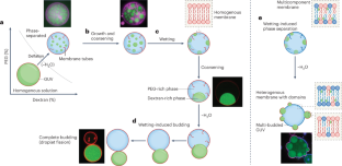
How membranes influence intracellular phase separation
- Rumiana Dimova ORCID: orcid.org/0000-0002-3872-8502 1
Nature Chemistry volume 16 , pages 10–11 ( 2024 ) Cite this article
3566 Accesses
9 Altmetric
Metrics details
- Membrane biophysics
Liquid–liquid phase separation (LLPS) within cells is a captivating phenomenon known to aid the organization of cellular components; however, its complex kinetics have remained a puzzle. Now, a new study elucidates the crosstalk between the phase state of an encapsulating membrane and LLPS dynamics.
This is a preview of subscription content, access via your institution
Access options
Access Nature and 54 other Nature Portfolio journals
Get Nature+, our best-value online-access subscription
24,99 € / 30 days
cancel any time
Subscribe to this journal
Receive 12 print issues and online access
251,40 € per year
only 20,95 € per issue
Buy this article
- Purchase on Springer Link
- Instant access to full article PDF
Prices may be subject to local taxes which are calculated during checkout
Jones, R. A. L., Norton, L. J., Kramer, E. J., Bates, F. S. & Wiltzius, P. Phys. Rev. Lett. 66 , 1326–1329 (1991).
Article CAS PubMed Google Scholar
Crowe, C. D. & Keating, C. D. Interface Focus 8 , 20180032 (2018).
Article PubMed PubMed Central Google Scholar
Dimova, R. & Lipowsky, R. Adv. Mater. Interfaces 4 , 1600451 (2017).
Article Google Scholar
Su, W.-C. et al. Nat. Chem. https://doi.org/10.1038/s41557-023-01267-1 (2023).
Article PubMed Google Scholar
Alberti, S., Gladfelter, A. & Mittag, T. Cell 176 , 419–434 (2019).
Article CAS PubMed PubMed Central Google Scholar
Babl, L., Merino-Salomón, A., Kanwa, N. & Schwille, P. Sci. Rep. 12 , 17949 (2022).
Article CAS PubMed Central Google Scholar
Mangiarotti, A., Chen, N., Zhao, Z., Lipowsky, R. & Dimova, R. Nat. Commun. 14 , 2809 (2023).
Mangiarotti, A. et al. Nat. Commun. 14 , 6081 (2023).
Wang, H.-Y. et al. Sci. Adv. 9 , eadf6205 (2023).
Download references
Author information
Authors and affiliations.
Max Planck Institute of Colloids and Interfaces, Science Park Golm, Potsdam, Germany
Rumiana Dimova
You can also search for this author in PubMed Google Scholar
Corresponding author
Correspondence to Rumiana Dimova .
Ethics declarations
Competing interests.
The author declares no competing interests.
Rights and permissions
Reprints and permissions
About this article
Cite this article.
Dimova, R. How membranes influence intracellular phase separation. Nat. Chem. 16 , 10–11 (2024). https://doi.org/10.1038/s41557-023-01407-7
Download citation
Published : 27 December 2023
Issue Date : January 2024
DOI : https://doi.org/10.1038/s41557-023-01407-7
Share this article
Anyone you share the following link with will be able to read this content:
Sorry, a shareable link is not currently available for this article.
Provided by the Springer Nature SharedIt content-sharing initiative
Quick links
- Explore articles by subject
- Guide to authors
- Editorial policies
Sign up for the Nature Briefing newsletter — what matters in science, free to your inbox daily.

- Architecture and Design
- Asian and Pacific Studies
- Business and Economics
- Classical and Ancient Near Eastern Studies
- Computer Sciences
- Cultural Studies
- Engineering
- General Interest
- Geosciences
- Industrial Chemistry
- Islamic and Middle Eastern Studies
- Jewish Studies
- Library and Information Science, Book Studies
- Life Sciences
- Linguistics and Semiotics
- Literary Studies
- Materials Sciences
- Mathematics
- Social Sciences
- Sports and Recreation
- Theology and Religion
- Publish your article
- The role of authors
- Promoting your article
- Abstracting & indexing
- Publishing Ethics
- Why publish with De Gruyter
- How to publish with De Gruyter
- Our book series
- Our subject areas
- Your digital product at De Gruyter
- Contribute to our reference works
- Product information
- Tools & resources
- Product Information
- Promotional Materials
- Orders and Inquiries
- FAQ for Library Suppliers and Book Sellers
- Repository Policy
- Free access policy
- Open Access agreements
- Database portals
- For Authors
- Customer service
- People + Culture
- Journal Management
- How to join us
- Working at De Gruyter
- Mission & Vision
- De Gruyter Foundation
- De Gruyter Ebound
- Our Responsibility
- Partner publishers
Your purchase has been completed. Your documents are now available to view.
Analysis of ethanol dehydration using membrane separation processes
After the biomass pretreatment and fermentation processes, the purification step constitutes a major task in bioethanol production processes. The use of membranes provides an interesting choice to achieve high-purity bioethanol. Membrane separation processes are generally characterized by low energy requirements, but a high capital investment. Some major design aspects for membrane processes and their application to the ethanol dehydration problem are addressed in this work. The analysis includes pervaporation and vapor permeation methods, and considers using two types of membranes, A-type zeolite and amorphous silica membrane. The results identify the best combination of membrane separation method and type of membrane needed for bioethanol purification.
1 Introduction
Because of the high purity required for bioethanol for several applications, including its use as fuel, the dehydration step represents a major challenge in its production process. One problem with this purification step is the azeotrope for the ethanol-water mixture that requires a special separation process. One option worth of consideration is the use of membrane separation arrangements to carry out such ethanol purification process, for which two methods are typically considered, namely pervaporation and vapor permeation. Several characteristics of membrane separation processes are first described, followed by a review on reported works for ethanol dehydration using membranes.
The difference between the pervaporation (PV) and vapor permeation (VP) separation processes relies on the feed condition, liquid for PV and vapor for VP. The feed stream side is at high pressure, while the other side is at low pressure, producing a low-pressure vapor. The vapor generated is called permeate, while the stream that remains in the feed side is known as retentate. Figure 1 shows the two processes. Although the mass transport phenomena through the membrane are not totally well known, the solution-diffusion model is frequently adopted, because it has been shown to provide good approximations for the behavior of membrane separation systems [ 1 , 2 ]. Some variations of the model have also been developed [ 3 , 4 , 5 , 6 ].

Pervaporation and vapor permeation representation
Important applications of PV and VP for solvent dehydration using hydrophilic membranes have been reported [ 7 , 8 , 9 , 10 ]. Also, the organic mixture separation has started to be reported as an application area of these methods [ 11 , 12 ]. The success of their industrial implementation strongly depends on the membrane materials. Although the membrane separation started at the end of 1960 with reverse osmosis, it was not until 1980 when the first industrial application for gas separation mixture was implemented, due to the start of serial production of commercial polymeric membranes [ 13 , 14 ]. Polymeric membranes have been successfully applied; however, its intrinsic limitations, such as low temperature and mechanic resistance excluded its use for several applications. More recently, inorganic membranes have been used; they can operate at higher temperatures and show better mechanic resistance than polymeric membranes, but they are generally more expensive [ 15 , 16 ].
Membrane separations are used for azeotropic or very close boiling point mixtures when conventional processes, such as distillation, adsorption or absorption, need high energy consumption or complex configurations. However, in order to avoid high area requirements it is convenient to combine membrane separation methods with conventional separation processes; several works have addressed this approach through the integration of distillation and membrane separation systems [ 17 , 18 , 19 , 20 , 21 ]. Design methods applied as part of optimization models for hybrid distillation-pervaporation and distillation-vapor permeation systems have also been reported [ 22 , 23 , 24 , 25 ]. Other configurations have been recently considered, such as the use of nano-filtration membranes [ 26 ], the integration of solar-driven membranes with distillation [ 27 ], and the novel development of membrane bioreactors [ 28 , 29 , 30 ].
One of the limitations of ethanol fuel production from removable sources is the high purity required because of the need for a costly separation process [ 31 , 32 , 33 ]. Distillation followed by a membrane module can be considered to reduce the ethanol purification cost [ 22 , 33 , 34 , 35 , 36 ]. The membrane module can operate in pervaporation or vapor permeation fashion. Several questions have to be answered in order to implement these hybrid processes, including the selection of the best option (PV or VP), operating conditions, and type of membrane to be used. In this work, we address these items through a systematic methodology. Our analysis involved the PV and VP processes and two types of inorganic and hydrophilic membranes, the A-type zeolite and amorphous silica.
2 Methodology
A membrane model (MM) was developed and implemented into the Matlab environment to calculate the area requirements for PV and VP systems. The MMs involved the solution of the mass and energy balance for the membrane. We assumed that the feed stream to the membrane is the distillate from a binary column; then, the simulation of ethanol-water mixture distillation was implemented in Aspen plus in order to get the distillate conditions, which become the MM input data. A membrane area sensitive analysis was developed by varying the feed pressure and the permeate pressure on the membrane. A general methodology representation is shown in Figure 2 .

General methodology
2.1 Input data from distillation simulations
A conventional distillation column was implemented into Aspen plus, using RadFrac subroutine and the NRTL thermodynamic model. The column feed was defined as a saturated liquid of an ethanol-water mixture with a molar flow of 140.45 Kmol/hr and 0.3316 ethanol mol composition (> 50 wt%). For the distillate stream the ethanol recovery and purity were input as design specifications with 99.09% and 92.01% (81.81% mol) purity, based on initial ethanol mass flow. These conditions are below the azeotropic composition. The mass reflux ratio and mass distillate rate were set as process parameters. The distillation column was set with 15 equilibrium stages, with feed in tray 12. A total condenser was used to get the PV input data and a partial condenser was used to get the VP input data. A schematic representation is shown in Figure 3 .

Condenser options, a) total condenser before PV; b) partial condenser before VP
In order to get the distillate conditions at different pressures, a set of pressure condensers was defined. Table 1 shows the pressure and the distillate temperatures for the PV and VP processes; for the PV process the liquid enthalpy is required. The distillate molar flow was 56.5 Kmol/hr with 0.8181 ethanol mol composition, for all cases.
Results for distillate stream (membrane input data)
2.2 Membrane model
The membrane separation section shown in Figure 4 was considered. For the VP method only one separation section was required, with five membrane modules and a maximum area for each module of 500 m 2 . In the case of the PV method more than one separation section could be required; in this case, a heat exchanger was needed between the two separation sections. Each section had five membrane modules with a maximum area of 100 m 2 , and up to 10 sections.

Membrane section arrangement
The total distillate flow was divided into five equal sub-streams, one for each module, with an individual flow of 11.3 Kmol/hr.
2.2.1 Modeling equations
Pervaporation and vapor permeation processes can be described by the solution-diffusion model [ 1 , 2 ], but they have different driving forces. In the VP case, since the two side of membrane are in the vapor phase, the driving force was defined as a partial pressure difference. For PV processes, Wijmans and Baker [ 2 ] proposed the driving force as a vapor pressure difference. Therefore, the equation (1) defines the molar flux, J i , through the membrane for the VP method and equation (2) gives the molar flux for the PV process.
The permeance ( Q i ) is a property for each component in one kind of membrane, which relates the permeability coefficient and the membrane thickness. According to Sommer and Melin [ 10 ], for A-type zeolite and amorphous silica membrane the permeance can be estimated as a temperature function using the following relation,
where the reference temperature ( T ref ) is 80°C, and the parameters Q i,ref and E i have to be known for each component. The values for the ethanol-water system that were reported by Sommer and Melin [ 10 ] were used in this work.
In order to find the permeate and the retentate flows, output compositions, and in the PV case the temperature drop through the membrane, a differential equation model was used, with variables expressed as a function of the membrane area. The model is based on the shortcut method proposed by Bausa and Marquardt [ 19 ].
In the VP process, no latent heat is required in the transport of the components because there is not a phase change; then, the temperature drop through the module was neglected [ 18 ]. For the VP case, only a mass balance is required. Equation (4) gives the vapor flow change in the retentate, equation (5) the mol fraction change for each component for the retentate side, while equation (6) relates the permeate composition with the total flux and component flux.
The boundary conditions are:
In the PV process there is a phase change through the membrane; the energy required comes from the liquid in the retentate side. An enthalpy change in the liquid phase gives a temperature drop through the membrane module. The temperature drop reduces the mass transfer through the membrane; therefore, it is required to re-heat the retentate stream between two modules in order to achieve the desired separation. Mass and energy balance must be solved simultaneously. The following equations represent the PV model. Equations (11) and (12) give the liquid flow and component composition change for the retentate stream, while equation (13) gives the enthalpy change for the liquid.
In order to solve equation (13) , liquid and vapor enthalpies for ideal mixtures were assumed [ 37 ].
Using equations (20) and (21) , one can write the energy balance with Equation (13) for a binary system as,
The PV model assumes a saturate vapor phase on feed side; then, the equilibrium condition between the liquid phase and the saturate vapor is given by y i = k i x i . On the order hand, the composition is close to the azeotropic condition; therefore, k i values are close 1.0 and it can be assumed that y i ‒x i ≈0. Applying this condition to equation (22) , one obtains,
Equation (23) was used to solve the liquid enthalpy change for the PV process.
2.2.2 Matlab structure
The membrane model was solved aided by Matlab for each the PV and VP cases. Figures 5 and 6 show the algorithm implemented in order to solve the balances for the membrane modules.

Matlab algorithm to solve the PV system

Matlab algorithm to solve the VP system
In the MM for PV ( Figure 5 ) three cycles were used, the first one solves the balances for one module, the second one solves the balances for several modules and the last one gets the solutions for a set of permeate pressure conditions. The feed pressure conditions were manually changed for each run. Three physical restrictions were used to stop the first cycle. First, if the ethanol mol composition is equal or higher than 0.9874, the total area required has been found and a new run is started for a new permeate pressure condition. Second, a maximum drop temperature for one module was defined as 10 K; if the temperature drop is equal or higher than this value, the balances are solved in a new module. Finally, the maximum area for one module was defined as 100 m 2 ; when this value is reached in one module without achieving the target composition, a new module is needed to continue the solution process.
The logic used in VP MM ( Figure 6 ) was similar to PV MM. Three cycles were also used, the first one solves the balances for one module, the second one gets the solution for a set of permeate pressures and the last one gets the solution for a set of feed pressures. In the VP case, only one membrane section was used, with not re-heat required for the retentate stream. Table 2 shows the input and output data for the MM for each system.
Input and output data for MM in Matlab
3 Results and Discussion
3.1 a-type zeolite results.
Table 3 shows the membrane area required and number of modules for the PV method. The first table column shows the permeate pressure and the first table row shows the feed pressure (retentate pressure). For the PV case, when the number of modules was higher than 10, areas were not reported. Table 4 shows the area required for the VP method, using the A-type zeolite membrane. In the VP case, when the area required for one module was higher than 500 m 2 (higher than 2500 for section), areas were not reported.
Area (m 2 ) and modules (area/ modules) required for A-type zeolite membrane using the PV method
Area (m 2 ) required for A-type zeolite membrane using the VP method
According to these results, high pressure differences are needed in order to achieve low areas values. In general, the VP method needs lower areas than the PV method; moreover, re-heating the retentate stream for the VP method is not needed.
3.2 Amorphous silica membrane results
Table 5 gives the areas and number of modules for the PV method, while Table 6 shows the results for the VP case using the amorphous silica membrane. For this kind of membrane, lower areas are also required with the VP method. Lower areas are obtained using the amorphous silica membrane than using the A-type zeolite membrane.
Area (m 2 ) and modules (area/ modules) required for amorphous silica membrane using the PV method
Area (m 2 ) required for amorphous silica membrane using the VP method
3.3 Comparison between A-type zeolite membrane and amorphous silica membrane
In this section, the VP results for the two types of membranes were plotted in order to compare the membrane performances. Figure 7 shows the two membrane plots (the flat zone in Figure 7 corresponds to the areas not reported). It can be observed that A-type zeolite membrane has a higher sensitivity to delta pressure decrease than amorphous silica membrane. This means that amorphous silica membrane can operate with lower feed pressure and higher permeate pressure, which provides lower operation costs.

Membrane area required as a function of pressure differential
Figure 8 shows the ethanol mass flow leaving with the permeate stream for the two types of membranes using the VP method. It can be observed that the mass flow performance is similar to the area performance; however, for higher pressure differences the A-type zeolite gives lower ethanol mass flows in the permeate. These results agree with the fact that the A-type zeolite is a more selective membrane than the amorphous silica membrane. Moreover, it can be inferred that silica membranes will need to operate with a permeate recycle to the distillation column, while for A-type zeolite membranes use the recycle implementation could be not necessary.

Ethanol mass flow in permeate stream
Finally, in order to select the permeate pressure, the bubble point temperature for the permeate stream should be taken into account. Since the low-pressure vapor stream in the permeate needs to be condensed, it will be convenient to use cooling water instead of a refrigerant. Based on the permeate composition, we estimated the bubble point temperature. The results are reported in Figure 9 for the VP method using the two membranes. The bubble point using the PV method was also estimated, and the performance was very similar to the use of VP. It can be observed that the bubble point temperature only depends on the permeate pressure. Based on these results, permeate pressures higher than 0.08 bar for A-type zeolites and higher than 0.13 bar for amorphous silica membranes are recommended. Table 7 resumes the best operation conditions for each case. The lower area values were chosen with the restriction of using cooling water for the permeate condensation.

Results for the VP method using the two membranes
Best operation conditions selected for each case
The results of this work show that if membrane processes are considered, the use of the VP method using an amorphous silica membrane with a recycle of the permeate stream provides an excellent option for ethanol purification.
4 Conclusions
The use of membrane separation systems for ethanol dehydration has been presented. A systematic methodology was developed in order to determine the feed and permeate pressure influence on the PV and VP methods for the production of high-purity ethanol. A-type zeolites and amorphous silica membranes were considered. Relevant factors such as total area requirements and membrane output conditions were determined with this procedure. As a result, the best operating conditions for the membrane separation process were identified. Based on the results, the use of VP method with amorphous silica membrane is recommended for the dehydration of bioethanol.
Conflict of interest : Authors state no conflict of interest.
Nomenclature
Molar flux through the membrane, Kmol/ m 2 h
Permeace coefficient, Kmol/ m 2 h bar
Mole fraction in feed side
Mole fraction in permeate side
Feed pressure, bar
Permeate pressure, bar
Saturation pressure at liquid conditions, bar
Activity coefficient
[1] Wijmans JG. The role of permeant molar volume in the solution-diffusion model transport equations, Journal of Membrane Science, 2004, 237, 39-50. 10.1016/j.memsci.2004.02.028 Search in Google Scholar
[2] Wijmans JG, Baker RW. A simple predictive treatment of the permeation process in pervaporation, Journal of Membrane Science, 1993, 79, 101-113. 10.1016/0376-7388(93)85021-N Search in Google Scholar
[3] Schaetzel P, Vauclair C, Nguyen QT, Bouzerar R. A simplified solution–diffusion theory in pervaporation: the total solvent volume fraction model, Journal of Membrane Science, 2004, 244, 117-127. 10.1016/j.memsci.2004.06.060 Search in Google Scholar
[4] Schaetzel P, Bouallouche R, Aït Amar H, Nguyen QT, Riffault B, Marais S. Mass transfer in pervaporation: The key component approximation for the solution-diffusion model, Desalination, 2010, 251, 161-166. 10.1016/j.desal.2009.09.132 Search in Google Scholar
[5] Bettens B, Verhoef A, van Veen HM, Vandecasteele C, Degrève J, Van der Bruggen B. Pervaporation of binary water–alcohol and methanol–alcohol mixtures through microporous methylated silica membranes: Maxwell–Stefan modeling, Computers & Chemical Engineering, 2010, 34, 1775-1788. 10.1016/j.compchemeng.2010.03.014 Search in Google Scholar
[6] Krishna R, van Baten JM. Highlighting pitfalls in the Maxwell-Stefan modeling of water-alcohol mixture permeation across pervaporation membranes, Journal of Membrane Science, 2010, 360, 476-482. 10.1016/j.memsci.2010.05.049 Search in Google Scholar
[7] Chapman PD, Oliveira T, Livingston AG, Li K. Membranes for the dehydration of solvents by pervaporation, Journal of Membrane Science, 2008, 318, 5-37. 10.1016/j.memsci.2008.02.061 Search in Google Scholar
[8] Bolto B, Hoang M, Xie Z. A review of water recovery by vapour permeation through membranes, Water Research, 2012, 46, 259-266. 10.1016/j.watres.2011.10.052 Search in Google Scholar PubMed
[9] Sommer S, Melin T. Performance evaluation of microporous inorganic membranes in the dehydration of industrial solvents, Chemical Engineering and Processing: Process Intensification, 2005, 44, 1138-1156. 10.1016/j.cep.2005.02.006 Search in Google Scholar
[10] Sommer S, Melin T. Influence of operation parameters on the separation of mixtures by pervaporation and vapor permeation with inorganic membranes. Part 1: Dehydration of solvents, Chemical Engineering Science, 2005, 60, 4509-4523. 10.1016/j.ces.2005.02.059 Search in Google Scholar
[11] Sommer S, Melin T. Influence of operation parameters on the separation of mixtures by pervaporation and vapor permeation with inorganic membranes. Part 2: Purely organic systems, Chemical Engineering Science, 2005, 60, 4525-4533. 10.1016/j.ces.2005.02.070 Search in Google Scholar
[12] Caballero JA, Grossmann IE, Keyvani M, Lenz ES. Design of Hybrid Distillation−Vapor Membrane Separation Systems, Ind. Eng. Chem. Res., 2009, 48, 9151-9162. 10.1021/ie900499y Search in Google Scholar
[13] Baker RW. Future Directions of Membrane Gas Separation Technology, Industrial & Engineering Chemistry Research, 2002, 41, 1393-1411. 10.1021/ie0108088 Search in Google Scholar
[14] Bernardo P, Drioli E, Golemme G. Membrane Gas Separation: A Review/State of the Art, Industrial & Engineering Chemistry Research, 2009, 48, 4638-4663. 10.1021/ie8019032 Search in Google Scholar
[15] Van Hoof V, Dotremont C, Buekenhoudt A. Performance of Mitsui NaA type zeolite membranes for the dehydration of organic solvents in comparison with commercial polymeric pervaporation membranes, Separation and Purification Technology, 2006, 48, 304-309. 10.1016/j.seppur.2005.06.019 Search in Google Scholar
[16] Van Hoof V, Van den Abeele L, Buekenhoudt A, Dotremont C, Leysen R. Economic comparison between azeotropic distillation and different hybrid systems combining distillation with pervaporation for the dehydration of isopropanol, Separation and Purification Technology, 2004, 37, 33-49. 10.1016/j.seppur.2003.08.003 Search in Google Scholar
[17] Fontalvo J, Cuellar P, Timmer JMK, Vorstman MAG, Wijers JG, Keurentjes JTF. Comparing Pervaporation and Vapor Permeation Hybrid Distillation Processes, Industrial & Engineering Chemistry Research, 2005, 44, 5259-5266. 10.1021/ie049225z Search in Google Scholar
[18] Vane LM, Alvarez FR. Membrane-assisted vapor stripping: energy efficient hybrid distillation–vapor permeation process for alcohol–water separation, Journal of Chemical Technology & Biotechnology, 2008, 83, 1275-1287. 10.1002/jctb.1941 Search in Google Scholar
[19] Bausa J, Marquardt W. Shortcut Design Methods for Hybrid Membrane/Distillation Processes for the Separation of Nonideal Multicomponent Mixtures, Industrial & Engineering Chemistry Research, 2000, 39, 1658-1672. 10.1021/ie990703t Search in Google Scholar
[20] Eumine-Suk D, Matsuura T. Membrane‐Based Hybrid Processes: A Review, Separation Science and Technology, 2006, 41, 595-626. 10.1080/01496390600552347 Search in Google Scholar
[21] Huang Y, Baker RW, Vane LM. Low-Energy Distillation-Membrane Separation Process, Industrial & Engineering Chemistry Research, 2010, 49, 3760-3768. 10.1021/ie901545r Search in Google Scholar
[22] Roth T, Kreis P, Górak A. Process analysis and optimisation of hybrid processes for the dehydration of ethanol, Chemical Engineering Research and Design, 2013, 91, 1171-1185. 10.1016/j.cherd.2013.01.016 Search in Google Scholar
[23] Fontalvo J, Vorstman MAG, Wijers JG, Keurentjes JTF. Separation of Organic−Water Mixtures by Co-current Vapor−Liquid Pervaporation with Transverse Hollow-Fiber Membranes, Industrial & Engineering Chemistry Research, 2006, 45, 2002-2007. 10.1021/ie0510369 Search in Google Scholar
[24] Koch K, Sudhoff D, Kreiß S, Górak A, Kreis P. Optimisation-based design method for membrane-assisted separation processes, Chemical Engineering and Processing: Process Intensification, 2013, 67, 2-15. 10.1016/j.cep.2012.09.013 Search in Google Scholar
[25] Szitkai Z, Lelkes Z, Rev E, Fonyo Z. Optimization of hybrid ethanol dehydration systems, Chemical Engineering and Processing: Process Intensification, 2002, 41, 631-646. 10.1016/S0255-2701(01)00192-1 Search in Google Scholar
[26] Roli FM, Yussof HW, Seman MNA, Saufi SM, Mohammad AW. Separating xylose from glucose using spiral wound nanofiltration membrane: effect of cross-flow parameters on sugar rejection. IOP Conf Ser Mater Sci Eng 2017; 162: 1–6. 10.1088/1757-899X/162/1/012035 Search in Google Scholar
[27] Kumar R, Ghosh AK, Pal P. Fermentative energy conversion: renewable carbon source to biofuels (ethanol) using Saccharomyces cerevisiae and downstream purification through solar driven membrane distillation and nanofiltration. Energy Convers Manag 2017; 150: 545–557. 10.1016/j.enconman.2017.08.054 Search in Google Scholar
[28] Mahboubi A, Ylitervo P, Doyen W, De Wever H, Taherzadeh MJ. Reverse membrane bioreactor: introduction to a new technology for biofuel production. Biotechnol Adv 2016; 34: 954–975. 10.1016/j.biotechadv.2016.05.009 Search in Google Scholar PubMed
[29] Saha K, Maharana A, Sikder J, Chakraborty S, Curcio S, Drioli E. Continuous production of bioethanol from sugarcane bagasse and downstream purification using membrane integrated bioreactor. Catal Today 2017. 10.1016/j.cattod.2017.11.031 Search in Google Scholar
[30] Zahed O, Jouzani GS, Abbasalizadeh S, Khodaiyan F, Tabatabaei M. Continuous co-production of ethanol and xylitol from rice straw hydrolysate in a membrane bioreactor. Folia Microbiol (Praha) 2016; 61: 179–189. 10.1007/s12223-015-0420-0 Search in Google Scholar PubMed
[31] Kiss AA, Suszwalak DJPC. Enhanced bioethanol dehydration by extractive and azeotropic distillation in dividing-wall columns, Separation and Purification Technology, 2012, 86, 70-78. 10.1016/j.seppur.2011.10.022 Search in Google Scholar
[32] Avilés Martínez A, Saucedo-Luna J, Segovia-Hernandez JG, Hernandez S, Gomez-Castro FI, Castro-Montoya AJ. Dehydration of Bioethanol by Hybrid Process Liquid–Liquid Extraction/ Extractive Distillation, Industrial & Engineering Chemistry Research, 2011, 51, 5847-5855. 10.1021/ie200932g Search in Google Scholar
[33] Vane LM. A review of pervaporation for product recovery from biomass fermentation processes, Journal of Chemical Technology & Biotechnology, 2005, 80, 603-629. 10.1002/jctb.1265 Search in Google Scholar
[34] Vane LM, Alvarez FR, Huang Y, Baker RW. Experimental validation of hybrid distillation-vapor permeation process for energy efficient ethanol–water separation, Journal of Chemical Technology & Biotechnology, 2010, 85, 502-511. 10.1002/jctb.2318 Search in Google Scholar
[35] Richter H, Voigt I, Kühnert J-T. Dewatering of ethanol by pervaporation and vapour permeation with industrial scale NaA-membranes, Desalination, 2006, 199, 92-93. 10.1016/j.desal.2006.03.150 Search in Google Scholar
[36] Verhoef A, Degrève J, Huybrechs B, van Veen H, Pex P, Van der Bruggen B. Simulation of a hybrid pervaporation-distillation process, Computers & Chemical Engineering, 2008, 32, 1135-1146. 10.1016/j.compchemeng.2007.04.014 Search in Google Scholar
[37] Seader JD, Henley EJ. Separation process principles, Second ed., USA, John Wiley & Sons, Inc., 1998. Search in Google Scholar
© 2020 Carolina Conde-Mejía, Arturo Jiménez-Gutiérrez published by De Gruyter
This work is licensed under the Creative Commons Attribution 4.0 International License.
- X / Twitter
Supplementary Materials
Please login or register with De Gruyter to order this product.
Journal and Issue
Articles in the same issue.
A Membrane System for the Treatment of Waste Water Containing Organic Compounds
- Published: 28 February 2020
- Volume 51 , pages 272–274, ( 2019 )
Cite this article
- E. Zabolotnaya 1 &
- I. I. Men’shova 2
96 Accesses
Explore all metrics
A combination of the methods of physicochemical purification with membrane purification by microfiltration is considered. Repeated reuse of purified water for dyeing textile materials is investigated.
This is a preview of subscription content, log in via an institution to check access.
Access this article
Price includes VAT (Russian Federation)
Instant access to the full article PDF.
Rent this article via DeepDyve
Institutional subscriptions
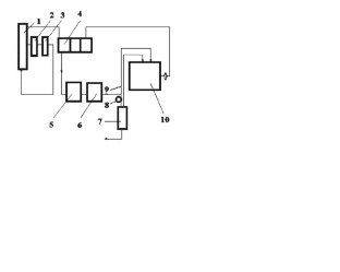
Reagent-free water treatment in the domestic power industry: a myth or a reality.
S. L. Gromov

Membrane Technology for Desalination and Wastewater Recycling

Novel Membrane Technologies in the Treatment and Recovery of Wastewaters
A. A. Svitsov, Introduction to Membrane Technology [in Russian], DeLi print, Moscow (2007) p. 208.
Google Scholar
A. A. Svitsov and O. A. Kostrikova, Semi-Permeable Membranes [in Russian], electronic textbook, RCTU named after D. I. Mendeleev, Moscow (2005) p. 25.
A. A. Svitsov and I. I. Menshova, “Membrane treatment of dyeing wash water for reuse” [in Russian], Mater. All-Russian Sci. Conf. “Membranes – 2007” , A. V. Topchiev Institute of Petrochemical Synthesis, Moscow (2007) p. 122.
I. I. Menshova and A. D. Kostrova, in: Coll. Sci. Works “Technology of finishing and cleaning of textile products” to the 75th anniversary of the Department of Chemical Technology of fibrous materials [in Russian], ed. V. V. Safonov, A. N. Kosygin Moscow State Textile University, Moscow (2009) p. 33-41.
Workshop on Chemical Technology for Finishing Production [in Russian], textbook, ed. V. V. Safonov , A. N. Kosygin Moscow State Textile University, Moscow (2008) p. 595.
A. A. Svitsov, A. Shtogrin, and N. Filimonova, Fundamentals of the Design of Industries Using Membrane Separation [in Russian], RCTU named after D. I. Mendeleev, Moscow (2007) p. 100.
Download references
Author information
Authors and affiliations.
JSC Scientific Center “Small-tonnage Chemistry”, Moscow, Russia
E. Zabolotnaya
D.Mendeleev University of Chemical Technology of Russia, Moscow, Russia
I. I. Men’shova
You can also search for this author in PubMed Google Scholar
Corresponding author
Correspondence to E. Zabolotnaya .
Additional information
Translated from Khimicheskie Volokna, No. 4, pp. 56 – 57, July – August, 2019.
Rights and permissions
Reprints and permissions
About this article
Zabolotnaya, E., Men’shova, I.I. A Membrane System for the Treatment of Waste Water Containing Organic Compounds. Fibre Chem 51 , 272–274 (2019). https://doi.org/10.1007/s10692-020-10093-x
Download citation
Published : 28 February 2020
Issue Date : November 2019
DOI : https://doi.org/10.1007/s10692-020-10093-x
Share this article
Anyone you share the following link with will be able to read this content:
Sorry, a shareable link is not currently available for this article.
Provided by the Springer Nature SharedIt content-sharing initiative
- Find a journal
- Publish with us
- Track your research
The removal of CO2 and N-2 from natural gas: A review of conventional and emerging process technologies
Author: rufford, t. e., author: smart, s., author: watson, g. c. y., author: graham, b. f., author: boxall, j., author: diniz da costa, j. c., author: may, e. f..
This article provides an overview of conventional and developing gas processing technologies for CO2 and N-2 removal from natural gas. We consider process technologies based on absorption, distillation, adsorption, membrane separation and hydrates. For each technology, we describe the fundamental separation mechanisms involved and the commonly applied process flow schemes designed to produce pipeline quality gas (typically 2% CO2, <3% N-2) and gas to feed a cryogenic gas plant (typically 50 ppmv CO2, 1% N-2). Amine absorption technologies for CO2 and H2S removal (acid gas treating) are well-established in the natural gas industry. The advantages and disadvantages of the conventional amineand physical-solvent-based processes for acid gas treating are discussed. The use of CO2 selective membrane technologies for bulk separation of CO2 is increasing in the natural gas industry. Novel low-temperature CO2 removal technologies such as ExxonMobil's Controlled Freeze Zone (TM) process and rapid cycle pressure swing adsorption processes are also emerging as alternatives to amine scrubbers in certain applications such as for processing high CO2 concentration gases and for developing remote gas fields. Cryogenic distillation remains the leading N-2 rejection technology for large scale (feed rates greater than 15 MMscfd) natural gas and liquefied natural gas plants. However, technologies based on CH4 selective absorption and adsorption, as well as N-2 selective pressure swing adsorption technologies, are commercially available for smaller scale gas processing facilities. The review discusses the scope for the development of better performing CO2 selective membranes, N-2 selective solvents and N-2 selective adsorbents to both improve separation power and the durability of the materials used in novel gas processing technologies. (C) 2012 Elsevier B.V. All rights reserved.
Maintenance work is planned for Wednesday 1st May 2024 from 9:00am to 11:00am (BST).
During this time, the performance of our website may be affected - searches may run slowly and some pages may be temporarily unavailable. If this happens, please try refreshing your web browser or try waiting two to three minutes before trying again.
We apologise for any inconvenience this might cause and thank you for your patience.

Chemical Communications
Vertically-stacked mxene/rgo composite membrane for highly efficient h2/co2 separation.
A vertically-stacked MXene/rGO composite membrane with ultrashort transport channels is reported here, which demonstrated outstanding molecular sieving, i.e., H2/CO2 selectivity of up to 83 together with high H2 permeance of 2.7·10-7 mol m-2 s-1 Pa-1 at 120 oC, highlighting its applicability for H2/CO2 separation in CO2 capture and sequestration.
Supplementary files
- Supplementary information PDF (2478K)
Article information
Download citation, permissions.
Z. Dong, Y. Fan, X. Meng, Y. Jin, J. Song, X. Wang, N. Yang, J. Sunarso and S. Liu, Chem. Commun. , 2024, Accepted Manuscript , DOI: 10.1039/D4CC00481G
To request permission to reproduce material from this article, please go to the Copyright Clearance Center request page .
If you are an author contributing to an RSC publication, you do not need to request permission provided correct acknowledgement is given.
If you are the author of this article, you do not need to request permission to reproduce figures and diagrams provided correct acknowledgement is given. If you want to reproduce the whole article in a third-party publication (excluding your thesis/dissertation for which permission is not required) please go to the Copyright Clearance Center request page .
Read more about how to correctly acknowledge RSC content .
Social activity
Search articles by author.
This article has not yet been cited.
Advertisements
COMMENTS
plication to gas separation, pervaporation, and reverse osmosis case studies. Simulation results for these systems show excellent agreement with published experimental data. The thesis also introduces an optimal design strategy for membrane separation systems. This strategy is characterised by two main features: firstly, detailed models are used.
Membrane separation has gained significant interest from the chemical industry due to their compactness, energy efficiency, and modularity. Recent trends in process intensification also emphasizes the importance of a more widespread adoption of membrane-based processes for significant cost savings and sustainable operation. We present a prototype software framework for the automated design ...
A membrane reactor is a combination of chemical conversion and membrane separation process. The membrane reactor acts as a contactor and separates the reaction medium in one chamber from a second chamber containing a catalyst, enzymes, or a cell culture. The simulation of membrane reactors by various configurations is an emerging area.
Membrane technology has undergone a long, historical development in laboratory research and achieved its first major industrial application in the 1960s [].Membrane is a kind of material with a selective separation function, and can transfer one component and restrict others because of the special properties of the components [].The main membrane technologies include microfiltration ...
fluids. MF membrane has pore sizes ranging from 0.1 to 10.0 mm, through which micro-organisms cannot pass. As a result, microfilters can be used to disinfect water solutions. For Retentate/Concentrate Permeate Membrane Module Feed Fig. 7.2. Basic diagram of a membrane separation system. Polymeric membranes Ceramic membranes Fig. 7.1.
Mathematical modelling of membrane separation Vinther, Frank Publication date: 2015 Document Version Publisher's PDF, also known as Version of record Link back to DTU Orbit Citation (APA): Vinther, F. (2015). Mathematical modelling of membrane separation. ... Furthermore, the thesis consist of three separate mathematical models, each
1 Introduction: Membrane Separations Today. Membranes are usually considered as the third wave of separation processes, thermal separations (e.g., distillation, evaporation) and auxiliary phase processes (e.g. absorption, liquid extraction, adsorption) being the first and second respectively (King, 1980; Koros, 2001).The industrial development of membrane indeed demanded advanced thin layer ...
The work of this thesis focuses on membrane technology for gas separation due to the merit of high energy efficiency relative to conventional techniques. Advanced polymers with high fractional free volume and highly porous nanoparticles with full organic framework are selected to fabricate mixed matrix membranes (MMMs). Efforts to further improve MMMs gas separation performance include solvent ...
In this thesis, four membrane technologies were used to promote resources recovery, including water, depending on the valorization way of the concentrated stream: electrodialysis (ED) was used for its concentration, nanofiltration ... Integration of electrically driven membrane separation processes for water treatment and resources recovery 3 ...
chemical features have made these materials of significant interest for membrane-based gas separations. Mixed-matrix membranes (MMMs) formed by incorporating MOF particles into polymers have attracted significant attention because these composite systems can potentially surpass the separation performance of pure polymers alone.
Pervaporation is a membrane separation process used in the separations of mixtures, such as water-organic , organic-water or organic-organic . In the pervaporation separation, a membrane acts as the separating barrier for the component of minor affinity. ... Noriega M.A. Master's Thesis. Universidad Nacional de Colombia; Bogotá ...
Mathematical Description of Mass Transport in Membrane Processes. 2.5. Membrane Separation Capability. 2.6. Chemical and Electrochemical Equilibrium in Membrane Processes. 2.6.1. Osmotic Equilibrium, Osmotic Pressure, Osmosis, and Reverse Osmosis. 2.6.2. Donnan Equilibrium and Donnan Potential. 3. Principles.
Compared with current conventional technologies, oxygen/nitrogen (O 2 /N 2 ) separation using membrane offers numerous advantages, especially in terms of energy consumption, footprint, and capital cost. However, low product purity still becomes the major challenge for commercialization of membrane-based technologies. Therefore, numerous studies on membrane development have been conducted to ...
In industrial membrane plants the membrane area of 100,000 m 2 is required to perform an effective separation. Basically, the problem is how can one pack the most area of membranes into the least volume, to minimize the cost of the containment vessel consistent with providing acceptable flow hydrodynamics in the vessel.
The researchers observed lateral phase separation into membrane domains (Fig. 1e ), driven by mechanical and chemical factors influenced by droplet wetting. The intriguing phenomenon of LLPS ...
-selective membranes and separation processes. The MEEP-based membrane processes have been shown to produce at least 42% less equivalent CO 2 ... I would also like to thank my thesis advisor, Dr. Haiyan Zhao, for her continuous support, guidance, and mentorship, without which I would not have been able to complete my master's degree ...
Membrane-based CO 2 separation that uses semipermeable membranes to selectively remove CO 2 from gas mixture is gaining increasing attention due to the urgent need to reduce greenhouse gas emissions and combat climate change (1-3).Compared to traditional separation methods, this technology has multiple benefits such as lower energy consumption, reduced capital and operating costs, and ...
The Membrane Separation Processes (MSP) can be classed based on the membrane pore size and the particles retained. The microfiltration membranes (MF) have pores in the range of 10 −7 to 10 −5 m (0,1 to 10 µm) diameter and can retain microorganisms and suspended and colloidal particles (Wen-Qiong et al., 2019).
2.2 Membrane model. The membrane separation section shown in Figure 4 was considered. For the VP method only one separation section was required, with five membrane modules and a maximum area for each module of 500 m 2.In the case of the PV method more than one separation section could be required; in this case, a heat exchanger was needed between the two separation sections.
The described features configure membrane separation as more suitable for pipeline specification upgrade than LNG applications. The main drawback of polymer membranes is chemical stability, consisting in CO 2 induced plasticization, which leads to selectivity loss [43]. Performances of inorganic membranes are discussed in [39]. These membranes ...
At the present stage, wastewater treatment may inc lude the use of membrane elements. Membrane technology has the following advantages: separation can be performed continuously; energy costs are generally lo w; membrane processes are easily combined with other separation processes; the introduction of any additives is not required; separation ...
As an emerging zero-dimensional nano crystalline porous material, porous organic cages (POCs) with soluble properties in organic solvents, are promising candidates as molecular fillers in mixed matrix membranes (MMMs). The pore structure of POCs should be adjusted to trigger efficient gas separation performance, and the interaction between filler and matrix should be optimized. In this work ...
Mechanically-robust nanocomposite membranes have been developed via crosslinking chemistry and electrospinning technique based on the rational selection of dispersed phase materials with high Young's modulus (i.e., graphene and multiwalled carbon nanotubes) and Cassie-Baxter design and used for oil and water separation. Proper selection of dispersed phase materials can enhance the stiffness of ...
This article provides an overview of conventional and developing gas processing technologies for CO2 and N-2 removal from natural gas. We consider process technologies based on absorption, distillation, adsorption, membrane separation and hydrates. For each technology, we describe the fundamental separation mechanisms involved and the commonly applied process flow schemes designed to produce ...
In contrast, environmentally friendly separation membranes are required for oily wastewater treatment. In this regard, we fabricated underwater superoleophobic membrane based on β-cyclodextrin and acrylamide for efficient and effective water-oil separation. Acrylamide polymeric membrane was prepared by free radical co-polymerisation by ...
This review highlights various aspects of current palladium membrane research and serves as a comprehensive bibliography covering palladium membrane preparation methods and applications. There are…. Expand. 583. Semantic Scholar extracted view of "THE SEPARATION OF GASES BY MEANS OF POROUS MEMBRANES (thesis)" by H. E. Huckins et al.
A vertically-stacked MXene/rGO composite membrane with ultrashort transport channels is reported here, which demonstrated outstanding molecular sieving, i.e., H2/CO2 selectivity of up to 83 together with high H2 permeance of 2.7·10-7 mol m-2 s-1 Pa-1 at 120 oC, highlighting its applicability for H2/CO2 separation in CO2 capture and sequestration.
Oil spills and micropollutants have become thorny environmental issues, posing serious threat to ecosystem and human health. To settle such dilemma, this study successfully constructed a robust and environmentally-friendly MOFs-COFs hybrid-based membrane (FS-50/COF(MATPA)-MOF(Zr)/PDA@PVDF) for the first time through solution synthesis and solvothermal method, combined with surface modification ...
Thesis: "Computer Simulation of Gas Membrane Separation" Received the prizes for the dissertation research in Moscow Research competition and at the International symposium of membrane technology