
Halley VI Antarctic Research Station
Halley VI, on the freezing, floating Brunt Ice Shelf in Antarctica, is the world’s first fully relocatable Polar research station, and was designed to provide a home from home for scientists working in one of the most extreme environments on earth. It is operated by the British Antarctic Survey (BAS).
The modular design concept for Halley VI was developed in response to the fragile environment and extreme climate. Temperatures drop to -69ºF in winter, winds in excess of 100mph are regular and the site receives almost 5 feet of snow per annum, which never melts. The client’s brief was to design a science research station:
- To be relatively easy to deliver to site, build, operate and ultimately decommission
- To allow for the replacement of individual facilities without significant interference to the whole station.
- To minimise through-life environmental impact from construction to decommissioning with energy efficiency, reduced water usage and an improved waste management strategy.
- To create an ergonomic home from home to support 16 people in the 9-month austral winter and 52 in the 3-month austral summer within a building which is safe, comfortable and stimulating to live in.
- To provide flexibility to support a 5-yearly science programme in a building with a minimum life of 20 years.
- To be fully relocatable inland when there is risk of the site calving off as an iceberg.
- To minimise snow management and allow the station to climb above the annually rising snow levels.
Bedrooms, laboratories, office areas and energy centres are housed in standardised blue modules. A larger two-storey light-filled red module provides the social heart of the station and is used for living, dining and recreation.
The station is arranged in a straight line perpendicular to the prevailing wind so that snow drifts form on the leeward side. This leaves the windward side free from drifts, reducing snow management requirements and creating a hard icy surface across which vehicles can easily move. The base is split in two for life safety. Each half has its own energy centre and is self-sustaining in case of emergency. A bridge link allows sharing of power, drainage and water. The modules are supported on giant steel skis and hydraulically driven legs that allow the station to mechanically ‘climb’ up out of the snow every year. And as the ice shelf moves out towards the ocean, the modules can be lowered and towed by bulldozers further inland, and eventually taken apart when the time comes.
Inspiring interior design provides an uplifting environment to sustain the crew through the long dark winters. Halley VI incorporates medical operating facilities, air traffic control systems and CHP power plants and is a microscopic self-supporting infrastructure-free community. Bedrooms were designed to be comfortable, but not so comfortable as to erode the sense of community. A quiet room has been included at the north end of the station to provide a space for smaller groups to contemplate the majestic icescape outside. A spiral stair leading to the upper level of the red module used for living, dining and recreation is lined in Lebanese cedar panels, which give off a pleasant natural scent in a place where there are no plants, and a colour psychologist was employed to develop a special colour palette to help combat the debilitating influence of Seasonal Affected Disorder.
The modules are constructed with a robust steel structure and clad in highly insulated composite GRP panels. Prefabrication of structure, cladding, rooms and services was maximised within the limitations of the sea ice. Products were sourced from all over the world with the centre of pre-construction activities in South Africa, where full scale trial erection of modules was undertaken prior to shipping to Antarctica by ice-strengthened cargo ship. The modules were erected over three 12-week summer seasons using a factory line approach at Halley V, which was used to support the construction crew. Once they were fully clad, the modules were moved 10 miles inland to the Halley VI site, proving the relocation strategy. Fit out was completed in the final fourth season.
Following completion of the station, Hugh Broughton Architects collaborated with the client on the development of a Post Occupancy Evaluation strategy. Questionnaires were prepared with assistance from space architects at the University of Vienna, using techniques developed for the European Space Agency for assessing human resilience on future missions to the moon and Mars. Results from the first full winter were extremely positive whilst also instigating some minor changes to furniture configuration and station management protocols.
The highly adaptable project has won 15 international awards, including Architizer’s Global Project of the Year 2014.

Project Year
Team members.
Client | British Antarctic Survey Architects | Hugh Broughton Architects Multi-disciplinary consultants | AECOM Main contractor | Galliford Try International Cladding consultant | Billings Design Associates Colour psychologist | Colour Effects
Photos | James Morris, British Antarctic Survey
Further Information
https://hbarchitects.co.uk/halley-vi-british-antarctic-research-station/
© 7-t_Central module isometric view
© james morris – social module, © james morris – social module exterior, © james morris – returning to halley vi, © james morris – halley vi, © james morris – halley vi in the mist, © james morris – halley vi from the north, © james morris – halley vi bedroom, © bas – halley vi.
Images courtesy of NASA, ESA, SpaceX, DLR, Liquifer Systems Group, SEArch+
© Copyright 2024 SpaceArchitect.org. All Rights Reserved. Website by XTEND Design London

- Design Objectives
- Building Types
- Space Types
- Design Disciplines
- Guides & Specifications
- Resource Pages
- Project Management
- Building Commissioning
- Operations & Maintenance
- Building Information Modeling (BIM)
- Unified Facilities Guide Specifications (UFGS)
- Unified Facilities Criteria (UFC)
- VA Master Specifications (PG-18-1)
- Design Manuals (PG-18-10)
- Department of Energy
- General Services Administration
- Department of Homeland Security
- Department of State
- Course Catalog
- Workforce Development
- Case Studies
- Codes & Standards
- Industry Organizations
Interior Design for Research Facilities
by Grace Paul and Dan Watch Excerpted from Building Type Basics for Research Laboratories, Second Edition
- Introduction
Within This Page
Additional resources.
Today's leading-edge research facilities speak of the importance and excitement of the research work. The design of a research center can significantly impact productivity , as well as the recruitment, morale and retention of researchers and staff. The laboratories are where researchers concentrate their time, and the environment speaks volumes about the perceived value of the work and the people who do it.
Beyond being highly functional in service of the research, the most successful facilities are welcoming, inspiring, educational, easy to navigate, flexible, efficient, technology-friendly, comfortable, quiet and durable. They also promote collaboration and excellence in small and large ways.
The look and feel of the building sets the tone. The design aesthetic should flow continuously from the exterior of the building to the interior, including the reception area and lobby , lounges and break rooms, laboratories , corridors, elevators and stairs, lab offices and office support spaces. Office support spaces typically include copy, file and storage rooms. Break rooms may be in the office area or between the offices and labs.
Reception and Lobby
The reception/lobby area of a research facility presents a powerful first impression about an organization's culture. Beyond simply serving as an entrance and exit, it should welcome employees, visitors and service staff. In its finest form, the lobby is the heart of the building if the surrounding paths, rooms and activities around the atrium are very busy - a natural gathering place for meeting and spontaneous conversations.
A central atrium , which makes the building open and friendly, is one successful design option. A showpiece for the facility, an atrium serves as an inviting entry, a main circulation hub and an ideal space for small or large gatherings and special events. Conference rooms, offices, research labs and corridors on various levels are typically adjacent to and in view of the atrium, allowing people to be seen from multiple floors. Such visibility between those in the atrium and surrounding spaces encourages chance meetings and an exchange of ideas.
The main entrance of a laboratory building warrants high priority, both in appearance and durability. The materials in the lobby should reflect the transition from the exterior of the building to the smaller-scale interior spaces. Floor and ceiling patterns should be proportional to the scale of the space: large, open spaces such as atriums lend themselves to large-scale design features; smaller-scale spaces are better suited to more restrained design elements. Because public spaces of a building endure considerable traffic, materials should be durable. Also consider the maintenance required to keep the space looking fresh, as some operations will have a limited staff and budget to dedicate to arduous upkeep or periodic repairs.
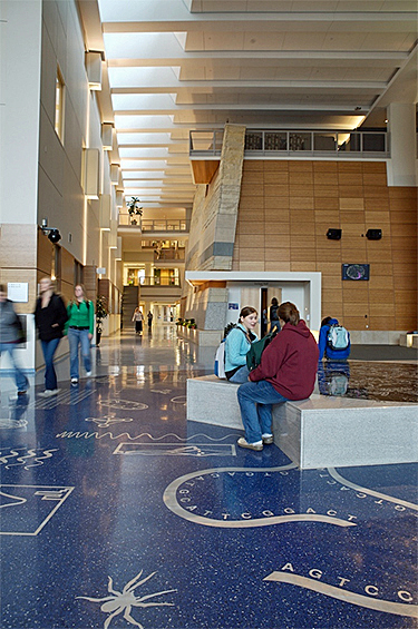
At Winona (Minn.) State University, the two-story atrium in the Science Laboratory Center incorporates a stairway as well as a bridge for movement from one side of the building to the other. Multiple materials and colors add visual interest, and the artwork doubles as a teaching and communication tool.
Main Street at Genencor is vibrant with various colors, forms and materials.
Incorporating functional elements, such as a stairwell, into an atrium or reception area provides opportunities for interaction among people who might not otherwise cross paths regularly. Ideally, such a prominent stairway would be a highly detailed and well-finished architectural feature that enhances the entire lobby.
A large atrium might feature lounge seating at balcony areas, providing alternative work areas for individuals or small groups. These areas may be informal, with comfortable seating, tack boards, display areas and power/voice/data ports to accommodate laptops and other devices.
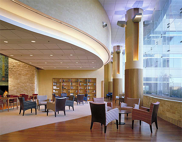
The Stowers Research Center provides a comfortable space to meet with guest and presents a first-class image of the campus.
Lighting in public spaces deserves special attention. In a spacious atrium, large-scale decorative fixtures define the scale of the space and make an important design statement. When planning lighting, remember that maintenance staff must easily access light fixtures. Also, consider the views from adjacent areas of the building, and even other buildings. Not doing so often results in bare lamps being visible from locations above the atrium. Beyond its impact on interior space, light serves as a nighttime lantern for the building exterior.
Conference Rooms
Conference rooms provide critical support space for a building. Whether formal (enclosed) or informal, conferencing areas provide building occupants with valuable communication and collaboration tools. These rooms should incorporate appropriate technology, sound controls to maintain privacy, multiple levels of lighting, flexible furniture for multiple configurations, and views to the building exterior to accommodate long meetings.
Formal and informal conferencing areas have equally important but unique functions. Enclosed conference rooms help focus attention, while informal meeting areas sprinkled throughout the building hint that the opportunity to collaborate is never far away.
Sound control for enclosed conference areas allow presenters and other participants to interact without fear of disrupting those in adjacent spaces. Various construction methods aid in sound control, the most straightforward being to extend walls to the underside of the slab and include sound batts. Increasing the size of studs and the number of gypsum wallboard layers also factors significantly in sound control, as do sound-absorbent soft materials such as floor carpeting, lay-in acoustical ceiling tiles and wall-mounted acoustic panels.
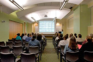
A successfully designed conference room also features varied light levels and task-specific lighting.
The technology provided in a conference room is critical. In times past, a ceiling-mounted projector and projection screen would have sufficed. Today, however, designers must consider a myriad of equipment, including LED projectors, projection screens, LED/plasma screens, teleconferencing systems, networked computers, whiteboards, tack boards, sound-masking, ceiling-mounted speakers, power/data connections to furniture, conference-call modules and preset lighting configurations. For complex conference rooms, carefully consider how all of these elements may work together.
A room may have general ambient lighting, wall-washers at the perimeter to light whiteboards and tack boards, dimming downlights for low-light presentations and specialty lighting for video conferencing. For multimedia presentations, lighting can be controlled by a single panel with function-specific settings, providing a user-friendly interface for a wide variety of presentation styles and needs.
Conference room furniture should accommodate the anticipated presentations. Attendees may be in an auditorium-like setting, a classroom setting, a conference table setting, in small teams or any number of scenarios. Folding tables and stacking chairs are convenient as they may be easily removed or reconfigured. In that case, provide ample storage space nearby.
Natural daylight provides welcome visual relief during long meetings. In spaces with exterior day lighting, light control must be designed into the space. With dual roller shades, one shade reduces direct daylight and glare, while a second shade, for presentations, blacks out all daylight. When blackout shades are used, the system must include side channels to prevent light from leaking in.
In larger conference rooms, consider food service, as long meetings typically include refreshments. The integration of a pass-through window with access on each side or a separate breakout area allows minimal disruption, which is ideal.
Lounges and Break Rooms
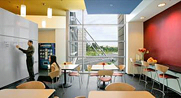
Lounges and break rooms are important common amenities. Planners must decide early on whether to have a lounge/break room on each floor or a single central amenity for the entire building. Consider the culture of the researchers and the design of the facility as a whole. Lounges/break rooms provide relief from work and are intended to act as anchors within individual floors. When positioned at key locations that allow for cross-traffic from multiple departments, they foster interaction.
Provisions should be made for local copying, printing, office supplies and mailboxes, along with amenities such as coffeemakers, microwaves and floor-standing water filters or dispensers. Food or beverage vending machines are provided in most facilities. Like break rooms, vending machines may be centralized or decentralized. Because machines add considerable heat to a smaller enclosed space, they should be properly ventilated.
Break-area design should include a convenient yet unobtrusive area for trash and recycling bins. Ideally the bins should be concealed, yet logically placed so their location and use is clear.
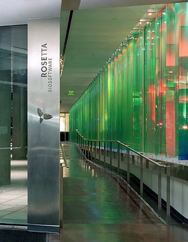
Merck Rosetta handicap ramp is colorfully designed with added educational information to make the walk enjoyable and memorable.
The engineering services are painted and exposed to provide the image desired by the client and to provide easy access for maintenance.
Corridors serve multiple functions, and thus command attention on many levels during planning. They define a facility's layout; serve as hallways with opportunities for displays and interaction; and house ducts, piping and wires for the mechanical, electrical and plumbing systems in ceilings. In the following paragraphs, we examine important elements of corridor ceiling systems, hallways, doors, windows, flooring, finishes, seating and displays, as well as office and service corridors.
Corridor Ceiling Systems
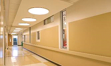
The research corridor is uniquely designed to feel welcoming. Interior glass provides views into the labs, and the ceilings, windows and floor patterns are thoughtfully coordinated.
Ceiling plane options have expanded beyond a lay-in or exposed ceiling. Choices now also include metal or wood panels (both available with perforated faces for acoustics) and any option combined with gypsum wallboard. Access should be easy so that routine maintenance does not disturb laboratory activities. To determine which type of ceiling system is appropriate, ask the following questions:
- What is the desired look of the corridor?
- What type of ceiling lighting is desired?
- What are the maintenance requirements of the ceiling?
- How often will the ceiling need to be accessed?
- Will there be significant height restrictions due to intensive ductwork?
Laboratory corridors are often quite long due to the modular layout of labs. Creating a ceiling system with some design complexity involving different types of materials will visually break down corridor lengths. Lighting can also de-emphasize the length. Varied lighting levels can assist in wayfinding by providing more light at major intersections or lab entrances and lower light where ambient light suffices. Corridor light selection can also influence which ceiling system to select. Light fixtures designed to bounce light off ceilings should be paired with a monolithic surface for even light distribution. To help an exposed ceiling choose fixtures that direct light away from the ceiling.
The amount of ceiling access required is determined in part by the layout of the HVAC ducts, piping and wiring. Some layouts have major access points above a main corridor, while others have access points above lab ceilings. If access points are above a main corridor, a flexible ceiling is best. The ceiling may still be composed of various materials, but the design should take into account how each material accommodates access.
Some ceiling systems allow for frequent access. Exposed structures are ideal for a heavily accessed HVAC system and when ceiling heights are limited. But it is difficult to control the installation of the ceiling elements for a tidy end product. If mechanical systems are exposed, acoustical liners should be used to minimize noise from air flowing through ductwork, and the pipes should be painted. With a sufficient number of air changes flowing through a space, little or no dust is likely to collect on the pipes.
More Than a Hallway
Corridors offer opportunities for people to see each other and exchange ideas. The most successful lab corridors have interior windows, provide places to sit, are well lit, include image-enhancing displays, and are finished in a variety of colors, patterns and materials.
Some corridors double as image-enhancing public tour routes, allowing guests to safely view labs without interrupting activities. Such routes are generally along the outside wall of the first floor, with views to some interior labs and the exterior campus, or at one end of the building on all floors. These routes often feature well-lit, educational displays about the organization or the type of research being conducted. In corridors that are less public, marker and tack boards can provide workers with another way to share information.
Door Details
Corridor doors should be a strong design element if a rhythm that integrate floor, wall and ceiling patterning is created during lab planning and schematic design. Lab doors, with a glazing inset where appropriate, should be recessed to prevent them from swinging into the path of a passerby, and the inevitable lab signage should be treated as a design element within the recess. Tack boards indicating location can serve as temporary or permanent signage.
The durability of lab doors is important because carts and equipment cause damage over time. One solution is to surface-apply stainless steel plates to the lower half of the door. Some newer door systems have an integral stainless steel-edge trim at the jamb as well as integrated, rather than applied, stainless steel plates on both sides of the bottom half of the door. Although they cost more, doors with the integral protection save money over time because those with applied protection are replaced more frequently.
Corner guards and guardrails are important in laboratory corridors because carts and equipment can damage wall edges and surfaces. Materials for corner guards and guardrails range from acrylic and plastic-molded to aluminum and stainless steel. The appropriate material is determined by the amount of abuse anticipated, the budget constraints and the design aesthetic.
When a guardrail does not protect a corridor, cementitious wallboard or high-impact wall panels may be applied to the wall from the base to 36-inches to 42–inches high. Manufactured in standard sheet sizes, these products are surface-applied and can be installed in a modular fashion to create an attractive design element. Another option is high impact-resistant gypsum wallboard, which can be installed in conjunction with standard (and less expensive) gypsum wallboard for a seamless installation.
Well-Placed Windows
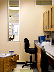
When possible, support labs should include windows looking into the large open labs and other adjacent spaces.
It is important that corridor windows allow natural daylight to flow deeply into the interior of the building. And no matter how windows are patterned along the corridor, they should correspond with circulation zones inside the labs. The heights and locations of windows should also coordinate with lab equipment. Lab benches with overhead shelving will conflict with lower windows. Thus, such shelving - whether it is placed initially or at a later date (which is often the case due to the flexibility of labs) - must be considered when placing interior windows. Clerestory windows are usually appropriate about 7 feet above equipment, as long as there are no overhead connections between the ceiling and the equipment.
Corridor Flooring and Finishes
Corridor flooring and finishes are typically the same in adjacent labs, but when they are different and there are variations in thicknesses of flooring between the corridors and labs, a transition is needed to minimize the impact of carts moving between the spaces. Almost any commercial wall finish may be used in corridors as long as repairs can easily be made, as walls are frequently damaged.
Corridor Seating and Displays
Seating areas, to accommodate conversation outside of labs, may be created adjacent to or at the end of a corridor. In most academic buildings, seating along the corridor provides a place for students to wait between classes. Thoughtful placement of pin-up strips/tack boards, whiteboards and display cabinets can add to the dynamic nature of corridors.
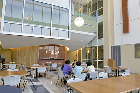
Comfortable spaces and seating outside the laboratory and office.
Office and Service Corridors
Like hallways, well-designed office corridors encourage communication, whereas interaction is lowered when departments do not share integrated space. Connectivity is important. Studies have shown that fewer than 5 percent of people will meaningfully communicate with each other once a week when their offices are more than 100 feet apart and segregated.
Service corridors typically house the lab engineering services. If the corridor is at least 10 feet wide, the opposing walls may store supplies, such as gas cylinders and even noisy equipment that otherwise might be in labs. Because service corridor equipment is noisy, generates heat and is unattractive, service corridors should not be near the main entry into the labs.
Elevator and Stairs
Elevators and stairs, along with main corridors, make up the public circulation system in a building, and as such, they should be highly visible and pleasant to use. Passenger elevators should be situated along main corridors for easy wayfinding. Most laboratory buildings need at least one passenger elevator (near the main entrance/reception area) and one freight elevator. It is a good idea to place an architectural stair near the passenger elevator in case it malfunctions and also to encourage the use of stairs. Many institutions now actually require that buildings have one set of centrally located fire stairs with upgraded materials to promote a healthier workforce through the use of the stairs. The freight elevator may either be adjacent to the passenger elevator(s) for cost and efficiency or, more typically, away from pedestrian traffic, such as near the loading dock. The latter can increase building security by tightly controlling building access. The freight elevator usually is controlled by a security access card and used only for transporting materials, supplies or equipment.
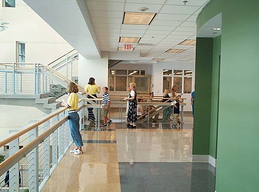
In the atrium of Florida Atlantic University's new research facility, the main stairs are near the elevator to encourage their use. The stairs also serve as a design feature and are highly visible to facilitate communication.
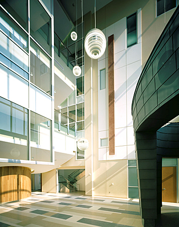
This fire stair, which doubles as an architectural stair, has a fire shutter on the first floor; glazing is on the remaining floors.
Fire stairs must be a set distance from each other, usually less than 300 feet if the building is fully equipped with sprinklers. The stairs should be highly visible for wayfinding and security, and should be located along the outside wall to allow for exterior windows and views. The lantern effect that the exterior glass creates makes for a safer building, especially at night, because people can see one another. Fire stairs should be wider than the minimum standards required by the building codes, allowing two people to comfortably use the stairs at the same time.
A utilitarian fire stair is often transformed into a stunning design feature through the use of wood, metal and tile upgrades; a window seat; natural daylight; and views to the exterior. If the stair also includes interior windows, which require fire shutters, it will be visible and inviting from the main corridor as well. Although fire shutters, which automatically drop from the ceiling to cover the window glass in case of fire, are an additional expense, they allow a fire stair to become a highly successful design element.
The flooring on a well-trodden stairwell must be extremely durable. A modest upgrade to a utilitarian stair may include rubber or treated concrete at the treads and/or risers. For better durability, and if a soft surface is desired, carpet is typical. Although a wool carpet is a significantly higher first expense than nylon carpet, it holds up better and lasts longer. Hard monolithic finishes, such as terrazzo and stone slabs, are ideal as they require very little maintenance over a long life span. Stair railings protect the wall, so wall finish durability is not a great concern. An upgraded stair often features special light fixtures, but they must be selected carefully to avoid a direct view of the lamp from above or below.
Research Labs
The quality and image of the research lab are of utmost importance to the end users. Key considerations are use of materials, type of casework, color scheme, natural lighting, interior glazing, light fixtures, equipment space and efficiency.
Casework must accommodate the specific needs of the current research team yet provide flexibility for future use. Determining the initial amount of casework, and the fixed-to-mobile ratio, is important. Some casework should allow for vertical adjustment. To ensure that money is well spent, the researchers should be given an opportunity to review the layout and specific design of each type of casework. As discussed in Chapter 6, mobile casework is popular in many labs today, reducing the need for fixed casework. A practical layout places modular casework in the center of the lab and fixed casework at the perimeter, allowing for maximum flexibility at the center while reserving the outside for utilities, which are unlikely to change.
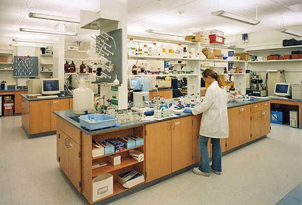
The choice of casework (metal, wood or plastic) and the color of casework finishes have a significant impact on the quality of the design.
Color, both in floor patterns and along the wall, is an inexpensive design element that can dramatically impact the visual image of each lab as well as the entire building. Floor patterning should take into account three zones: casework, circulation and equipment. The patterning should be modular, working off the lab bench modules. Ideally, the pattern should help define these zones while being visually flexible enough to look appealing in future lab reconfigurations. And, because any clear wall space without windows may eventually be covered with equipment, flexibility is needed in wall patterning as well.
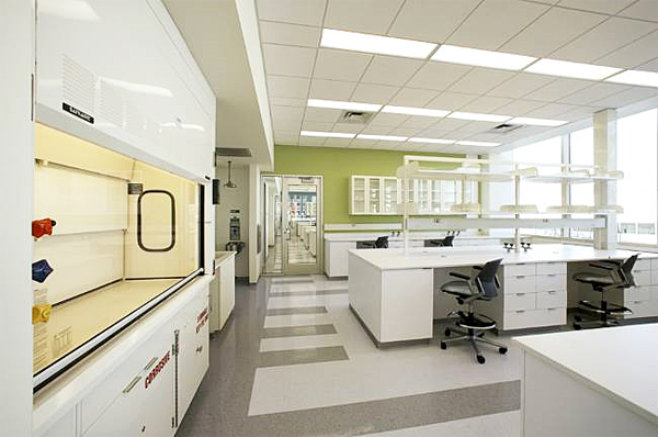
Lab colors and patterns should complement the design and finish of the building as a whole. Beyond simply being a matter of taste, color may affect how a person perceives his or her work.
All colors reflect onto the surrounding area, especially bright or highly intense colors. If an environment requires sensitivity to light or color accuracy, a neutral pallet may be best. Furthermore, high-contrast colors may cause eyestrain. Working with light material on a dark surface, for example, requires a person's eyes to constantly adjust, causing the eyes to tire over long periods of intensive work.
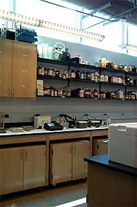
At Florida Atlantic University, the exterior windows are 7 feet above the floor, allowing storage along that wall.
Space for equipment should be coordinated with the placement of casework and with the design of the lab as a whole. Placing equipment along one wall or in separate rooms allows labs to be more open. And remember to place tall equipment with care as it may block views. It is critical to create efficient bench space, casework and storage space in each lab. The key purpose of lab modules is efficiency; they create optimum space for research and circulation. State-of-the-art labs take advantage of the volume of space. Shelving and cabinets above benches must be fully coordinated to maximize storage space. In locating storage high above benches, take sprinkler requirements into account. Also, be aware that, in lieu of windows, many researchers would rather have additional wall space for equipment and storage to use the full volume of space in their labs.
The color and finish of casework, as well as the choice of material (metal, wood, plastic, or a combination of wood and metal), is an important part of the visual setting. The casework and countertop should complement the walls, floor and ceiling. Chemical-resistant tops and stainless steel counters can present crisp images that are visually pleasing.
The integration of functional yet attractive lab accessories, such as tack boards and whiteboards, can support teamwork. As individual research methodology gives way to the research team approach, design elements that support collaboration within the lab environment become more important.
Whenever possible, allowing natural daylight into the labs improves the image and quality of each space. If there are panoramic views to the exterior, designers should take full advantage of them by locating appropriate labs and offices along the outside walls. The use of sloping lay-in ceilings may dramatically increase the distribution of natural daylight and the quality of the work environment. Interior windows allow people to see each other, and the light filtered through the building creates a more pleasant work environment. The design and location of light fixtures may add to the overall quality of the space so long as glare is controlled, the brightness-contrast ratios are high and color rendition is accurate.
As with corridors, most labs have either a lay-in or exposed ceiling system. A challenge arises when trying to allow for flexibility for future reconfigurations while integrating into the ceiling system services such as lighting, overhead service carriers and chilled water beams. A lab built on a series of modules such as a column grid, casework-to-circulation/equipment or an overhead services system should have the ceiling systems based on the same modules. Where the ceiling modules occur in a lay-in ceiling, a change in the ceiling material may be helpful in accommodating future reconfiguration with minimum impact on the overall ceiling system.
Acoustical problems, mostly due to loud mechanical supply and exhaust ducts or equipment, are fairly common in labs. Hard surfaces in the room also bounce noise around. Noisy ductwork is usually the result of too much air being moved through the ducts or the lack of sound attenuators. If the equipment is loud, consider locating it in a separate room.
Researchers spend about half of their time in the lab and half in their offices, which can become cluttered quickly. Designing a visually successful office involves addressing several elements, including the quality and quantity of furniture; comfortable meeting space, the number of windows; the amount of shelving and other storage space; and functional requirements, such as computer work.
Private offices should have inboard orientation allow for an egalitarian distribution of the daylight and views to the exterior. By locating offices away from the window wall, generally ringing the core of the building, the heating and cooling of the overall space is more consistent. Furthermore, orienting a circulation path along the window wall encourages teaming by providing informal meeting spaces at the window.
Open office environments (cubicles) should be based on a module so they can be reconfigured easily. The lighting should be direct/indirect to reduce eyestrain and glare at computer monitors. A critical yet often overlooked element of open offices is general storage and filing space. This is a fundamental part of the programming process; if it is disregarded, the difficult choice of storage versus workspace will have to be addressed later in the project.
Interior Finishes
Floor finishes for labs are based on lab functions. To find the most appropriate, compare them for durability, chemical resistance, cost, maintenance, and aesthetics. In extremely clean or wet areas, troweled flooring is used because it does not contain adhesives, which can fail due to moisture. If bacterial growth must be prevented, use flooring that can be heat-welded into a seamless application with a cove base. Less stringent requirements allow for seamed tile flooring.
Tiles, which come in many shapes and sizes, offer the widest opportunity for design, color and patterning. As with modular planning for lab casework, tile flooring design should involve standard material sizes. Patterning should be a fractional derivative of the whole tile unit to reduce waste and labor costs. Some tiles can be heat-welded, making them an appropriate design solution when seamless flooring is required.
Maintenance may be a key factor in flooring selection. In labs where sensitive equipment is calibrated to detect particulates in the air, flooring suited to damp mopping is preferable to flooring suited to stripping and waxing. These cleaning processes create air-quality disturbances, which may cause erroneous equipment readings.
Static electricity can also affect some equipment. Some flooring materials can be grounded through their adhesive and the material itself to minimize the effects of static electricity.
Heavy equipment, especially when mobile, can wear on flooring. Materials with a higher pounds-per-square-inch rating stand up better to the long-term weight of equipment. Specific adhesives are available for some flooring to lessen the effect of rolling items and to increase the PSI.
Rapidly renewable and sustainable materials such as cork, linoleum and bamboo are now widely available and should act as a starting point for the investigation and creative application of environmentally friendly materials. Using materials such as recycled glass as an aggregate in terrazzo offers not only a unique aesthetic, but also helps create a greater demand for recycled and sustainable building materials. Wherever appropriate, sustainable materials should be considered for projects as part of a larger concentrated effort on sustainable design.
The following are advantages and disadvantages of various flooring types:
Concrete: Concrete is a very durable, relatively inexpensive floor finish and reasonably easy to clean. Disadvantages include poor chemical resistance; vulnerability to harsh chemicals; lack of comfort for standing and walking due to lack of resilience; and inconsistency in appearance over large areas. Concrete can be sealed, stained or tinted, depending on the desired aesthetic. Stained concrete is slightly more expensive than sealed concrete. Exposed concrete, whether it is sealed, stained or tinted, also costs more because the quality finish requires a higher quality concrete. Using vinyl composition tile (VCT) as a cost baseline, basic finished stained concrete will tend to be slightly less expensive than VCT.
Resilient tile (vinyl composition tile): Vinyl composition tile is cost-effective, durable, reasonably easy to clean, easy to replace, offers a wide range of colors and patterns, and is somewhat comfortable to walk on. Its disadvantages include the following: it has only fair resistance to chemicals, it has many joints where bacteria can collect, it has a low PSI, it has the highest life-cycle maintenance cost of all materials compared, and it is not an environmentally sensitive solution.
Resilient sheet vinyl: This flooring is durable, easy to clean, comfortable to walk on, may be turned up for a seamless cove base, and it prevents bacterial growth when heat-welded. Its chemical resistance is good and there are fewer joints than with tile flooring. Its chief disadvantages are high material cost (2.5 times that of resilient tile), high labor cost for extensive patterning, a low PSI and it is difficult to repair.
Solid vinyl tile: Solid vinyl tile is probably the most flexible flooring option. In addition to a wide range of colors, sizes and patterns available, it can be grounded, has a high PSI, has good chemical resistance, can be heat-welded with a cove base and only needs a damp mop for cleaning. The main disadvantages are that vinyl is not an environmentally sustainable material and the cost is approximately 2.5 times higher than the baseline cost of VCT.
Rubber: The advantages and disadvantages of rubber are similar to solid vinyl tile. A key difference is that, in addition to being available in tiles, it is also sold as a rolled product, which minimizes seams. Some rubber products can withstand the harsh usage usually reserved for troweled flooring.
Linoleum: Linoleum, available in sheets or tiles, is one of the best design options available. An all-natural product, it is respectful of the environment, requires little maintenance, is easily cleaned and repaired, and is time-tested in European installations. Where it excels in design options, however, it falls short in chemical resistance. With a moderate PSI and sensitivity to heavy moisture, linoleum should be reserved for applications similar to that of VCT. It is similar in cost to sheet vinyl, but the life-cycle costs are much lower because it does not require stripping and waxing.
Troweled epoxy: Troweled epoxy provides excellent resistance against chemicals and it is durable and easy to clean. Disadvantages include cost (more than four times the cost of resilient tile and 2.5 times more than sheet vinyl), limited color options, and difficulty of repair.
Carpet: Carpeting is an excellent floor finish for offices, large lecture halls, and common areas, but it is inappropriate for wet laboratories because of chemical spills and potential bacterial growth. Carpet tiles are a preferable to broadloom in areas where long-term or heavy use will require frequent carpet replacement. Carpet tiles also can create less waste, are widely available with recycled content, and may be recycled.
Ceilings either have a lay-in tile system or are open to the structure and mechanical systems. Ceiling tiles must be suited to the lab function. In open labs with a lay-in ceiling, the type of ceiling tile is not restricted. Where a cleaner environment is needed, cleanroom tiles with a scrubbable face may be required. In BSL-4 labs, a gypsum wallboard ceiling with an epoxy finish is recommended for areas that are frequently wet.
Ceiling tiles come is a variety of sizes. Of the most common sizes, 2' x 2' is generally preferred over 2' x 4' because the smaller size resists sagging and provides a smaller ceiling element.
Many labs work on a 10'8" module that is reflective of both a structural and working lab bench module. This allows for maximum flexibility in future reconfigurations. The ceiling utilities correspond to the 10'8" module; as a result, every 10 feet there are 8 inches of another material to accommodate utilities. In traditional lab design, the 8-inch-span was made of gypsum wallboard. However with a wide variety of metal ceiling tiles and panels now available, metal tiles are preferred. As changes occur, the tiles can easily be replaced, whereas gypsum wallboard must be patched, mudded, sanded and painted. Also the metal tiles can sit in the same type of ceiling grid as the other ceiling tiles, thus creating a more uniform appearance and avoiding the fussy transitions that often accompany a gypsum wallboard solution. Metal tiles are widely available in custom widths and lengths, some up to 10 feet. The longer length prevents small pieces from being cut and appears monolithic while still using a standard ceiling grid.
Lab walls are typically constructed of gypsum wallboard and are usually painted. In BSL-2 and sometimes BSL-3 labs, the paint is generally an eggshell finish. Clean areas in BLS-3 and BSL-4 labs require an epoxy finish.
For ease of maintenance, finishes for lab floors and walls are typically hard, and little can be done to mitigate noise. Insulation in walls and above the ceiling will reduce noise transmitted from one room to another. Acoustical design options for ceilings are limited because ceiling surfaces must be fully cleanable. A ceiling can be constructed of acoustical tile or perforated acoustical metal tile. If there is no lay-in ceiling and the piping and structure are exposed, acoustical baffles can be added. However, two significant problems with acoustical baffles—additional cost and a surface that can be easily contaminated—may make an exposed ceiling less desirable.
Although critical to safety, smart wayfinding also serves to create a lively, interactive research community. Far beyond signage, successful wayfinding depends on the information inherent in a building's design.
Wayfinding begins with a welcoming entrance. It should help define a building's function and orient people quickly. An atrium, or volume space, near the entry is especially beneficial for an academic research facility as well as for many private and federal institutions.
Amenities such as conference/meeting rooms, restrooms, stairs and elevators activate such volume spaces, as do mailrooms, lounges and eating establishments. Visually engaging labs overlooking the atrium can create added interest. Virtual screens that allow people to see what is happening throughout the building are also becoming popular.
The main circulation is the next key wayfinding issue to consider. A single-corridor design operates like Main Street, with everyone coming and going along the same path. A double corridor provides more direct access to laboratory spaces and offices, but tends to separate people and can be confusing. Examples of both concepts follow:
At JABSOM Phase II in Honolulu, Hawaii, a single corridor clearly leads to all program spaces to the north or south. The corridor widens to the west with informal seating, a view and an egress to the exterior. The east corridor is secure, and lab entry alcoves are recessed for safety and to provide space for equipment to swing through the doors from the corridor. An exterior view in the east corridor provides orientation and helps define an egress to the exterior space and an adjacent building.
The upper floor of Genencor International Technology Center in Palo Alto, Calif., features a very small corridor off the elevator with office suites to the east and west and open labs to the north and south.
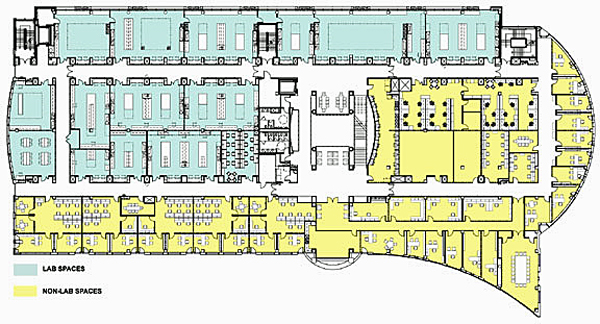
A "racetrack" corridor is best suited for extra-deep spaces with program space in the middle. The double-corridor setup, however, can split the population and impede wayfinding. Here, a central atrium surrounded by common amenities and exterior views at the end of the corridor support good wayfinding.
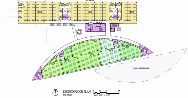
NASA's Cape Canaveral, Fla., research building organizes all wayfinding around a clear entry from the west leading into an atrium overlooked by circulation areas on the upper floors. On each corridor, one wall is along the exterior for natural light and excellent views; the other wall provides access into the labs. The end of each corridor leads to fire stairs open to the exterior.
Federal Agencies
- Department of Energy (DOE), Office of Science —For examples of facilities to support instruments of science, see DOE's Brookhaven National Laboratory
- Department of Energy (DOE), Environment, Health, Safety & Security
- Department of Veterans Affairs (VA), Office of Construction & Facilities Management (CFM) — VA Research Laboratory Design Guide
- Environmental Protection Agency (EPA), Office of Administration and Resources Management (OARM)
- General Services Administration (GSA), Office of Chief Architect (OCA)
- National Aeronautics and Space Administration (NASA), Facilities and Real Estate Division (FRED)
- National Institutes of Health (NIH)— Office of Research Facilities Development and Operations (ORF) developed the NIH Design Policy and Guidelines to provide standards to assist planners, architects, and engineers in designing biomedical and animal research facilities for the NIH.
Organizations/Associations
- A Design Guide for Energy-Efficient Research Laboratories —A reference that helps facility owners, managers, and designers apply energy-efficiency features in laboratories.
- Environmental Performance Criteria (EPC) —The Labs21 Environmental Performance Criteria is a rating system specifically designed for laboratory facilities. It builds on the U.S. Green Building Council's LEED® Green Building Rating System .
- Labs21 Design Process Manual —Includes a "quick reference" sustainable strategies checklist as well as links to key resources for each stage of the design process.
- Labs21 Tool Kit
- Labs21 Annual Conference presentations
- U.S. Green Building Council , LEED® Application Guide for Laboratory Facilities (LEED-AGL)—Because research facilities present a unique challenge for energy efficiency and sustainable design, the USGBC formed the LEED-AGL Committee to develop a guide that helps project teams apply LEED credits in the design and construction of laboratory facilities.
Publications
- ASHRAE 110 Method of Testing Performance of Laboratory Fume Hoods
- ASHRAE Handbook - HVAC Applications , Chapter 16 Laboratories
- ASHRAE Laboratory Design Guide
- Biosafety in Microbiological and Biomedical Laboratories , 5th Edition by U.S. Department of Health and Human Services, Centers for Disease Control and Prevention and National Institutes of Health. Washington, DC: U.S. Government Printing Office, May 2009.
- Building Type Basics for Research Laboratories , 2nd Edition by Daniel Watch. New York: John Wiley & Sons, Inc., 2002. ISBN: 978-0-471-21757-2.
- Guidelines for Planning and Design of Biomedical Research Laboratory Facilities by The American Institute of Architects, Center for Advanced Technology Facilities Design. Washington, D.C.: The American Institute of Architects, 1999.
- R&D Magazine —Provides information on a variety of topics related to laboratories. The R&D Lab of the Year award is presented annually to outstanding laboratory facilities throughout the United States.
WBDG Participating Agencies

National Institute of Building Sciences Innovative Solutions for the Built Environment 1090 Vermont Avenue, NW, Suite 700 | Washington, DC 20005-4950 | (202) 289-7800 © 2024 National Institute of Building Sciences. All rights reserved. Disclaimer
Language selection
- Français fr
Canadian High Arctic Research Station (CHARS) floor plans
Floor plans, ground floor plan of the main research building, second floor plan of the main research building, ground floor plan of the field and maintenance building, second floor of the field and maintenance building.
A full description of the key rooms of the Canadian High Arctic Research Station floor plans.

Site plan of the Canadian High Arctic Research Station

The main entrance to the station will be at the top right of the station and will lead to twenty-six public parking spaces. The pedestrian marshalling yard, and field and maintenance building will be located to the left of the parking spaces. The pedestrian marshalling yard will serve as additional space for field workers, researchers and others to prepare to go into the field. This can include setting up tents, packing and double checking field supplies.
Above the field and maintenance building there will be two entrances: the garage entrance and the maintenance staff entrance. To the left of the field and maintenance building, there will be field storage and space for future development. Science and technology equipment, vehicles and dry goods will be stored in field storage.
Below the space for future development there will be two housing triplexes. Each triplex will have three units and four bedrooms within each unit, along with common spaces that offer access to wireless internet. There are eight parking spaces allocated for the triplexes, along with housing storage to the left of the triplexes.
To the right of the triplexes will be the main research building. The research building will have two public access entrances at the bottom left of the building and the top right of the building. There will also be a field entrance, bicycle rack and field loading dock at the top left of the building. There will be twelve snowmobile and all-terrain vehicle parking spaces at the bottom right of the main research building. Directly above the main research building there will be the marshalling yard, which is also located below the pedestrian marshalling yard and the field and maintenance building. The marshalling yard will be a large open space, which allows scientists to wash and dry field equipment, and sort and pack field materials.
To the right of the marshalling yard there will be a public outdoor space, the qaggiq, and eleven preferred parking spaces. The qaggiq will be an outdoor space styled as a communal igloo, which will welcome staff and guests to the station. Community activities can also be conducted here.
Surrounding the site are various sensitive organisms that have adapted to specific environmental conditions (e.g. cotton grass, dwarf shrub, etc.).

The ground floor plan for the main research building is long and linear. A large public access zone wraps around the dedicated science and technology spaces. Facing the Cambridge Bay hamlet, the public access zones will take advantage of the southern exposure to bring in light. The public access zones will foster interaction, conversations, and the exchange and sharing of information.
The ground floor includes laboratories, workshops and offices, as well as support functions such as a kitchen, storage and loading docks. Many of the laboratories will include windows into the corridors to allow visitors to watch the scientists at work.
Main public access will be at top right of the building, leading to the display area, a knowledge sharing centre and a large multi-use space. Another public access entrance will be located at the bottom of the building and will lead to a business incubation space and offices. Office space will be located at the bottom left, and the workshops and laboratories will be located above the office space and directly to the left of the public access area. There will be a field entrance and a field loading dock at the top left of the building.

The second floor includes analytical laboratories, offices and the extensive mechanical space required for the facility.
Meeting rooms and offices will be located at the bottom of the building. Above the meeting rooms will be a general analytical lab and computer geographic information system room. The right part of the building will be open space. To the left of the open space there will be equipment storage, a growth chamber, genomics lab and a multi-use lab. To the left of the growth chamber and general analytical lab there will be an electrical room, fan rooms and various mechanical rooms. There will also be a laundry room in the top left of the building.

The field and maintenance building is a highly functional building that will support field activities and the main research building. Within the building there will be areas for rough processing of field material, for preparation for field work, for storage, and for maintenance and operations.
There are multiple entrances to the field and maintenance building: a main public entrance, a marshalling entrance and a storage garage door at the bottom of the building. There is a boiler room entrance at the far right, and a maintenance garage entrance, field maintenance garage door and maintenance staff entrance at the top left of the building.
The right portion of the building is allocated to the boiler room, generator room, main electrical room and telecom room. To the left of this section is a diving facility, rock processing room and storage. Directly left of the storage room there is a rough overflow room. Above the rough overflow are stairs, a compost room, hazard waste room and a wood workshop. To the left of the wood workshop there is a maintenance garage. Below the maintenance garage there is equipment storage and the marshalling staging area. To the right of equipment storage, maintenance garage and marshalling staging area is the marshalling closed office and more equipment storage.

The second floor of the field and maintenance building includes logistic and maintenance offices, a telecom room, a janitorial closest, washrooms, a kitchenette and a mechanical room.
The mechanical room is located at the top of the building. Directly below it are the kitchenette, bathrooms, and a janitorial closet. The logistics and maintenance offices are located below the janitorial closet. Above the office space there is also a telecom room.
Page details
- Other Building Types
Lab, research facility design
Learn tips on how to design labs and research facilities — some of the most high-tech buildings around.
Respondents
Kelley Cramm, PE, LEED AP BD+C
Associate/Mechanical Technical Leader
Henderson Engineers
Kansas City
Bryan Floth, LEED AP, AIA
Senior Project Manager
Burns & McDonnell
Kansas City, Mo.
George Isherwood, PE
Vice President, Health Care/Laboratory Group Leader
Peter Basso Associates Inc.
Troy, Mich.
Adam Judge, PE
Associate/Mechanical Project Engineer
TLC Engineering Solutions
Tampa, Fla.
Iain Siery, PE
Senior Mechanical Engineer
Philadelphia
David Wilson, PE, LEED AP
Senior Engineer
Raleigh, N.C.
Kelley Cramm
Cramm is an associate and mechanical technical leader at Henderson Engineers. She received a 2019 ASHRAE Exceptional Service Award and has more than 30 years of industry experience.
Bryan Floth
Floth leads architecture and integrated design-build projects across the U.S. for the company. With nearly 30 years of experience, he has partnered with clients throughout his career to design and implement complex higher education, commercial, industrial, institutional and mission critical facilities.
George Isherwood
Over his 35-year career, Isherwood has worked on numerous new-construction and renovation projects. His health care work includes patient towers, ambulatory care facilities, operating rooms, cardiac catheterization labs and more.
As Associate/Mechanical Engineer, Judge works on a broad range of project types. He has a wealth of laboratory experience, including recent renovations at the University of South Florida College of Medicine.
Siery brings 14 years of progressive experience to the science and technology sector to CRB. His areas of specialty include mechanical utilities, HVAC, industrial ventilation and plumbing design for critical environments in R&D and manufacturing.
David Wilson
As senior engineer with Dewberry, Wilson centers his work on mechanical, electrical and plumbing projects. He brings more than three decades of engineering experience to the firm.
CSE: What’s the biggest trend in laboratory and research facility projects?
Kelley Cramm: Probably the biggest trend we’re seeing is an increased move toward open, modular laboratories. Open, modular labs accommodate changing research over time and allow flexibility for new equipment, researchers and evolving technology. They also improve collaboration between researchers from multiple disciplines.
To improve flexibility, many labs are using pre-wired and piped modular casework with “plug and play” capability. The utilities are supplied to a ceiling panel or overhead service carrier and connected to the casework from there. Utilities can be distributed to every module with services not initially needed valved and capped above the ceiling or in the overhead service carrier. This allows flexibility for changing needs with minimal disruption.
Bryan Floth: The biggest trend we’re seeing within laboratory and research facility projects is designing for flexibility. Advances in scientific research are accelerating in all areas. This has created unprecedented demand for new and more sophisticated facilities that can accommodate state-of-the-art technology. The cost to remodel facilities at the same rate can be substantial. It’s forcing a lot of planning and designing to be more generic and flexible, to better react to shifts in the industry.
George Isherwood: The biggest trend we are seeing is working through the balance of energy efficiency with equipment costs for the energy performance. Most, if not all, of our clients have “green” plans until they realize the increase in equipment costs.
Adam Judge: Most new facilities we have seen in the past few years have included large, shared open lab areas that catalyze collaboration and conversations among researchers. This collaboration encouraging concept is even spreading outside the laboratory spaces and into the common area and circulation spaces, such as open stairways and atria creating visibility between different floors, areas or departments. Often the primary investigators are not all known at the time of design, so most laboratory spaces need to be designed to be flexible for adaptation to future needs.
Iain Siery: Generally, I think advanced therapeutic medicinal products research and development are on the rise. This is particularly true in Philadelphia, where several key advancements have been made that are driving significant attention to this space within life sciences. These projects have different drivers and require specific expertise to create facilities that support clients in this field.
David Wilson: Providing flexibility in the design of laboratory spaces and utilities to allow for modifications to the laboratory spaces on an individual basis as research changes or changes in researchers occur. The advancement in technology and funding availability is often driving changes in the type of research being performed at any given time and changes appear to be occurring more rapidly than in the past.
CSE: What future trends should engineers expect for such projects?
Isherwood: Integration of the controls throughout the projects are starting to gain momentum in the industry. We are starting to see multiple trades starting to work together to accomplish a more efficient system. Window shade controls are interfacing with lights that are interfacing with temperature controls. There have been several challenges with integrating these systems and allowing them to not only read into their system but adjust setpoints as well.
Siery: I am expecting continued and increasing pressure on projects due to overall cost. Today, we explore numerous approaches to managing the cost of projects. This includes saving time by integrating the design and construction process, as well as design approaches that directly manage cost such a target value design/delivery. Finding the right balance of flexibility, speed of delivery and cost has been increasingly central to the success of research laboratory projects. These aspects can be at odds in many cases. In particular within the life sciences R&D industry, speed to market is becoming more critical, so solutions to these challenges must continue to evolve.
Floth: Speed to market is critical for lab and research facility projects today and will continue to be critical in the future. There is a growing expectation for buildings to be designed and built faster. Schedule, productivity and innovation are always top of mind. Any scenario in which the research associated with a lot of these facilities is delayed can delay the ability of the research organization to meet market deadlines.
We’re incorporating lean principles and management approaches into the process to help meet expectations, delivering a high-quality, on-schedule project. The purpose of the lean management approach has two central components: a fully integrated team approach to design and delivery from the early stages of a project, and the incorporation of lean principles, processes and tools to attack the sources of waste. Together these two concepts can translate to big advantages for an owner.
While more traditional delivery methods often focus on the “what” of a project, lean management principles approach project design and delivery differently, placing greater emphasis on “how” a project will be designed, constructed and ultimately delivered for the owner.
Cramm: I think an increased demand for sustainability and reduced carbon footprint will be the overarching trend. Laboratories consume massive amounts of energy and water. This will drive changes to the way we design labs and to the way users operate in the lab. We will see an increase in the use of energy recovery, high-performance fume hoods, occupancy-based setbacks for lighting and ventilation, wind responsive exhaust fan modulation and improved ventilation effectiveness at lower air change rates. Users will be pushed to use more efficient lab equipment — especially freezers — and to shut down lab equipment when not in use.
Judge: I expect future projects to continue the trend of flexibility. This may mean flexibility to adapt the design to different floor plan layouts, different equipment or other environmental requirements as researchers are recruited during the design phase, during the construction phase or post-occupancy.
CSE: What types of challenges do you encounter for these types of projects that you might not face on other types of structures?
Cramm: Density of power is one key difference. We’re seeing an increased use of ultralow-temperature freezers and analytical instruments that come with computers and printers attached. This equipment demands more power than most other occupancies. Spare circuits to accommodate future growth and new instruments are critical. Another key difference is the hazards associated with laboratories and the resulting need for containment to protect personnel. This drives us to fully exhausted laboratories with systems that need to run 24/7. Another difference is the increased use of gases that create a flammability or asphyxiant hazard. These require specialized systems to mitigate the risk to human life and health.
Wilson: The challenge is designing utility and utility systems to be generic in nature but customized on a lab-by-lab basis to meet the current research needs of each individual space. Providing utility systems for future use in each laboratory may add additional upfront cost when initially constructing the building but allows for modifications to each laboratory on an individual basis without affecting adjacent spaces and associated research occurring in each space. Long-term research can be lost if disruptions to utility systems occurs due to shutdowns required to modify utility systems.
Floth: The biggest challenge is the complexity of these projects. Science facilities require design that integrates specialty building systems, utilities and equipment with the human element of a pleasant working environment. Each laboratory, clean room or research space has unique environmental requirements, but all have a focus on efficiency, flexibility and safety at their core. Layered on top of that, many facilities hope to attract grants and achieve other unique certifications, requiring additional guidelines beyond making the building code compliant.
Judge: Building in sufficient flexibility for changes in laboratory spaces can be much more challenging than in other types of buildings. Because laboratory equipment can often vary widely in utility requirements, much more flexibility must be built in. In addition, with the governing energy efficiency codes become more stringent, laboratory facility design often requires thinking out of the box to not only meet energy code requirements, but often beat them to meet the sustainability goals of the project.
Isherwood: Most buildings are built with the intent of keeping the occupants comfortable. People working in offices and students in classrooms are more productive when comfortable. Laboratories introduce harmful elements into that environment that can affect both the safety of occupants and the surrounding areas. The management of chemicals or other harmful elements is what makes laboratories unique.
Siery: Specific design challenges include creating inspirational environments that balance scalable infrastructure, flexible casework and utility distribution, constructability and project cost and schedule drivers.
CSE: What are engineers doing to ensure such projects meet challenges associated with emerging technologies?
Cramm: Innovation and creativity are key to successful laboratory design. The understanding that what’s happening in the lab today will not be what’s happening in the future is critical. Engineers should never design a “purpose built” laboratory. All systems and utilities need to be designed to be flexible enough to adapt to future changes in laboratory equipment and evolving research. This means planning for systems to be expandable and designing services using a modular planning approach. It also means sizing ducts and chases to allow for additional airflow and providing plenty of spare electrical circuits in panelboards to accommodate the inevitable addition of laboratory equipment.
Floth: Having an integrated team is a game changer when it comes to delivering facilities that meet challenges associated with rapidly evolving technologies. Long before design begins, our architects, engineers, planners, environmental specialists and construction professionals work with clients to establish requirements. This gets all stakeholders and involved parties on the same page from day one. By interviewing lab stakeholders — from director to technicians — our designers help shape facilities’ physical and aesthetic goals and objectives. We carefully analyze traffic flow, space needs, type and number of analyses, standard testing methods, lab safety and equipment and regulatory requirements — a crucial first step in turning the vision of a facility into steel, concrete and glass, utilities and systems.
Judge: Engineers need to get as good of an understanding as possible of potential future plans for the laboratory spaces. Considerations must be taken regarding ventilation, cooling and exhaust, power requirements — including emergency generator or uninterruptible power supply standby power — water requirements, data requirements and chemical quantity limitations of potential future equipment and processes. The design team must inform the owner of the assumptions and limitations they must live with.
Siery: I am seeing significant emphasis on integrated solutions that bring the design and construction experts together (design-build and design-assist) to improve overall project schedule. Then these teams can more effectively leverage budget management strategies such as target value delivery to ensure the project is successful.
CSE: Tell us about a recent project you’ve worked on that’s innovative, large-scale or otherwise noteworthy. Please tell us about the location, systems your team engineered, key players, interesting challenges or solutions and other significant details.
Floth: One recent project our team was selected for is the NextGen Precision Health Institute at the University of Missouri . We’re providing architectural, master planning and engineering design services for the $220.8 million research facility. The facility will aim to bring together industry partners; engineering, medicine and veterinary science students; and the federal government to pursue a collaborative approach to personalized health care, supported by advanced technology. Construction for the 275,000-square-foot facility is expected to be completed in October 2021.
Judge: Construction is nearing completion of the new 395,000-square-foot, 13-story University of South Florida Morsani College of Medicine and Heart Institute in the newly designated Water Street district in downtown Tampa, Fla. TLC Engineering Solutions teamed with architects HOK and builder Skanska for this design-build project with an estimated construction cost of $173 million. The project includes four classroom floors, including a 400-seat auditorium; three research laboratory floors; two shelled floors for future laboratory space; three shelled floors for future classroom, office or clinical space; and approximately 6,200 square feet of ground floor space shelled for future tenants. To promote interactions and collaboration, there is a five-story atrium with staircase connections for all floors of the College of Medicine and a three-story atrium connecting the three College of Medicine laboratory floors. The laboratory floors feature large open wet bench spaces, lined with smaller support labs.
The project includes run-around hydronic heat recovery loops to transfer heat from incoming outside air to exhaust airstreams and reduce cooling demand, purchased from a district chilled water plant. High-efficiency, low-flow fume hoods with automatic sash closers were specified to reduce outside air requirements. High-efficiency, natural gas fired condensing boilers are used to provide heating hot water and plate and frame heat exchanger skids are used to heat domestic hot water using heating hot water as a heat source.
CSE: How are engineers designing these kinds of projects to keep costs down while offering appealing features, complying with relevant codes and meeting client needs?
Cramm: Mechanical, electrical, plumbing and fire protection systems typically constitute 40% to 55% of laboratory construction costs. Involving engineers at programming can help reduce costs. Early input from mechanical, electrical and plumbing engineers helps to ensure optimum system design and integrates the MEP systems with the lab layouts. This results in more efficient MEP layouts that can reduce first costs. For example, with early input from the engineers, the MEP equipment and chases can be located optimally so duct runs can be shorter, pressure drop lower and floor to floor heights lower.
Judge: The key is determining which energy savings measures bring value to the project. This can mean an acceptable payback period to the owner or sometimes even lower first cost. Often there can be upfront savings by economizing on combining different building systems in different ways. For example, laboratory buildings typically require a significant quantity of water heating — for hydronic HVAC reheat systems, for domestic hot water at sinks and sterilization processes. By using a plate and frame heat exchanger to isolate heating hot water from domestic hot water, the HVAC boilers can be slightly upsized and the domestic water heaters can be completely eliminated. This cuts down on equipment costs, piping costs and recurring maintenance costs.
Floth: Costs can be kept down by replicating floor plans. If you are not doing custom or specific design features for individual areas of the building, there are some ways for us to repeat layouts floor to floor. The cost parameters and the codes can be met and needs can be met by making things exactly the same. Typically, this also allows us to incorporate prefabrication of components like ductwork, plumbing and other systems that that allow the building to be built faster and at lower cost.
CSE: How has your team incorporated integrated project delivery, virtual reality or virtual design and construction into a project?
Siery: IPD is becoming the norm more than an exception in my experience. Different approaches are sometimes used such as design-build versus design-assist, all with the same goal of improving overall project schedule and controlling cost as directly as possible. VR and VDC are essential tools in these cross-disciplinary teams to efficiently coordinate and communicate project requirements. Typically, owners are requiring that VDC is performed because they recognize the benefits, but they do not stipulate exactly how. I have found that owner’s-side stakeholders are more effectively brought into the design process because project model reviews are becoming more realistic. They can get a direct sense of challenges in a space and provide more useful feedback when armed with these tools. Project teams that I have been a part of use these tools whether it is an owner’s requirement or not, as it benefits the design side as much as it benefits other stakeholders.
Judge: TLC has used VR to give owners and their facilities staff virtual tours of their building during the design phase. This enables us to show the owner how the equipment fits in mechanical and electrical rooms and above ceilings while providing maintenance access. Most projects of significant size now require the builders to use VDC to prepare coordination, fabrication and shop drawings. The construction manager often uses the design team’s model as a starting point or background to develop their VDC models. We are typically a participant in some of the VDC meetings to review challenges and potential changes to routing of utilities. This collaborative forum encourages teamwork between the design and construction teams and has worked very well.
CSE: How are such buildings being designed to be more energy efficient?
Judge: Light fixture efficiencies and controls have improved drastically in the recent past. Heating, ventilation and air conditioning energy recovery systems are no longer an extra expense, but a code requirement. Careful thought must be taken when developing building automation sequences of operation to make the best use of the systems installed. Many research universities are becoming more conscious of their laboratory buildings’ energy uses and are becoming more proactive in establishing energy savings goals and methodologies. The age-old “rule of thumb” air change rates are being questioned now and a closer look is being taken at what chemicals are actually being used and in what quantities. Systems that detect chemical vapors in the laboratory space and adjust minimum airflow rates dynamically are becoming more commonplace.
Floth: Research buildings generally consume a lot of energy because they try to exchange a great deal of air in the building. For buildings to become lean, we have to be very stringent on exactly how those air changes occur. Most of the design features consider cost-effective ways to switch the air or capture and use the energy from the exhaust air Many technologies are available to specifically accomplish that. New advancements in ASHRAE energy guidelines for these buildings have become more stringent in the past 10 years, so energy use is becoming more efficient overall.
Wilson: Reducing air change rates in laboratories and research facilities and providing energy recovery systems is a common approach to lowering energy costs for facilities. Another approach to making the facility more energy efficient is to increase R values of building components such as walls, windows and roofs to reduce energy usage and increase energy efficiency.
Cramm: Energy efficiency in laboratories is critical due to the large amounts of once-through air. Variable volume laboratory exhaust systems are now the norm. High-performance fume hoods with reduced face velocity should be considered. Where appropriate, in tightly controlled circumstances, filtered fume hoods that are not exhausted might be an option. Reduced air change rates and careful attention to air distribution should be implemented. Energy recovery is also an important strategy. Demand controlled ventilation and unoccupied airflow setbacks also should be considered. We work closely with the architect and lab planner during programming to help ensure that the number and size of fume hoods and exhausted biological safety cabinets matches the users’ needs. Installing extra fume hoods that are not absolutely necessary can result in significantly higher energy consumption.
Siery: Applications in research and development laboratories pose real risk to people using them and often the engineering controls that protect against these hazards do increase the energy consumption of the facility. Most projects where there is a feasible solution to reduce energy consumption absolutely take advantage of them. Features such as energy recovery in the ventilation systems can help reduce HVAC consumption in a meaningful way.
Other approaches, like employing variable frequency drives, electronically commutated motor fans, variable speed compressors and other capacity modulation are commonplace. Another approach that we have considered is low pressure drop design of air handling systems. A lot of energy is lost in fan power to push across coils, filters and control valves in air handling systems. That loss is directly related to how those components are designed and careful attention to that can make a measurable impact.
CSE: What is the biggest challenge you come across when designing such projects ?
Cramm: One of the biggest challenges we face is architects and owners who may not understand how to conduct a risk assessment and how to protect laboratory users from exposure to hazardous materials. Researchers are focused on their work in the lab and they may not understand the concept of containment. We find that working with users to identify the hazards and selecting the optimum containment strategy can be a challenge. It may be up to the engineer to initiate and guide this conversation.
Floth: Our biggest challenge is sometimes just understanding there are a lot of technologies out there that impact how these buildings operate, mostly from an MEP perspective. And some of the challenge has to do with aligning the most advanced technology with the facility operations group. It’s important for the technology and systems in place to be maintainable.
Wilson: Getting cooperation from all disciplines (architectural, electrical, etc.) that energy-efficient design encompasses all disciplines and not just mechanical systems. Increasing R values for walls, windows and roofs does have an impact on reducing overall energy usage as does using energy efficient lighting.
CSE: What is the typical project delivery method your firm uses when designing these a facility?
Cramm: We have worked on laboratory projects that use traditional design-bid-build, design-build and public-private partnership. We are currently working on a public-private partnership project that is led by a developer who is building a speculative research building for higher education. They have an anchor tenant, but there is space available in the building for additional laboratory tenants. The challenge is that we need to design the engineered systems flexibly enough to adapt to whatever tenant might lease space in the future. It’s an unusual delivery method for highly technical laboratory space.
Judge: The most common delivery method we are seeing currently for laboratory projects is construction manager onboard, but we are also seeing an increase in design-build projects. Both methods provide the benefit to the owner of ongoing estimating and typically the CM has a good understanding of the design by the time the project goes to bid or award.
The USF Morsani College of Medicine and Heart Institute project was completed as a design-build project. There was a greater degree of teamwork between the design team and the builder’s team as a result. The CM even brought on subcontractors in an unofficial design-assist arrangement, which helped keep the project design from diverging drastically from the established budget.
Siery: We deliver projects using the approach that best serves the owner in a specific situation. While we do deliver projects design-bid-build, our capabilities as an integrated firm benefit us even still. We leverage constructability reviews, cost feedback and even procurement capabilities to help our clients succeed, regardless of delivery method. That said, there are many advantages of IPD that are leading to continued growth of that model at our firm.
Floth: Design-build continues to be a growing part of our business offering, providing risk-sharing and cost and schedule certainty, to our clients. We tailor our project delivery approach to meet our clients’ needs. Every project is unique, so we believe you need a suite of models to make each customer successful. Additionally, applying lean principles as a construction delivery strategy can result in significant cost savings for clients by targeting inefficiencies and waste in project delivery. The approach relies on a culture of trust and transparency — not only between owners and suppliers but also among all key players within a project, including engineering, construction, trades and project vendors.
Do you have experience and expertise with the topics mentioned in this content? You should consider contributing to our CFE Media editorial team and getting the recognition you and your company deserve. Click here to start this process.
Privacy Overview
An official website of the United States government
Here's how you know
Official websites use .gov A .gov website belongs to an official government organization in the United States.
Secure .gov websites use HTTPS. A lock ( Lock Locked padlock ) or https:// means you've safely connected to the .gov website. Share sensitive information only on official, secure websites.
Geosciences (GEO)
- Research Areas
- Geosciences
- Polar Programs
Amundsen-Scott South Pole Station
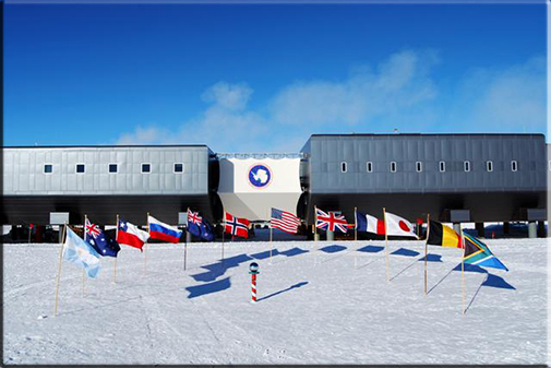
NSF Special Report U.S. South Pole Station: Supporting Science
Visit the South Pole webcam .
Read recent reports from South Pole Station , published in the Antarctic Sun .
Recent NSF press releases about the South Pole and research.
Americans have occupied the geographic South Pole continuously since November 1956. The station stands at an elevation of 2,835 meters (9,306 feet) on Antarctica's nearly featureless ice sheet, which is about 2,700 meters (9,000 feet) thick at that location. The station, which is 850 nautical miles south of McMurdo Station, is drifting with the ice sheet at about 10 meters (33 feet) each year.
Recorded temperature has varied between -13.6° C and -82.8° C. Annual mean is -49° C; monthly means vary from -28° C in December to -60° C in July. Average wind is 10.7 knots (12.3 miles per hour); peak gust recorded was 48 knots (55 miles per hour) in August 1989.
Snow accumulation is about 20 centimeters of snow (6-8 centimeters water equivalent) per year, with very low humidity.
The station's name honors Roald Amundsen and Robert F. Scott, who attained the South Pole in 1911 and 1912.
U.S. research stations at the geographic South Pole
The first station, built to support researchers during the International Geophysical Year, was begun in November 1956 and completed in February 1957. As interest in polar research increased, it became evident that a new design and a larger station was necessary.
In 1975 the central area of the station was rebuilt as a geodesic dome 50 meters wide and 16 meters high that, with 14- by 24-meter steel archways, covering modular buildings, fuel bladders, and equipment. Detached buildings housed instruments for monitoring the upper and lower atmosphere and for numerous and complex projects in astronomy and astrophysics. There is an emergency camp.
The dome facility was designed to house 18 science and support personnel during the winter and 33 during the austral summer. However, over the years, the facility's infrastructure and technology have exceeded its design and operational life. To augment the existing facility, a number of science and berthing structures were added in the 1990s, particularly for astronomy and astrophysics.
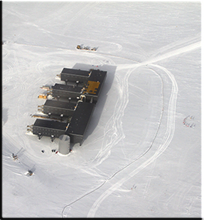
In 1997, a redevelopment plan to upgrade the station began. The new station, which was dedicated in 2008, is one connected, elevated facility. To accommodate changes in population from winter to summer, certain areas can be closed.
Remote science facilities are being developed with small one- to two-story elevated buildings and are located away from the main station to minimize interference between necessary operations and science.
As part of the elevated station, the existing arches were re-used for fuel storage, cargo, and waste management. New arches accommodate the garage shops and power plant. The benefits of elevated structures include reduced snow drifting, increased building life, diminished environmental impact, enhanced safety, maximized solar energy use, and more cost-effective construction.
Some 50 scientists and support personnel winter at the station, and up to 150 people work there during the summer. The station's winter personnel are isolated between mid-February and late October.
Support for science
The station has an Atmospheric Research Observatory, the Martin A. Pomerantz Observatory for astrophysics, and computer systems for research and communication including Internet access. It has collected the longest continuous set of meteorological data from Antarctica's vast interior ice plateau, and it is well located for studies of the cusp region of the magnetosphere. Astronomy and astrophysics have flourished in recent years, taking advantage of excellent optical properties of the atmosphere (resulting from its high elevation, low temperature, and low humidity) and, for neutrino detection, the extremely clear and homogeneous thick ice below. A small biomedical research facility is present. Other areas of interest include glaciology , geophysics and seismology, ocean and climate systems , astrophysics , astronomy , and biology .

- Donate/Online Payment
- Equipment Rental
- Facility Rental
- News & Resources
Research Station Drawings
We’re excited to share the exterior and floor plan drawings for the West Michigan Research Station. Big thanks to Lantern Homes, LLC for the drawings! Click to see the full size image.
Share This Story, Choose Your Platform!
Related posts.
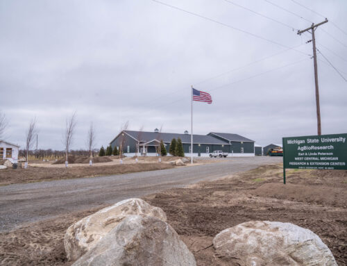
2020 Winter Update
Letter of support from senator jon bumstead, letter of support from rep. bill huizenga.
Jacques Cousteau’s grandson is building a network of ocean floor research stations
The first station will be off the coast of Curaçao, and it's scheduled to be completed by 2025.
By Charlotte Hu | Published Mar 4, 2022 3:00 PM EST
- Environment
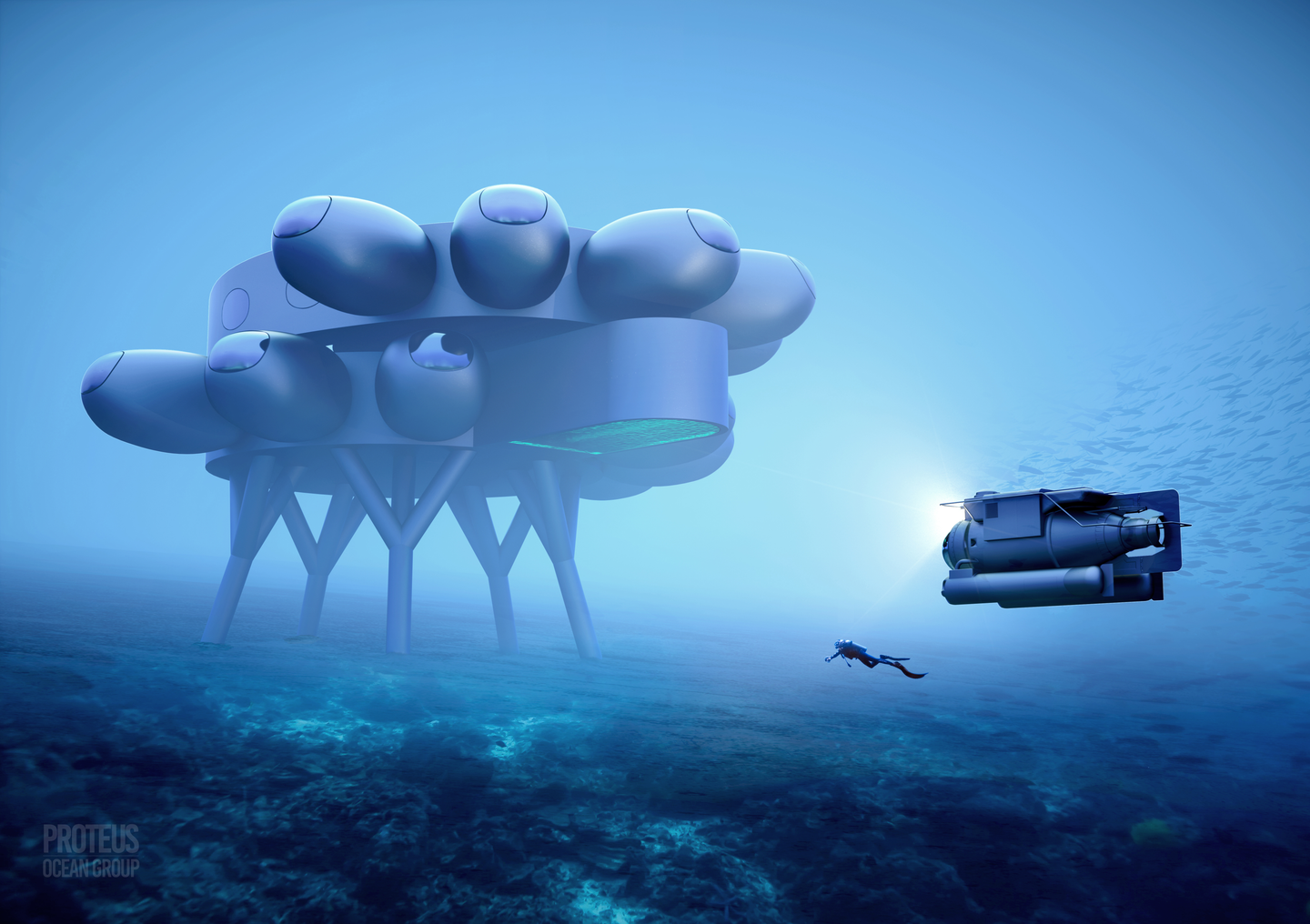
Fabien Cousteau has a vision for how humans can live and work in the ocean. He imagines that long-term stays under the waves could be enabled through the construction of underwater habitats, which would look and feel like houses, as opposed to just sealed, submarine-like bubbles.
These habitats would have a galley, kitchen, workspace, and sleeping quarters, he describes. And of course, there would be windows, or viewports, to the outside world, and a front door in the form of a moon pool that will actually be on the bottom of the house. This would allow easy access into and out of the facility.
The project, called Proteus, would be a marine analog to the International Space Station, and would primarily accommodate aquanauts, the equivalent of an astronaut in the ocean. It’s an idea that has been bubbling for some time now . But it could start taking shape relatively soon. Proteus Ocean Group , a private company which would operate and run Proteus, has recently signed an engineering, procurement, and construction (EPC) contract with a firm that has expertise in creating hyperbaric and pressure vessels in the ocean environment. Much of what Proteus is doing in terms of the technology they’re exploring is similar to space technology.
The first unit will be installed off of Curaçao, an island north of Venezuela, in a marine protected area around 60 feet deep. The team is looking into additional locations across Europe and the US for future stations— their goal is to create a network of them. They’ve already completed 3D mapping of the seafloor around the general area where Proteus will be located.
“We did our 3D benthic mapping , which was not a small feat during COVID. We already shared the maps with Carmabi and the government of Curaçao,” Cousteau, the grandson of ocean explorer Jacques Cousteau, says. They will start their front-end engineering design phase in April and pre-construct the parts either at the end of 2022 or in early 2023. If everything goes as scheduled, Proteus, along with a connected deeper water satellite station, is expected to be installed underwater by the end of 2025. A land-based mission control station will be built in parallel.

[Related: Boaty McBoatface’s new mission is more serious than its name ]
To appreciate how a facility like this could be helpful for the researchers that might one day live there, it helps to understand what separates it from traditional ocean technology, like a sub. “It’s very different from a submarine. A submarine is a bubble. Proteus and the deeper water station will not technically be pressure vessels,” Cousteau says. “The ambient pressure inside will be the same as the pressure outside. A pressure vessel is when you have a differential in pressure inside versus outside.”
He compares it to taking a cup, inverting it, and pushing it down into water. An air bubble would form inside, and water doesn’t go into the bubble because the pressures inside and outside the cup are at equilibrium. This would be useful for the explorers who live there because they don’t need to adjust and readjust to differing pressures inside and outside Proteus when leaving it to SCUBA dive.
What Proteus proposes is not a new idea. In fact, Cousteau’s grandfather was one of the early pioneers of underwater habitats in the 1960s. The History of Diving Museum estimates that over 60 seafloor habitats have been constructed, although most have been abandoned or have fallen to disrepair. The last standing one is Aquarius, located in the Florida Keys at a depth of 60 feet, which is still used to train astronauts and host research missions . In 2014, Fabien Cousteau stayed for 31 days at the reef base station, and shared an inside view of life under the waves with PopSci .
Some specs on the last remaining underwater research station
Originally, Aquarius was a joint project between NOAA and the US Navy. But since it was put in place in 1986, it has been passed to Florida International University. Aquarius consists of a three-part system : a habitat containing the lab and living spaces, a life-support buoy that relays air and communications from the habitat to the shore, and 120-ton base plate that weighs the habitat down on the seafloor. Beyond its scientific instruments , the lab has networked computers, internet, phones, radios, and video-conferencing equipment.

“An underwater lab gives us the ability to stay underwater for extended periods of time,” says Cousteau. That allows researchers to collect data around-the-clock. Plus, he adds, “You learn to saturate.”
A regular scuba diver descending to a depth of 60 feet can only stay underwater for an hour or so. Because rapid changes in pressure can cause dissolved gases in the body to form expanding bubbles that can obstruct blood flow or cause other medical issues, if they come up too quickly, it can cause what’s known as the Bends. This is also why divers have to wait up to a day after their last dive before they can get on a flight.
Saturation at depth allows the body to acclimate to the multiple atmospheres of pressure (60 feet corresponds to three atmospheres of pressure, or three times the pressure at the surface, and denizens of the facility would feel this new pressure all the time) and stay underwater for longer periods of time. When divers are ready to come up, they undergo a decompression process where the pressure around them is gradually brought back to the pressure on land so the gases can safely leave their body.
[Related: Fish sounds tell us about underwater reefs—but we need better tech to really listen ]
“We dove 8 to 12 hours a day per person during the [2014 mission on Aquarius] because of the gift of time at the bottom of the sea,” Cousteau says. “We were able to do three years worth of scientific research in 31 days as opposed to a ship stationed at the surface with divers coming down.”

But Aquarius is 35 years old. “It’s a dinosaur. And it’s very limited in space,” Cousteau says. “I joke with fellow New Yorkers that it’s like living in a studio apartment with five roommates.” The interior of Aquarius totals 400 sq ft and the capacity is 6 occupants. He is planning for Proteus to be around 4,000 sq ft, with room to accommodate around 12 residents.
Cousteau wants to add some new features too, like a submarine docking station or hangar, “akin to someone’s garage with a car, so that we can use that tool to go to places that are not pragmatic as aquanauts,” he says. The garage could also be used to deploy autonomous underwater vehicles that go out and collect data around the Caribbean. Then, they can come back to Proteus to get serviced and have their data downloaded.
The plan for Proteus
Like the ISS , Proteus would be modular, Cousteau hopes, which means that it could be taken apart like a Lego set and reassembled with upgraded tech components as time goes on. (Although unlike the ISS, it would not be a sealed facility.)
“We will be able to keep up with future demands, with technologies that continue to evolve,” Cousteau says. “You can continue to upgrade the internal infrastructure as well as some of the external superstructures.”
Curaçao is on a seamount. The underwater topography has an average slope of 45 degrees. If the location is just right, it could offer Proteus easy access to a wide range of ecosystems, spanning from coral reefs to the top of the twilight zone. “We want a place that’s conducive to research but engineering-wise, is not too complicated. And we want to be in close proximity to where mission control will be,” says Cousteau. “We are working with the government of Curaçao and Carmabi, the manager of the marine protected area, to be able to pinpoint the location.”
[Related: These free-floating robots can monitor the health of our oceans ]
The main components will borrow from proven technologies of habitats past. There will be wet labs, pressurized decompression chambers (to prepare aquanauts for resurfacing), a broadcast studio, a hydroponic garden , a larger sleeping space, and an umbilical connecting Proteus to a mission control station on land and to a deeper satellite habitat, located at around 230 feet below the surface.
The satellite habitat will be a heliox environment, meaning that the breathing gas is a mixture of helium and oxygen. Divers need special training for those conditions, and Cousteau will prepare higher-performing diving equipment and a heating system for that habitat. “For special missions, that will be available to smaller groups to do [a] much deeper kind of research,” Cousteau says. “Bear in mind if you’re saturated at 3 [atmospheres of pressure], you’re able to go down to 70 meters for 2 hours without any decompression obligations before going back to Proteus.”
The mission control facility on land will house infrastructure such as dry laboratories and health assessment rooms, and the umbilical to Proteus that can directly provide 16k broadcast capabilities, plus power, the cooling system, life support, fresh water, and breathing air. As a backup, Proteus will have secondary systems underwater that can sustain it for a few weeks in case the umbilical gets severed. Mission control will be able to provide the surface support, through boats, AUVs and submarines, that shuttle back and forth between land and Proteus.
Another key issue is food and other amenities. Chemistry works differently at three atmospheres. Even soap can be toxic at that pressure, he says. Add that to the fact that because there’s oxygen in the breathing air under pressure, there can’t be open flames for cooking or any other heat source that can ignite. This is where Proteus can borrow innovations and solutions from space technology.
Proteus will house a range of diving equipment that can allow for researchers to carry out experiments like selective breeding of families of corals, observing climate-change-related issues or weather patterns, deploying sensor arrays to count microplastic concentrations in the water column in real-time, examining a new species, or analyzing the chemical compositions of samples on site—all in the underwater lab without having to transport it long distances.

Cousteau is aiming for Proteus to be powered by renewable energy. “I’d love to be able to look at other sources of baseline energy generation [outside of wind and solar],” he notes. “For example, ocean thermal energy conversion, which is a proven technology but hasn’t been implemented in any large format.”
Mirjam Fürth, a professor of ocean engineering at Texas A&M University, has no doubt that Proteus will be able to do what it proposes by the time it gets its finances sorted. (It won’t be cheap: Forbes puts the price for building Proteus at $135 million. Proteus receives private funding as well as funding from Fabien Cousteau’s nonprofit, The Fabien Cousteau Ocean Learning Center) .
[Related: This tiny AI-powered robot is learning to explore the ocean on its own ]
But she points out that there might be certain technical challenges that come with scaling up that still need to be stress-tested. This issue boils down to the simple question around how they plan to get things in and out of their underwater home. For example, the submarine that they’re planning, is it supposed to enter through a giant moon pool or via an airlock? And how are food and other supplies going to be delivered for occupants?
“I think that’s why we haven’t seen [underwater habitats] at a large scale. Because a lot of these things are not linear when you scale up the complexity,” Fürth says. “Building something at a 60-feet depth is not complex, but having a large group of people living there for a prolonged period of time, some of which may not be experts—that’s what we haven’t seen before and that’s the hard thing that they’re going to need to tackle.”
The other factors that need to be considered include possible damage from hurricanes and underwater seismic activity, she adds. (Aquarius’ life support buoy was damaged by Hurricane Irma in 2017). Having an umbilical, as opposed to a buoy, could be “a lot safer in rough weather,” she says, though it might be more expensive.
However, despite these considerations, Fürth thinks that the materials and the technology that can enable Proteus to take form have been available for a while now. And it’s not the only company interested in such a project. A separate project, called SeaOrbital , has also been working on a floating spaceship lab in the ocean. The main hurdle for these ventures has been cost.
“That’s why I think it’s happening now,” she says, when they can capitalize on this new age of exploration and the rise of the blue economy . The “blue economy” is a term that encapsulates the growing interest in aquaculture (seaweed, shellfish, and more), wave energy and wind energy converters, and tech for desalination.
“The technology for robots has definitely leaped in the last decade and definitely in the last couple of years for marine applications,” she adds. “And the cost has come down significantly.”
“This drive of the blue economy has made people realize that there might be something here other than traditional fishing. I think this is part of it,” Fürth says. And in this new age of exploration, visiting a foreign world under the sea, rather than in space, “is something that is more attainable for people.”

Charlotte is the assistant technology editor at Popular Science. She’s interested in understanding how our relationship with technology is changing, and how we live online. Contact the author here.
Like science, tech, and DIY projects?
Sign up to receive Popular Science's emails and get the highlights.
- Hispanoamérica
- Work at ArchDaily
- Terms of Use
- Privacy Policy
- Cookie Policy
Train Stations: Examples of Floor Plans and Sections

- Written by María Francisca González | Translated by Emma Johansson
- Published on July 03, 2019

Train stations are usually complex programs since they must not only solve the departure and arrival of trains but also respond to the circulation of its users, provide certain services and be a connecting space between the transport systems of a city. Architects from different parts of the world have developed different solutions to this program. Below you can find 10 examples of train stations, their floor plans and sections.
Haramain High Speed Rail / Foster + Partners

King’s Cross Station / John McAslan + Partners

Napoli Afragola Station / Zaha Hadid Architects

Zürich Main Station / Dürig AG

Gare TGV de Montpellier, Montpellier Railway Station / Marc Mimram

HangZhou East Railway Station / CSADI

Graz Main Station Redevelopment / Zechner & Zechner

Birmingham New Street Station / AZPML

Porta Susa TGV Station / Silvio d’Ascia Architecture

Arnhem Central Transfer Terminal / UNStudio

- Sustainability
想阅读文章的中文版本吗?

You've started following your first account!
Did you know.
You'll now receive updates based on what you follow! Personalize your stream and start following your favorite authors, offices and users.

IMAGES
VIDEO
COMMENTS
Based on the report's findings, defense contractor Lockheed Martin, which manages the day-to-day operations at McMurdo for the NSF, hired OZ in August 2012 to create a master plan for the station. The Denver firm—with 130 employees, it's one of Colorado's largest—has a diverse portfolio, including single-family homes, condos, schools ...
Introduction. This document aims to provide guidance for the Design Process for future research spaces at. McGill. It is written for lab PIs, users, Project Managers, Professionals and Operation & Maintenance. people, who will execute a lab project from the Initial phase to the end of the project and who.
A well-designed modular plan will provide the following benefits: Flexibility—The lab module, as Jonas Salk explained, should "encourage change" within the building. Research is changing all the time, and buildings must allow for reasonable change. Many private research companies make physical changes to an average of 25% of their labs each year.
Building Type Basics for Research Laboratories, 2nd Edition by Daniel Watch. New York: John Wiley & Sons, Inc., 2008. ISBN# 978--470-16333-7. Guidelines for Planning and Design of Biomedical Research Laboratory Facilities by The American Institute of Architects, Center for Advanced Technology Facilities Design. Washington, D.C.:
Halley VI, on the freezing, floating Brunt Ice Shelf in Antarctica, is the world's first fully relocatable Polar research station, and was designed to provide a home from home for scientists working in one of the most extreme environments on earth. It is operated by the British Antarctic Survey (BAS). The modular design concept for Halley VI ...
Today's leading-edge research facilities speak of the importance and excitement of the research work. The design of a research center can significantly impact productivity, as well as the recruitment, morale and retention of researchers and staff.The laboratories are where researchers concentrate their time, and the environment speaks volumes about the perceived value of the work and the ...
international levels. Research granting agencies also impose health and safety conditions as a part of the research granting process. Health and safety is a moving target, with new hazards emerging from new research, coupled with a steady stream of new regulatory requirements. Meeting the compliance requirements of health and safety
555 Fayetteville Street, Suite 300 Raleigh, NC 27601 P 919-213-7007 3965 Fifth Avenue, Suite 400 San Diego, CA 92103 P 619-297-0159 www.rfd.com [email protected] RESEARCH FACILITIES DESIGN
Image 30 of 40 from gallery of Design Strategy & Research Center / THE_SYSTEM LAB. 2nd Floor Plan.
Second floor plan of the main research building. The second floor includes analytical laboratories, offices and the extensive mechanical space required for the facility. Meeting rooms and offices will be located at the bottom of the building. Above the meeting rooms will be a general analytical lab and computer geographic information system ...
To achieve the USAP science goals, NSF operates three U.S. scientific stations and two research vessels year-round on the continent. ... McMurdo Crary Lab Floor Plans. Amundsen-Scott South Pole Station Located 841 statute miles inland from McMurdo, at the geographic South Pole, this station accommodates a maximum of 250 people during the ...
The laboratory spaces were designed with flexibility and adaptability in mind to easily accommodate future changes in technology and research pursuits. This is specifically accomplished using a modular physical environment. Systematic and modular laboratory bays allow the building's floor plan to change depending on the department or function.
Science facilities require design that integrates specialty building systems, utilities and equipment with the human element of a pleasant working environment. Each laboratory, clean room or research space has unique environmental requirements, but all have a focus on efficiency, flexibility and safety at their core.
The station's name honors Roald Amundsen and Robert F. Scott, who attained the South Pole in 1911 and 1912. U.S. research stations at the geographic South Pole . The first station, built to support researchers during the International Geophysical Year, was begun in November 1956 and completed in February 1957.
By admin | 2020-03-05T15:40:01-05:00 March 5th, 2020 | Updates | Comments Off on Research Station Drawings Share This Story, Choose Your Platform! Facebook X Reddit LinkedIn WhatsApp Tumblr Pinterest Vk Email
Altogether, the project will result in fewer buildings, with roughly 370,000 square feet of new construction and will remove a number of aging and inefficient buildings. These upgrades will support the nation's cutting-edge science program in Antarctica and help ensure the United States maintains its position as a global leader in polar research.
The Amundsen-Scott South Pole Station is a United States scientific research station at the South Pole of the Earth. It is the southernmost point under the jurisdiction (not sovereignty) of the United States.The station is located on the high plateau of Antarctica at 9,301 feet (2,835 m) above sea level.It is administered by the Office of Polar Programs of the National Science Foundation ...
Crary Science and Engineering. Center (CSEC), McMurdo Station. Aerial photo of the Albert P. Crary Science and Engineering Center. The Crary buidling is the gray building with the three pods. The USAP Portal: Science and Support in Antarctica. Images of the Crary Science and Engineering Center (CSEC) floor plans.
Contexts in source publication. Context 1. ... wooden tables and chairs in rooms are mostly below 1.2 m. As shown in Figure 6, six readers were deployed in the fourth floor. Readers 1-3 were ...
Jacques Cousteau's grandson is building a network of ocean floor research stations. The first station will be off the coast of Curaçao, and it's scheduled to be completed by 2025. By Charlotte ...
This diagram illustrates a layout for a Large HQ station. This diagram also captures some of the key relationships for any combination station, regardless of size—in particular the need for separation of ARFF and Structural trucks relative to a flightline. Figure 2-4 Illustrative Layout Diagram C - Large HQ . 2.5.3 Sample Floor Plans
Grab a copy of Modern Floorplans: Arctic Research Station today, and keep an eye out for future releases! Map Description. Welcome to the Nevicata research station. Designed originally as an arctic research station, this building is perfect for any extreme weather. With its modular design, this structure can meet the needs of both big and small ...
Cite: María Francisca González. "Train Stations: Examples of Floor Plans and Sections" [Estación de Trenes: ejemplos en planta y sección] 03 Jul 2019. ArchDaily. (Trans. Johansson, Emma ...