- Forums New posts Search forums
- What's new New posts Latest activity
- Members Current visitors
AMD unveils Ryzen Pro 8000-series processors — Zen 4 and AI engines come to the commercial market

[SOLVED] Router not assigning IPv4
- Thread starter pmb88
- Start date May 25, 2020
Distinguished
- May 25, 2020
I have an issue reoccurring. I am using a Linksys E2500 router on Win 10. Lately on my PC some sites work like Facebook and Google, but can't access others. I tried to access router page using the default gateway 192.168.1.1, but it doesn't work. I noticed that on my network adapter has an IPv6 address, but no IPv4. I have to restart the router and modem several times. I had this router for several years, and this issue just started recently. I haven't done any changes to the router. Is the router reaching it's end?
- Jun 10, 2020
Your current router only has 100mbps ports so that is what is causing the 92mbps speedtest. Look for a router that has gigabit ports. You should be able to get something fairly good for $50-$60 range. Stay with the better brand routers. Even very inexpensive routers can do 1gbit wan/lan on ethernet. Wifi is going to be more limited by your end devices so don't be conned by big numbers. Lately almost all routers with number between 1200-1750 are only a few dollars different in price. You likely do not need anything with a bigger number.
pmb88 said: I have an issue reoccurring. I am using a Linksys E2500 router on Win 10. Lately on my PC some sites work like Facebook and Google, but can't access others. I tried to access router page using the default gateway 192.168.1.1, but it doesn't work. I noticed that on my network adapter has an IPv6 address, but no IPv4. I have to restart the router and modem several times. I had this router for several years, and this issue just started recently. I haven't done any changes to the router. Is the router reaching it's end? Click to expand...
- 2001:4860:4860::8888
- 2001:4860:4860::8844
Illustrious
Sounds like either 1) Time to get a new one or 2) Factory reset it and see if you can get it going again that way.
smithadamtries
- Disable IPV6 (Sometimes it interferes)
- Setup a Static IPV4 (try it with Static DNS.)
- Factory reset (It might not solve it if it's not a router settings problem, but worth trying!)
- May 26, 2020
Since nothing has changed in your configuration, I would book a linux live cd/usb to rule out any OS or hardware problems. If it doesn't work on the live cd, then I'd suspect hardware or network problems. I would also try wifi to see if that is any different. If wifi works and ethernet doesn't in linux, that points to a ethernet port going bad.
- May 29, 2020
- Assigning static ip - this didn't appear to work.
- Factory reset - it seemed to work nicely for a couple of days. However, the issue reoccurred yesterday.
pmb88 said: When the issue occurs, it occurs on any device whether they are connected via wifi or ethernet. Here's what I've tried since my post: Click to expand...
- May 30, 2020
It happened again yesterday. I directly connected to the modem and had no problems. So it seems to be something with the router.
- May 31, 2020
pmb88 said: It happened again yesterday. I directly connected to the modem and had no problems. So it seems to be something with the router. Click to expand...
- Jun 2, 2020
Since it has been determined that it is the router, then what would be a suitable replacement?
pmb88 said: Since it has been determined that it is the router, then what would be a suitable replacement? Click to expand...
SamirD said: How fast is your plan? Click to expand...
- Jun 7, 2020
pmb88 said: It's about 92 Mbps download, 25 Mbps upload Click to expand...
SamirD said: Is that a speed test or what you are paying for? Click to expand...
Your current router only has 100mbps ports so that is what is causing the 92mbps speedtest. Look for a router that has gigabit ports. You should be able to get something fairly good for $50-$60 range. Stay with the better brand routers. Even very inexpensive routers can do 1gbit wan/lan on ethernet. Wifi is going to be more limited by your end devices so don't be conned by big numbers. Lately almost all routers with number between 1200-1750 are only a few dollars different in price. You likely do not need anything with a bigger number.
TRENDING THREADS
- Started by Admin
- Today at 11:15 AM
- Replies: 26
- Started by knowledge2121
- Today at 12:06 PM
- Replies: 20
- Started by Kalnon
- Today at 5:11 PM
- Started by WrongRookie
- Today at 9:54 AM
- Replies: 13
- Started by Aquina
- Today at 5:25 PM
- Wednesday at 4:51 PM
- Replies: 35
- Started by Chris10199
- Today at 3:40 PM
Latest posts
- Latest: lantis3
- A moment ago
- Latest: pjw
- 9 minutes ago
- Latest: Lutfij
- 15 minutes ago
- Latest: hotaru.hino
- 24 minutes ago
- Latest: koberulz
- 28 minutes ago
- Latest: boju
- 36 minutes ago
- Latest: NedSmelly
- 48 minutes ago
Moderators online
Share this page
- Advertising
- Cookies Policies
- Term & Conditions
Stack Exchange Network
Stack Exchange network consists of 183 Q&A communities including Stack Overflow , the largest, most trusted online community for developers to learn, share their knowledge, and build their careers.
Q&A for work
Connect and share knowledge within a single location that is structured and easy to search.
What is IPv4 Autoconfiguration and why it overwrites static IP
I have to connect to a router with a static IP and subnet (machine automation, not internet). In ipconfig, subnet mask shows the subnet address I inputed but the IP is assigned a different one from the address I inputted. The previous computer connects properly and the only difference I notice in ipconfig is the new computer has "Autoconfiguration IPv4".
What is IPv4 Autoconfiguration? IP should be assigned from the router's DHCP, and if there is a IP-MAC conflict I should receive an error message. Why is IPv4 Autoconfiguration appear in PC's command prompt instead of the usual IPv4 in this case?
Googling yield a solution but that require modification of the registry to disable Autoconfiguration. I had already had the latest driver update. I suspect there is an alternative solution.

- wireless-networking
- Please provide a screenshot of the network connection’s IPv4 properties, where you entered your desired IP address etc. – Daniel B Aug 22, 2017 at 6:09
- Picture uploaded. As you see I set IP to be 100.0.0.255/255.255.0.0 but ipconfig shows Autoconfiguration IPv4 169.254.196.218/255.255.0.0 – KMC Aug 22, 2017 at 6:55
- It might be that Windows incorrectly assumes that .255 is an incorrect IP, but it is valid with that subnet mask. Did you try any other IP addresses? – Paul Aug 22, 2017 at 6:59
- Unfortunately I cannot since the device is fixed sending message only to 255. Why would OS autoconfiguration IPv4? Shouldn't that be the job of the router's DHCP? – KMC Aug 22, 2017 at 7:11
- Just making sure: You’re positive you set up the correct network adapter? – Daniel B Aug 22, 2017 at 7:19
6 Answers 6
The screenshot shows an IPv4 address that start with 169.254.
This is from the "link local" range (e.g., RFC 3927 page 31 discusses what Windows XP using these addresses). Some people call these addresses "APIPA" addresses, named after Windows XP's process called Automatic Private IP Assignment (APIPA).
It seems that as technology has advanced, there are now two causes that commonly resulting in an address in this range.
- Windows will use this if it is set to use DHCP, and it tries to get an address from a DHCP server, and fails.
- "Duplicate Address Detection" ("DAD") has resulted in noticing an IP address conflict. From the comments that have been made, it seems that the feature of "Duplicate Address Detection" detection may also result in automatically assigning a different IP address, even if an IP address is statically configured.
The potential fixes to having such an address can be:
- check the logs to see if there is anything mentioned about a duplicate IP address. If so, try to determine what other device had that address, and why it did. If it got that address by DHCP, try to determine which DHCP server was used by each address that got that address, and troubleshoot the DHCP server(s). (Note that accidentally having an unknown extra DHCP server might be a common cause for this.)
- get DHCP communication functioning successfully,
- or to go to the NIC properties and specify an "Alternate Configuration" process that uses a specified "User configuration", or to use a static IP address.
Why DHCP isn't working is a separate question. This is the correct answer for specifically what you asked, which is: "What is IPv4 Autoconfiguration".
As for why DCHP overwrites static IP: DHCP usually doesn't. If you see an Autoconfiguration address in Microsoft Windows, then you're not using a "static IP" assignment. (Instead, you're configured to be trying to use DHCP, or DAD is taking effect.)
According to one comment (which was made via a proposed suggested edit), newer versions of Microsoft Windows may silently set an autoconfig IP (instead of showing a message on the screen). This is likely caused by DAD.
Trying to disable DAD might not be a great way to fix the problem, as that may cause the computer to start working on the desired IP address, but not address the issue that another device is trying to use the same IP address (which may cause problems immediately, or later when the other device starts being more active again).
- It's worth noting that in the time since this answer was written, RFC 3927 has been rejected . – Brett Holman Jun 6, 2022 at 14:11
- 3 @BrettHolman I don't see that being the case. Having reviewed this (because I understand an RFC may be deprecated/obsoleted, but never heard of an RFC being "rejected"), I've determined that Errata ID 6293 has been rejected. Errata ID 6293 seems to be a proposed complaint/correction/update about RFC 3927, and this Errata was probably rejected due to a procedural concern: the rejector seems to indicate that if that text is going to be properly updated than that should happen by drafting a new RFC, not making an Errata on the old RFC. (So the RFC itself was never "rejected" that I can see.) – TOOGAM Jun 15, 2022 at 18:43
- Thank you for the clarification, I mistook the attached Errata rejection for rejection of the RFC. I really appreciate the response :) – Brett Holman Jun 16, 2022 at 14:38
As the alternative to editing registry you can try this solution:
- open command line
- check id of network connection - it will be in the 1st column: netsh interface ipv4 show inter
- run this command replacing <id> with id of your network connection: netsh interface ipv4 set interface <id> dadtransmits=0 store=persistent
- open services.msc and disable dhcp client
- disconnect network cable, restart computer, start dhcp client service and plug in network cable
source: http://the-it-wonders.blogspot.com/2013/04/autoconfiguration-ipv4-address-196254xx.html
Since I can't add comment to TOOGAM's answer: autoconfiguration apparently can overwrite static ip configuration. Today I had a laptop (with Windows 10, version 1709) that couldn't access network and had both static ip and autoconfiguration ip visible in ipconfig output even though I put static ip in network card configuration.
- Thanks jacob_w. This happened to us today too for no apparent reason, and your fix made it work. We've done many machines the same way and this is the first time we've seen this, so go figure. If anyone works out the actual reason this happens, please post. – radsdau Jun 12, 2018 at 6:11
- I feel pretty certain that steps 4 and 5 could be replaced by this: run IPConfig /release and then run IPConfig /renew . That may take a while, but would be faster (and easier) than the steps 4 and 5 provided, and would fully accomplish the critical steps that would happen by performing the longer steps 4 and 5 listed here. The basic reason either approach (either version of steps 4 and 5) would work is simply re-attempting a DHCP Discover or DHCP Request communication. – TOOGAM Dec 15, 2019 at 14:24
- If that works, the typical real problem is unreliability with the DHCP process. That could happen due to bad networking (bad center of cables, loose connection in the connectors of cables, wireless signal interference, filled DHCP scope which may randomly have an available address based on other devices)... maybe too many possible causes to list them all here, but not caused by a bad registry setting. – TOOGAM Dec 15, 2019 at 14:28
I had the same issue and in my case i had a static IP
So the Comment by another person "As for why it overwrites static IP: It doesn't. -- Is Incorrect
In my scenario it was one of the VMs and there was another VM with the same IP. Instead of throwing the error about duplicate IP in my case it performed Auto Configuration
- 1 this was my issue. i'm working with a printer that has a static ip of 192.168.123.100. I connected this printer to my laptop through ethernet, and also set the NIC ip to be 192.168.123.100, but because it conflicted with the printer's ip, the NIC defaulted back to 169.254. – Simon Sep 12, 2019 at 18:22
- On professionally-run networks I've encountered, we didn't typically have encounter duplicate addresses, so "duplicate address detection" wasn't actively affecting things. The " Obtain an IP address automatically " option basically boiled down to attempting DHCP, and if that failed, using the Alternate Configuration tab (which was usually unconfigured, resulting in APIPA assigning an IPv4 (169.254.*) link-local address. The " Use the following address " option resulted in a static IP, not causing DHCP or Link-Local to work. – TOOGAM Dec 15, 2019 at 14:41
- I suspect that if Duplicate Address Detection (DAD) is being particularly useful, that may be because of some sort of issue with DHCP (e.g., server doesn't exist on the LAN being used, which may be quite likely with some "virtual machine" setups... or a filled DHCP scope, which may be remedied with an increased scope size or figuring out what is using up the addresses in an existing scope). My inclination would be to figure out why DHCP is not being a working, reliable solution, and trying to address that as a problem. (Of course, that works for me, who knows how to set up/troubleshoot DHCP) – TOOGAM Dec 15, 2019 at 14:44
- 1 Question is about static IP – SeanClt Dec 15, 2019 at 15:21
I had the same issue. I read that this is because the NIC card is not working properly, even though the Ethernet card said it was working properly. I have an HP desktop computer. I went to HP support, downloaded and reinstalled the Realtek Ethernet Controller Drivers for it and it fixed the card problem. No more autoconfiguration ipv4 address. Hope this help others.
- 2 You say "No more autoconfiguration ipv4 address." But that's wrong, based on the output you quote, as the output says " Autoconfiguration Enabled . . . . : Yes ". What is true is that you didn't get an Autoconfiguration address from the "Link-local" (IPv4 169.254.*) range. Instead, your Autoconfiguration successfully got an address from the DHCP server, which is identified in your output on the line that says " DHCP Server . . . . . . . . . . . : 172.16.0.1 ". So whatever device is at 172.16.0.1 (which is also your Default Gateway, so is some type of router) served you well, with DHCP. – TOOGAM Dec 15, 2019 at 14:32
Its caused by a conflicting IP address. (Someone else on the same network has the same IP).
Changing the static IP helped me, but i am aware its not always practical. For me it worked because i connect to this computer alone.
- 1 Your answer could be improved with additional supporting information. Please edit to add further details, such as citations or documentation, so that others can confirm that your answer is correct. You can find more information on how to write good answers in the help center . – Community Bot May 4, 2023 at 12:06
I had the same issue.
I had a hyper-v instance with several network adapters, all set with static IP addresses.
One instance was set up with 8 network adapters, all static IP. One adapter would have an auto configured ipv4 169 address, eventhough I set it with a static IP. Very frustrating, and after trying many other things I figured it out. It had been set with a static IP address that was already taken by another device. Simply changing the static IP address fixed the autoconfigured 169 issue.
You must log in to answer this question.
Not the answer you're looking for browse other questions tagged windows-10 wireless-networking router ipv4 ..
- The Overflow Blog
- How do you evaluate an LLM? Try an LLM.
- Why configuration is so complicated
- Featured on Meta
- New Focus Styles & Updated Styling for Button Groups
- Upcoming initiatives on Stack Overflow and across the Stack Exchange network
- Google Cloud will be Sponsoring Super User SE
Hot Network Questions
- The Variational form of a biharmonic PDE
- Measuring the resistance of an LED -> getting conflicting values
- Forest plot to show results in a observational restrospective cohort study
- Reviewer rejects a paper and then publishes the same results as their own?
- Can two interfering light beams create radio waves?
- Level shift a 0-20 V pulse to +,-10 V without deteriorating the rise time
- Mechanism used to automatically turn on headlights?
- Slight cut on finger during biometrics
- What was Silk Spectre II's relationship with superheroics?
- Why doesn't the liquid in a liquid-in-glass thermometer slide down when you turn it upside-down?
- Is this Python/Pygame that draws a maze well structured?
- Companies carrying out private investigations and prosecutions
- Does Casting Enlarge/Reduce on a College-of-Creation-Bard's Dancing Item Cause that Item to be Inanimate?
- Success of Aggressive Rebuttal Strategy
- which refers to what?
- Enforce contract on burglars
- Identify this children's Commodore 64 book
- Is there an infinite number of logic systems?
- Interesting third degree polynomial
- Can you tile a 25 x 25 square with a mixture of 2 x 2 squares and 3 x 3 squares?
- Supressing proton and neutron decay?
- Looking for the specific font in the screen shot
- Is anything other than metals soluble in molten metals/alloys?
- How to convert the form of a solution from solve {x -> 1, y -> 1, z -> Sqrt[2]} into a list form {1, 1, Sqrt[2]}?
- Skip to content
- Skip to search
- Skip to footer
IP Addressing: IPv4 Addressing Configuration Guide, Cisco IOS XE Release 3S
Bias-free language.
The documentation set for this product strives to use bias-free language. For the purposes of this documentation set, bias-free is defined as language that does not imply discrimination based on age, disability, gender, racial identity, ethnic identity, sexual orientation, socioeconomic status, and intersectionality. Exceptions may be present in the documentation due to language that is hardcoded in the user interfaces of the product software, language used based on RFP documentation, or language that is used by a referenced third-party product. Learn more about how Cisco is using Inclusive Language.
Configuring IPv4 Addresses
- IP Overlapping Address Pools
- IP Unnumbered Ethernet Polling Support
- Zero Touch Auto-IP

Chapter: Configuring IPv4 Addresses
Finding feature information, information about ip addresses, binary numbering, ip address structure, ip address classes, ip network subnetting, ip network address assignments, classless inter-domain routing, how to configure ip addresses, establishing ip connectivity to a network by assigning an ip address to an interface, troubleshooting tips, increasing the number of ip hosts that are supported on a network by using secondary ip addresses, what to do next, maximizing the number of available ip subnets by allowing the use of ip subnet zero, specifying the format of network masks, specifying the format in which netmasks appear for the current session, specifying the format in which netmasks appear for an individual line, using ip unnumbered interfaces on point-to-point wan interfaces to limit number of ip addresses required, ip unnumbered feature, using ip addresses with 31-bit prefixes on point-to-point wan interfaces to limit number of ip addresses required, configuration examples for ip addresses, example establishing ip connectivity to a network by assigning an ip address to an interface, example increasing the number of ip hosts that are supported on a network by using secondary ip addresses, example using ip unnumbered interfaces on point-to-point wan interfaces to limit number of ip addresses required, example using ip addresses with 31-bit prefixes on point-to-point wan interfaces to limit number of ip addresses required, example maximizing the number of available ip subnets by allowing the use of ip subnet zero, where to go next, additional references, feature information for ip addresses.
This chapter contains information about, and instructions for configuring IPv4 addresses on interfaces that are part of a networking device.
Your software release may not support all the features documented in this module. For the latest caveats and feature information, see Bug Search Tool and the release notes for your platform and software release. To find information about the features documented in this module, and to see a list of the releases in which each feature is supported, see the feature information table at the end of this module.
Use Cisco Feature Navigator to find information about platform support and Cisco software image support. To access Cisco Feature Navigator, go to www.cisco.com/go/cfn . An account on Cisco.com is not required.
IP addresses are 32 bits long. The 32 bits are divided into four octets (8-bits). A basic understanding of binary numbering is very helpful if you are going to manage IP addresses in a network because changes in the values of the 32 bits indicate either a different IP network address or IP host address.
A value in binary is represented by the number (0 or 1) in each position multiplied by the number 2 to the power of the position of the number in sequence, starting with 0 and increasing to 7, working right to left. The figure below is an example of an 8-digit binary number.

The figure below provides binary to decimal number conversion for 0 through 134.

The figure below provides binary to decimal number conversion for 135 through 255.

An IP host address identifies a device to which IP packets can be sent. An IP network address identifies a specific network segment to which one or more hosts can be connected. The following are characteristics of IP addresses:
IP addresses are 32 bits long
IP addresses are divided into four sections of one byte (octet) each
IP addresses are typically written in a format known as dotted decimal
The table below shows some examples of IP addresses.
IP addresses are further subdivided into two sections known as network and host. The division is accomplished by arbitrarily ranges of IP addresses to classes. For more information see RFC 791 Internet Protocol at http://www.ietf.org/rfc/rfc0791.txt .
In order to provide some structure to the way IP addresses are assigned, IP addresses are grouped into classes. Each class has a range of IP addresses. The range of IP addresses in each class is determined by the number of bits allocated to the network section of the 32-bit IP address. The number of bits allocated to the network section is represented by a mask written in dotted decimal or with the abbreviation / n where n = the numbers of bits in the mask.
The table below lists ranges of IP addresses by class and the masks associated with each class. The digits in bold indicate the network section of the IP address for each class. The remaining digits are available for host IP addresses. For example, IP address 10.90.45.1 with a mask of 255.0.0.0 is broken down into a network IP address of 10.0.0.0 and a host IP address of 0.90.45.1.
When a digit that falls within the network mask changes from 1 to 0 or 0 to 1 the network address is changed. For example, if you change 10101100.00010000.01011001.00100010/16 to 10101100.00110000.01011001.00100010/16 you have changed the network address from 172.16.89.34/16 to 172.48.89.34/16.
When a digit that falls outside the network mask changes from 1 to 0 or 0 to 1 the host address is changed. For example, if you change 10101100.00010000.01011001.00100010/16 to 10101100.00010000.01011001.00100011/16 you have changed the host address from 172.16.89.34/16 to 172.16.89.35/16.
Each class of IP address supports a specific range of IP network addresses and IP host addresses. The range of IP network addresses available for each class is determined with the formula 2 to the power of the number of available bits. In the case of class A addresses, the value of the first bit in the 1st octet (as shown in the table above) is fixed at 0. This leaves 7 bits for creating additional network addresses. Therefore there are 128 IP network addresses available for class A (27 = 128).
The number of IP host addresses available for an IP address class is determined by the formula 2 to the power of the number of available bits minus 2. There are 24 bits available in a class A addresses for IP host addresses. Therefore there are 16,777,214 IP hosts addresses available for class A ((224) - 2 = 16,777,214)).
The table below shows the network and host addresses available for each class of IP address.
The arbitrary subdivision of network and host bits in IP address classes resulted in an inefficient allocation of IP space. For example, if your network has 16 separate physical segments you will need 16 IP network addresses. If you use 16 class B IP network addresses, you would be able to support 65,534 hosts on each of the physical segments. Your total number of supported host IP addresses is 1,048,544 (16 * 65,534 = 1,048,544). Very few network technologies can scale to having 65,534 hosts on a single network segment. Very few companies need 1,048,544 IP host addresses. This problem required the development of a new strategy that permitted the subdivision of IP network addresses into smaller groupings of IP subnetwork addresses. This strategy is known as subnetting.
If your network has 16 separate physical segments you will need 16 IP subnetwork addresses. This can be accomplished with one class B IP address. For example, start with the class B IP address of 172.16.0.0 you can reserve 4 bits from the third octet as subnet bits. This gives you 16 subnet IP addresses 24 = 16. The table below shows the IP subnets for 172.16.0.0/20.
When a digit that falls within the subnetwork (subnet) mask changes from 1 to 0 or 0 to 1 the subnetwork address is changed. For example, if you change 10101100.00010000.01011001.00100010/20 to 10101100.00010000.01111001.00100010/20 you have changed the network address from 172.16.89.34/20 to 172.16.121.34/20.
When a digit that falls outside the subnet mask changes from 1 to 0 or 0 to 1 the host address is changed. For example, if you change 10101100.00010000.01011001.00100010/20 to 10101100.00010000.01011001.00100011/20 you have changed the host address from 172.16.89.34/20 to 172.16.89.35/20.
Some people get confused about the terms network address and subnet or subnetwork addresses and when to use them. In the most general sense the term network address means “the IP address that routers use to route traffic to a specific network segment so that the intended destination IP host on that segment can receive it”. Therefore the term network address can apply to both non-subnetted and subnetted IP network addresses. When you are troubleshooting problems with forwarding traffic from a router to a specific IP network address that is actually a subnetted network address, it can help to be more specific by referring to the destination network address as a subnet network address because some routing protocols handle advertising subnet network routes differently from network routes. For example, the default behavior for RIP v2 is to automatically summarize the subnet network addresses that it is connected to their non-subnetted network addresses (172.16.32.0/24 is advertised by RIP v2 as 172.16.0.0/16) when sending routing updates to other routers. Therefore the other routers might have knowledge of the IP network addresses in the network, but not the subnetted network addresses of the IP network addresses.
Routers keep track of IP network addresses to understand the network IP topology (layer 3 of the OSI reference model) of the network to ensure that IP traffic can be routed properly. In order for the routers to understand the network layer (IP) topology, every individual physical network segment that is separated from any other physical network segment by a router must have a unique IP network address.
The figure below shows an example of a simple network with correctly configured IP network addresses. The routing table in R1 looks like the table below.

The figure below shows an example of a simple network with incorrectly configured IP network addresses. The routing table in R1 looks like the table below. If the PC with IP address 172.31.32.3 attempts to send IP traffic to the PC with IP address 172.31.32.54, router R1 cannot determine which interface that the PC with IP address 172.31.32.54 is connected to.

To help prevent mistakes as shown in the figure above, Cisco IOS-based networking devices will not allow you to configure the same IP network address on two or more interfaces in the router when IP routing is enabled.
The only way to prevent the mistake shown in the figure below, where 172.16.31.0/24 is used in R2 and R3, is to have very accurate network documentation that shows where you have assigned IP network addresses.

For a more thorough explanation of IP routing, see the "Related Documents" section for a list of documents related to IP routing.
Due to the continuing increase in internet use and the limitations on how IP addresses can be assigned using the class structure shown in the table above, a more flexible method for allocating IP addresses was required. The new method is documented in RFC 1519 Classless Inter-Domain Routing (CIDR): an Address Assignment and Aggregation Strategy . CIDR allows network administrators to apply arbitrary masks to IP addresses to create an IP addressing plan that meets the requirements of the networks that they administrate.
For more information on CIDR, refer to RFC 1519 at http://www.ietf.org/rfc/rfc1519.txt .
The term prefix is often used to refer to the number of bits of an IP network address that are of importance for building routing tables. If you are using only classful (strict adherence to A, B, and C network address boundaries) IP addresses, the prefixes are the same as the masks for the classes of addresses. For example, using classful IP addressing, a class C IP network address such as 192.168.10.0 uses a 24-bit mask (/24 or 255.255.255.0) and can also be said to have a 24-bit prefix.
If you are using CIDR, the prefixes are arbitrarily assigned to IP network addresses based on how you want to populate the routing tables in your network. For example, a group of class C IP addresses such as 192.168.10.0, 192.168.11.0, 192.168.12.0, 192.168.13.0 can be advertised as a single route to 192.168.0.0 with a 16-bit prefix (192.168.0.0/16). This results in a 4:1 reduction in the number of routes that the routers in your network need to manage.
Perform this task to configure an IP address on an interface.
1. enable
2. configure terminal
3. interface type number
4. no shutdown
5. ip address ip-address mask
The following commands can help troubleshoot IP addressing:
show ip interface --Displays the IP parameters for the interface.
show ip route connected --Displays the IP networks the networking device is connected to.
If you have a situation in which you need to connect more IP hosts to a network segment and you have used all of the available IP host addresses for the subnet to which you have assigned the segment, you can avoid having to readdress all of the hosts with a different subnet by adding a second IP network address to the network segment.
Perform this task to configure a secondary IP address on an interface.
6. ip address ip-address mask secondary
If your network has two or more routers and you have already configured a routing protocol, make certain that the other routers can reach the new IP network that you assigned. You might need to modify the configuration for the routing protocol on the router so that it advertises the new network. Consult the Cisco IOS IP Routing: Protocol-Independent Configuration Guide for information on configuring routing protocols.
If you using subnetting in your network and you are running out of network addresses, you can configure your networking device to allow the configuration of subnet zero. This adds one more usable network address for every subnet in your IP addressing scheme. The table above shows the IP subnets (including subnet 0) for 172.16.0.0/20.
Perform this task to enable the use of IP subnet zero on your networking device.
3. ip subnet-zero
4. interface type number
5. no shutdown
6. ip address ip-address mask
By default, show commands display an IP address and then its netmask in dotted decimal notation. For example, a subnet would be displayed as 131.108.11.55 255.255.255.0.
You might find it more convenient to display the network mask in hexadecimal format or bit count format instead. The hexadecimal format is commonly used on UNIX systems. The previous example would be displayed as 131.108.11.55 0XFFFFFF00.
The bit count format for displaying network masks is to append a slash (/) and the total number of bits in the netmask to the address itself. The previous example would be displayed as 131.108.11.55/24.
Perform this task to specify the format in which netmasks appear for the current session.
2. term ip netmask-format { bitcount | decimal | hexadecimal }
Perform this task to specify the format in which netmasks appear for an individual line.
3. line vty first last
4. term ip netmask-format { bitcount | decimal | hexadecimal }
If you have a limited number of IP network or subnet addresses and you have point-to-point WANs in your network, you can use the IP Unnumbered Interfaces feature to enable IP connectivity on the point-to-point WAN interfaces without actually assigning an IP address to them.
Perform this task to configure the IP Unnumbered Interfaces feature on a point-to-point WAN interface.
The IP Unnumbered Interfaces feature enables IP processing on a point-to-point WAN interface without assigning it an explicit IP address. The IP unnumbered point-to-point WAN interface uses the IP address of another interface to enable IP connectivity, which conserves network addresses.
6. interface type number
7. no shutdown
8. ip unnumbered type number
You can reduce the number of IP subnets used by networking devices to establish IP connectivity to point-to-point WANs that they are connected to by using IP Addresses with 31-bit Prefixes as defined in RFC 3021.
Perform this task to configure an IP address with a 31-bit prefix on a point-to-point WAN interface.
Prior to RFC 3021, Using 31-bit Prefixes on IPv4 Point-to-Point Links , many network administrators assigned IP address with a 30-bit subnet mask (255.255.255.252) to point-to-point interfaces to conserve IP address space. Although this practice does conserve IP address space compared to assigning IP addresses with shorter subnet masks such as 255.255.255.240, IP addresses with a 30-bit subnet mask still require four addresses per link: two host addresses (one for each host interface on the link), one all-zeros network address, and one all-ones broadcast network address.
The table below shows an example of the four IP addresses that are created when a 30-bit (otherwise known as 255.255.255.252 or /30) subnet mask is applied to the IP address 192.168.100.4. The bits that are used to specify the host IP addresses in bold.
Point-to-point links only have two endpoints (hosts) and do not require broadcast support because any packet that is transmitted by one host is always received by the other host. Therefore the all-ones broadcast IP address is not required for a point-to-point interface.
The simplest way to explain RFC 3021 is to say that the use of a 31-bit prefix (created by applying a 31-bit subnet mask to an IP address) allows the all-zeros and all-ones IP addresses to be assigned as host addresses on point-to-point networks. Prior to RFC 3021 the longest prefix in common use on point-to-point links was 30-bits, which meant that the all-zeros and all-ones IP addresses were wasted.
The table below shows an example of the two IP addresses that are created when a 31-bit (otherwise known as 255.255.255.254 or /31) subnet mask is applied to the IP address 192.168.100.4. The bit that is used to specify the host IP addresses in bold
The complete text for RFC 3021 is available at http://www.ietf.org/rfc/rfc3021.txt .
You must have classless IP addressing configured on your networking device before you configure an IP address with a 31-bit prefix on a point-to-point interface. Classless IP addressing is enabled by default in many versions of Cisco IOS software. If you are not certain that your networking device has IP classless addressing configured, enter the ip classless command in global configuration mode to enable it.
3. ip classless
Specifies a point-to-point WAN interface and enters interface configuration mode.
Enables the interface.
Configures the 31bit prefix IP address on the point-to-point WAN interface.
Exits the current configuration mode and returns to privileged EXEC mode.
The following example configures an IP address on three interfaces:
The following example configures secondary IP addresses on three interfaces:
The following example configures the unnumbered IP feature on three interfaces:
The following example configures 31-bit prefixes on two interfaces:
The following example enables subnet zero:
If your network has two or more routers and you have not already configured a routing protocol, consult the Cisco IOS IP Routing Protocols Configuration Guide , Release 12.4T, for information on configuring routing protocols.
Related Documents
Technical assistance.
The following table provides release information about the feature or features described in this module. This table lists only the software release that introduced support for a given feature in a given software release train. Unless noted otherwise, subsequent releases of that software release train also support that feature.
Contents Configuring IPv4 Addresses Finding Feature Information Information About IP Addresses Binary Numbering IP Address Structure IP Address Classes IP Network Subnetting IP Network Address Assignments Classless Inter-Domain Routing Prefixes How to Configure IP Addresses Establishing IP Connectivity to a Network by Assigning an IP Address to an Interface Troubleshooting Tips Increasing the Number of IP Hosts that Are Supported on a Network by Using Secondary IP Addresses Troubleshooting Tips What to Do Next Maximizing the Number of Available IP Subnets by Allowing the Use of IP Subnet Zero Troubleshooting Tips Specifying the Format of Network Masks Specifying the Format in Which Netmasks Appear for the Current Session Specifying the Format in Which Netmasks Appear for an Individual Line Using IP Unnumbered Interfaces on Point-to-Point WAN Interfaces to Limit Number of IP Addresses Required IP Unnumbered Feature Troubleshooting Tips Using IP addresses with 31-Bit Prefixes on Point-to-Point WAN Interfaces to Limit Number of IP Addresses Required RFC 3021 Troubleshooting Tips Configuration Examples for IP Addresses Example Establishing IP Connectivity to a Network by Assigning an IP Address to an Interface Example Increasing the Number of IP Hosts that are Supported on a Network by Using Secondary IP Addresses Example Using IP Unnumbered Interfaces on Point-to-Point WAN Interfaces to Limit Number of IP Addresses Required Example Using IP addresses with 31-Bit Prefixes on Point-to-Point WAN Interfaces to Limit Number of IP Addresses Required Example Maximizing the Number of Available IP Subnets by Allowing the Use of IP Subnet Zero Where to Go Next Additional References Feature Information for IP Addresses Configuring IPv4 Addresses This chapter contains information about, and instructions for configuring IPv4 addresses on interfaces that are part of a networking device. Note All further references to IPv4 addresses in this document use only IP in the text, not IPv4. Finding Feature Information Information About IP Addresses How to Configure IP Addresses Configuration Examples for IP Addresses Where to Go Next Additional References Feature Information for IP Addresses Finding Feature Information Your software release may not support all the features documented in this module. For the latest caveats and feature information, see Bug Search Tool and the release notes for your platform and software release. To find information about the features documented in this module, and to see a list of the releases in which each feature is supported, see the feature information table at the end of this module. Use Cisco Feature Navigator to find information about platform support and Cisco software image support. To access Cisco Feature Navigator, go to www.cisco.com/go/cfn . An account on Cisco.com is not required. Information About IP Addresses Binary Numbering IP Address Structure IP Address Classes IP Network Subnetting IP Network Address Assignments Classless Inter-Domain Routing Prefixes Binary Numbering IP addresses are 32 bits long. The 32 bits are divided into four octets (8-bits). A basic understanding of binary numbering is very helpful if you are going to manage IP addresses in a network because changes in the values of the 32 bits indicate either a different IP network address or IP host address. A value in binary is represented by the number (0 or 1) in each position multiplied by the number 2 to the power of the position of the number in sequence, starting with 0 and increasing to 7, working right to left. The figure below is an example of an 8-digit binary number. Figure 1. Example of an 8-digit Binary Number The figure below provides binary to decimal number conversion for 0 through 134. Figure 2. Binary to Decimal Number Conversion for 0 to 134 The figure below provides binary to decimal number conversion for 135 through 255. Figure 3. Binary to Decimal Number Conversion for 135 to 255 IP Address Structure An IP host address identifies a device to which IP packets can be sent. An IP network address identifies a specific network segment to which one or more hosts can be connected. The following are characteristics of IP addresses: IP addresses are 32 bits long IP addresses are divided into four sections of one byte (octet) each IP addresses are typically written in a format known as dotted decimal The table below shows some examples of IP addresses. Table 1 Examples of IP Addresses IP Addresses in Dotted Decimal IP Addresses in Binary 10.34.216.75 00001010.00100010.11011000.01001011 172.16.89.34 10101100.00010000.01011001.00100010 192.168.100.4 11000000.10101000.01100100.00000100 Note The IP addresses in the table above are from RFC 1918, Address Allocation for Private Internets . These IP addresses are not routable on the Internet. They are intended for use in private networks. For more information on RFC1918, see http://www.ietf.org/rfc/rfc1918.txt . IP addresses are further subdivided into two sections known as network and host. The division is accomplished by arbitrarily ranges of IP addresses to classes. For more information see RFC 791 Internet Protocol at http://www.ietf.org/rfc/rfc0791.txt . IP Address Classes In order to provide some structure to the way IP addresses are assigned, IP addresses are grouped into classes. Each class has a range of IP addresses. The range of IP addresses in each class is determined by the number of bits allocated to the network section of the 32-bit IP address. The number of bits allocated to the network section is represented by a mask written in dotted decimal or with the abbreviation / n where n = the numbers of bits in the mask. The table below lists ranges of IP addresses by class and the masks associated with each class. The digits in bold indicate the network section of the IP address for each class. The remaining digits are available for host IP addresses. For example, IP address 10.90.45.1 with a mask of 255.0.0.0 is broken down into a network IP address of 10.0.0.0 and a host IP address of 0.90.45.1. Table 2 IP Address Ranges by Class with Masks Class Range A (range/mask in dotted decimal) 0 .0.0.0 to 127.0.0.0/8 (255.0.0.0) A (range in binary) 00000000 .00000000.00000000.00000000 to 01111111 .00000000.00000000.00000000 A (mask in binary) 11111111.00000000.00000000.00000000/8 B (range/mask in dotted decimal) 128 .0.0.0 to 191 . 255 .0.0/16 (255.255.0.0) B (range in binary) 10000000 . 00000000 .00000000.00000000 to 10111111 . 11111111 .00000000.00000000 B (mask in binary) 11111111 . 11111111 .00000000.00000000/16 C (range/mask in dotted decimal) 192 . 0 . 0 .0 to 223 . 255 . 255 .0/24 (255.255.255.0) C (range in binary) 11000000 . 00000000 . 00000000 .00000000 to 11011111 . 11111111 . 11111111 .00000000 C (mask in binary) 11111111.11111111.11111111.0000000/24 D 1 (range/mask in dotted decimal) 224 . 0 . 0 . 0 to 239 . 255 . 255 . 255 /32 (255.255.255.255) D (range in binary) 11100000 . 00000000 . 00000000 . 00000000 to 11101111 . 11111111 . 11111111 . 11111111 D (mask in binary) 11111111.11111111.11111111.11111111/32 E 2 (range/mask in dotted decimal) 240 . 0 . 0 . 0 to 255 . 255 . 255 . 255 /32 (255.255.255.255) E (range in binary) 11110000 . 00000000 . 00000000 . 00000000 to 11111111 . 11111111 . 11111111 . 11111111 E (mask in binary) 11111111.11111111.11111111.11111111/32 1 Class D IP addresses are reserved for multicast applications. 2 Class E IP addresses are reserved for broadcast traffic. Note Some IP addresses in these ranges are reserved for special uses. For more information refer to RFC 3330, Special-Use IP Addresses , at http://www.ietf.org/rfc/rfc3330.txt . When a digit that falls within the network mask changes from 1 to 0 or 0 to 1 the network address is changed. For example, if you change 10101100.00010000.01011001.00100010/16 to 10101100.00110000.01011001.00100010/16 you have changed the network address from 172.16.89.34/16 to 172.48.89.34/16. When a digit that falls outside the network mask changes from 1 to 0 or 0 to 1 the host address is changed. For example, if you change 10101100.00010000.01011001.00100010/16 to 10101100.00010000.01011001.00100011/16 you have changed the host address from 172.16.89.34/16 to 172.16.89.35/16. Each class of IP address supports a specific range of IP network addresses and IP host addresses. The range of IP network addresses available for each class is determined with the formula 2 to the power of the number of available bits. In the case of class A addresses, the value of the first bit in the 1st octet (as shown in the table above) is fixed at 0. This leaves 7 bits for creating additional network addresses. Therefore there are 128 IP network addresses available for class A (27 = 128). The number of IP host addresses available for an IP address class is determined by the formula 2 to the power of the number of available bits minus 2. There are 24 bits available in a class A addresses for IP host addresses. Therefore there are 16,777,214 IP hosts addresses available for class A ((224) - 2 = 16,777,214)). Note The 2 is subtracted because there are 2 IP addresses that cannot be used for a host. The all 0’s host address cannot be used because it is the same as the network address. For example, 10.0.0.0 cannot be both a IP network address and an IP host address. The all 1’s address is a broadcast address that is used to reach all hosts on the network. For example, an IP datagram addressed to 10.255.255.255 will be accepted by every host on network 10.0.0.0. The table below shows the network and host addresses available for each class of IP address. Table 3 Network and Host Addresses Available for Each Class of IP Address Class Network Addresses Host Addresses A 128 16,777,214 B 16,384 3 65534 C 2,097,152 4 254 3 Only 14 bits are available for class B IP network addresses because the first 2 bits are fixed at 10 as shown in Table 2 . 4 Only 21 bits are available for class C IP network addresses because the first 3 bits are fixed at 110 as shown in Table 2 . IP Network Subnetting The arbitrary subdivision of network and host bits in IP address classes resulted in an inefficient allocation of IP space. For example, if your network has 16 separate physical segments you will need 16 IP network addresses. If you use 16 class B IP network addresses, you would be able to support 65,534 hosts on each of the physical segments. Your total number of supported host IP addresses is 1,048,544 (16 * 65,534 = 1,048,544). Very few network technologies can scale to having 65,534 hosts on a single network segment. Very few companies need 1,048,544 IP host addresses. This problem required the development of a new strategy that permitted the subdivision of IP network addresses into smaller groupings of IP subnetwork addresses. This strategy is known as subnetting. If your network has 16 separate physical segments you will need 16 IP subnetwork addresses. This can be accomplished with one class B IP address. For example, start with the class B IP address of 172.16.0.0 you can reserve 4 bits from the third octet as subnet bits. This gives you 16 subnet IP addresses 24 = 16. The table below shows the IP subnets for 172.16.0.0/20. Table 4 Examples of IP Subnet Addresses using 172.16.0.0/20 Number IP Subnet Addresses in Dotted Decimal IP Subnet Addresses in Binary 0 5 172.16.0.0 10101100.00010000.00000000.00000000 1 172.16.16.0 10101100.00010000.00010000.00000000 2 172.16.32.0 10101100.00010000.00100000.00000000 3 172.16.48.0 10101100.00010000.00110000.00000000 4 172.16.64.0 10101100.00010000.01000000.00000000 5 172.16.80.0 10101100.00010000.01010000.00000000 6 172.16.96.0 10101100.00010000.01100000.00000000 7 172.16.112.0 10101100.00010000.01110000.00000000 8 172.16.128.0 10101100.00010000.10000000.00000000 9 172.16.144.0 10101100.00010000.10010000.00000000 10 172.16.160.0 10101100.00010000.10100000.00000000 11 172.16.176.0 10101100.00010000.10110000.00000000 12 172.16.192.0 10101100.00010000.11000000.00000000 13 172.16.208.0 10101100.00010000.11010000.00000000 14 172.16.224.0 10101100.00010000.11100000.00000000 15 172.16.240.0 10101100.00010000.11110000.00000000 5 The first subnet that has all of the subnet bits set to 0 is referred to as subnet 0 . It is indistinguishable from the network address and must be used carefully. When a digit that falls within the subnetwork (subnet) mask changes from 1 to 0 or 0 to 1 the subnetwork address is changed. For example, if you change 10101100.00010000.01011001.00100010/20 to 10101100.00010000.01111001.00100010/20 you have changed the network address from 172.16.89.34/20 to 172.16.121.34/20. When a digit that falls outside the subnet mask changes from 1 to 0 or 0 to 1 the host address is changed. For example, if you change 10101100.00010000.01011001.00100010/20 to 10101100.00010000.01011001.00100011/20 you have changed the host address from 172.16.89.34/20 to 172.16.89.35/20. Timesaver To avoid having to do manual IP network, subnetwork, and host calculations, use one of the free IP subnet calculators available on the Internet. Some people get confused about the terms network address and subnet or subnetwork addresses and when to use them. In the most general sense the term network address means “the IP address that routers use to route traffic to a specific network segment so that the intended destination IP host on that segment can receive it”. Therefore the term network address can apply to both non-subnetted and subnetted IP network addresses. When you are troubleshooting problems with forwarding traffic from a router to a specific IP network address that is actually a subnetted network address, it can help to be more specific by referring to the destination network address as a subnet network address because some routing protocols handle advertising subnet network routes differently from network routes. For example, the default behavior for RIP v2 is to automatically summarize the subnet network addresses that it is connected to their non-subnetted network addresses (172.16.32.0/24 is advertised by RIP v2 as 172.16.0.0/16) when sending routing updates to other routers. Therefore the other routers might have knowledge of the IP network addresses in the network, but not the subnetted network addresses of the IP network addresses. Tip The term IP address space is sometimes used to refer to a range of IP addresses. For example, “We have to allocate a new IP network address to our network because we have used all of the available IP addresses in the current IP address space”. IP Network Address Assignments Routers keep track of IP network addresses to understand the network IP topology (layer 3 of the OSI reference model) of the network to ensure that IP traffic can be routed properly. In order for the routers to understand the network layer (IP) topology, every individual physical network segment that is separated from any other physical network segment by a router must have a unique IP network address. The figure below shows an example of a simple network with correctly configured IP network addresses. The routing table in R1 looks like the table below. Table 5 Routing Table for a Correctly Configured Network Interface Ethernet 0 Interface Ethernet 1 172.31.32.0/24 (Connected) 172.31.16.0/24 (Connected) Figure 4. Correctly Configured Network The figure below shows an example of a simple network with incorrectly configured IP network addresses. The routing table in R1 looks like the table below. If the PC with IP address 172.31.32.3 attempts to send IP traffic to the PC with IP address 172.31.32.54, router R1 cannot determine which interface that the PC with IP address 172.31.32.54 is connected to. Table 6 Routing Table in Router R1 for an Incorrectly Configured Network (Example 1) Ethernet 0 Ethernet 1 172.31.32.0/24 (Connected) 172.31.32.0/24 (Connected) Figure 5. Incorrectly Configured Network (Example 1) To help prevent mistakes as shown in the figure above, Cisco IOS-based networking devices will not allow you to configure the same IP network address on two or more interfaces in the router when IP routing is enabled. The only way to prevent the mistake shown in the figure below, where 172.16.31.0/24 is used in R2 and R3, is to have very accurate network documentation that shows where you have assigned IP network addresses. Table 7 Routing Table in Router R1 for an Incorrectly Configured Network (Example 2) Ethernet 0 Serial 0 Serial 1 172.16.32.0/24 (Connected) 192.168.100.4/29 (Connected) 172.16.31.0/24 RIP 192.168.100.8/29 (Connected) 172.16.31.0/24 RIP Figure 6. Incorrectly Configured Network (Example 2) For a more thorough explanation of IP routing, see the "Related Documents" section for a list of documents related to IP routing. Classless Inter-Domain Routing Due to the continuing increase in internet use and the limitations on how IP addresses can be assigned using the class structure shown in the table above, a more flexible method for allocating IP addresses was required. The new method is documented in RFC 1519 Classless Inter-Domain Routing (CIDR): an Address Assignment and Aggregation Strategy . CIDR allows network administrators to apply arbitrary masks to IP addresses to create an IP addressing plan that meets the requirements of the networks that they administrate. For more information on CIDR, refer to RFC 1519 at http://www.ietf.org/rfc/rfc1519.txt . Prefixes The term prefix is often used to refer to the number of bits of an IP network address that are of importance for building routing tables. If you are using only classful (strict adherence to A, B, and C network address boundaries) IP addresses, the prefixes are the same as the masks for the classes of addresses. For example, using classful IP addressing, a class C IP network address such as 192.168.10.0 uses a 24-bit mask (/24 or 255.255.255.0) and can also be said to have a 24-bit prefix. If you are using CIDR, the prefixes are arbitrarily assigned to IP network addresses based on how you want to populate the routing tables in your network. For example, a group of class C IP addresses such as 192.168.10.0, 192.168.11.0, 192.168.12.0, 192.168.13.0 can be advertised as a single route to 192.168.0.0 with a 16-bit prefix (192.168.0.0/16). This results in a 4:1 reduction in the number of routes that the routers in your network need to manage. How to Configure IP Addresses Establishing IP Connectivity to a Network by Assigning an IP Address to an Interface Increasing the Number of IP Hosts that Are Supported on a Network by Using Secondary IP Addresses Maximizing the Number of Available IP Subnets by Allowing the Use of IP Subnet Zero Specifying the Format of Network Masks Using IP Unnumbered Interfaces on Point-to-Point WAN Interfaces to Limit Number of IP Addresses Required Using IP addresses with 31-Bit Prefixes on Point-to-Point WAN Interfaces to Limit Number of IP Addresses Required Establishing IP Connectivity to a Network by Assigning an IP Address to an Interface Perform this task to configure an IP address on an interface. SUMMARY STEPS 1. enable 2. configure terminal 3. interface type number 4. no shutdown 5. ip address ip-address mask 6. end DETAILED STEPS Command or Action Purpose Step 1 enable Example: Router> enable Enables privileged EXEC mode. Enter your password if prompted. Step 2 configure terminal Example: Router# configure terminal Enters global configuration mode. Step 3 interface type number Example: Router(config)# interface fastethernet 0/0 Specifies an interface and enters interface configuration mode. Step 4 no shutdown Example: Router(config-if)# no shutdown Enables the interface. Step 5 ip address ip-address mask Example: Router(config-if)# ip address 172.16.16.1 255.255.240.0 Configures the IP address on the interface. Step 6 end Example: Router(config-if)# end Exits the current configuration mode and returns to privileged EXEC mode. Troubleshooting Tips The following commands can help troubleshoot IP addressing: show ip interface --Displays the IP parameters for the interface. show ip route connected --Displays the IP networks the networking device is connected to. Increasing the Number of IP Hosts that Are Supported on a Network by Using Secondary IP Addresses If you have a situation in which you need to connect more IP hosts to a network segment and you have used all of the available IP host addresses for the subnet to which you have assigned the segment, you can avoid having to readdress all of the hosts with a different subnet by adding a second IP network address to the network segment. Perform this task to configure a secondary IP address on an interface. SUMMARY STEPS 1. enable 2. configure terminal 3. interface type number 4. no shutdown 5. ip address ip-address mask 6. ip address ip-address mask secondary 7. end DETAILED STEPS Command or Action Purpose Step 1 enable Example: Router> enable Enables privileged EXEC mode. Enter your password if prompted. Step 2 configure terminal Example: Router# configure terminal Enters global configuration mode. Step 3 interface type number Example: Router(config)# interface fastethernet 0/0 Specifies an interface and enters interface configuration mode. Step 4 no shutdown Example: Router(config-if)# no shutdown Enables the interface. Step 5 ip address ip-address mask Example: Router(config-if)# ip address 172.16.16.1 255.255.240.0 Configures the IP address on the interface. Step 6 ip address ip-address mask secondary Example: Router(config-if)# ip address 172.16.32.1 255.255.240.0 secondary Configures the secondary IP address on the interface. Step 7 end Example: Router(config-if)# end Exits the current configuration mode and returns to privileged EXEC mode. Troubleshooting Tips The following commands can help troubleshoot IP addressing: show ip interface --Displays the IP parameters for the interface. show ip route connected --Displays the IP networks the networking device is connected to. What to Do Next If your network has two or more routers and you have already configured a routing protocol, make certain that the other routers can reach the new IP network that you assigned. You might need to modify the configuration for the routing protocol on the router so that it advertises the new network. Consult the Cisco IOS IP Routing: Protocol-Independent Configuration Guide for information on configuring routing protocols. Maximizing the Number of Available IP Subnets by Allowing the Use of IP Subnet Zero If you using subnetting in your network and you are running out of network addresses, you can configure your networking device to allow the configuration of subnet zero. This adds one more usable network address for every subnet in your IP addressing scheme. The table above shows the IP subnets (including subnet 0) for 172.16.0.0/20. Perform this task to enable the use of IP subnet zero on your networking device. SUMMARY STEPS 1. enable 2. configure terminal 3. ip subnet-zero 4. interface type number 5. no shutdown 6. ip address ip-address mask 7. end DETAILED STEPS Command or Action Purpose Step 1 enable Example: Router> enable Enables privileged EXEC mode. Enter your password if prompted. Step 2 configure terminal Example: Router# configure terminal Enters global configuration mode. Step 3 ip subnet-zero Example: Router(config)# ip subnet-zero Enables the use of IP subnet zero. Step 4 interface type number Example: Router(config)# interface fastethernet 0/0 Specifies an interface and enters interface configuration mode. Step 5 no shutdown Example: Router(config-if)# no shutdown Enables the interface. Step 6 ip address ip-address mask Example: Router(config-if)# ip address 172.16.0.1 255.255.240.0 Configures the subnet zero IP address on the interface. Step 7 end Example: Router(config-if)# end Exits the current configuration mode and returns to privileged EXEC mode. Troubleshooting Tips The following commands can help troubleshoot IP addressing: show ip interface --Displays the IP parameters for the interface. show ip route connected --Displays the IP networks the networking device is connected to. Specifying the Format of Network Masks By default, show commands display an IP address and then its netmask in dotted decimal notation. For example, a subnet would be displayed as 131.108.11.55 255.255.255.0. You might find it more convenient to display the network mask in hexadecimal format or bit count format instead. The hexadecimal format is commonly used on UNIX systems. The previous example would be displayed as 131.108.11.55 0XFFFFFF00. The bit count format for displaying network masks is to append a slash (/) and the total number of bits in the netmask to the address itself. The previous example would be displayed as 131.108.11.55/24. Specifying the Format in Which Netmasks Appear for the Current Session Specifying the Format in Which Netmasks Appear for an Individual Line Specifying the Format in Which Netmasks Appear for the Current Session Perform this task to specify the format in which netmasks appear for the current session. SUMMARY STEPS 1. enable 2. term ip netmask-format { bitcount | decimal | hexadecimal } DETAILED STEPS Command or Action Purpose Step 1 enable Example: Router> enable Enables privileged EXEC mode. Enter your password if prompted. Step 2 term ip netmask-format { bitcount | decimal | hexadecimal } Example: Router# term ip netmask-format hexadecimal Specifies the format the router uses to display network masks. Specifying the Format in Which Netmasks Appear for an Individual Line Perform this task to specify the format in which netmasks appear for an individual line. SUMMARY STEPS 1. enable 2. configure terminal 3. line vty first last 4. term ip netmask-format { bitcount | decimal | hexadecimal } 5. end DETAILED STEPS Command or Action Purpose Step 1 enable Example: Router> enable Enables privileged EXEC mode. Enter your password if prompted. Step 2 configure terminal Example: Router# configure terminal Enters global configuration mode. Step 3 line vty first last Example: Router(config)# line vty 0 4 Enters line configuration mode for the range of lines specified by the first and last arguments. Step 4 term ip netmask-format { bitcount | decimal | hexadecimal } Example: Router(config-line)# ip netmask-format hexadecimal Specifies the format the router uses to display the network mask for an individual line. Step 5 end Example: Router(config-if)# end Exits the current configuration mode and returns to privileged EXEC mode. Using IP Unnumbered Interfaces on Point-to-Point WAN Interfaces to Limit Number of IP Addresses Required If you have a limited number of IP network or subnet addresses and you have point-to-point WANs in your network, you can use the IP Unnumbered Interfaces feature to enable IP connectivity on the point-to-point WAN interfaces without actually assigning an IP address to them. Perform this task to configure the IP Unnumbered Interfaces feature on a point-to-point WAN interface. IP Unnumbered Feature Troubleshooting Tips IP Unnumbered Feature The IP Unnumbered Interfaces feature enables IP processing on a point-to-point WAN interface without assigning it an explicit IP address. The IP unnumbered point-to-point WAN interface uses the IP address of another interface to enable IP connectivity, which conserves network addresses. Note The following restrictions apply to the IP Unnumbered Interfaces feature: The IP Unnumbered Interfaces feature is only supported on point-to-point (non-multiaccess) WAN interfaces You cannot netboot a Cisco IOS image over an interface that is using the IP Unnumbered Interfaces feature SUMMARY STEPS 1. enable 2. configure terminal 3. interface type number 4. no shutdown 5. ip address ip-address mask 6. interface type number 7. no shutdown 8. ip unnumbered type number 9. end DETAILED STEPS Command or Action Purpose Step 1 enable Example: Router> enable Enables privileged EXEC mode. Enter your password if prompted. Step 2 configure terminal Example: Router# configure terminal Enters global configuration mode. Step 3 interface type number Example: Router(config)# interface fastethernet 0/0 Specifies an interface and enters interface configuration mode. Step 4 no shutdown Example: Router(config-if)# no shutdown Enables the interface. Step 5 ip address ip-address mask Example: Router(config-if)# ip address 172.16.16.1 255.255.240.0 Configures the IP address on the interface. Step 6 interface type number Example: Router(config-if)# interface serial 0/0 Specifies a point-to-point WAN interface and enters interface configuration mode. Step 7 no shutdown Example: Router(config-if)# no shutdown Enables the point-to-point WAN interface. Step 8 ip unnumbered type number Example: Router(config-if)# ip unnumbered fastethernet 0/0 Enables the IP unnumbered feature on the point-to-point WAN interface. In this example the point-to-point WAN interface uses IP address 172.16.16.1 from Fast Ethernet 0/0. Step 9 end Example: Router(config-if)# end Exits the current configuration mode and returns to privileged EXEC mode. Troubleshooting Tips The following commands can help troubleshoot IP addressing: show ip interface --Displays the IP parameters for the interface. show ip route connected --Displays the IP networks the networking device is connected to. Using IP addresses with 31-Bit Prefixes on Point-to-Point WAN Interfaces to Limit Number of IP Addresses Required You can reduce the number of IP subnets used by networking devices to establish IP connectivity to point-to-point WANs that they are connected to by using IP Addresses with 31-bit Prefixes as defined in RFC 3021. Perform this task to configure an IP address with a 31-bit prefix on a point-to-point WAN interface. RFC 3021 Troubleshooting Tips RFC 3021 Prior to RFC 3021, Using 31-bit Prefixes on IPv4 Point-to-Point Links , many network administrators assigned IP address with a 30-bit subnet mask (255.255.255.252) to point-to-point interfaces to conserve IP address space. Although this practice does conserve IP address space compared to assigning IP addresses with shorter subnet masks such as 255.255.255.240, IP addresses with a 30-bit subnet mask still require four addresses per link: two host addresses (one for each host interface on the link), one all-zeros network address, and one all-ones broadcast network address. The table below shows an example of the four IP addresses that are created when a 30-bit (otherwise known as 255.255.255.252 or /30) subnet mask is applied to the IP address 192.168.100.4. The bits that are used to specify the host IP addresses in bold. Table 8 Four IP Addresses Created When a 30-Bit Subnet Mask (/30) Is Used Address Description Binary 192.168.100.4/30 All-zeros IP address 11000000.10101000.01100100.000001 00 192.168.100.5/30 First host addresses 11000000.10101000.01100100.000001 01 192.168.100.6/30 Second host address 11000000.10101000.01100100.000001 10 192.168.100.7/30 All-ones broadcast address 11000000.10101000.01100100.000001 11 Point-to-point links only have two endpoints (hosts) and do not require broadcast support because any packet that is transmitted by one host is always received by the other host. Therefore the all-ones broadcast IP address is not required for a point-to-point interface. The simplest way to explain RFC 3021 is to say that the use of a 31-bit prefix (created by applying a 31-bit subnet mask to an IP address) allows the all-zeros and all-ones IP addresses to be assigned as host addresses on point-to-point networks. Prior to RFC 3021 the longest prefix in common use on point-to-point links was 30-bits, which meant that the all-zeros and all-ones IP addresses were wasted. The table below shows an example of the two IP addresses that are created when a 31-bit (otherwise known as 255.255.255.254 or /31) subnet mask is applied to the IP address 192.168.100.4. The bit that is used to specify the host IP addresses in bold Table 9 Two IP Addresses Created When a 31-Bit Subnet Mask (/31) Is Used Address Description Binary 192.168.100.4/31 First host address 11000000.10101000.01100100.0000010 0 192.168.100.5/31 Second host address 11000000.10101000.01100100.0000010 1 The complete text for RFC 3021 is available at http://www.ietf.org/rfc/rfc3021.txt . Before You Begin You must have classless IP addressing configured on your networking device before you configure an IP address with a 31-bit prefix on a point-to-point interface. Classless IP addressing is enabled by default in many versions of Cisco IOS software. If you are not certain that your networking device has IP classless addressing configured, enter the ip classless command in global configuration mode to enable it. Note This task can only be performed on point-to-point (nonmultiaccess) WAN interfaces. SUMMARY STEPS 1. enable 2. configure terminal 3. ip classless 4. interface type number 5. no shutdown 6. ip address ip-address mask 7. end DETAILED STEPS Command or Action Purpose Step 1 enable Example: Router> enable Enables privileged EXEC mode. Enter your password if prompted. Step 2 configure terminal Example: Router# configure terminal Enters global configuration mode. Step 3 ip classless Example: Router(config)# ip classless (Optional) Enables IP classless (CIDR). Note This command is enabled by default in many versions of Cisco IOS. If you are not certain if it is enabled by default in the version of Cisco IOS that your networking device is running, enter the ip classless command as shown. When you are done with this task view the configuration. If the ip classless command does not appear in your configuration, it is enabled by default. Step 4 interface type number Example: Router(config)# interface serial 0/0 Specifies a point-to-point WAN interface and enters interface configuration mode. Step 5 no shutdown Example: Router(config-if)# no shutdown Enables the interface. Step 6 ip address ip-address mask Example: Router(config-if)# ip address 192.168.100.4 255.255.255.254 Configures the 31bit prefix IP address on the point-to-point WAN interface. Step 7 end Example: Router(config-if)# end Exits the current configuration mode and returns to privileged EXEC mode. Troubleshooting Tips The following commands can help troubleshoot IP addressing: show ip interface --Displays the IP parameters for the interface. show ip route connected --Displays the IP networks the networking device is connected to. Configuration Examples for IP Addresses Example Establishing IP Connectivity to a Network by Assigning an IP Address to an Interface Example Increasing the Number of IP Hosts that are Supported on a Network by Using Secondary IP Addresses Example Using IP Unnumbered Interfaces on Point-to-Point WAN Interfaces to Limit Number of IP Addresses Required Example Using IP addresses with 31-Bit Prefixes on Point-to-Point WAN Interfaces to Limit Number of IP Addresses Required Example Maximizing the Number of Available IP Subnets by Allowing the Use of IP Subnet Zero Example Establishing IP Connectivity to a Network by Assigning an IP Address to an Interface The following example configures an IP address on three interfaces: ! interface FastEthernet0/0 no shutdown ip address 172.16.16.1 255.255.240.0 ! interface FastEthernet0/1 no shutdown ip address 172.16.32.1 255.255.240.0 ! interface FastEthernet0/2 no shutdown ip address 172.16.48.1 255.255.240.0 ! Example Increasing the Number of IP Hosts that are Supported on a Network by Using Secondary IP Addresses The following example configures secondary IP addresses on three interfaces: ! interface FastEthernet0/0 no shutdown ip address 172.16.16.1 255.255.240.0 ip address 172.16.32.1 255.255.240.0 secondary ! ! interface FastEthernet0/1 no shutdown ip address 172.17.16.1 255.255.240.0 ip address 172.17.32.1 255.255.240.0 secondary ! ! interface FastEthernet0/2 no shutdown ip address 172.18.16.1 255.255.240.0 ip address 172.18.32.1 255.255.240.0 secondary ! Example Using IP Unnumbered Interfaces on Point-to-Point WAN Interfaces to Limit Number of IP Addresses Required The following example configures the unnumbered IP feature on three interfaces: ! interface FastEthernet0/0 no shutdown ip address 172.16.16.1 255.255.240.0 ! interface serial0/0 no shutdown ip unnumbered fastethernet0/0 ! interface serial0/1 no shutdown ip unnumbered fastethernet0/0 ! interface serial0/2 no shutdown ip unnumbered fastethernet0/0 ! Example Using IP addresses with 31-Bit Prefixes on Point-to-Point WAN Interfaces to Limit Number of IP Addresses Required The following example configures 31-bit prefixes on two interfaces: ! ip classless ! interface serial0/0 no shutdown ip address 192.168.100.2 255.255.255.254 ! ! interface serial0/1 no shutdown ip address 192.168.100.4 255.255.255.254 Example Maximizing the Number of Available IP Subnets by Allowing the Use of IP Subnet Zero The following example enables subnet zero: ! interface FastEthernet0/0 no shutdown ip address 172.16.16.1 255.255.240.0 ! ip subnet-zero ! Where to Go Next If your network has two or more routers and you have not already configured a routing protocol, consult the Cisco IOS IP Routing Protocols Configuration Guide , Release 12.4T, for information on configuring routing protocols. Additional References Related Documents Related Topic Document Title Cisco IOS commands Cisco IOS Master Commands List, All Releases IP addressing commands: complete command syntax, command mode, command history, defaults, usage guidelines, and examples Cisco IOS IP Addressing Services Command Reference Fundamental principles of IP addressing and IP routing IP Routing Primer ISBN 1578701082 Standards Standard Title No new or modified standards are supported, and support for existing standards has not been modified -- MIBs MIB MIBs Link No new or modified MIBs are supported, and support for existing MIBs has not been modified To locate and download MIBs for selected platforms, Cisco software releases, and feature sets, use Cisco MIB Locator found at the following URL: http://www.cisco.com/go/mibs RFCs RFC 6 Title RFC 791 Internet Protocol http://www.ietf.org/rfc/rfc0791.txt RFC 1338 Classless Inter-Domain Routing (CIDR): an Address Assignment and Aggregation Strategy http://www.ietf.org/rfc/rfc1519.txt RFC 1466 Guidelines for Management of IP Address Space http://www.ietf.org/rfc/rfc1466.txt RFC 1716 Towards Requirements for IP Routers http://www.ietf.org/rfc/rfc1716.txt RFC 1918 Address Allocation for Private Internets http://www.ietf.org/rfc/rfc1918.txt RFC 3330 Special-Use IP Addresses http://www.ietf.org/rfc/rfc3330.txt 6 These references are only a sample of the many RFCs available on subjects related to IP addressing and IP routing. Refer to the IETF RFC site at http://www.ietf.org/rfc.html for a full list of RFCs. Technical Assistance Description Link The Cisco Support and Documentation website provides online resources to download documentation, software, and tools. Use these resources to install and configure the software and to troubleshoot and resolve technical issues with Cisco products and technologies. Access to most tools on the Cisco Support and Documentation website requires a Cisco.com user ID and password. http://www.cisco.com/cisco/web/support/index.htmll Feature Information for IP Addresses The following table provides release information about the feature or features described in this module. This table lists only the software release that introduced support for a given feature in a given software release train. Unless noted otherwise, subsequent releases of that software release train also support that feature. Use Cisco Feature Navigator to find information about platform support and Cisco software image support. To access Cisco Feature Navigator, go to www.cisco.com/go/cfn . An account on Cisco.com is not required. Table 10 Feature Information for IP Addresses Feature Name Releases Feature Information Classless Inter-Domain Routing 10.0 CIDR is a new way of looking at IP addresses that eliminates the concept of classes (class A, class B, and so on). For example, network 192.213.0.0, which is an illegal class C network number, is a legal supernet when it is represented in CIDR notation as 192.213.0.0/16. The /16 indicates that the subnet mask consists of 16 bits (counting from the left). Therefore, 192.213.0.0/16 is similar to 192.213.0.0 255.255.0.0. The following command was introduced or modified: ip classless . IP Subnet Zero 10.0 In order to conserve IP address space IP Subnet Zero allows the use of the all-zeros subnet as an IP address on an interface, such as configuring 172.16.0.1/24 on Fast Ethernet 0/0. The following command was introduced or modified: ip subnet-zero . IP Unnumbered Interfaces 10.0 In order to conserve IP address space, IP unnumbered interfaces use the IP address of another interface to enable IP connectivity. The following command was introduced or modified: ip unnumbered . Using 31-bit Prefixes on IP Point-to-Point Links 12.0(14)S 12.2(4)T In order to conserve IP address space on the Internet, a 31-bit prefix length allows the use of only two IP addresses on a point-to-point link. Previously, customers had to use four IP addresses or unnumbered interfaces for point-to-point links.
Was this Document Helpful?

Contact Cisco
- (Requires a Cisco Service Contract )

Contribute to the Windows forum! Click here to learn more 💡
April 9, 2024
Contribute to the Windows forum!
Click here to learn more 💡
Windows 10 Top Forum Contributors: neilpzz - Ramesh Srinivasan - _AW_ - questions_ - Volume Z 👍✅
April 17, 2024
Windows 10 Top Forum Contributors:
neilpzz - Ramesh Srinivasan - _AW_ - questions_ - Volume Z 👍✅
- Search the community and support articles
- Search Community member
Ask a new question
Static IP Address Assignment - Does Not Work
Two of my PC's are identical PC Sticks to which I need to sometimes remote in using their names and sometimes I need to remote into them using their IP addresses. They both run Win10 Pro, remote desktop is enabled and I am easily able to remote into both of them and take control. However, these two somehow act differently when static IP is being assigned.
PC "A" is fine. I go through the process of assigning a static IP address, do an ipconfig, and I see the assigned address, and I am able to remote into it using that static IP address. PC "B" does not respond in that way. If I vary the IP address from what is automatically assigned to it, the last number field in the address, and if it is different from the number assigned automatically, it doesn't take - in other words when I do an ipconfig I continue seeing the old IP address that was automatically assigned to it.
I have looked over various settings and compared them and the two PC's are identical in every aspect, including the WiFi driver hardware, driver, driver version and driver date. What do you think may be the problem that keeps the static IP address from being assigned?
Thanks in advance.
Report abuse
Replies (3) .
After setting a fixed IP address, what do you see when you reopen the adapter's IP settings? Do you see the adress you set or did it flip back to DHCP?
Maybe your account has insufficient privileges to modify the relevant registry entries. You can find them here:
HKEY_LOCAL_MACHINE\SYSTEM\CurrentControlSet\Services\Tcpip\Parameters\Interfaces
Your current network adapters are found here:
HKEY_LOCAL_MACHINE\SYSTEM\CurrentControlSet\Control\Class\{4d36e972-e325-11ce-bfc1-08002be10318}
The NetCfgInstanceId corresponds to the key name under the Interfaces key.
Was this reply helpful? Yes No
Sorry this didn't help.
Great! Thanks for your feedback.
How satisfied are you with this reply?
Thanks for your feedback, it helps us improve the site.
Thanks for your feedback.
Hi Fredrick.
An automatic IP assignment is: 192.168.0.17
If I change that to 192.168.0.18 then ipconfig reports Autoconfiguration IPV4 169.254.240.70.
If I set the IP to be automatically assigned, then ipconfig reports IPV4 Address 192.168.0.17 again.
I have looked at the HKEY_stuff and they are way ver my head. I must be doing something wrong in between these two exact - I mean exact computers.
Thanks for the input.
SOLVED THE PROBLEM.
Considering identical computers and identical software, I finally powered the router down and powered it back up, and the problem went away.
1 person found this reply helpful
Question Info
- Internet and connectivity
- Norsk Bokmål
- Ελληνικά
- Русский
- עברית
- العربية
- ไทย
- 한국어
- 中文(简体)
- 中文(繁體)
- 日本語
How to configure a static IP on Windows 10 or 11
Do you need to switch from a dynamic to a static IP address configuration on Windows 11 or 10? Here's how.

- Windows 11 static IP
- Windows 10 static IP
On Windows, the router's Dynamic Host Configuration Protocol (DHCP) server is (usually) responsible for assigning a dynamic Transmission Control Protocol/Internet Protocol (TCP/IP) configuration to every device in the network, including to your computer running Windows 11 or Windows 10.
Although a dynamic IP address is the recommended configuration for most situations, you may need to change to a static IP address if you're thinking about setting up a printer or file sharing, or you have to configure port forwarding on the router to your computer.
The reason is that a dynamic network configuration can change at any time after the lease from the DHCP expires and if the address changes, network resources you may have configured will stop working. Setting a static IP address will always stay the same on the computer, allowing a more reliable experience sharing resources in the network or forwarding ports.
Whatever the reason, on Windows 10 and 11, you have many ways to configure a static TCP/IP address, including using the Settings app and Command Prompt.
This guide will walk you through the different ways to configure a static network configuration on Windows 11 and 10.
How to set a static TCP/IP network configuration on Windows 11
On Windows 11, you can change your computer's dynamic IP configuration to static in at least two ways through the Settings app or commands.
Configure IP from Settings app
Get the Windows Central Newsletter
All the latest news, reviews, and guides for Windows and Xbox diehards.
To assign a permanent TCP/IP configuration on Windows 11, use these steps:
- Open Settings .
- Click on Network & internet .
- (Optional) Click on Advanced network settings .
- Under the "More settings" section, click on Hardware and connection properties.
- Note the current IPv4 , Subnet mask , Default Gateway , and DNS server addresses to determine the new configuration, as it has to be in the same network scope.
- Click the Ethernet or Wi-Fi page on the right side from the "Network & internet." page.

- Quick note: If you select the Wi-Fi page, you need to click on the connection properties to access the network settings.
- Click on the Edit button for the "IP assignment" setting.

- Select the Manual option from the drop-down menu.
- Turn on the IPv4 toggle switch.
- Confirm the IP address for the computer – for example, 10.1.4.90.
- Confirm the subnet mask for the configuration – for example, 255.255.255.0.
- Confirm the default gateway address (usually your router's IP) – for example, 10.1.4.1.
- Confirm the preferred DNS address – for example, 10.1.4.1.

- Quick note: In a home network, you may also be able to use the router's IP address for the DNS configuration. You can also use third-party DNS services like Google Public DNS, Cloudflare, Cisco's OpenDNS, and others.
- (Optional) Select the "On (automatic template)" option for the "DNS over HTTPS" setting and leave the "Fallback to plaintext" option disabled unless you want to encrypted as well as unencrypted traffic or you're troubleshooting connectivity.
- Quick note: DNS over HTTPS (DoH) is a feature that encrypts the DNS queries over the HTTPS protocol to improve security and privacy on the internet. You only want to enable this feature if the DNS server supports this feature.
- Confirm the alternate DNS address (if applicable).
- (Optional) Select the "On (automatic template)" option for the "DNS over HTTPS" setting and leave the "Fallback to plaintext" option disabled.
- Click the Save button.
Once you complete the steps, the computer will start using the static network configuration. If everything has been configured correctly, you should be able to open the web browser to access the internet.
If you entered an address (such as the DNS address) and then changed it, you probably won't be able to save the settings. If this is the case, cancel the configuration, start over, enter the correct configuration, and then try to save the settings.
Configure IP from Command Prompt
To set a static TCP/IP configuration on Windows 11, use these steps:
- Open Start .
- Search for Command Prompt , right-click the top result, and select the Run as administrator option.
- Type the following command to see your current networking configuration and press Enter : ipconfig /all
- Confirm the name of the adapter and the networking configuration, including the IPv4 , Subnet mask , Default Gateway , and DNS Servers .

- Type the following command to configure a static TCP/IP address and press Enter : netsh interface ip set address name= "ADAPTER-NAME" static IP-ADDRESS SUBNET-ADDRESS DEFAULT-GATEWAY-ADDRESS
In the above command, replace ADAPTER-NAME with the name of your network adapter. Change IP-ADDRESS SUBNET-ADDRESS DEFAULT-GATEWAY-ADDRESS with the device IP address, subnet mask, and default gateway addresses you want. For example, this command sets the 10.1.4.90, 255.255.255.0, 10.1.4.1 configuration: netsh interface ip set address name="Ethernet 10Gb" static 10.1.4.90 255.255.255.0 10.1.4.1

- Type the following command to set a DNS server address and press Enter : netsh interface ip set dns name="ADAPTER-NAME" static DNS-ADDRESS
In the command, change ADAPTER-NAME with your adapter's name and DNS-ADDRESS with the DNS server address of the network. For example, this command sets the local router as the DNS server: netsh interface ip set dns name="Ethernet 10Gb" static 10.1.4.1
- Type the following command to set an alternate DNS server address and press Enter : netsh interface ip add dns name="ADAPTER-NAME" DNS-ADDRESS index=2
In the command, change ADAPTER-NAME with the adapter's name and DNS-ADDRESS with an alternate DNS server address. For example, netsh interface ip add dns name="Ethernet 10Gb" 1.1.1.1 index=2
After you complete the steps, the commands will set a static network configuration on Windows 11.
How to set a static TCP/IP network configuration on Windows 10
On Windows 10, you can also use the Settings app and Command Prompt to set up a static IP network configuration.
To assign a permanent TCP/IP configuration on Windows 10, use these steps:
- Click on Ethernet or Wi-Fi .
- Click on the active connection on the right side.

- Click the Edit button for the "IP assignment" setting.

- Select the Manual option.
- Confirm the subnet prefix length (subnet mask) for the configuration – for example, 24 to specify the 255.255.255.0 subnet mask.

- Quick tip: It's important to use the number that represents the network instead of the subnet mask. Otherwise, the configuration won't save. If you don't know the subnet prefix length for your subnet mask, you can use any online subnet calculator to find out.
Once you complete the steps, Windows 10 will start using the static IP configuration. If you lose network connectivity, restart the computer to regain access to the local network and internet.
To change from dynamic to static IP address with commands on Windows 10, use these steps:
In the command, change ADAPTER-NAME with your adapter's name and DNS-ADDRESS with the DNS server address of the network. For example, this command sets the local router as the DNS server: netsh interface ip set dns name=" Ethernet 10Gb" static 10.1.4.1
In the command, change ADAPTER-NAME with the adapter's name and DNS-ADDRESS with an alternate DNS server address. For example, netsh interface ip add dns name="Ethernet0" 1.1.1.1 index=2
After you complete the steps, the network configuration will switch from dynamic to static on Windows 10.

Mauro Huculak is technical writer for WindowsCentral.com. His primary focus is to write comprehensive how-tos to help users get the most out of Windows 10 and its many related technologies. He has an IT background with professional certifications from Microsoft, Cisco, and CompTIA, and he's a recognized member of the Microsoft MVP community.
- 2 Best Fallout 4 mods on PC
- 3 The Windows 10 Settings app is the latest attack vector Microsoft will use to push you to sign up for a cloud account
- 4 Microsoft eludes EU antitrust merger probe over its multi-billion dollar investment in OpenAI amid claims it's turned into 'a glorified IT department for the hot startup'
- 5 What are Progressive Web Apps (PWAs), and how do you install them on Windows 11?
This browser is no longer supported.
Upgrade to Microsoft Edge to take advantage of the latest features, security updates, and technical support.
Set-Vpn IPAddress Assignment
Configures the IPv4 address assignment method or the IPv6 prefix for IPv6 address assignment.
Description
The Set-VpnIPAddressAssignment cmdlet is only used to toggle from one IPv4 address assignment type to another. This cmdlet cannot be used to add additional IPv4 address ranges if a static pool IP address assignment is being used.
-- This cmdlet cannot be used to Enable or Disable an IPv4 or IPv6 address assignment.
This cmdlet sets the IPv4 address assignment type to be DHCP which causes IPv4 address assignment to happen from a DHCP server.
The cmdlet specifies the IPv4 address assignment to happen from the IP range 30.1.1.10 through 30.1.1.30. IPv6 prefix 2002:836b:2:1000::/64 is used for IPv6 address assignment. Changing the IPv6 prefix requires the remote access service to be restarted in order to take effect. This is conveyed through the warning message.
Runs the cmdlet as a background job. Use this parameter to run commands that take a long time to complete.
-CimSession
Runs the cmdlet in a remote session or on a remote computer. Enter a computer name or a session object, such as the output of a New-CimSession or Get-CimSession cmdlet. The default is the current session on the local computer.
-ComputerName
Specifies the IPv4 or IPv6 address, or host name, of the computer on which the VPN server computer specific tasks should be run. If this parameter is specified, then the address assignment properties are configured for that VPN server.
Prompts you for confirmation before running the cmdlet.
-EntrypointName
Specifies a site in a multi-site deployment for which the IPv6 prefix needs to be configured. This parameter is not applicable to the IPv4 address assignment properties as these properties are always configured at the individual server level and not site level.
If this parameter is not specified in a multi-site deployment, then this parameter value to which the cmdlet is run is used. The server could also be represented by using the ComputerName parameter.
If this parameter and the ComputerName parameter are specified and the ComputerName does not belong to the site represented by this parameter, then this parameter takes precedence and the authentication type is configured for it.
-IPAddressRange
Specifies the IP address range from which IP addresses are allocated to VPN clients. Consists of a starting IP and an ending IP. This parameter can be configured only if the IPAssignmentMethod parameter is specified to be StaticPool.
If there are no pre-existing IPv4 address pools, then it is mandatory to specify an address range.
-IPAssignmentMethod
Specifies the mechanism for IPv4 address assignment. The acceptable values for this parameter are:
-- StaticPool.
When load balancing is active the IPv4 address assignment method cannot be configured to DHCP. Only a static pool is supported.
-IPv6Prefix
Specifies the IPv6 prefix used for IPv6 address assignment.
Returns an object representing the item with which you are working. By default, this cmdlet does not generate any output.
-ThrottleLimit
Specifies the maximum number of concurrent operations that can be established to run the cmdlet. If this parameter is omitted or a value of 0 is entered, then Windows PowerShell® calculates an optimum throttle limit for the cmdlet based on the number of CIM cmdlets that are running on the computer. The throttle limit applies only to the current cmdlet, not to the session or to the computer.
Shows what would happen if the cmdlet runs. The cmdlet is not run.
CimInstance
The Microsoft.Management.Infrastructure.CimInstance object is a wrapper class that displays Windows Management Instrumentation (WMI) objects. The path after the pound sign ( # ) provides the namespace and class name for the underlying WMI object.
The object consists of the following properties:
-- The IPv4 assignment method configured: DHCP or static pool.
-- If static pool assignment is configured for IPv4, then the list of configured address pools. Each pool consists of a starting IP address and an ending IP address.
-- The IPv6 prefix configured.
Related Links
- Add-VpnIPAddressRange
- Remove-VpnIPAddressRange
Was this page helpful?
Coming soon: Throughout 2024 we will be phasing out GitHub Issues as the feedback mechanism for content and replacing it with a new feedback system. For more information see: https://aka.ms/ContentUserFeedback .
Submit and view feedback for
Additional resources
Address Assignment Practices in IPv4 and IPv6

Stephen Strowes
Stephen is a principal engineer in the Office of the CTO at Fastly, where he spends his time trying to figure out what the Internet is. He obtained his PhD in Internet routing scalability from the University of Glasgow in 2012. More
11 min read
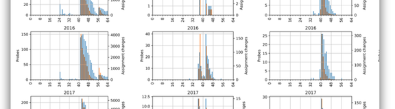
In prior work, we've studied IPv4 allocation patterns in domestic ISPs. Time has passed, and IPv6 adoption has continued, so in this article we review our current observations on IPv4 and IPv6 assignment practices.
ISPs assign parts of their address space to users and subscribers. These assignments are typically not static. Often in a domestic network, a subscriber's CPE will negotiate a lease on an individual IPv4 address or an IPv6 subnet via a DHCP or RADIUS exchange.
How long do these assignments last for? In IPv4 it's common for users to receive an individual address, but in IPv6 entire subnets are delegated. How large are those subnets? There are BCP recommendations that steer networks towards particular subnet sizes, but networks are free to select subnet sizes according to their own addressing plans. Can we observe the size of the subnets that are assigned from measurement data?
The duration and size of assignments has various implications:
- Reputation : If you're a content or service provider who occasionally has to block abusive behaviour from the network, what is the potential collateral damage?
- Geolocation : If you generate geo datapacks, how reliable do your customers consider them? If you rely on geo datapacks, how stale might they be?
- Measurement : If you're a network researcher attempting to scan active portions of the IPv6 address space, how much of an ISP's space is in use and how is it subdivided?
Ongoing Measurements
RIPE Atlas runs, among other built-in measurements , echo measurements. These are HTTP requests from probes to servers operated by the RIPE NCC, the response to which contains the IP address observed by the server. These measurements therefore report the publicly visible address from any probe, whether it's a globally visible IPv6 address or the shared address on an IPv4 CGNAT. The measurements run every 15 minutes, giving us a dataset of IPv4 and IPv6 address changes over many years. Given we know which probe performs each echo request, we have data on when each probe's IPv4 and IPv6 addresses change, and whether or not those changes are synchronous.
The RIPE Atlas platform has extensive coverage in some networks, but not all networks. In addition to the RIPE Atlas dataset, we make use of data from a large CDN. This dataset contains address associations purposefully constructed from browser sessions where a resource has been requested over both IPv4 and an IPv6. The IPv4 addresses are masked to /24s and the IPv6 addresses are masked to /64s. This dataset gives us a bound on when two addresses appear to have been assigned to the same user. Utilising five months of data, we have over 30 billion address associations in this dataset, allowing us to cover more networks than with the RIPE Atlas dataset alone.
We make use of this larger dataset in the full paper (linked at the bottom of this article). In this article, we'll look more closely at the RIPE Atlas dataset and related data in the RIPE database.
Address Lifetimes
The long-term scarcity of IPv4 addresses and intermittent connectivity (e.g., dial-up connections) led networks towards leasing IPv4 addresses from shared pools. Leases expire, and networks differ on how sticky addresses are or how long a lease should last. IPv6 deployments have taken place in a different era, where many more connections are likely to be always-on, and the scarcity argument is removed.
In Figure 1, we show the difference between address assignment lifetimes in IPv4 and IPv6.
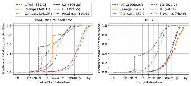
Figure 1: Frequency of assignment durations in IPv4 and IPv6 environments. Strong vertical lines indicate Y% of time is spent with the durations on the X axis.
To understand the above plots, consider Deutsche Telekom (DTAG). On the left, we show IPv4-only probes, and on the right IPv6 (largely dual-stacked) probes. The vertical lines indicate common address durations; IPv4-only hosts appear to spend just under 60% of their time with 1 day assignments (or shorter), while the IPv6 durations are typically longer than 1 day (over 60% of their assignments persist longer than 1 day). In the paper, we additionally show that IPv4 lifetimes for dual-stacked hosts tend to have longer lifetimes than for single-stacked IPv4 networks, if not quite as long as IPv6 prefix delegations.
We see a clear divergence between how long IPv4 and IPv6 assignments persist in these networks. Indeed, we observe that IPv6 assignments tend to persist longer in most networks. This distinction between IPv4 and IPv6 may be important to consider when determining how long to block abusive behaviour or how stale to consider geo data, for example.
Delegated Prefixes
ISPs delegate an IPv6 prefix to each subscriber, but the size of that delegated prefix is decided by the ISP. A natural lower limit on the size of the delegated prefix is /64, though best practice suggests that larger subnets should be defined . ISPs are not consistent in how they delegate prefixes, nor do they have any need to be! Some ISPs describe their address architecture for subscribers publicly, and some do not. What can we glean instead from measurement data?
We take a simple approach to identifying the size of the prefixes assigned to a network: count the zero bits prior to the /64 boundary. The notion of prefix delegation entitles CPE or network operators to subdivide their network as they see fit, but the intuition is that many networks choose to keep things simple and their CPE uses the zeroth /64 in the delegated prefix. Taking this simple approach, we are able to identify patterns per-network in Figure 2, based on those runs of zeroes in the addresses.
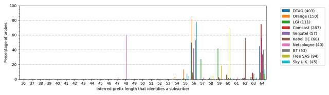
Figure 2: Inferred delegated prefix lengths from RIPE Atlas data. Y% of probes in a given network appear to have a delegated prefix of length X. The value in parenthesis on the right is the number of probes in the dataset for that ISP.
Across these networks, where we have many probes and many address changes to inspect, we observe some distinct signals:
- Many, but not all, networks appear to be assigning /56s to customers
- Comcast, which typically appears to assign a /64
- Kabel, which typically assigns a /62
- Free, which typically assigns a /60
- Deutsche Telekom has two spikes, at /56 and /64, and this appears to be driven by a distinction whereby a /56 is issued and some CPE models cycle through multiple /64s in that space .
- Netcologne, which typically assigns a /48.
So using this data alone, we can already observe that there's a wide variation in how much address space each ISP is willing to give their customers.
Assignment Size Data in the RIPE Database
It is useful for anybody outside of a network to know the size of the prefixes assigned to customers. Some operators publish their addressing practices on the web, but one additional means to share information -- which we don't touch on in the paper -- is via the RIPE database (a.k.a., whois).
An LIR -- in our case, domestic ISPs -- with IPv6 space can subdivide that space and ultimately assign parts of it to end users. LIRs are obligated to describe their IPv6 assignments in the database . An overview of how to document IPv6 assignments in the RIPE database is available here . In short, inet6num objects may describe a specific assignment to a customer, or may describe a pool of space from which assignments are made to customers.
The latter category of objects have the status AGGREGATED-BY-LIR , and inet6num objects with this status must include an assignment-size parameter. This parameter states the block size that end users should be uniformly assigned from within the address space described by the object.
There are 44 thousand inet6num objects with an assignment-size attribute. The values registered typically align with what you may expect: the most common listed assignment-size is /56 (in over 81% of the inet6num objects), then /64 (11%), then /48 (6%). The remaining values are fewer than 2% of the registered assignment-sizes, including 244 /128s; it'd be interesting to know how people are using network prefixes longer than /64!
The data in the database may be reliable as a means to verify our measurements above. In order to align these two datasets, in Figure 3 we've taken the same set of probes and the /64s that were observed from those probes as we used for Figure 2. But instead of inferring the delegated prefix from the bits we saw active, we search the RIPE database for the covering inet6num object, and look for an assignment-size value in that object.
The results look as follows:
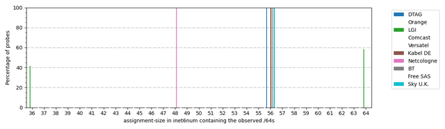
Figure 3: Registered assignment-size values in the RIPE Database for the prefixes assigned to probes. Percentage of probes refers to percentage when assignment-size information exists.
Note that some networks aren't registering this field (or they exist out of the RIPE region), so for those networks we have nothing to compare. We have data for Deutsche Telekom, Liberty Global, Kabel DE, Free, Netcologne, BT, and Sky.
We have a few observations to make in the above:
- There's a clear intent across these networks to select /56s for delegation to subscribers, which is good. That both fits with BCOP-690 and with the patterns measured in Figure 2.
- Deutsche Telekom clearly issues a /56, according to the database. This is a clear distinction to the split in Figure 2 between the identified /56s and /64s, typically a distinction in CPE behaviour. Our heuristic was deliberately simple, and with a little more work we should be able to detect cycling within a common subnet.
- Netcologne (AS8422) provides a /48 to all probes that we have address change data for in Figure 2, and indeed the database agrees in Figure 3. A full 16-bits of address space for their customers!
- Liberty Global (LGI) has operations across many countries and for LGI prefixes with matching assignment-size data, we see a split between /36s and /64s. The /36 value comes from Cablecom in Switzerland , though in Figure 2 we observed nothing close to a /36 and so that feels like bad or stale data in the database. The /64 value comes from T-Mobile Austria , and so likely represents assignments to mobile subscribers. Figure 2 reveals probes that appear to have been assigned a /56, so we presumably are simply identifying parts of LGI that aren't lodging this data in the database.
We'd love to be able to get more of the networks we've studied specifying this information publicly, and the RIPE database seems a trustworthy means to enable this. The partial data we have above seems like it'd be useful for the applications outlined at the start of this article.
Implications
Understanding domestic stability of the IP address space -- be it temporal or spatial -- is useful for various applications. The key here is that assumptions from the IPv4 world may not carry to the IPv6 world.
But this might not be such a bad thing. For example, if a service is typically willing to drop traffic from a single IPv4 address for 24 hours to dampen some malicious behaviour, that same heuristic applied to IPv6 is likely to be too short rather than too long. That's a reasonable position as an operator: the collateral damage is lessened.
Similarly, a block on a single /64 is likely to be too narrow: a knowledgable attacker could select a subnet elsewhere within their /56, and then you may have a game of whack-a-mole on your hands. But since a /64 is an atomic unit of IPv6 networks, it's also likely not to block more than one household in the first attempt.
More per-network knowledge is useful for everybody, and it's likely to be in the community's best interests if networks publicise more about their addressing plans.
There's much more detail in the full paper which we presented at CoNEXT 2020 , so go check it out! We have additional graphs available on this web page . And if you prefer video form, the short (12.5 minute) video for our paper is here:
More from this author
You may also like.

IPv6 Adoption in 2021

Improvements to the RIPE Atlas Datasets on Google BigQuery

Reviewing RIPE Atlas Software Probes
About the author.
Stephen is a principal engineer in the Office of the CTO at Fastly, where he spends his time trying to figure out what the Internet is. He obtained his PhD in Internet routing scalability from the University of Glasgow in 2012.
Comments are disabled on articles published more than a year ago. If you'd like to inform us of any issues, please reach out to us via the contact form here .
- Explore Categories:
- Network Operations
- Measurements and Statistics
- Internet Governance
- Technology and Innovation
- Community and Events
- Configure the Way RRAS Assigns IP Addresses to VPN Clients
You can use a DHCP server to assign IP addresses to VPN clients or you can configure an RRAS server to use a static pool of IP addresses for allocation to TCP/IP-based remote access and demand-dial connections. For more information, see RRAS and DHCP (https://go.microsoft.com/fwlink/?linkid=140605).
Membership in the local Administrators group, or equivalent, is the minimum required to complete this procedure.
Open the RRAS MMC Snap-in .
Right-click the RRAS server name, and then click Properties . If you are using Server Manager, right-click Routing and Remote Access , and then click Properties .
On the Properties page, click the IPv4 tab.
Under IPv4 address assignment , click Static address pool .
Click Add .
In Start IP address , type a starting IP address.
Type either an ending IP address for the range in End IP address , or type the number of IP addresses in the range in Number of addresses , and then click OK .
Click OK , and then repeat steps 5 through 7 for as many ranges as you need to add.
Right-click the server name for which you want to create a static IP address pool, and then click Properties . If you are using Server Manager, right-click Routing and Remote Access , and then click Properties .
Under IPv4 address assignment , click Dynamic Host Configuration Protocol (DHCP) .
Click OK to save your changes.
Additional considerations
- If the static IP address pool consists of ranges of IP addresses that are for a separate subnet, then you need to either enable an IP routing protocol on the remote access server computer or add static IP routes consisting of the {IP Address, Mask} of each range to the routers of the intranet. If the routes are not added, then remote access clients cannot receive traffic from resources on the intranet.
- If the DHCP server is on the same subnet as the RRAS server, then you do not have to configure the DHCP relay agent. RRAS can find DHCP servers on the same subnet by using broadcast network packets.
Additional references
- RRAS and DHCP (https://go.microsoft.com/fwlink/?linkid=140605)
- Configuring RRAS
Table Of Contents
- Common Remote Access Scenarios
- Common Routing Scenarios
- Requirements for Installing RRAS as a VPN Server
- Dial-Up Networking
- Permissions for Remote Access Users
- IP Address Assignment
- Remote Access Authentication Protocols
- Network Policies
- Checklist: Installing and Configuring an RRAS VPN Server
- Checklist: Installing and Configuring an RRAS Router
- Checklist: Configuring Remote Access Behind a NAT-Enabled Router
- Checklist: Connecting Remote Sites
- Install RRAS
- Open the RRAS MMC Snap-in
- Configure a Dial-Up Remote Access Server
- Configure Logging Levels for RRAS
- Configure Network Access Protection Enforcement for VPN
- Configure Ports for Remote Access
- Configure RRAS with a Computer Authentication Certificate
- Configure the IPv4 DHCP Relay Agent
- Configure the IPv6 DHCP Relay Agent
- Configure TCP/IP on the RRAS Server
- Create a Demand-Dial Interface
- Create a Static Route
- Enable and Configure NAT
- Enable and Configure RIP
- Enable IPv6 Remote Access
- Enable RRAS as a LAN and WAN Router
- Enable RRAS as a VPN Server
- Enable RRAS as a VPN Server and a NAT Router
- Remove RRAS from a Server
- View Information in RRAS
- Troubleshooting RRAS
- Resources for RRAS
- RRAS Setup Wizard - Configuration Page
- RRAS Setup Wizard - Remote Access
- RRAS Setup Wizard - Remote Access - Dial-up - Network Selection
- RRAS Setup Wizard - Remote Access - IP Address Assignment
- RRAS Setup Wizard - Remote Access - Managing Multiple Remote Access Servers
- RRAS Setup Wizard - Remote Access - VPN Connection Page
- RRAS Setup Wizard - Custom Configuration
- RRAS Setup Wizard - Address Range Assignment
- RRAS Setup Wizard - NAT Internet Connection Page
- RRAS Setup Wizard - Demand-Dial Connections Page
- RRAS Setup Wizard - Closing Page
- RRAS Server Properties Page - General Tab
- RRAS Server Properties Page - Security Tab
- RRAS Server Properties Page - IPv4 Tab
- RRAS Server Properties Page - IPv6 Tab
- RRAS Server Properties Page - IKEv2 Tab
- RRAS Server Properties Page - PPP Tab
- RRAS Server Properties Page - Logging Tab
- Network Interfaces - Demand-dial - Properties Page - General Tab
- Network Interfaces - Demand-dial - Properties Page - Options Tab
- Network Interfaces - Demand-dial - Properties Page - Security Tab
- Network Interfaces - Demand-dial - Properties Page - Networking Tab
- Network Interfaces - Demand-dial - Set IP Demand-dial Filters
- Network Interfaces - Demand-dial - Set IPv6 Demand-dial Filters
- Remote Access Clients
- Remote Access Logging & Policies
- IPv4 - General - Properties Page - Logging Tab
- IPv4 - General - Properties Page - Preference Levels Tab
- IPv4 - General - Properties Page - Multicast Scopes Tab
- IPv4 - General - Interface - Properties Page - General Tab
- IPv4 - General - Interface - Properties Page - Multicast Boundaries Tab
- IPv4 - General - Interface - Properties Page - Multicast Heartbeat Tab
- IPv4 - Static Routes - New IPv4 Static Route
- IPv4 - DHCP Relay Agent - Properties Page
- IPv4 - DHCP Relay Agent - Interface - Properties Page
- IPv4 - IGMP - Properties Page
- IPv4 - IGMP - Interface - Properties Page - General Tab
- IPv4 - IGMP - Interface - Properties Page - Router Tab
- IPv4 - NAT - Properties Page - General Tab
- IPv4 - NAT - Properties Page - Translation Tab
- IPv4 - NAT - Properties Page - Address Assignment Tab
- IPv4 - NAT - Properties Page - Name Resolution Tab
- IPv4 - NAT - Interface - Properties Page - NAT Tab
- IPv4 - NAT - Interface - Properties Page - Address Pool Tab
- IPv4 - NAT - Interface - Properties Page - Services and Ports Tab
- IPv4 - RIP - Properties Page - General Tab
- IPv4 - RIP - Properties Page - Security Tab
- IPv4 - RIP - Interface - Properties Page - General Tab
- IPv4 - RIP - Interface - Properties Page - Security Tab
- IPv4 - RIP - Interface - Properties Page - Neighbors Tab
- IPv4 - RIP - Interface - Properties Page - Advanced Tab
- IPv6 - General - Properties Page
- IPv6 - General - Interface - Properties Page
- IPv6 - Static Routes - New IPv6 Static Route
- IPv6 - DHCPv6 Relay Agent - Properties Page - General Tab
- IPv6 - DHCPv6 Relay Agent - Properties Page - Servers Tab
- IPv6 - DHCPv6 Relay Agent - Interface - Properties Page
- Demand-Dial Interface Wizard - Connection Type Page
- Demand-Dial Interface Wizard - VPN Type Page
- Demand-Dial Interface Wizard - Protocols and Security Page
- Dialog Box - Add Address Pool
- Dialog Box - Add or Edit IPv4 Filter
- Dialog Box - Add or Edit IPv6 Filter
- Dialog Box - Add or Edit Service
- Dialog Box - Add RADIUS Accounting Server
- Dialog Box - Add RADIUS Authentication Server
- Dialog Box - Add Reservation
- Dialog Box - Authentication Methods
- Dialog Box - Configure Device
- Dialog Box - Inbound and Outbound Filters
- Dialog Box - Port Status
- Dialog Box - PPP Settings
- Dialog Box - Reserve Addresses
- Dialog Box - Smart Card or Other Certificate Properties
- Dialog Box - VPN Advanced Properties
- Support Forum
- Customer Service
- FortiClient
- FortiAnalyzer
- FortiAuthenticator
- FortiBridge
- FortiCarrier
- FortiConnect
- FortiConverter
- FortiDeceptor
- FortiDevSec
- FortiDirector
- FortiExtender
- FortiGate Cloud
- FortiHypervisor
- FortiInsight
- FortiIsolator
- FortiManager
- FortiMonitor
- FortiNDR (on-premise)
- FortiNDRCloud
- FortiPortal
- FortiRecorder
- FortiSandbox
- FortiSwitch
- FortiTester
- Wireless Controller
- RMA Information and Announcements
- FortiCloud Products
- 4D Documents
- Engage Services
- The EPSP Platform
- The ETSP Platform
- Discussions
- Technical Learning
- Knowledge Base
- Idea Exchange
- Announcements
- Fortinet Community
- Technical Tip: IPv4 address exhaustion in ike mode...
- Subscribe to RSS Feed
- Mark as New
- Mark as Read
- Printer Friendly Page
- Report Inappropriate Content

Technical Tip: IPv4 address exhaustion in ike mode-cfg
- FortiGate v5.6
- FortiGate v6.0
- FortiGate v6.2
- FortiGate v6.4
- FortiGate v7.0
- FortiGate v7.2
- FortiGate v7.4

The Fortinet Security Fabric brings together the concepts of convergence and consolidation to provide comprehensive cybersecurity protection for all users, devices, and applications and across all network edges.
- Threat Research
- FortiGuard Labs
- Threat Briefs
- Getting Started Resources
- Security Fabric
- Certifications
- Industry Awards
- Social Responsibility
- News Releases
- News Articles
Copyright 2024 Fortinet, Inc. All Rights Reserved.
- Terms of Service
- Privacy Policy
- Cookie Settings
- ns-3
- Models
- 16. Internet Models (IP, TCP, Routing, UDP)
16.2. IPv4 
This chapter describes the ns-3 IPv4 address assignment and basic components tracking.
16.2.1. IPv4 addresses assignment 
In order to use IPv4 on a network, the first thing to do is assigning IPv4 addresses.
Any IPv4-enabled ns-3 node will have at least one NetDevice: the ns3::LoopbackNetDevice . The loopback device address is 127.0.0.1 . All the other NetDevices will have one (or more) IPv4 addresses.
Note that, as today, ns-3 does not have a NAT module, and it does not follows the rules about filtering private addresses ( RFC 1918 ): 10.0.0.0/8, 172.16.0.0/12, and 192.168.0.0/16. These addresses are routed as any other address. This behaviour could change in the future.
IPv4 global addresses can be:
- manually assigned
- assigned though DHCP
ns-3 can use both methods, and it’s quite important to understand the implications of both.
16.2.1.1. Manually assigned IPv4 addresses 
This is probably the easiest and most used method. As an example:
This method will add two global IPv4 addresses to the nodes.
Note that the addresses are assigned in sequence. As a consequence, the first Node / NetDevice will have “192.168.1.1”, the second “192.168.1.2” and so on.
It is possible to repeat the above to assign more than one address to a node. However, due to the Ipv4AddressHelper singleton nature, one should first assign all the addresses of a network, then change the network base ( SetBase ), then do a new assignment.
Alternatively, it is possible to assign a specific address to a node:
16.2.1.2. DHCP assigned IPv4 addresses 
DHCP is available in the internet-apps module. In order to use DHCP you have to have a DhcpServer application in a node (the DHC server node) and a DhcpClient application in each of the nodes. Note that it not necessary that all the nodes in a subnet use DHCP. Some nodes can have static addresses.
All the DHCP setup is performed though the DhcpHelper class. A complete example is in src/internet-apps/examples/dhcp-example.cc .
Further info about the DHCP functionalities can be found in the internet-apps model documentation.
16.2.2. Tracing in the IPv4 Stack 
The internet stack provides a number of trace sources in its various protocol implementations. These trace sources can be hooked using your own custom trace code, or you can use our helper functions in some cases to arrange for tracing to be enabled.
16.2.2.1. Tracing in ARP 
ARP provides two trace hooks, one in the cache, and one in the layer three protocol. The trace accessor in the cache is given the name “Drop.” When a packet is transmitted over an interface that requires ARP, it is first queued for transmission in the ARP cache until the required MAC address is resolved. There are a number of retries that may be done trying to get the address, and if the maximum retry count is exceeded the packet in question is dropped by ARP. The single trace hook in the ARP cache is called,
- If an outbound packet is placed in the ARP cache pending address resolution and no resolution can be made within the maximum retry count, the outbound packet is dropped and this trace is fired;
A second trace hook lives in the ARP L3 protocol (also named “Drop”) and may be called for a number of reasons.
- If an ARP reply is received for an entry that is not waiting for a reply, the ARP reply packet is dropped and this trace is fired;
- If an ARP reply is received for a non-existent entry, the ARP reply packet is dropped and this trace is fired;
- If an ARP cache entry is in the DEAD state (has timed out) and an ARP reply packet is received, the reply packet is dropped and this trace is fired.
- Each ARP cache entry has a queue of pending packets. If the size of the queue is exceeded, the outbound packet is dropped and this trace is fired.
16.2.2.2. Tracing in IPv4 
The IPv4 layer three protocol provides three trace hooks. These are the “Tx” (ns3::Ipv4L3Protocol::m_txTrace), “Rx” (ns3::Ipv4L3Protocol::m_rxTrace) and “Drop” (ns3::Ipv4L3Protocol::m_dropTrace) trace sources.
The “Tx” trace is fired in a number of situations, all of which indicate that a given packet is about to be sent down to a given ns3::Ipv4Interface.
- In the case of a packet destined for the broadcast address, the Ipv4InterfaceList is iterated and for every interface that is up and can fragment the packet or has a large enough MTU to transmit the packet, the trace is hit. See ns3::Ipv4L3Protocol::Send.
- In the case of a packet that needs routing, the “Tx” trace may be fired just before a packet is sent to the interface appropriate to the default gateway. See ns3::Ipv4L3Protocol::SendRealOut.
- Also in the case of a packet that needs routing, the “Tx” trace may be fired just before a packet is sent to the outgoing interface appropriate to the discovered route. See ns3::Ipv4L3Protocol::SendRealOut.
The “Rx” trace is fired when a packet is passed from the device up to the ns3::Ipv4L3Protocol::Receive function.
- In the receive function, the Ipv4InterfaceList is iterated, and if the Ipv4Interface corresponding to the receiving device is found to be in the UP state, the trace is fired.
The “Drop” trace is fired in any case where the packet is dropped (in both the transmit and receive paths).
- In the ns3::Ipv4Interface::Receive function, the packet is dropped and the drop trace is hit if the interface corresponding to the receiving device is in the DOWN state.
- Also in the ns3::Ipv4Interface::Receive function, the packet is dropped and the drop trace is hit if the checksum is found to be bad.
- In ns3::Ipv4L3Protocol::Send, an outgoing packet bound for the broadcast address is dropped and the “Drop” trace is fired if the “don’t fragment” bit is set and fragmentation is available and required.
- Also in ns3::Ipv4L3Protocol::Send, an outgoing packet destined for the broadcast address is dropped and the “Drop” trace is hit if fragmentation is not available and is required (MTU < packet size).
- In the case of a broadcast address, an outgoing packet is cloned for each outgoing interface. If any of the interfaces is in the DOWN state, the “Drop” trace event fires with a reference to the copied packet.
- In the case of a packet requiring a route, an outgoing packet is dropped and the “Drop” trace event fires if no route to the remote host is found.
- In ns3::Ipv4L3Protocol::SendRealOut, an outgoing packet being routed is dropped and the “Drop” trace is fired if the “don’t fragment” bit is set and fragmentation is available and required.
- Also in ns3::Ipv4L3Protocol::SendRealOut, an outgoing packet being routed is dropped and the “Drop” trace is hit if fragmentation is not available and is required (MTU < packet size).
- An outgoing packet being routed is dropped and the “Drop” trace event fires if the required Ipv4Interface is in the DOWN state.
- If a packet is being forwarded, and the TTL is exceeded (see ns3::Ipv4L3Protocol::DoForward), the packet is dropped and the “Drop” trace event is fired.
16.2.3. Explicit Congestion Notification (ECN) bits 
- In IPv4, ECN bits are the last 2 bits in TOS field and occupy 14th and 15th bits in the header.
- The IPv4 header class defines an EcnType enum with all four ECN codepoints (ECN_NotECT, ECN_ECT1, ECN_ECT0, ECN_CE) mentioned in RFC 3168, and also a setter and getter method to handle ECN values in the TOS field.
16.2.4. Ipv4QueueDiscItem 
The traffic control sublayer in ns-3 handles objects of class QueueDiscItem which are used to hold an ns3::Packet and an ns3::Header. This is done to facilitate the marking of packets for Explicit Congestion Notification. The Mark () method is implemented in Ipv4QueueDiscItem. It returns true if marking the packet is successful, i.e., it successfully sets the CE bit in the IPv4 header. The Mark () method will return false, however, if the IPv4 header indicates the ECN_NotECT codepoint.
16.2.5. RFC 6621 duplicate packet detection 
To support mesh network protocols over broadcast-capable networks (e.g. Wi-Fi), it is useful to have support for duplicate packet detection and filtering, since nodes in a network may receive multiple copies of flooded multicast packets arriving on different paths. The Ipv4L3Protocol model in ns-3 has a model for hash-based duplicate packet detection (DPD) based on Section 6.2.2 of ( RFC 6621 ). The model, disabled by default, must be enabled by setting EnableRFC6621 to true. A second attribute, DuplicateExpire , sets the expiration delay for erasing the cache entry of a packet in the duplicate cache; the delay value defaults to 1ms.
16.2.6. NeighborCache 
NeighborCacheHelper provides a way to generate ARP cache automatically. It generates needed ARP cache before simulation start to avoid the delay and message overhead of address resolution in simulations that are focused on other performance aspects. The state of entries which are generated by NeighborCacheHelper is STATIC_AUTOGENERATED , which is similar to PERMANENT , but they are not manually added or removed by user, they will be managed by NeighborCacheHelper when user need pre-generate cache. When user is generating neighbor caches globally, neighbor caches will update dynamically when IPv4 addresses are removed or added; when user is generating neighbor caches partially, NeighborCacheHelper will take care of address removal, for adding address user may rerun a reduced-scope PopulateNeighbor() again to pick up the new IP address or manually add an entry to keep the neighbor cache up-to-date, the reason is that: when PopulateNeighborCache() has previously been run with a scope less than global, the code does not know whether it was previously run with a scope of Channel, NetDeviceContainer, or Ip interface container. The source code for NeighborCache is located in src/internet/helper/neighbor-cache-helper A complete example is in src/internet/examples/neighbor-cache-example.cc .
16.2.6.1. Usage 
The typical usages are:
- Populate neighbor ARP caches for a given channel:
- Populate neighbor ARP caches for devices in a given NetDeviceContainer:
- Populate neighbor ARP caches for a given Ipv4InterfaceContainer:
Table of Contents
- 16.2.1.1. Manually assigned IPv4 addresses
- 16.2.1.2. DHCP assigned IPv4 addresses
- 16.2.2.1. Tracing in ARP
- 16.2.2.2. Tracing in IPv4
- 16.2.3. Explicit Congestion Notification (ECN) bits
- 16.2.4. Ipv4QueueDiscItem
- 16.2.5. RFC 6621 duplicate packet detection
- 16.2.6.1. Usage
Previous topic
16.1. Internet Stack
- Show Source
Quick search
Address assignment
Overview of the address assignment, and details on the supported local (ODSA) and AAA-based address assignment.
Overview of address assignment
For sessions that require direct connectivity to a Layer 3 network, the MAG-c supports the following address assignment options:
- local address assignment via ODSA
- local static address assignment via authentication database
AAA-based address assignment
- non-provisioned address assignment
Additionally, the MAG-c allocates corresponding prefixes (micro-nets) for the BNG-UP , to allow a BNG-UP device to send aggregate routes without announcing the per-session routes. For IPv4, the MAG-c assigns a dedicated gateway address per prefix. It is possible to select different address allocation methods for different address types of the same session. For example, IPv4 can use AAA-based address assignment while IPv6 PD can use a local pool. However, all allocation methods should be known after session authentication.
After session authentication, an address is allocated based on the local address assignment or the AAA-based address assignment. Addresses are always set up on the BNG-UP as soon as they are allocated, independent of whether they are already signaled in associated assignment protocols such as DHCP or IPCP.
ODSA and local address assignment
ODSA can be used to assign a local address, to assign an aggregate prefix per BNG-UP , and to derive the default gateway.
On demand subnet allocation (ODSA) is a dedicated CUPS address assignment system.
ODSA is a dedicated CUPS address assignment system that can automatically split a common subnet into smaller subnets (micro-nets). The micro-nets are automatically installed on the associated BNG-UP . The BNG-UP announces the micro-nets in routing. ODSA can either assign an address itself (local address assignment), or work in combination with external address assignment systems (for example, AAA-based).
ODSA pools are configured on a per network-realm basis. A network realm represents a single IP routing context and maps to an IP service on the BNG-UP (for example, to a VPRN). ODSA guarantees that there is no overlap between addresses within one network realm.
The main function of ODSA is to assign subnets to an allocation context. The default allocation context is a single BNG-UP . In resilient environments, the allocation context is a single fate-sharing group (FSG). Each ODSA pool consists of one or more prefixes and is either configured in dedicated mode or with a target micro-net length.
In dedicated mode, a prefix is assigned directly to an allocation context. It is not divided into smaller micro-nets.
With a target micro-net length, all prefixes are divided into smaller, equally sized, micro-nets. Those smaller micro-nets are assigned to an allocation context.
In case of DHCPv6 prefix delegation, you can allocate a variable prefix length per session and a variable micro-net size.
The following example shows the configuration of an ODSA pool with a target micro-net length.
A subnet (either micro-net or dedicated prefix) can be assigned to only one context. When the first address of a subnet is assigned to a session, the subnet is assigned to the context of the session (for example, to a BNG-UP ). To guarantee that the full subnet can always be announced in routing without introducing routing conflicts, the following applies.
- The subnet is only unlinked from the context after the last address of the subnet is released.
- While a subnet is linked to a context, no address of the subnet can be assigned to another context, even if ODSA does not do the address assignment for the other context.
Variable prefix length and micro-net length
For DHCPv6 prefix delegation, you can allocate a variable prefix length per session and a variable micro-net size.
- Configure a minimum and maximum prefix length for ODSA using the variable command in the config>mobile>pdn>laa>network-realm>pool>ipv6>pd>delegated-prefix context.
- Provision different prefix lengths per session during session setup.
ODSA allocates a micro-net per prefix length. For example, consider the following sequence of session setups, all within the same ODSA pool and BNG-UP .
- Session 1 with prefix length 56 leads to the allocation of micro-net A.
- Session 2 with prefix length 64 leads to the allocation of a new micro-net B.
- Session 3 with prefix length 64 re-uses micro-net B.
- Session 4 with prefix length 56 re-uses micro-net A.
- Session 5 with prefix length 60 leads to the allocation of a new micro-net C.
When only one micro-net length is configured, this leads to unequally loaded micro-nets. For example, for a micro-net length of 52 with variable prefix lengths 64 and 56, each micro-net can hold up to 4096 /64 prefixes, but only 16 /56 prefixes. When the variable prefix length range is big, this is not wanted. For example, an allowed prefix length range of 48 to 64 requires at least a /44 micro-net, which can cover up to 1048576 /64 prefixes.
- For a variable micro-net length between 42 and 50, and a variable prefix-length between 56 and 64, the system allocates a /50 micro-net for a /64 prefix, a /42 micro-net for a /56 prefix, and a /46 micro-net for a /60 prefix. Each micro-net holds up to 16384 prefixes, independent of its length.
- For a variable micro-net length between 48 and 50, and a variable prefix-length between 54 and 64, the system allocates a /50 micro-net for a /64 prefix which holds 16384 prefixes, and a /48 micro-net for a /54 prefix which holds 64 addresses.
When using variable micro-net lengths, the number of free micro-nets is not deterministic. A micro-net with a small length uses a bigger chunk of the pool than a micro-net with a large length. Therefore, the threshold mechanism, configured using the minimum-free command in the config>mobile>pdn>laa>network-realm>pool context, is adapted as follows.
- When the minimum-free configuration is an absolute value, the threshold takes into account the biggest micro-net size. A log event is generated as soon as there is not enough space in the pool to allocate the configured amount of micro-nets with the minimum length.
- When the minimum-free configuration is a percentage, the threshold takes into account the smallest micro-net size. A log event is generated as soon as there is not enough space in the pool to allocate the configured percentage of micro-nets with the maximum length.
Local address assignment
ODSA can act as a stand-alone subnet allocation mechanism for BNG-UP devices, but it can also assign addresses to individual sessions, without the need for additional configuration.
To allocate an address for a session, ODSA performs the following checks.
- Are there subnets already linked to the allocation context of the session?
- Do any of the linked subnets have available addresses?
If the answer to both questions is yes, an address from any of the linked subnets is allocated to the session.
If the answer to one of the questions is no, a new address is allocated from any subnet that is not yet linked to an allocation context. The subnet is automatically linked to the allocation context of the session. If no subnets are available, the address allocation fails.
- config>mobile>pdn>laa>network-realm>pool>ipv4>prefix
- slaac>prefix
- na>prefix
- pd>prefix
Excluded address ranges can be assigned with other allocation methods (for example, via AAA). In case of IPv6, excluded address ranges are not used for default gateway selection.
Existing address allocations from the prefix remain allocated until the corresponding sessions are terminated.
Local address assignment can be combined with AAA-based address assignment for different address types. For example, IPv4 and IPv6 PD can use local address assignment while IPv6 NA can use AAA-based assignment.
AAA services can provide an address during authentication. The MAG-c marks the AAA-based address as in use in the ODSA pools and allocates the micro-net to the corresponding context (for example, the BNG-UP ). In the case of IPv4, the default gateway is assigned using ODSA.
An AAA-based address can fall within an exclude-addresses range.
Setup of the new session fails in situations such as the following:
- the address is already allocated to another session
- the corresponding micro-net is allocated to a context that does not match the context of the session
The prefix pool on which ODSA operates can be used in the following ways.
- If the AAA service provisions both an address pool and an explicit IP address for the same address type (for example, IPv4 or IPv6 PD), ODSA uses the explicit IP address for assignment and the pool for marking the address and allocating BNG-UP prefixes and IPv4 gateway addresses.
- In the absence of an AAA pool, a pool can be provisioned using the unmanaged command in the config>mobile>profile>adb>entry>address-assignment context.
- In the absence of any pool during authentication, a pool can be provisioned per APN using the unmanaged command in the config>mobile>pdn>apn>address-assignment-defaults context.
When no dedicated pools are available, ODSA assigns micro-nets to a context. It is important that the AAA service is aware of the micro-net sizes and that addresses are allocated per context within the scope of a micro-net.
For example, the prefix 192.168.0.0/16 is available, to which addresses are allocated per BNG-UP in the AAA. For example, all sessions of BNG-UP 1 fall within 192.168.1.0/24 and all sessions of BNG-UP 2 fall within 192.168.2.0/24. In this case, it is not necessary to provision these per- BNG-UP prefixes on the MAG-c . The MAG-c has provisioned a non-dedicated pool with prefix 192.168.0.0/16 and micro-net length 24 and automatically derives the /24 prefixes based on the AAA-based addresses.
The following requirements apply when using ODSA pools for a mix of AAA-based addresses and locally assigned addresses.
- The AAA-based addresses must fall within the configured exclude-addresses ranges to avoid conflicts with local assigned addresses.
- If a pool is not dedicated to a specific context (for example, the BNG-UP ), the exclude-addresses ranges should align with a micro-net size. This is required to avoid the case where a locally-assigned address allocates the corresponding micro-net to a different context.
Because of the complexity of the requirements, Nokia recommends to have a non-dedicated pool for AAA-based address assignment and a separate non-dedicated pool for local address assignment.
The MAG-c supports AAA provisioned framed routes for sessions with ip-anti-spoof disabled (set to false ); for example, using the Framed-Route and Framed-IPv6-Route RADIUS attributes. The MAG-c installs these routes on the BNG-UP using the PFCP protocol. The MAG-c does not check these routes for overlap with other framed routes or session allocated addresses.
Non-provisioned address assignment
Configuration of the support for non-provisioned addresses in the ADB allows an external entity to assign the session address.
When an external entity managed by a third party (for example, a RADIUS server) assigns the session address, the operator is not aware of the subnet/prefix where the address is assigned from. Therefore, the operator cannot provision this subnet/prefix on the BNG system.
- After ADB lookup, non-provisioned addresses are supported for the new session.
- The external source assigns an address of a configured address type.
- The address is not within any subnet/prefix of the configured ODSA pool.
To support unmatching addresses of specified address types, use the unmatching-prefix allow command in the config>mobile>profile>adb>entry>address-assignment context.
The MAG-c cannot send the subnet/prefix information to the BNG-UP because the subnet/prefix for the unmatching address is not provisioned on the BNG system. Therefore, the BNG-UP has /32 or /128 routes for each unmatching address, or the exact prefix route for an IPv6 SLAAC delegated prefix.
The following applies to an unmatching address via DHCPv4.
The MAG-c automatically generates a default router address and returns it in the DHCP reply. This auto-generated default router address is not passed to the BNG-UP , so the BNG-UP uses the ARP proxy to answer the client’s ARP request for the default router address.
To generate the default router address, the host address part of the assigned address is set to one, or to two if the host address part already equals one. The following examples illustrate the generation of the default router address.
- The assigned address is 172.16.3.139 and the netmask is /28, so the host bits are the last 4 bits. 139 equals the binary number 0b10001011. The value of the host bits does not equal 1. When setting the value of the last 4 bits to 1, it becomes 0b10000001 or 129. The default router address is 172.16.3.129.
- The assigned address is 172.16.3.129 and the netmask is /28, so the host bits are the last 4 bits. 129 equals the binary number 0b10000001. The value of the host bits already equals 1. When setting the value of the last 4 bits to 2, it becomes 0b10000010 or 130. The default router address is 172.16.3.130.
- If the external source does not return a subnet mask, the MAG-c automatically generates one, and returns it in the DHCP reply.
For an unmatching IPv4 address of a PPPoE session, to configure the IPv4 loopback address used as the BNG address in the IPCP negotiation in the corresponding APN, use the realm-loopback-address in the config>mobile>pdn>apn context. The MAG-c sends the loopback address to the BNG-UP in the PFCP Session Establishment Request message.
Local static address assignment via authentication database
To return the same configured address to a specific client, the MAG-c supports the following static address options:
- IPv4 address
- IPv6 NA address
- IPv6 PD prefix
- IPv6 SLAAC prefix
- If the authentication returns an unmanaged ODSA pool name with the address, the address is with the ODSA pool.
- If no unmanaged ODSA pool name is returned with the address, the static address assignment is treated as a non-provisioned address assignment.
May 5, 2023
- AnsibleFest
- Webinars & Training

- Collection Index
- Collections in the Dellemc Namespace
- Dellemc.Enterprise_Sonic
- dellemc.enterprise_sonic.sonic_vlans module – Manage VLAN and its parameters
dellemc.enterprise_sonic.sonic_vlans module – Manage VLAN and its parameters
This module is part of the dellemc.enterprise_sonic collection (version 2.4.0).
You might already have this collection installed if you are using the ansible package. It is not included in ansible-core . To check whether it is installed, run ansible-galaxy collection list .
To install it, use: ansible-galaxy collection install dellemc.enterprise_sonic .
To use it in a playbook, specify: dellemc.enterprise_sonic.sonic_vlans .
New in dellemc.enterprise_sonic 1.0.0
This module provides configuration management of VLANs parameters on devices running Enterprise SONiC Distribution by Dell Technologies.
This module has a corresponding action plugin .
Parameters
Tested against Enterprise SONiC Distribution by Dell Technologies.
Supports check_mode .
Return Values
Common return values are documented here , the following are the fields unique to this module:
Mohamed Javeed (@javeedf)
Collection links
- Issue Tracker
- Repository (Sources)
IMAGES
VIDEO
COMMENTS
IPv4 interfaces will assign themselves a random IP address in the range 169.254..-169.254.255.255 if they do not receive an IP address in another fashion, either statically assigned or dynamically via a DHCP server. IPv6 interfaces will assign themselves a random IP address in the range fe80::.
The " Obtain an IP address automatically " option basically boiled down to attempting DHCP, and if that failed, using the Alternate Configuration tab (which was usually unconfigured, resulting in APIPA assigning an IPv4 (169.254.*) link-local address. The " Use the following address " option resulted in a static IP, not causing DHCP or Link ...
Bias-Free Language. The documentation set for this product strives to use bias-free language. For the purposes of this documentation set, bias-free is defined as language that does not imply discrimination based on age, disability, gender, racial identity, ethnic identity, sexual orientation, socioeconomic status, and intersectionality.
The NetCfgInstanceId corresponds to the key name under the Interfaces key. Hi Fredrick. An automatic IP assignment is: 192.168..17. If I change that to 192.168..18 then ipconfig reports Autoconfiguration IPV4 169.254.240.70. If I set the IP to be automatically assigned, then ipconfig reports IPV4 Address 192.168..17 again.
Explanation of the IPv4 address assignment using Ethernet. Explanation of the IPv4 address assignment using Ethernet. The IPv4 address for the Ethernet network interface is assigned in several ways using the following modes:. Static IP The IP address, network mask and default gateway are configured manually in the system configuration file. However, it is possible to change the IP address at ...
To set a static TCP/IP configuration on Windows 11, use these steps: Open Start. Search for Command Prompt, right-click the top result, and select the Run as administrator option. Type the ...
The Set-VpnIPAddressAssignment cmdlet is only used to toggle from one IPv4 address assignment type to another. This cmdlet cannot be used to add additional IPv4 address ranges if a static pool IP address assignment is being used. -- This cmdlet cannot be used to Enable or Disable an IPv4 or IPv6 address assignment.
The vertical lines indicate common address durations; IPv4-only hosts appear to spend just under 60% of their time with 1 day assignments (or shorter), while the IPv6 durations are typically longer than 1 day (over 60% of their assignments persist longer than 1 day). In the paper, we additionally show that IPv4 lifetimes for dual-stacked hosts ...
Open the RRAS MMC Snap-in. Right-click the server name for which you want to create a static IP address pool, and then click Properties. If you are using Server Manager, right-click Routing and Remote Access, and then click Properties. On the Properties page, click the IPv4 tab. Under IPv4 address assignment, click Dynamic Host Configuration ...
set ipv4-start-ip 172.16.1.1 set ipv4-end-ip 172.16.1.254 set ipv4-netmask 255.255.255.. Configure the Phase 1 as dynamic and implement the mode-cfg. Mode-cfg is responsible for dynamically assign attributes to the end point which will successfully connect to the VPN. One of the attributes is the assignment of IP addresses. The above supplied ...
IPv4 — Model Library. 16.2. IPv4 ¶. This chapter describes the ns-3 IPv4 address assignment and basic components tracking. 16.2.1. IPv4 addresses assignment ¶. In order to use IPv4 on a network, the first thing to do is assigning IPv4 addresses. Any IPv4-enabled ns-3 node will have at least one NetDevice: the ns3::LoopbackNetDevice . The ...
The external source assigns an address of a configured address type. The address is not within any subnet/prefix of the configured ODSA pool. To support unmatching addresses of specified address types, use the unmatching-prefix allow command in the config>mobile>profile>adb>entry>address-assignment context.
It is not included in ansible-core. To check whether it is installed, run ansible-galaxy collection list. To install it, use: ansible-galaxy collection install dellemc.enterprise_sonic. To use it in a playbook, specify: dellemc.enterprise_sonic.sonic_vlans.