
- school Campus Bookshelves
- menu_book Bookshelves
- perm_media Learning Objects
- login Login
- how_to_reg Request Instructor Account
- hub Instructor Commons
- Download Page (PDF)
- Download Full Book (PDF)
- Periodic Table
- Physics Constants
- Scientific Calculator
- Reference & Cite
- Tools expand_more
- Readability
selected template will load here
This action is not available.


9.5: Ohm's Law
- Last updated
- Save as PDF
- Page ID 4403

Learning Objectives
By the end of this section, you will be able to:
- Describe Ohm’s law
- Recognize when Ohm’s law applies and when it does not
We have been discussing three electrical properties so far in this chapter: current, voltage, and resistance. It turns out that many materials exhibit a simple relationship among the values for these properties, known as Ohm’s law. Many other materials do not show this relationship, so despite being called Ohm’s law, it is not considered a law of nature, like Newton’s laws or the laws of thermodynamics. But it is very useful for calculations involving materials that do obey Ohm’s law.
Description of Ohm’s Law
The current that flows through most substances is directly proportional to the voltage V applied to it. The German physicist Georg Simon Ohm (1787–1854) was the first to demonstrate experimentally that the current in a metal wire is directly proportional to the voltage applied :
\[I \propto V.\]
This important relationship is the basis for Ohm’s law . It can be viewed as a cause-and-effect relationship, with voltage the cause and current the effect. This is an empirical law, which is to say that it is an experimentally observed phenomenon, like friction. Such a linear relationship doesn’t always occur. Any material, component, or device that obeys Ohm’s law, where the current through the device is proportional to the voltage applied, is known as an ohmic material or ohmic component. Any material or component that does not obey Ohm’s law is known as a nonohmic material or nonohmic component.
Ohm’s Experiment
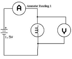
In a paper published in 1827, Georg Ohm described an experiment in which he measured voltage across and current through various simple electrical circuits containing various lengths of wire. A similar experiment is shown in Figure \(\PageIndex{1}\). This experiment is used to observe the current through a resistor that results from an applied voltage. In this simple circuit, a resistor is connected in series with a battery. The voltage is measured with a voltmeter, which must be placed across the resistor (in parallel with the resistor). The current is measured with an ammeter, which must be in line with the resistor (in series with the resistor).
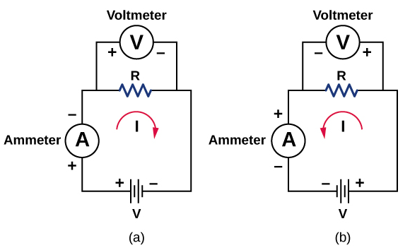
In this updated version of Ohm’s original experiment, several measurements of the current were made for several different voltages. When the battery was hooked up as in Figure \(\PageIndex{1a}\), the current flowed in the clockwise direction and the readings of the voltmeter and ammeter were positive. Does the behavior of the current change if the current flowed in the opposite direction? To get the current to flow in the opposite direction, the leads of the battery can be switched. When the leads of the battery were switched, the readings of the voltmeter and ammeter readings were negative because the current flowed in the opposite direction, in this case, counterclockwise. Results of a similar experiment are shown in Figure \(\PageIndex{2}\).
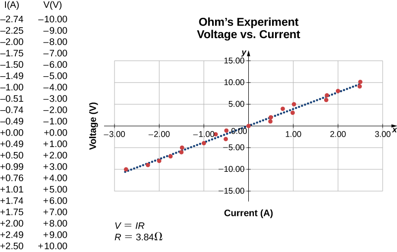
In this experiment, the voltage applied across the resistor varies from −10.00 to +10.00 V, by increments of 1.00 V. The current through the resistor and the voltage across the resistor are measured. A plot is made of the voltage versus the current, and the result is approximately linear. The slope of the line is the resistance, or the voltage divided by the current. This result is known as Ohm’s law :
\[V = IR \label{Ohms}\]
where V is the voltage measured in volts across the object in question, I is the current measured through the object in amps, and R is the resistance in units of ohms. As stated previously, any device that shows a linear relationship between the voltage and the current is known as an ohmic device. A resistor is therefore an ohmic device.
Example \(\PageIndex{1}\): Measuring Resistance
A carbon resistor at room temperature \((20^oC)\) is attached to a 9.00-V battery and the current measured through the resistor is 3.00 mA. (a) What is the resistance of the resistor measured in ohms? (b) If the temperature of the resistor is increased to \(60^oC\) by heating the resistor, what is the current through the resistor?
(a) The resistance can be found using Ohm’s law. Ohm’s law states that \(V = IR\), so the resistance can be found using \(R = V/I\).
(b) First, the resistance is temperature dependent so the new resistance after the resistor has been heated can be found using \(R = R_0 (1 + \alpha \Delta T)\). The current can be found using Ohm’s law in the form \(I = V/R\).
- Using Ohm’s law and solving for the resistance yields the resistance at room temperature: \[R = \dfrac{V}{I} = \dfrac{9.00 \, V}{3.00 \times 10^{-3} A} = 3.00 \times 10^3 \, \Omega = 3.00 k\Omega\]
- The resistance at \(60^oC\) can be found using \(R = R_0 (1 + \alpha \Delta T)\) where the temperature coefficient for carbon is \(\alpha = -0.0005\). \[R = R_0 (1 + \alpha \Delta T) = 3.00 \times 10^3 (1 - 0.0005 (60^oC - 20^oC)) = 2.94 \, k\Omega.\] The current through the heated resistor is \[I = \dfrac{V}{R} = \dfrac{9.00 \, V}{2.94 \times 10^3 \, \Omega} = 3.06 \times 10^{-3} A = 3.06 \, mA.\]
Significance
A change in temperature of \(40^oC\) resulted in a 2.00% change in current. This may not seem like a very great change, but changing electrical characteristics can have a strong effect on the circuits. For this reason, many electronic appliances, such as computers, contain fans to remove the heat dissipated by components in the electric circuits.
Exercise \(\PageIndex{1}\)
The voltage supplied to your house varies as \(V(t) = V_{max} sin \, (2\pi \, ft)\). If a resistor is connected across this voltage, will Ohm’s law \(V = IR\) still be valid?
Yes, Ohm’s law is still valid. At every point in time the current is equal to \(I(t) = V(t) /R\), so the current is also a function of time, \(I(t) = \dfrac{V_{max}}{R} \, sin \, (2\pi \, ft)\).
Simulation: PhET
See how Ohm’s law (Equation \ref{Ohms}) relates to a simple circuit. Adjust the voltage and resistance, and see the current change according to Ohm’s law. The sizes of the symbols in the equation change to match the circuit diagram.
Nonohmic devices do not exhibit a linear relationship between the voltage and the current. One such device is the semiconducting circuit element known as a diode . A diode is a circuit device that allows current flow in only one direction. A diagram of a simple circuit consisting of a battery, a diode, and a resistor is shown in Figure \(\PageIndex{3}\). Although we do not cover the theory of the diode in this section, the diode can be tested to see if it is an ohmic or a nonohmic device.
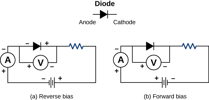
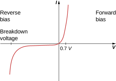
A plot of current versus voltage is shown in Figure \(\PageIndex{4}\). Note that the behavior of the diode is shown as current versus voltage, whereas the resistor operation was shown as voltage versus current. A diode consists of an anode and a cathode. When the anode is at a negative potential and the cathode is at a positive potential, as shown in part (a), the diode is said to have reverse bias. With reverse bias, the diode has an extremely large resistance and there is very little current flow—essentially zero current—through the diode and the resistor. As the voltage applied to the circuit increases, the current remains essentially zero, until the voltage reaches the breakdown voltage and the diode conducts current. When the battery and the potential across the diode are reversed, making the anode positive and the cathode negative, the diode conducts and current flows through the diode if the voltage is greater than 0.7 V. The resistance of the diode is close to zero. (This is the reason for the resistor in the circuit; if it were not there, the current would become very large.) You can see from the graph in Figure \(\PageIndex{4}\) that the voltage and the current do not have a linear relationship. Thus, the diode is an example of a nonohmic device.
Ohm’s law is commonly stated as \(V = IR\), but originally it was stated as a microscopic view, in terms of the current density, the conductivity, and the electrical field. This microscopic view suggests the proportionality \(V \propto I\) comes from the drift velocity of the free electrons in the metal that results from an applied electrical field. As stated earlier, the current density is proportional to the applied electrical field. The reformulation of Ohm’s law is credited to Gustav Kirchhoff, whose name we will see again in the next chapter.
FREE K-12 standards-aligned STEM
curriculum for educators everywhere!
Find more at TeachEngineering.org .
- TeachEngineering
- Ohm's Law I
Hands-on Activity Ohm's Law I
Grade Level: 10 (9-12)
Time Required: 3 hours
$3 is for light bulbs; the rest of the materials are available in most school classrooms
Group Size: 3
Activity Dependency: None
Subject Areas: Physics, Science and Technology
TE Newsletter
Engineering connection, learning objectives, materials list, worksheets and attachments, more curriculum like this, pre-req knowledge, introduction/motivation, vocabulary/definitions, investigating questions, troubleshooting tips, activity extensions, user comments & tips.

Ohm's law is the basis of all electrical systems. Electrical engineers use this equation to guide the design of electrical systems. Students need a strong foundation in Ohm's law while designing circuits on their own.
Application of the following:
- series/parallel circuits (ways to connect them and have an effect on V and I)
- circuit components
- devices that can be used to measure voltage and current
Educational Standards Each TeachEngineering lesson or activity is correlated to one or more K-12 science, technology, engineering or math (STEM) educational standards. All 100,000+ K-12 STEM standards covered in TeachEngineering are collected, maintained and packaged by the Achievement Standards Network (ASN) , a project of D2L (www.achievementstandards.org). In the ASN, standards are hierarchically structured: first by source; e.g. , by state; within source by type; e.g. , science or mathematics; within type by subtype, then by grade, etc .
International technology and engineering educators association - technology.
View aligned curriculum
Do you agree with this alignment? Thanks for your feedback!
State Standards
Hawaii - science, massachusetts - science.
Each group needs:
- 1 6.3V light bulb
- 1 lamp base
- 3 AA battery holders (including wires)
- 5 alligator clips
- two 1.5 volt batteries and/or power supply
- Ohm's Law Data Sheet
- Before beginning this activity, introduce students to electricity, current, voltage, resistance and Ohm's law.
- The functions and structures of circuit components such as conductors, loads and controllers should be discussed, and those existing in the circuit should be identified during the activity.
- Brief discussion of the structure of light bulbs, as well as batteries may also be included.
- (optional) Make sure students are familiar with the provided materials (wires, batteries, light bulbs, multimeter [see How to Use a Multimeter ] etc.), as well as safety precautions when working with different forms of electricity.
Where would we be today without electricity? Though we may not think about it often, our lives revolve around electricity – we depend upon it for light, heat, communication, entertainment and even healthcare. This power can not only be derived in the way we usually think about it – through power lines to our homes, schools and places of work – but also through self-contained power sources such as batteries. Since batteries are only able to provide a set amount of voltage (for example, a AA battery is 1.5 volts), how do you make devices with a higher voltage requirement work without increasing the voltage of the battery?
Background - Key Facts

Given that the resistance (R) of a device – in this case the light bulb – is constant, if we were to change the current or voltage being provided to the device, we would have an effect on the power.
A light's intensity is proportional to the power (P) supplied to it

By increasing the voltage or current supplied to a circuit, we can increase the power, and therefore increase the intensity of the light.
How can we change current or voltage (I or V)?
We can test parallel and series circuits to see how they affect the intensity of the bulb, or we can test the number of batteries connected to a circuit and the effect of this on I, V, or power.
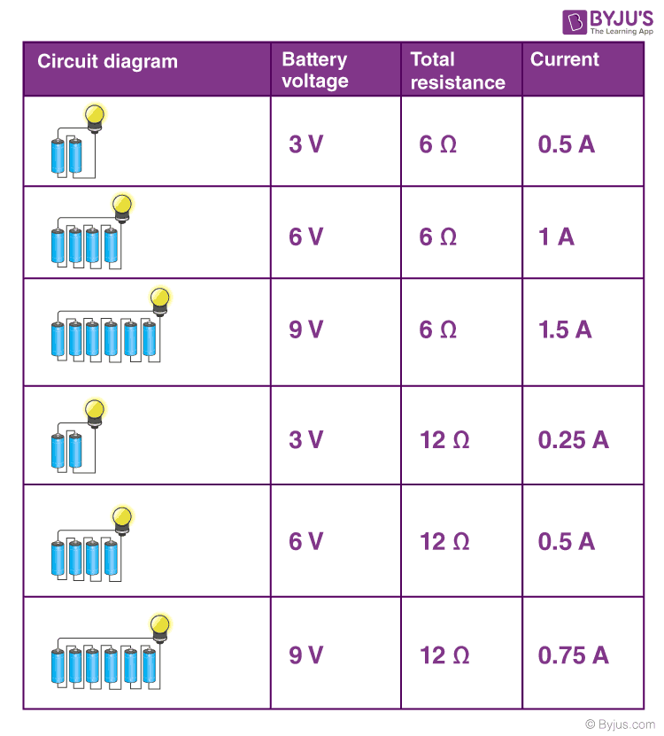
Batteries connected in a parallel circuit increase the available current (I) , but do not change the voltage (V) .
Batteries connected in a series circuit cause the voltage (V) to increase, resulting in a corresponding increase in current (I) .
With the Students
- Introduce the topic. Review definitions of keywords, as well as the topics mentioned in the Background section. Hand out the Ohm's Law Data Sheet and other materials.
- Group students . Depending upon the level of students, have them work on their own to develop experimental procedures that test the effect of the alignment of the batteries on voltage and current (and thus light intensity). Other students may follow the sample experimental procedure. Remind students that they are expected to answer the data sheet questions when the experiment is over with the information they gather.
- Comment on the effect of the number of batteries and their arrangement in the circuit on the power produced, and thus on the intensity of the light.
alternating current: Current that reverses direction at a regular rate.
ammeter: A device that measures current flowing through the circuit.
current: The flow of electrons. Current is read by opening the circuit and connecting the meter in series.
direct current: An electric current that flows in only one direction. The positive and negative terminals of a battery are always, respectively, positive and negative. The current always flows in the same direction between those two terminals.
light Intensity: The amount of light given off by a source such as a light bulb.
load: A device that consumes energy or power.
multimeter: A device that measures the current, voltage and resistance.
parallel circuit: A circuit that has two or more branches for separate currents from one voltage source.
potential: Electrical pressure, also called voltage.
power: The rate at which energy is delivered to something. (quantity / time): Measured in Watts.
resistance: The opposition of a body or substance to current passing through it, resulting in a change of electrical energy into heat, light, or another form of energy. Resistance is measured in Ohms. The resistance of a device is always the same (constant).
series: Circuit that only has one path for the electrons to flow.
voltage: The force that moves electrons. Voltage is read using the meter connected in parallel.
voltmeter: A device that measures the force with which electrons are flowing.
watt: The power expended when one ampere of direct current flows through a resistance of 1 Ohm.
Data Sheet & Questions: After students collect data on their data sheets, assign the questions as homework or a quiz/test. Review their answers to gauge their depth of comprehension.
- How is the brightness of the light bulb affected by the number of batteries connected in series? Explain.
- How is the brightness of the light bulb affected by the number of batteries connected in parallel? Explain.
- How is the current affected by the number of batteries connected in series? Explain.
- How is the current affected by the number of batteries connected in parallel? Explain.
- What are the advantages of connecting the batteries in parallel?
- What are the advantages of connecting the batteries in series?
- How might batteries be connected in a circuit to take advantage of both series and parallel characteristics?
Safety Issues
- Warn students that light bulbs get hot.
- Use the alligator clips and multimeters with care.
Take multimeter measurements quickly to avoid damage.
Conduct a demonstration that shows students just how much time it takes to use up the "juice" in a battery, and if it is better to use batteries in series or parallel. See the Ohm's Law 2 activity. This may be started before students begin to to work on the Ohm's Law 1 activity.

Students learn that charge movement through a circuit depends on the resistance and arrangement of the circuit components. In one associated hands-on activity, students build and investigate the characteristics of series circuits. In another activity, students design and build flashlights.

Students explore the basics of DC circuits, analyzing the light from light bulbs when connected in series and parallel circuits. Students measure and see the effect of power dissipation from the light bulbs.

Students are introduced to several key concepts of electronic circuits. They learn about some of the physics behind circuits, the key components in a circuit and their pervasiveness in our homes and everyday lives.

Students learn about current electricity and necessary conditions for the existence of an electric current. Students construct a simple electric circuit and a galvanic cell to help them understand voltage, current and resistance.

Brain, Marshall, Charles W. Bryant and Clint Pumphrey. How Batteries Work . Accessed November 6, 2011. http://electronics.howstuffworks.com/everyday-tech/battery.htm
Halliday, D., Resnick, R. and Walker, J. Fundamentals of Physics . USA: John Wiley & Sons, Inc., 2005.
Hambley, A. Electrical Engineering Principles and Application . USA: Prentice Hall, 2002.
Contributors
Supporting program, acknowledgements.
Creation of this activity was funded by Pratt & Whitney.
Last modified: April 19, 2021
Learn all about Ohm's law
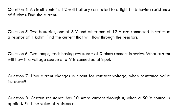
Ohm’s Law Practice Worksheet With Answers [PDF Download Available]
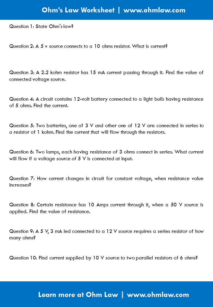
Ohm’s law worksheet contains top 10 worksheet problems with answers that help you practice and learn the Ohm’s law.
Ohm’s law Practice worksheet without solution
Ohm’s law Practice worksheet with solution
Download Ohm’s law practice worksheet (With answers)
Or continue learning below:
- ← Voltage Current Resistance Triangle [VIR Triangle]
Leave a Reply Cancel reply
Your email address will not be published. Required fields are marked *
Save my name, email, and website in this browser for the next time I comment.
- Current Electricity
Ohm’s law states the relationship between electric current and potential difference. The current that flows through most conductors is directly proportional to the voltage applied to it. Georg Simon Ohm, a German physicist was the first to verify Ohm’s law experimentally.
Ohm’s Law Explanation

One of the most basic and important laws of electric circuits is Ohm’s law.
Ohm’s law states that the voltage across a conductor is directly proportional to the current flowing through it, provided all physical conditions and temperatures remain constant.
Mathematically, this current-voltage relationship is written as,

In the equation, the constant of proportionality, R, is called Resistance and has units of ohms, with the symbol Ω.
The same formula can be rewritten in order to calculate the current and resistance respectively as follows:

Ohm’s law only holds true if the provided temperature and the other physical factors remain constant. In certain components, increasing the current raises the temperature . An example of this is the filament of a light bulb, in which the temperature rises as the current is increased. In this case, Ohm’s law cannot be applied. The lightbulb filament violates Ohm’s Law .
Relationship Between Voltage, Current and Resistance
Water Pipe Analogy for Ohm’s Law
Ohm’s Law describes the current flow through a resistance when different electric potentials (voltage) are applied at each end of the resistance . Since we can’t see electrons, the water-pipe analogy helps us understand the electric circuits better. Water flowing through pipes is a good mechanical system that is analogous to an electrical circuit.

Here, the voltage is analogous to water pressure, the current is the amount of water flowing through the pipe, and the resistance is the size of the pipe. More water will flow through the pipe (current) when more pressure is applied (voltage) and the bigger the pipe (lower the resistance).
The video below shows the physical demonstration of the Waterpipe analogy and explains to you the factors that affect the flow of current


Experimental Verification of Ohm’s Law
Ohm’s Law can be easily verified by the following experiment:
Apparatus Required:

- Initially, the key K is closed and the rheostat is adjusted to get the minimum reading in ammeter A and voltmeter V.
- The current in the circuit is increased gradually by moving the sliding terminal of the rheostat. During the process, the current flowing in the circuit and the corresponding value of potential difference across the resistance wire R are recorded.
- This way different sets of values of voltage and current are obtained.
- For each set of values of V and I, the ratio of V/I is calculated.
- When you calculate the ratio V/I for each case, you will come to notice that it is almost the same. So V/I = R, which is a constant.
- Plot a graph of the current against the potential difference, it will be a straight line. This shows that the current is proportional to the potential difference.
Similar Reading:
- Kirchhoff’s Law
- Faraday’s Laws
- Laws of Thermodynamics
Ohm’s Law Magic Triangle

Ohm’s Law Solved Problems
Example 1: If the resistance of an electric iron is 50 Ω and a current of 3.2 A flows through the resistance. Find the voltage between two points.
If we are asked to calculate the value of voltage with the value of current and resistance, then cover V in the triangle. Now, we are left with I and R or more precisely I × R.
Therefore, we use the following formula to calculate the value of V:
Substituting the values in the equation, we get
V = 3.2 A × 50 Ω = 160 V
Example 2: An EMF source of 8.0 V is connected to a purely resistive electrical appliance (a light bulb). An electric current of 2.0 A flows through it. Consider the conducting wires to be resistance-free. Calculate the resistance offered by the electrical appliance.
When we are asked to determine the value of resistance when the values of voltage and current are given, we cover R in the triangle. This leaves us with only V and I, more precisely V ÷ I.
R = 8 V ÷ 2 A = 4 Ω
Calculating Electrical Power Using Ohm’s Law
The rate at which energy is converted from the electrical energy of the moving charges to some other form of energy like mechanical energy, heat energy, energy stored in magnetic fields or electric fields, is known as electric power. The unit of power is the watt. The electrical power can be calculated using Ohm’s law and by substituting the values of voltage, current and resistance.
Formula to find power

What is a Power Triangle?

The power triangle can be employed to determine the value of electric power, voltage and current when the values of the other two parameters are given to us. In the power triangle, the power (P) is on the top and current (I) and voltage (V) are at the bottom.

Ohm’s Law Pie Chart

Ohm’s Law Matrix Table

Ohm’s Law Applications
The main applications of Ohm’s law are:
- To determine the voltage, resistance or current of an electric circuit.
- Ohm’s law maintains the desired voltage drop across the electronic components.
- Ohm’s law is also used in DC ammeter and other DC shunts to divert the current.
Limitations of Ohm’s Law
Following are the limitations of Ohm’s law:
- Ohm’s law is not applicable for unilateral electrical elements like diodes and transistors as they allow the current to flow through in one direction only.
- For non-linear electrical elements with parameters like capacitance, resistance etc the ratio ofvoltage and current won’t be constant with respect to time making it difficult to use Ohm’s law.
The video about conductance, resistance, and ohm’s law

Frequently Asked Questions – FAQs
What does ohm’s law state.
Ohm’s law states that the current through a conductor between two points is directly proportional to the voltage across the two points.
What can Ohm’s law be used for?
Ohm’s law is used to validate the static values of circuit components such as current levels, voltage supplies, and voltage drops.
Is Ohm’s law Universal?
No. Ohm’s law is not a universal law. This is because Ohm’s law is only applicable to ohmic conductors such as iron and copper but is not applicable to non-ohmic conductors such as semiconductors.
Why is Ohm’s law not applicable to semiconductors?
Ohm’s law doesn’t apply to semiconducting devices because they are nonlinear devices. This means that the ratio of voltage to current doesn’t remain constant for variations in voltage.
When does Ohm’s law fail?
Ohm’s law fails to explain the behaviour of semiconductors and unilateral devices such as diodes. Ohm’s law may not give the desired results if the physical conditions such as temperature or pressure are not kept constant.
Watch the video and solve important questions in the chapter Electricity Class 10

Put your understanding of this concept to test by answering a few MCQs. Click ‘Start Quiz’ to begin!
Select the correct answer and click on the “Finish” button Check your score and answers at the end of the quiz
Visit BYJU’S for all Physics related queries and study materials
Your result is as below
Request OTP on Voice Call
Leave a Comment Cancel reply
Your Mobile number and Email id will not be published. Required fields are marked *
Post My Comment
Nice app to a students
Nice app for us
nice thank u sir
Very useful study material
Good explanation!
These are good material
Like Very thanks 💐 byju ‘s team Very helpful notes Me is se apni project file banaya I like this app Very very thanks
I love this notes thank you Byju’s
Very nice app to study
This is very useful and informative for my 11th annual examination . Thank you byjus
- Share Share
Register with BYJU'S & Download Free PDFs
Register with byju's & watch live videos.

- Study Guides
- Homework Questions
M5.0 Assignment 5 Worksheet copy
- Electrical Engineering

IMAGES
VIDEO
COMMENTS
Ohm defines the unit of resistance of "1 Ohm" as the resistance between two points in a conductor where the application of 1 volt will push 1 ampere, or 6.241×10^18 electrons. This value is usually represented in schematics with the greek letter "Ω", which is called omega, and pronounced "ohm". Ohm's Law. Combining the elements of voltage ...
We measure I in amps = coul/sec and R in ohms = volts/amp = joule-sec/coul2. This is the form of Ohm's Law we will normally use. OHM'S LAW FOR OTHER GEOMETRIES. Consider a hollow spherical shell of conductivity σ. Concentric with the sphere is a solid conducting sphere of smaller radius (as shown).
This result is known as Ohm's law: V = IR (9.5.2) (9.5.2) V = I R. where V is the voltage measured in volts across the object in question, I is the current measured through the object in amps, and R is the resistance in units of ohms. As stated previously, any device that shows a linear relationship between the voltage and the current is ...
Ohm's law is the assertion that the current through a device is always directly proportional to the potential difference applied to the device. Here R is the proportionality constant which is the resistance of the object. The units are shown thusly: Below is a diagram of the circuit incorporating the power supply, ammeter, voltmeter, and the ...
Ohm's Law Practice Problems Using Ohm's Law, solve the following problems. Be sure to show all work. Formula: V (voltage)= I (current) X R (resistance) 1. What is the voltage if a resistance of 25 Ωproduces a current of 250 amperes? 2. What is the current produced by a voltage of 240 V through a resistance of 0.2 Ω? 3.
In equation form, Ohm's law is: V = IR. (2.1) Here, V is the voltage applied across the circuit in volts (V), I is the current flowing through the circuit in units of amperes (A), and R is the resistance of the circuit with units of ohms (Ω). Eq. 2.1 implies that, for a resistor with constant resistance, the current flowing through it is ...
80 Experiment 15: Ohm's Law Advance Reading Text: Ohm's Law, voltage, resistance, current. Lab Manual: Appendix B, Appendix C -DMM Objective The objective of this lab is to determine the resistance of several resistors by applying Ohm's Law. Students will also be introduced to the resistor color code and refresh their graphing skills. Theory
Question 13. One of the fundamental equations used in electricity and electronics is Ohm's Law: the relationship between voltage (E or V, measured in units of volts ), current (I, measured in units of amperes ), and resistance (R, measured in units of ohms ): E = I R I = E R R = E I E = I R I = E R R = E I. Where, E = Voltage in units of ...
Part 2: Ohm's Law Applied 8. Build a simple series circuit using R1, an ohmmeter, an ammeter, and a jumper. 9. Measure the equivalent resistance of the circuit us-ing the ohmmeter and record this value in the table. Include units and uncertainty. 10. Is the equivalent resistance what we expect it to be
problem 14. Calculate all of the parameters of the circuit shown in figure 6-20. Circuit parameters are: 50 Q 60 Q 40 1. 2. 3. 4. 5. Total resistance.
In this lab, students will build and analyze multi-resistive circuits to reinforce the learning of Ohm's Law, and Kirchhoff's Voltage and Current Laws. In doing so, students will view the voltage, current, and power implications of connecting loads (in this lab, the resistors serve as our loads) in series and in parallel.
Ohm's law is the relationship between voltage, current, and resistance: Ohm's law equation 1. Given that the resistance (R) of a device - in this case the light bulb - is constant, if we were to change the current or voltage being provided to the device, we would have an effect on the power. A light's intensity is proportional to the power ...
Ohm's law worksheet contains top 10 worksheet problems with answers that help you practice and learn the Ohm's law. Ohm's law Practice worksheet without solution. Ohm's law Practice worksheet with solution. Download Ohm's law practice worksheet (With answers) Or continue learning below: Solved: ← Voltage Current Resistance Triangle ...
2.5 Analyze simple series and parallel circuits using Ohm's Law and Kirchhoff's Law. 2.6 Implement knowledge of schematic and electronic design, circuit ... 4. LEARNING ACTIVITIES 4.1 Class assignments 4.2 Lab participation 5. EVALUATION 5.1 Quizzes/Exams 5.2 Assignments 5.3 Lab assignments 6. STUDENT RESPONSIBILITIES 6.1 Under AWC Policy ...
Ohm's Law summarizes these facts in a simple, easy-to-use equation. Voltage is proportional to Current. Voltage = Current × Resistance. (3) V = IR. The unit of electrical resistance is the ohm (Ω); it is equal to 1 volt/ampere. The illustration demonstrates this proportionality between voltage and current.
Ohm's law assignment - Free download as PDF File (.pdf) or read online for free.
Laboratory 6: Ohm's Law Assignment Sheet → You can clear and reset your screen by clicking the orange round arrow on the lower right side of the screen. After you complete part 1, reset your screen to have a fresh simulation page. Locate the current output box for use in the lab. You can adjust the following controls: Voltage Resistance 8.
Ohm's Law Solved Problems. Example 1: If the resistance of an electric iron is 50 Ω and a current of 3.2 A flows through the resistance. Find the voltage between two points. Solution: If we are asked to calculate the value of voltage with the value of current and resistance, then cover V in the triangle.
Ohms Law Investigation AIM The aim of this investigation is to verify ohms law by doing an experiment. UNDERLYING PHYSICS George Ohm was a German scientist. He found out that the voltage across a metal is proportional to the current through it as long as the temperature stays the same. This can be written as an equation V is the voltage
Assignment: Ohms Law - Free download as Word Doc (.doc / .docx), PDF File (.pdf), Text File (.txt) or read online for free. To investigate the relationship between current and voltage in Ohmic materials. To investigate the characteristic of resistor in series and parallel.
The symbol for ohm or unit is Ω, and this is representing the resistance. Now, in order to comprehend Ohm's Law is to imagine like a liquid circuit, we have our pump (battery; voltage), then it is flowing and meets it's resistance. This is the important part of Ohm's law and the resistance, is that if the resistance is bigger, then less ...
Terms in this set (15) Ohm's Law. - states that the current that flows in a circuit is directly proportional to the voltage and inversely proportional to the resistance. - is a basic but very useful law which is widely used from beginners to engineers to calculate current, voltage and resistance. - establishes the relationship between voltage ...
View Mod 10 Ohms Law Online Lab.pdf from PHYSICS 101 at Institute for Studies in Theoretical Physics and Mathematics (IPM). Name:_ Assignment: Ohm's Law Online Lab Part 1: Exploring the Simulation 1.
Name: _____ Top of Form M5.0 Assignment 5 Worksheet Applying Ohm's Law and Kirchhoff's Laws to simple and compound DC circuits, Analyzing R-C circuits Instructions ... Scan and save your worksheet, together with your handwritten or typed solutions to each problem as a .doc, .docx or .pdf or .rtf or an image file (png, jpg, jpeg or gif) file.