- PRO Courses Guides New Tech Help Pro Expert Videos About wikiHow Pro Upgrade Sign In
- EDIT Edit this Article
- EXPLORE Tech Help Pro About Us Random Article Quizzes Request a New Article Community Dashboard This Or That Game Popular Categories Arts and Entertainment Artwork Books Movies Computers and Electronics Computers Phone Skills Technology Hacks Health Men's Health Mental Health Women's Health Relationships Dating Love Relationship Issues Hobbies and Crafts Crafts Drawing Games Education & Communication Communication Skills Personal Development Studying Personal Care and Style Fashion Hair Care Personal Hygiene Youth Personal Care School Stuff Dating All Categories Arts and Entertainment Finance and Business Home and Garden Relationship Quizzes Cars & Other Vehicles Food and Entertaining Personal Care and Style Sports and Fitness Computers and Electronics Health Pets and Animals Travel Education & Communication Hobbies and Crafts Philosophy and Religion Work World Family Life Holidays and Traditions Relationships Youth
- Browse Articles
- Learn Something New
- Quizzes Hot
- This Or That Game New
- Train Your Brain
- Explore More
- Support wikiHow
- About wikiHow
- Log in / Sign up
- Education and Communications
- Electromagnetism

How to Solve a Series Circuit
Last Updated: December 26, 2023
This article was co-authored by Ralph Childers . Ralph Childers is a master electrician based in the Portland, Oregon area with over 30 years of conducting and teaching electrical work. Ralph received his B.S. in Electrical Engineering from the University of Louisiana at Lafayette and holds an Oregon Journeyman Electrical License as well as electrician licenses in Louisiana and Texas. This article has been viewed 293,181 times.
A series circuit is the simplest type of circuit: a single loop with no branching paths. The electrical charge leaves the positive terminal of the power supply, passes through each resistor or other components in turn, then returns to the negative terminal. The properties of series circuits are not hard to learn, but it can take some thinking to figure out how to use them.
Resistance, Voltage, and Current

- If you know any two of these values, use Ohm's Law to solve for the third. For example, if you know the resistance and voltage of a circuit, rearrange V = IR to I = V / R, and plug in the known values to solve for I, the current.
- Always use values form the same part of the circuit. If you are trying to solve for the resistance of a single resistor, you will need to know the voltage and current for that resistor. Do not use the voltage for the whole circuit.

- On a circuit diagram, a resistor looks like a zig-zag in the wire.

- Old-fashioned textbooks may use E to represent voltage instead of V. You may also see ΔV, meaning "change in voltage." The symbol Δ is the Greek letter delta, and means "change."

- Example 3: A series circuit plugged into a 220V source is connected to several light bulbs. You measure the voltage drop across a light bulb with resistance 100 Ω and get a result of 80V. How much current flows through this circuit? You know the values of V and R for the light bulb, so you can use Ohm's Law to solve for the current: I = 80V / 100Ω = 0.8 A (amps) Because the current is the same anywhere on a series circuit, the answer is 0.8 amps. Be careful: you cannot use the circuit's total voltage drop 220V. Ohm's Law only works if you use values for the same portion of the circuit, and this problem does not tell you the total resistance of the circuit.

- Fill out the chart with all values provided in the problem.

Power and Energy

- In the classroom, however, you do not need to find the power and energy unless the problem asks you to. If the problem only tells you to fill out a circuit diagram, use the method above to find resistance, voltage, and current.

- All the formulas in this section work for the circuit as a whole, or for individual components. Just make sure to use quantities that refer to the same portion of the circuit.

- The equations above give you a power result in watts. Multiply by seconds to get an energy result in Joules.
Expert Q&A
- If the internal resistance of the Power source was given (r), Then add it to the total resistance of the circuit (V=I*(R+r)) Thanks Helpful 0 Not Helpful 0
- Total voltage of circuit = sum of the voltages of all resistors connected in series. Thanks Helpful 0 Not Helpful 0

- Do not rely on these approaches for a parallel circuit, where the wire divides into two or more branches. Ohm's Law still applies to those, but many of the other formulas do not. Thanks Helpful 3 Not Helpful 0
You Might Also Like

- ↑ http://www.physicsclassroom.com/class/circuits/Lesson-4/Series-Circuits
- ↑ http://farside.ph.utexas.edu/teaching/302l/lectures/node57.html
- ↑ http://www.physicsclassroom.com/calcpad/circuits
About This Article

- Send fan mail to authors
Reader Success Stories
Laone Moipolai
Jun 10, 2021
Did this article help you?
Chaman Chauhan
May 4, 2017
Jun 18, 2022

Featured Articles

Trending Articles

Watch Articles

- Terms of Use
- Privacy Policy
- Do Not Sell or Share My Info
- Not Selling Info
wikiHow Tech Help Pro:
Develop the tech skills you need for work and life

StickMan Physics
Animated Physics Lessons
Series Circuit
Series circuits.
In a series circuit components like resistors and loads are connected in a single path. Current must go through every component in order starting from the positive terminal of the battery through everything in order and back to the negative battery terminal.
Series Circuit Handout to go along with the problems on this page and the PhET lab at the end.
- Practice and Series Circuit Virtual Lab Sheet

Series Circuits vs. Parallel Circuits
Series Circuits only have one path while parallel circuits we will see in a later unit have branches. Compare the pictures below each with three resistors.

Lights in a Series Circuit Compared to a Parallel Circuit
When lights are connected in a series circuit and one goes out the circuit becomes open and no other light works. This is because there is no path to the negative terminal of the battery when a circuit is open.
When lights are connected in parallel circuit and one light goes out the remaining ones stay on. No current will flow down the branch with the disconnected light bulb since that branch is open. Current will follow the other paths to the negative terminal of the battery leaving the other lights on.
Series Circuit Diagrams
To keep the models simple we will only places a battery and resistors in the circuits of our diagrams on this page. Remember that the longer line in the battery symbol is the positive terminal and the shorter line is the negative terminal. The convention is to have current run from the positive terminal to the negative terminal. Due to this convention the resistors are numbered in order. Here the resistors get their number resistor 1, resistor 2, and resistor 3 based on the flow of current starting from the positive terminal of the battery.
Series Circuit Rules
Voltage drop in a series circuit.
In a series circuit voltage drops across each resistor until the entire amount provided by the battery has dropped. If you add all the individual voltage drops of a series circuit together you can determine the voltage of the entire circuit (V T ) found at the power source.
V T = V 1 + V 2 + V 3 + …
Current in a Series Circuit
There is only one path in a series circuit for current to travel on. All current must run from the positive terminal to the negative terminal of the power source. Observe the animation of how the same current has to flow through every component of the circuit in series.
I T = I 1 = I 2 = I 3 = …
Resistance in a Series Circuit
Any resistor or load (device with a resistance) in a series acts like a speed bump in a series slowing current down . Since there is only one conductive path in series every device adds to total resistance.
R T = R 1 + R 2 + R 3 + …
Note that a wire itself has resistance and the less conductive a wire is the more resistance it would add to a circuit. We will ignore this in our examples below for simplicity and pretend the wire was 100% conductive.

Circuit Equations
Ohm's Law (V=IR) , Voltage equals current times resistance, can be used anywhere in the circuit but only at a single location.
See all the squares in red above, if you are using Ohm's law you can only use information in that location, the V,I, and R within a single square .
The location can be an individual resistor, for example resistor one with the variables Voltage (V 1 ), Current (I 1 ), Resistance (R 1 ). The location can also be at the battery, which is a measure that represents the overall circuits voltage (V T ), current (I T ), and Resistance (R T ).
At the battery the subscript T (ex. V T ) stands for total or of the circuit. Some equations sheets may use emf (ex. V emf ) or another notation, if there is any subscript other than a number it will likely be of the circuit.
When you are using information between different red blocks you must use the series circuit rules .
Start any problem by drawing out the circuit and have every resistor labeled as you see in the picture above. Then write in all your givens. Next, follow the basic steps to a series circuit problem.
Basic Steps To A Series Circuit Problem
#1 See if you can do Ohm's Law (V=IR) at any location in the circuit.
#2 See if you have current anywhere because that current will be the same everywhere following the series circuit rule below.
#3 Check if you can do any of the other series circuit rules.
You will continue to follow these steps over and over until everything in the circuit is complete. Follow our examples below until you feel comfortable to follow the steps solving series circuit problems on your own.
Example Problem 1

Example 1 Step 1
Here we don't have enough information to use Ohm's Law (V=IR) at any location so we need to look at the series circuit equations
We can use the last of the equations to solve for the resistance of the circuit (at the battery first). We only have three resistors so we leave off any other part not in this circuit from the equation
R T = R 1 + R 2 + R 3
R T = 15Ω + 20Ω + 5Ω = 40Ω

Example 1 Step 2
Now we have enough information to use Ohm's law at the battery to determine the current (I T ) at the battery
I T =V T /R T
I T =80V/40Ω = 2A

Example 1 Step 3
Now that we know current at any location, in this case the battery, we know it everywhere in a series circuit
I T = I 1 = I 2 = I 3

Example 1 Step 4
Now we have enough information to solve for voltage everywhere using Ohm's Law (V=IR)
V 1 = I 1 x R 1
V 1 = 2A x 15Ω = 30V
V 2 = I 2 x R 2
V 2 = 2A x 20Ω = 40 V
V 3 = I 3 x R 3
V 3 = 2A x 5Ω = 10 V

It is important to make one final check. Since we finished using Ohm's Law to solve for V 3 , lets make sure this last step also fits with the series circuit rule.
V T = V 1 + V 2 + V 3
80V = 30V + 40V + 10V
This is also mathematically correct so we know we solved for all the parts of this circuit correctly. If it did not we would know we had an error and would have to trace back our steps or starting over is sometimes easier.
Example Problem 2
Note: While our example stick to whole numbers for simplicity, this would be very uncommon and you would normally have decimals . Do not be shocked if you have decimals , just make sure all the rules are followed and do a final check as presented in the examples below.

Example 2 Step 1
You have enough information to start this circuit at the first resistor using Ohm's Law (V=IR)
V 1 = I 1 x R 1 rearranges to I 1 = V 1 /R 1 when solving for current.
I 1 = 6V/3Ω = 2A

Example 2 Step 2
Now that we know current at the at one location, the first resistor, we know it's the same everywhere following series circuit rules.
2A = 2A = 2A = 2A

Example 2 Step 3
Now we have enough information to use Ohm's Law (V=IR) to solve for resistance of the circuit (at the battery) and voltage at resistor 2
V T = I T x R T rearranges to R T = V T /I T
R T = V T /I T
R T = 12V/2A = 6Ω
V 2 = 2A x 2Ω = 4V
Now our circuit looks like this

Example 2 Step 4
From here we can solve for either voltage or resistance of resistor 3 using the overall series circuit rules.
12V = 6V + 4V + V 3
V 3 = 12V - 6V - 4V
6Ω = 3Ω + 2Ω + R 3
R 3 = 6Ω - 3Ω - 2Ω

Since we solved for R 3 last using series circuit rules do the final check at resistor three making sure it follows Ohm's Law at this location as well.
2V = 2A x 1Ω
It makes the final check so we know we solved for the parts of this circuit correctly.
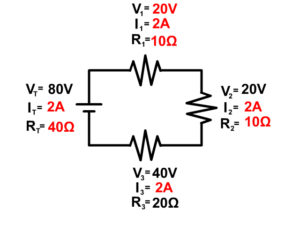
Example Problem 3

Example 3 Step 1
In this circuit we don't have enough information to start with Ohm's Law since we don't have two out of three parts of Ohm's Law at any one location.
We do have enough information to start with the series circuit resistor rule. R T = R 1 + R 2 + R 3
20Ω = R 1 + 10Ω + 4Ω
R 1 = 20Ω - 10Ω - 4Ω = 6Ω
Our circuit now looks like this

Example 3 Step 2
Now we can solve for current at resistor 1 using Ohm's Law
I 1 = V 1 /R 1
I 1 = 12V/6Ω = 2A

Example 3 Step 3
Now that we know current in one location we know the current everywhere in the circuit following the series circuit rules.

Example 3 Step 4
Now use Ohm's Law (V=IR) to solve for all the remaining components since we have enough information to do so.
V T = I T x R T
V T = 2A x 20Ω = 40V
V 2 = 2A x 10Ω = 20V
V 3 = 2A x 4Ω = 8V

Since we ended by solving for V 3 using Ohm's Law, our final check is to make sure voltage also follow the series circuit rules for voltage.
40V = 12V + 20V + 8V
This is a correct mathematical statement so we know we solved our series circuit correctly.
Notice the following about some series circuit problems
Some problems as the one seen below are drawn showing multimeters taking the reading of the current as seen below. This is not part of the circuit and is just taking a reading.

You would rewrite the problem above taking out the multimeters and placing the readings into the problem and start the problem as seen in example 4 below.
Example Problem 4

Try example 4 on your own and click "See Solution" to check your answers.
See Solution
Another Way Current Can Be Given In A Series Circuit Problem
Be aware that current can also be drawn into a problem in the wire and not at a single resistor. This is not an additional resistor but seeing the current drawn as a circle over the wire shows you the current in that wire. Since there is only one wire going from the previous resistor to the new resistor, you know in series both of those must have that current as well. See the picture to see a visual of this.
Circuit Construction Kit
The following PhET circuit construction kit can help you understand the workings of circuits more.
CLICK HERE FOR THE SERIES CIRCUIT LAB SHEET
Go to the following website is the embedded version is not working
https://phet.colorado.edu/sims/html/circuit-construction-kit-dc/latest/circuit-construction-kit-dc_en.html
- Continue to Parallel Circuits
- Back to the Main Current and Circuits Page
- Back to the Stickman Physics Home Page
- Equation Sheet
Terms and Conditions - Privacy Policy

- school Campus Bookshelves
- menu_book Bookshelves
- perm_media Learning Objects
- login Login
- how_to_reg Request Instructor Account
- hub Instructor Commons
- Download Page (PDF)
- Download Full Book (PDF)
- Periodic Table
- Physics Constants
- Scientific Calculator
- Reference & Cite
- Tools expand_more
- Readability
selected template will load here
This action is not available.
5.6: Circuit Problem Solving
- Last updated
- Save as PDF
- Page ID 17165

- Dina Zhabinskaya
Solving Electric Circuit Problems
When tackling a circuit problem you may need to figure out the equivalent resistance of the circuit, voltage drops across resistors, total current coming out of the battery or current through specific resistors, power dissipated by resistors or provided by the battery, relative brightness of light bulbs in a circuit, the effect of a shorted resistor, or a burnt one, and more.
Below are a few useful steps to follow. Even though these basics steps are provided, it is never a good idea to follow a procedure verbatim. This procedure is a good starting guide of tacking some circuit problems, but might not apply to all of them in the order provided. As you start working with more advanced scenarios, think of ways of how you can work backwards, follow the steps in different order, or only use some of the steps to solve your particular problem most efficiently.
Circuit problem solving procedure:
1) Calculate the equivalent resistance of the circuit. First combine all the series resistors and then calculate the parallel ones. Use the following equations:
\[\text{series}:~~R_{eq}=\sum_i^n R_i\]
\[\text{parallel}:~~\dfrac{1}{R_{eq}}=\sum_i^n \dfrac{1}{R_i}\]
2) Use your result of equivalent resistance to find the total current coming out of the battery:
\[I_{tot}=\dfrac{\mathcal E}{R_{eq}}\]
3) Apply the loop rule to all the loops present in the circuit in order to find the relationship between voltage drops and emf of battery. Make sure you are consistent with the direction of the loop you choose. If your loop takes you from a negative to the positive terminal of the battery, you will get, \(+\mathcal E\). If you loop takes you across a resistor in the direction of the current, then the correct sign of the voltage difference should be negative, \(\Delta V=-IR\). In general for any given loop, the following must be true:
\[\sum \mathcal E+\sum \Delta V =0\]
4) Apply the junction rule at all the junctions to find the relationship between the current going into the junction and the individual currents in each of n paths:
\[I_{in}=\sum_i^n I_i\]
Example \(\PageIndex{1}\)
For the circuit show below find the current and voltage for each of the five resistors.

It is a good idea to start by labeling all the currents and voltage as shown below.

Since all the resistances are known, the first natural step is to find the equivalent resistance. For this particular circuit the best way to combine resistors is: resistors 4 and 5 are in parallel, their combination \(R_{45}\) is in series with \(R_3\). The combination of 3,4, and 5, \(R_{345}\) is in parallel with 2, and their combination, \(R_{2345}\) is in series with \(R_1\).
First, calculating \(R_4\) and \(R_5\) in parallel:
\(\dfrac{1}{R_{45}}=\dfrac{1}{R_4}+\dfrac{1}{R_5}=\dfrac{1}{2\Omega}+\dfrac{1}{6\Omega}=\dfrac{2}{3\Omega}\)
\(R_{45}=\dfrac{3}{2}\Omega\)
Combining \(R_3\) in series with \(R_{45}\):
\(R_{345}=R_3+R_{45}=18.5\Omega+1.5\Omega=20\Omega\)
Combining \(R_3\) in parallel with \(R_{345}\):
\(\dfrac{1}{R_{2345}}=\dfrac{1}{R_2}+\dfrac{1}{R_{345}}=\dfrac{1}{5\Omega}+\dfrac{1}{20\Omega}=\dfrac{1}{4\Omega}\)
\(R_{2345}=4\Omega\)
And finally combining \(R_1\) in series with \(R_{2345}\) to find the equivalent resistance of this circuit:
\(R_{eq}=R_1+R_{2345}=10\Omega+4\Omega=14\Omega\)
Resistor 1 is the only resistors which is in series with the battery, so the current through resistor 1, \(I_1\), will be equal to the total current coming out of the battery:
\(I_1=I_{tot}=\dfrac{\mathcal E}{R_{eq}}=\dfrac{5V}{14\Omega}=0.357 A\)
Once we know the current through 1, we can find the voltage across resistor 1:
\(\Delta V_1=-I_1R_1=0.357A\times 10\Omega=-3.57V\)
Now we can apply the loop rule to the first loop on the left that goes through the battery, resistor 1, and resistor 2 to find the voltage across resistor 2:
\(\mathcal E+\Delta V_1+\Delta V_2=0\)
\(\Delta V_2=-\mathcal E-\Delta V_1=-5V+3.57V=-1.43V\)
Since we know the voltage across resistors 2, we can figure out the current through that resistor, \(I_2\):
\(I_2=\dfrac{-\Delta V_2}{R_2}=\dfrac{1.43V}{5\Omega}=0.286A\)
Next, we can use the junction rule to find the amount of current that goes to the other branch and through resistors 3, \(I_3\):
\(I_1=I_2+I_3\)
\(I_3=I_1-I_2=0.357A-0.286A=0.071A\)
Knowing the current, allows us to find the voltage drop across \(R_3\):
\(\Delta V_3=-I_3R_3=-0.071A\times 18.5\Omega=-1.3135V\)
Applying the loop rule to the outermost loop we can find the voltage drop across the parallel combination of \(R_4\) and \(R_5\):
\(\mathcal E+\Delta V_1+\Delta V_3+\Delta V_{45}=0\)
\(\Delta V_{45}=-\mathcal E-\Delta V_1-\Delta V_3=-5V+3.57V+1.3135V=-0.1165V\)
Lastly, since we know the voltage drop across the parallel set of 4 and 5, it must equal to the voltage drops across each one of the resistors, \(\Delta V_{45}=\Delta V_{4}=\Delta V_5\). Using this, we can find the currents \(I_4\) and \(I_5\):
\(I_4=\dfrac{-\Delta V_4}{R_4}=\dfrac{0.1165V}{2\Omega}=0.0583A\)
\(I_4=\dfrac{-\Delta V_5}{R_5}=\dfrac{0.1165V}{6\Omega}=0.0194A\)
Example \(\PageIndex{2}\)
While playing with electronics in class you build a circuit with one battery and five resistors. You calculate the following equivalent resistance:
\(R_{eq}=\Big[\dfrac{1}{R_1+\Big(\dfrac{1}{R_2}+\dfrac{1}{R_3}\Big)^{-1}}+\dfrac{1}{R_4}\Big]^{-1}+R_5\)
a) Draw a possible circuit connected to a battery that has the above equivalent resistance. Clearly mark each resistor with \(R_1\), \(R_2\), \(R_3\), \(R_4\), and \(R_5\).
b) Assume that \(R_{eq}=25\Omega\), \(R_4=R_1+\Big(\dfrac{1}{R_2}+\dfrac{1}{R_3}\Big)^{-1}\), and \(R_2=2R_3\). If the circuit is connected to a 10V battery, how much current will flow through \(R_2\)?
c) If \(R_2\) was shorted out, what would be the new equivalent resistance in terms of the resistor numbers? Would the total current coming out of the battery increase, decrease, or stay the same?
a) The equation above states that \(R_5\) is in series with a parallel branch which contains \(R_4\) in one path and \(R_1+\Big(\dfrac{1}{R_2}+\dfrac{1}{R_3}\Big)^{-1}\) in the other. The other path has \(R_1\) in series with a parallel branch containing \(R_2\) and \(R_3\) as shown.

b) The total current coming out of the battery is
\(I=\dfrac{\mathcal E}{R_{eq}}=\dfrac{10V}{25\Omega}=0.4A\)
The two paths of the main parallel branch have equal resistance, so the current will split equally at the junction. This means that half the total current will flow through \(R_1\), which is \(0.2 A\). The current will split further between \(R_2\) and \(R_3\). Since \(R_2=2R_3\), \(R_3\) will get double the current of \(R_2\) since their voltage drops have to be the same.
\(\Delta V_2=\Delta V_3\)
\(I_2R_3=I_3R_3\)
\(I_2=\dfrac{I_3}{2}\)
Using the fact that \(I_2+I_3=0.2A\) and the above result we get:
\(I_2=\dfrac{I_3}{2}=\dfrac{0.2-I_2}{2}\)
Resulting in \(I_2=\dfrac{1}{15}A\).
c) If \(R_2\) was shorted out, all the current going through \(R_1\) would go though the wire, so \(R_2\) and \(R_3\) would not get any current and are no longer part of the active circuit. The new equivalent resistance becomes:
\(R_{eq}=R_5+\Big(\dfrac{1}{R_4}+\dfrac{1}{R_1}\Big)^{-1}\)
Since the lower branch now has reduced resistance, the combined resistance between \(R_4\) and the lower branch will decrease, thus the total equivalent resistance of the entire circuit will be decreased. Smaller total resistance means that the total current will increase since, \(I=\dfrac{\mathcal E}{R_{eq}}\).
Example \(\PageIndex{3}\)
You build the circuit shown here and find that the brightness of light bulb 1 twice as bright (double power) as 3, and the brightness of light bulb 1 is half as bright as 2 (half power).

a) You know that light bulb 3 has resistance of \(36\Omega\). Find the resistance of light bulbs 1 and 2.
b) You add a wire across light bulb 1. Describe what happens to the brightness of each light bulb (gets brighter, gets dimmer, stays the same brightness, or is not lit) compared to the original circuit.
c) If light bulb 1 in the original circuit burnt out instead, what happens to the brightness of each light bulb (gets brighter, gets dimmer, stays the same brightness, or is not lit) compared to the original circuit?
a) Resistors \(R_1\) and \(R_2\) have the same current since they are in series, \(I_1=I_2\). Since \(P=I^2R\) and \(P_2=2P_1\) we conclude that:
\(P_2=I^2R_2=2P_1=2I^2R_1\)
\(R_2=2R_1\)
When it comes to resistors in parallel, it is often simpler to think in terms of voltage drops rather than current. The voltage drop across \(R_3\) has to equal to the voltage drop across the other branch which includes the sum of voltage drop across \(R_1\) and \(R_2\):
\(\Delta V_3=\Delta V_1+\Delta V_2\)
Since \(R_2=2R_1\) and \(\Delta V=-IR\), \(\Delta V_2=2\Delta V_1\), and the above equation becomes:
\(\Delta V_3=3\Delta V_1\)
We also know that \(P_1=2P_3\). Using \(P=\dfrac{\Delta V^2}{R}\) we find that:
\(\dfrac{\Delta V_1^2}{R_1}=2\dfrac{\Delta V_3^2}{R_3}\)
Using the result \(\Delta V_3=3\Delta V_1\) we find that:
\(\dfrac{\Delta V_1^2}{R_1}=18\dfrac{\Delta V_1^2}{R_3}\)
\(R_3=18R_1\)
Using \(R_3=36\Omega\), we find that \(R_1=2\Omega\), and using \(R_2=2R_1\), we find that \(R_2=4\Omega\).
b) Adding a wire across \(R_1\) shorts out \(R_1\), since all the current will go through the wire. So \(R_1\) will not be lit. The voltage drop across \(R_2\) has to increase, since due to the loop rule applied to the bottom loop, all the voltage now drops across rather \(R_2\), \(\mathcal E=-\Delta V_2\), rather than being split between \(R_1\) and \(R_2\) in the original circuit. Since power is proportional to voltage drop, 2 gets brighter. The voltage drop across \(R_3\) doesn’t change due to loop rule for top loop, \(\mathcal E=-\Delta V_3\), so 3 stays the same brightness.
c) If light bulb 1 burns out, the path on the lower loop is broken (there is no place for current to go), so both \(R_1\) and \(R_2\) will not be lit. The voltage drop across \(R_3\) doesn’t change due to loop rule for top loop as in the argument for b), so 3 stays the same brightness.
32.8: RLC Series Circuit: Problem-Solving
Chapter 1: units, dimensions, and measurements, chapter 2: vectors and scalars, chapter 3: motion along a straight line, chapter 4: motion in two or three dimensions, chapter 5: newton's laws of motion, chapter 6: application of newton's laws of motion, chapter 7: work and kinetic energy, chapter 8: potential energy and energy conservation, chapter 9: linear momentum, impulse and collisions, chapter 10: rotation and rigid bodies, chapter 11: dynamics of rotational motions, chapter 12: equilibrium and elasticity, chapter 13: fluid mechanics, chapter 14: gravitation, chapter 15: oscillations, chapter 16: waves, chapter 17: sound, chapter 18: temperature and heat, chapter 19: the kinetic theory of gases, chapter 20: the first law of thermodynamics, chapter 21: the second law of thermodynamics, chapter 22: electric charges and fields, chapter 23: gauss's law, chapter 24: electric potential, chapter 25: capacitance, chapter 26: current and resistance, chapter 27: direct-current circuits, chapter 28: magnetic forces and fields, chapter 29: sources of magnetic fields, chapter 30: electromagnetic induction, chapter 31: inductance, chapter 32: alternating-current circuits, chapter 33: electromagnetic waves.
The JoVE video player is compatible with HTML5 and Adobe Flash. Older browsers that do not support HTML5 and the H.264 video codec will still use a Flash-based video player. We recommend downloading the newest version of Flash here, but we support all versions 10 and above.
Consider an RLC series circuit with a 16 ohm resistor, 0.08 henry inductor, and 0.04 farad capacitor connected to a 120 volt source with a 50 hertz frequency. Determine the circuit's impedance, phase angle, current amplitude, and voltage amplitude across each circuit element.
To solve the problem, identify the known and unknown quantities.
By recalling the reactance equations and substituting the terms, the inductive and capacitive reactance in the circuit can be determined.
Using the impedance equation and substituting the resistance and reactance values, the impedance of the circuit can be determined.
Recalling and substituting the terms in the phase angle equation, the phase angle between the current and voltage can be determined.
In an RLC series circuit, impedance is a ratio of voltage and current amplitude; by rearranging the equation, the current amplitude can be determined.
The voltage amplitude across each element can be determined as the product of the element's current and resistance or reactance.
By substituting the value in the equations, the voltage amplitude across each element can be determined.
Consider an AC generator with a frequency of 50 hertz and a voltage of 120 volts. The AC generator is connected to an RLC series circuit with a 20-ohms resistor, a 0.2-henry inductor, and a 0.05-farad capacitor. Determine the impedance, current amplitude, and phase difference between the generator's current and emf.
To solve the problem, first, determine the known and unknown quantities in the problem. Recalling the reactance equation for the inductor and capacitor and substituting the values, the inductive and capacitive reactance can be determined as follows:

Impedance measures the combined effect of resistance, capacitive, and inductive reactance. Next, recall the impedance equation and substitute the resistance, inductive reactance, and capacitive reactance. By simplifying the equation, the impedance in the circuit can be determined as follows:

The current's amplitude is the ratio of the voltage's amplitude to the circuit's impedance. Thus, by substituting the known values, the current amplitude can be calculated as follows:

Lastly, recall the phase angle equation in the RLC circuit. By substituting the resistance and reactance values, the phase difference between the current and the emf of the generator can be calculated as follows:

The phase angle is positive because the reactance of the inductor is larger than the reactance of the capacitor.
- OpenStax. (2019). University Physics Vol. 2 . [Web version], Pg 396 - 398. Retrieved from https://openstax.org/books/university-physics-volume-2@8ede2ba/pages/15-3-rlc-series-circuits-with-ac
Get cutting-edge science videos from J o VE sent straight to your inbox every month.
mktb-description
We use cookies to enhance your experience on our website.
By continuing to use our website or clicking “Continue”, you are agreeing to accept our cookies.
Series and Parallel Circuits
Learn about series and parallel circuits., series and parallel circuits lesson, series vs. parallel: what's the difference.
In circuits, the two basic ways to connect components are in series and in parallel. The words "series" and "parallel" simply tell us how many paths there are for the electric current to take. In a series circuit, the electric current has only one path to take. In a parallel circuit, there is more than one path for the electric current to take.
Series Circuit Basics
When components are connected in series, the electric current must take a single path. The series circuit below consists of a DC voltage source with three resistors connected in series.

The electric current has only a single path through the resistors — therefore it is a series circuit. An easy way to remember how a series circuit works: the components are in a series , connected one after the other just like the games in a baseball series.
Parallel Circuit Basics
When components are connected in parallel, the electric current takes more than one path. The parallel circuit below consists of a DC voltage source with three resistors connected in parallel, with three parallel branches (one per resistor).

The electric current takes each of the three paths created by each resistor's branch in the circuit. It is called a parallel circuit because it is graphically represented to have multiple paths of electric current that are parallel to each other.
Calculating Voltage, Current, and Resistance
There are three basic parameters we study when dealing with series and parallel circuits.
- The voltage across a component
- The current through a component
- The resistance of a component
The relationship between these three parameters is governed by Ohm's law, given as V = IR, where V is voltage, I is current, and R is resistance. However, parallel circuits add some complexity to calculating these. Let's go through how to deal with calculating the three parameters for series circuits and for parallel circuits.
How to Solve a Series Circuit
For a series circuit like the one below, we follow these three basic rules.
- The total resistance of the circuit equals the sum of all resistors. R total = R 1 + R 2 + ... + R n
- The current through the circuit is equal to the DC voltage divided by the total resistance of the circuit. I total = V total ⁄ R total
- The voltage across a component is V = IR, where R is the resistance of the component. V n = I total ×R n
Let's work together to find the voltage across each resistor and the current through the circuit, based on the resistance of each component.
We can call the three resistors R 1 , R 2 , and R 3 respectively. Also, we will call the DC voltage source V 0 . To find the current through the circuit, we must first find the total resistance.
Following series circuit rule #1, we know that adding all three resistors will give us the total resistance. So, R total = R 1 + R 2 + R 3 .
Then, following rule #2, we get I total = V 0 ⁄ R total . We now know the total resistance and current of the circuit!
Lastly, we will quickly find the voltage across each resistor. Rule #3 and Ohm's law tell us that V = IR. So, V 1 = I total ×R 1 , V 2 = I total ×R 2 , and V 3 = I total ×R 3 .
How to Solve a Parallel Circuit
For a parallel circuit like the one below, we follow these four basic rules.
- The reciprocal of the total resistance of the circuit equals the sum of the reciprocals of every branch's resistance. 1 ⁄ R total = 1 ⁄ R b1 + 1 ⁄ R b2 + ... + 1 ⁄ R bn
- The current through the circuit is equal to the DC voltage source divided by the total resistance of the circuit, but the current through each branch is a fraction of the total current and dependent on that branch's resistance (see rule #4). I total = V total ⁄ R total
- The voltage across each branch is equal to the DC voltage source for the branches. V bn = V total
- The current through each branch is equal to the voltage divided by the branch's resistance. I bn = V bn ⁄ R bn
Let's work together to find the current through each branch.
We can call the three branches and their resistors B1, B2, B3, R 1 , R 2 , and R 3 respectively. Also, we will call the DC voltage source V 0 .
Following parallel circuit rule #4, we know that we can apply Ohm's law to each individual branch because rule #3 tells us the voltage across each branch. Applying rule #3 gives us V b1 = V 0 , V b2 = V 0 , and V b3 = V 0 .
Now, applying rule #4, we get I b1 = V b1 ⁄ R 1 , I b2 = V b2 ⁄ R2 , and I b3 = V b3 ⁄ R3 . We now know the current through each parallel branch of the circuit!
Learning math has never been easier. Get unlimited access to more than 168 personalized lessons and 73 interactive calculators. Join Voovers+ Today 100% risk free. Cancel anytime.
Insert/edit link
Enter the destination URL
Or link to existing content

- TPC and eLearning
- Read Watch Interact
- What's NEW at TPC?
- Practice Review Test
- Teacher-Tools
- Subscription Selection
- Seat Calculator
- Ad Free Account
- Edit Profile Settings
- Classes (Version 2)
- Student Progress Edit
- Task Properties
- Export Student Progress
- Task, Activities, and Scores
- Metric Conversions Questions
- Metric System Questions
- Metric Estimation Questions
- Significant Digits Questions
- Proportional Reasoning
- Acceleration
- Distance-Displacement
- Dots and Graphs
- Graph That Motion
- Match That Graph
- Name That Motion
- Motion Diagrams
- Pos'n Time Graphs Numerical
- Pos'n Time Graphs Conceptual
- Up And Down - Questions
- Balanced vs. Unbalanced Forces
- Change of State
- Force and Motion
- Mass and Weight
- Match That Free-Body Diagram
- Net Force (and Acceleration) Ranking Tasks
- Newton's Second Law
- Normal Force Card Sort
- Recognizing Forces
- Air Resistance and Skydiving
- Solve It! with Newton's Second Law
- Which One Doesn't Belong?
- Component Addition Questions
- Head-to-Tail Vector Addition
- Projectile Mathematics
- Trajectory - Angle Launched Projectiles
- Trajectory - Horizontally Launched Projectiles
- Vector Addition
- Vector Direction
- Which One Doesn't Belong? Projectile Motion
- Forces in 2-Dimensions
- Being Impulsive About Momentum
- Explosions - Law Breakers
- Hit and Stick Collisions - Law Breakers
- Case Studies: Impulse and Force
- Impulse-Momentum Change Table
- Keeping Track of Momentum - Hit and Stick
- Keeping Track of Momentum - Hit and Bounce
- What's Up (and Down) with KE and PE?
- Energy Conservation Questions
- Energy Dissipation Questions
- Energy Ranking Tasks
- LOL Charts (a.k.a., Energy Bar Charts)
- Match That Bar Chart
- Words and Charts Questions
- Name That Energy
- Stepping Up with PE and KE Questions
- Case Studies - Circular Motion
- Circular Logic
- Forces and Free-Body Diagrams in Circular Motion
- Gravitational Field Strength
- Universal Gravitation
- Angular Position and Displacement
- Linear and Angular Velocity
- Angular Acceleration
- Rotational Inertia
- Balanced vs. Unbalanced Torques
- Getting a Handle on Torque
- Torque-ing About Rotation
- Properties of Matter
- Fluid Pressure
- Buoyant Force
- Sinking, Floating, and Hanging
- Pascal's Principle
- Flow Velocity
- Bernoulli's Principle
- Balloon Interactions
- Charge and Charging
- Charge Interactions
- Charging by Induction
- Conductors and Insulators
- Coulombs Law
- Electric Field
- Electric Field Intensity
- Polarization
- Case Studies: Electric Power
- Know Your Potential
- Light Bulb Anatomy
- I = ∆V/R Equations as a Guide to Thinking
- Parallel Circuits - ∆V = I•R Calculations
- Resistance Ranking Tasks
- Series Circuits - ∆V = I•R Calculations
- Series vs. Parallel Circuits
- Equivalent Resistance
- Period and Frequency of a Pendulum
- Pendulum Motion: Velocity and Force
- Energy of a Pendulum
- Period and Frequency of a Mass on a Spring
- Horizontal Springs: Velocity and Force
- Vertical Springs: Velocity and Force
- Energy of a Mass on a Spring
- Decibel Scale
- Frequency and Period
- Closed-End Air Columns
- Name That Harmonic: Strings
- Rocking the Boat
- Wave Basics
- Matching Pairs: Wave Characteristics
- Wave Interference
- Waves - Case Studies
- Color Addition and Subtraction
- Color Filters
- If This, Then That: Color Subtraction
- Light Intensity
- Color Pigments
- Converging Lenses
- Curved Mirror Images
- Law of Reflection
- Refraction and Lenses
- Total Internal Reflection
- Who Can See Who?
- Formulas and Atom Counting
- Atomic Models
- Bond Polarity
- Entropy Questions
- Cell Voltage Questions
- Heat of Formation Questions
- Reduction Potential Questions
- Oxidation States Questions
- Measuring the Quantity of Heat
- Hess's Law
- Oxidation-Reduction Questions
- Galvanic Cells Questions
- Thermal Stoichiometry
- Molecular Polarity
- Quantum Mechanics
- Balancing Chemical Equations
- Bronsted-Lowry Model of Acids and Bases
- Classification of Matter
- Collision Model of Reaction Rates
- Density Ranking Tasks
- Dissociation Reactions
- Complete Electron Configurations
- Elemental Measures
- Enthalpy Change Questions
- Equilibrium Concept
- Equilibrium Constant Expression
- Equilibrium Calculations - Questions
- Equilibrium ICE Table
- Intermolecular Forces Questions
- Ionic Bonding
- Lewis Electron Dot Structures
- Limiting Reactants
- Line Spectra Questions
- Mass Stoichiometry
- Measurement and Numbers
- Metals, Nonmetals, and Metalloids
- Metric Estimations
- Metric System
- Molarity Ranking Tasks
- Mole Conversions
- Name That Element
- Names to Formulas
- Names to Formulas 2
- Nuclear Decay
- Particles, Words, and Formulas
- Periodic Trends
- Precipitation Reactions and Net Ionic Equations
- Pressure Concepts
- Pressure-Temperature Gas Law
- Pressure-Volume Gas Law
- Chemical Reaction Types
- Significant Digits and Measurement
- States Of Matter Exercise
- Stoichiometry Law Breakers
- Stoichiometry - Math Relationships
- Subatomic Particles
- Spontaneity and Driving Forces
- Gibbs Free Energy
- Volume-Temperature Gas Law
- Acid-Base Properties
- Energy and Chemical Reactions
- Chemical and Physical Properties
- Valence Shell Electron Pair Repulsion Theory
- Writing Balanced Chemical Equations
- Mission CG1
- Mission CG10
- Mission CG2
- Mission CG3
- Mission CG4
- Mission CG5
- Mission CG6
- Mission CG7
- Mission CG8
- Mission CG9
- Mission EC1
- Mission EC10
- Mission EC11
- Mission EC12
- Mission EC2
- Mission EC3
- Mission EC4
- Mission EC5
- Mission EC6
- Mission EC7
- Mission EC8
- Mission EC9
- Mission RL1
- Mission RL2
- Mission RL3
- Mission RL4
- Mission RL5
- Mission RL6
- Mission KG7
- Mission RL8
- Mission KG9
- Mission RL10
- Mission RL11
- Mission RM1
- Mission RM2
- Mission RM3
- Mission RM4
- Mission RM5
- Mission RM6
- Mission RM8
- Mission RM10
- Mission LC1
- Mission RM11
- Mission LC2
- Mission LC3
- Mission LC4
- Mission LC5
- Mission LC6
- Mission LC8
- Mission SM1
- Mission SM2
- Mission SM3
- Mission SM4
- Mission SM5
- Mission SM6
- Mission SM8
- Mission SM10
- Mission KG10
- Mission SM11
- Mission KG2
- Mission KG3
- Mission KG4
- Mission KG5
- Mission KG6
- Mission KG8
- Mission KG11
- Mission F2D1
- Mission F2D2
- Mission F2D3
- Mission F2D4
- Mission F2D5
- Mission F2D6
- Mission KC1
- Mission KC2
- Mission KC3
- Mission KC4
- Mission KC5
- Mission KC6
- Mission KC7
- Mission KC8
- Mission AAA
- Mission SM9
- Mission LC7
- Mission LC9
- Mission NL1
- Mission NL2
- Mission NL3
- Mission NL4
- Mission NL5
- Mission NL6
- Mission NL7
- Mission NL8
- Mission NL9
- Mission NL10
- Mission NL11
- Mission NL12
- Mission MC1
- Mission MC10
- Mission MC2
- Mission MC3
- Mission MC4
- Mission MC5
- Mission MC6
- Mission MC7
- Mission MC8
- Mission MC9
- Mission RM7
- Mission RM9
- Mission RL7
- Mission RL9
- Mission SM7
- Mission SE1
- Mission SE10
- Mission SE11
- Mission SE12
- Mission SE2
- Mission SE3
- Mission SE4
- Mission SE5
- Mission SE6
- Mission SE7
- Mission SE8
- Mission SE9
- Mission VP1
- Mission VP10
- Mission VP2
- Mission VP3
- Mission VP4
- Mission VP5
- Mission VP6
- Mission VP7
- Mission VP8
- Mission VP9
- Mission WM1
- Mission WM2
- Mission WM3
- Mission WM4
- Mission WM5
- Mission WM6
- Mission WM7
- Mission WM8
- Mission WE1
- Mission WE10
- Mission WE2
- Mission WE3
- Mission WE4
- Mission WE5
- Mission WE6
- Mission WE7
- Mission WE8
- Mission WE9
- Vector Walk Interactive
- Name That Motion Interactive
- Kinematic Graphing 1 Concept Checker
- Kinematic Graphing 2 Concept Checker
- Graph That Motion Interactive
- Two Stage Rocket Interactive
- Rocket Sled Concept Checker
- Force Concept Checker
- Free-Body Diagrams Concept Checker
- Free-Body Diagrams The Sequel Concept Checker
- Skydiving Concept Checker
- Elevator Ride Concept Checker
- Vector Addition Concept Checker
- Vector Walk in Two Dimensions Interactive
- Name That Vector Interactive
- River Boat Simulator Concept Checker
- Projectile Simulator 2 Concept Checker
- Projectile Simulator 3 Concept Checker
- Hit the Target Interactive
- Turd the Target 1 Interactive
- Turd the Target 2 Interactive
- Balance It Interactive
- Go For The Gold Interactive
- Egg Drop Concept Checker
- Fish Catch Concept Checker
- Exploding Carts Concept Checker
- Collision Carts - Inelastic Collisions Concept Checker
- Its All Uphill Concept Checker
- Stopping Distance Concept Checker
- Chart That Motion Interactive
- Roller Coaster Model Concept Checker
- Uniform Circular Motion Concept Checker
- Horizontal Circle Simulation Concept Checker
- Vertical Circle Simulation Concept Checker
- Race Track Concept Checker
- Gravitational Fields Concept Checker
- Orbital Motion Concept Checker
- Angular Acceleration Concept Checker
- Balance Beam Concept Checker
- Torque Balancer Concept Checker
- Aluminum Can Polarization Concept Checker
- Charging Concept Checker
- Name That Charge Simulation
- Coulomb's Law Concept Checker
- Electric Field Lines Concept Checker
- Put the Charge in the Goal Concept Checker
- Circuit Builder Concept Checker (Series Circuits)
- Circuit Builder Concept Checker (Parallel Circuits)
- Circuit Builder Concept Checker (∆V-I-R)
- Circuit Builder Concept Checker (Voltage Drop)
- Equivalent Resistance Interactive
- Pendulum Motion Simulation Concept Checker
- Mass on a Spring Simulation Concept Checker
- Particle Wave Simulation Concept Checker
- Boundary Behavior Simulation Concept Checker
- Slinky Wave Simulator Concept Checker
- Simple Wave Simulator Concept Checker
- Wave Addition Simulation Concept Checker
- Standing Wave Maker Simulation Concept Checker
- Color Addition Concept Checker
- Painting With CMY Concept Checker
- Stage Lighting Concept Checker
- Filtering Away Concept Checker
- InterferencePatterns Concept Checker
- Young's Experiment Interactive
- Plane Mirror Images Interactive
- Who Can See Who Concept Checker
- Optics Bench (Mirrors) Concept Checker
- Name That Image (Mirrors) Interactive
- Refraction Concept Checker
- Total Internal Reflection Concept Checker
- Optics Bench (Lenses) Concept Checker
- Kinematics Preview
- Velocity Time Graphs Preview
- Moving Cart on an Inclined Plane Preview
- Stopping Distance Preview
- Cart, Bricks, and Bands Preview
- Fan Cart Study Preview
- Friction Preview
- Coffee Filter Lab Preview
- Friction, Speed, and Stopping Distance Preview
- Up and Down Preview
- Projectile Range Preview
- Ballistics Preview
- Juggling Preview
- Marshmallow Launcher Preview
- Air Bag Safety Preview
- Colliding Carts Preview
- Collisions Preview
- Engineering Safer Helmets Preview
- Push the Plow Preview
- Its All Uphill Preview
- Energy on an Incline Preview
- Modeling Roller Coasters Preview
- Hot Wheels Stopping Distance Preview
- Ball Bat Collision Preview
- Energy in Fields Preview
- Weightlessness Training Preview
- Roller Coaster Loops Preview
- Universal Gravitation Preview
- Keplers Laws Preview
- Kepler's Third Law Preview
- Charge Interactions Preview
- Sticky Tape Experiments Preview
- Wire Gauge Preview
- Voltage, Current, and Resistance Preview
- Light Bulb Resistance Preview
- Series and Parallel Circuits Preview
- Thermal Equilibrium Preview
- Linear Expansion Preview
- Heating Curves Preview
- Electricity and Magnetism - Part 1 Preview
- Electricity and Magnetism - Part 2 Preview
- Vibrating Mass on a Spring Preview
- Period of a Pendulum Preview
- Wave Speed Preview
- Slinky-Experiments Preview
- Standing Waves in a Rope Preview
- Sound as a Pressure Wave Preview
- DeciBel Scale Preview
- DeciBels, Phons, and Sones Preview
- Sound of Music Preview
- Shedding Light on Light Bulbs Preview
- Models of Light Preview
- Electromagnetic Radiation Preview
- Electromagnetic Spectrum Preview
- EM Wave Communication Preview
- Digitized Data Preview
- Light Intensity Preview
- Concave Mirrors Preview
- Object Image Relations Preview
- Snells Law Preview
- Reflection vs. Transmission Preview
- Magnification Lab Preview
- Reactivity Preview
- Ions and the Periodic Table Preview
- Periodic Trends Preview
- Intermolecular Forces Preview
- Melting Points and Boiling Points Preview
- Reaction Rates Preview
- Ammonia Factory Preview
- Stoichiometry Preview
- Nuclear Chemistry Preview
- Gaining Teacher Access
- Tasks and Classes
- Tasks - Classic
- Subscription
- Subscription Locator
- 1-D Kinematics
- Newton's Laws
- Vectors - Motion and Forces in Two Dimensions
- Momentum and Its Conservation
- Work and Energy
- Circular Motion and Satellite Motion
- Thermal Physics
- Static Electricity
- Electric Circuits
- Vibrations and Waves
- Sound Waves and Music
- Light and Color
- Reflection and Mirrors
- About the Physics Interactives
- Task Tracker
- Usage Policy
- Newtons Laws
- Vectors and Projectiles
- Forces in 2D
- Momentum and Collisions
- Circular and Satellite Motion
- Balance and Rotation
- Electromagnetism
- Waves and Sound
- Atomic Physics
- Forces in Two Dimensions
- Work, Energy, and Power
- Circular Motion and Gravitation
- Sound Waves
- 1-Dimensional Kinematics
- Circular, Satellite, and Rotational Motion
- Einstein's Theory of Special Relativity
- Waves, Sound and Light
- QuickTime Movies
- About the Concept Builders
- Pricing For Schools
- Directions for Version 2
- Measurement and Units
- Relationships and Graphs
- Rotation and Balance
- Vibrational Motion
- Reflection and Refraction
- Teacher Accounts
- Task Tracker Directions
- Kinematic Concepts
- Kinematic Graphing
- Wave Motion
- Sound and Music
- About CalcPad
- 1D Kinematics
- Vectors and Forces in 2D
- Simple Harmonic Motion
- Rotational Kinematics
- Rotation and Torque
- Rotational Dynamics
- Electric Fields, Potential, and Capacitance
- Transient RC Circuits
- Light Waves
- Units and Measurement
- Stoichiometry
- Molarity and Solutions
- Thermal Chemistry
- Acids and Bases
- Kinetics and Equilibrium
- Solution Equilibria
- Oxidation-Reduction
- Nuclear Chemistry
- NGSS Alignments
- 1D-Kinematics
- Projectiles
- Circular Motion
- Magnetism and Electromagnetism
- Graphing Practice
- About the ACT
- ACT Preparation
- For Teachers
- Other Resources
- Newton's Laws of Motion
- Work and Energy Packet
- Static Electricity Review
- Solutions Guide
- Solutions Guide Digital Download
- Motion in One Dimension
- Work, Energy and Power
- Frequently Asked Questions
- Purchasing the Download
- Purchasing the CD
- Purchasing the Digital Download
- About the NGSS Corner
- NGSS Search
- Force and Motion DCIs - High School
- Energy DCIs - High School
- Wave Applications DCIs - High School
- Force and Motion PEs - High School
- Energy PEs - High School
- Wave Applications PEs - High School
- Crosscutting Concepts
- The Practices
- Physics Topics
- NGSS Corner: Activity List
- NGSS Corner: Infographics
- About the Toolkits
- Position-Velocity-Acceleration
- Position-Time Graphs
- Velocity-Time Graphs
- Newton's First Law
- Newton's Second Law
- Newton's Third Law
- Terminal Velocity
- Projectile Motion
- Forces in 2 Dimensions
- Impulse and Momentum Change
- Momentum Conservation
- Work-Energy Fundamentals
- Work-Energy Relationship
- Roller Coaster Physics
- Satellite Motion
- Electric Fields
- Circuit Concepts
- Series Circuits
- Parallel Circuits
- Describing-Waves
- Wave Behavior Toolkit
- Standing Wave Patterns
- Resonating Air Columns
- Wave Model of Light
- Plane Mirrors
- Curved Mirrors
- Teacher Guide
- Using Lab Notebooks
- Current Electricity
- Light Waves and Color
- Reflection and Ray Model of Light
- Refraction and Ray Model of Light
- Classes (Legacy Version)
- Teacher Resources
- Subscriptions

- Newton's Laws
- Einstein's Theory of Special Relativity
- About Concept Checkers
- School Pricing
- Newton's Laws of Motion
- Newton's First Law
- Newton's Third Law
Electricity: Electric Circuits
- AC Circuits
- Attenuators
- Binary Numbers
- Boolean Algebra
- Combinational Logic
- DC Circuits
- Electromagnetism
- Input/Output Devices
- Logic Gates
- Miscellaneous Circuits
- Operational Amplifiers
- Power Electronics
- Power Supplies
- RC Networks
- Sequential Logic
- Transformers
- Transistors
- Waveform Generators
- Premium content
- Further Education
- Connectivity
- Premium Content
Advertisement
Resistors in Series and Parallel
Resistors can be connected together in an unlimited number of series and parallel combinations to form complex resistive circuits
In the previous tutorials we have learnt how to connect individual resistors together to form either a Series Resistor Network or a Parallel Resistor Network and we used Ohms Law to find the various currents and voltages across each resistor combination. But we can also connect resistors in series and parallel combinations together.
What if we want to connect various resistors together in “BOTH” parallel and series combinations within the same circuit to produce more complex resistive networks, how do we calculate the combined or total circuit resistance, currents and voltages for these resistive combinations.
Resistor circuits that combine series and parallel resistors networks together are generally known as Resistor Combination or mixed resistor circuits. The method of calculating the circuits equivalent resistance is the same as that for any individual series or parallel circuit and hopefully we now know that resistors in series carry exactly the same current and that resistors in parallel have exactly the same voltage across them.
For example, in the following circuit calculate the total current ( I T ) taken from the 12v supply.
At first glance this may seem a difficult task, but if we look a little closer we can see that the two resistors, R 2 and R 3 are actually both connected together in a “SERIES” combination so we can add them together to produce an equivalent resistance the same as we did in the series resistor tutorial. The resultant resistance for this combination would therefore be:
R 2 + R 3 = 8Ω + 4Ω = 12Ω
So we can replace both resistor R 2 and R 3 above with a single resistor of resistance value 12Ω
So our circuit now has a single resistor R A in “PARALLEL” with the resistor R 4 . Using our resistors in parallel equation we can reduce this parallel combination to a single equivalent resistor value of R (combination) using the formula for two parallel connected resistors as follows.
The resultant resistive circuit now looks something like this:
We can see that the two remaining resistances, R 1 and R (comb) are connected together in a “SERIES” combination and again they can be added together (resistors in series) so that the total circuit resistance between points A and B is therefore given as:
R (ab) = R comb + R 1 = 6Ω + 6Ω = 12Ω
Thus a single resistor of just 12Ω can be used to replace the original four resistors connected together in the original circuit above.
By using Ohm’s Law, the value of the current ( I ) flowing around the circuit is calculated as:
Then we can see that any complicated resistive circuit consisting of several resistors can be reduced to a simple single circuit with only one equivalent resistor by replacing all the resistors connected together in series or in parallel using the steps above.
We can take this one step further by using Ohms Law to find the two branch currents, I 1 and I 2 as shown.
V (R1) = I*R 1 = 1*6 = 6 volts
V (RA) = V R4 = (12 – V R1 ) = 6 volts
I 1 = 6V ÷ R A = 6 ÷ 12 = 0.5A or 500mA
I 2 = 6V ÷ R 4 = 6 ÷ 12 = 0.5A or 500mA
Since the resistive values of the two branches are the same at 12Ω, the two branch currents of I 1 and I 2 are also equal at 0.5A (or 500mA) each. This therefore gives a total supply current, I T of: 0.5 + 0.5 = 1.0 amperes as calculated above.
It is sometimes easier with complex resistor combinations and resistive networks to sketch or redraw the new circuit after these changes have been made, as this helps as a visual aid to the maths. Then continue to replace any series or parallel combinations until one equivalent resistance, R EQ is found. Lets try another more complex resistor combination circuit.
Resistors in Series and Parallel Example No2
Find the equivalent resistance, R EQ for the following resistor combination circuit.
Again, at first glance this resistor ladder network may seem a complicated task, but as before it is just a combination of series and parallel resistors connected together. Starting from the right hand side and using the simplified equation for two parallel resistors, we can find the equivalent resistance of the R 8 to R 10 combination and call it R A .
R A is in series with R 7 therefore the total resistance will be R A + R 7 = 4 + 8 = 12Ω as shown.
This resistive value of 12Ω is now in parallel with R 6 and can be calculated as R B .
R B is in series with R 5 therefore the total resistance will be R B + R 5 = 4 + 4 = 8Ω as shown.
This resistive value of 8Ω is now in parallel with R 4 and can be calculated as R C as shown.
R C is in series with R 3 therefore the total resistance will be R C + R 3 = 8Ω as shown.
This resistive value of 8Ω is now in parallel with R 2 from which we can calculated R D as:
R D is in series with R 1 therefore the total resistance will be R D + R 1 = 4 + 6 = 10Ω as shown.
Then the complex combinational resistive network above comprising of ten individual resistors connected together in series and parallel combinations can be replaced with just one single equivalent resistance ( R EQ ) of value 10Ω .
When solving any combinational resistor circuit that is made up of resistors in series and parallel branches, the first step we need to take is to identify the simple series and parallel resistor branches and replace them with equivalent resistors.
This step will allow us to reduce the complexity of the circuit and help us transform a complex combinational resistive circuit into a single equivalent resistance remembering that series circuits are voltage dividers and parallel circuits are current dividers.
However, calculations of more complex T-pad Attenuator and resistive bridge networks which cannot be reduced to a simple parallel or series circuit using equivalent resistances require a different approach. These more complex circuits need to be solved using Kirchhoff’s Current Law, and Kirchhoff’s Voltage Law which will be dealt with in another tutorial.
In the next tutorial about Resistors , we will look at the electrical potential difference (voltage) across two points including a resistor.
Read more Tutorials inResistors
- 1. Types of Resistor
- 2. Resistor Colour Code
- 3. Resistors in Series
- 4. Resistors in Parallel
- 5. Resistors in Series and Parallel
- 6. Potential Difference
- 7. Resistor Power Rating
- 8. Resistors in AC Circuits
- 9. Resistor Tutorial Summary
- 10. Varistor Tutorial
- 11. Resistor Colour Code Wheel
- 12. Potentiometers
- 13. Resistivity
511 Comments
Notify me of follow-up comments by email.
To begin with opposite side of a battery seems to be rule. I couldn’t continue with the calculations.
Very very good
i want to study on this website
I am having some trouble redrawing this circuit. I used to be pretty good at this but I am struggling with this one.
in series its r1 + r2, in parallels its 1/r1 + 1/r2, then why on the exercise example for more complex (series-parallel circuit), it became r-something * (the sum of the r series) / the sum of the resistors? is this a separate formula? if so, how so? i mean whats the understanding concept of that? forgive me if my question is stupid, i am trying to teach myself.
A special parallel rule even there are only 2 resistive parallel branches is that you can use the product over sum method to calculate the equivalent resistance i.e. (x×y) / (x+y). It’s worth noting that the typical way of finding the resistance will still work and you’ll get the same answer.
Branch 1 = 10ohms, Branch 2 = 15ohms
(10×15) / (10+15) = 150/25 = 6ohms
While the typical way 1/(1/10 + 1/15) = 6ohms
Remember the product over sum method is to only be used with 2 resistive branches.
Please read our tutorial about Resistors in Parallel
The tutorial example given clearly shows that a complex resistive network consisting of many series strings and/or parallel branches can be reduced to one single equivalent value. In this case 10 ohms.
i appreciate the examples.
I really appreciate this website I was having a lot of problems with solving but due to the short time I carry my research on this website i fine so many changes and most of my problems were solved so I really appreciate and I love to join the web site
How can I get the current in each resistor
This is good
this is a good illustration and explanation I’ve really understood it better now thank you and keep it up
Circuit decoration is pretty well.I understand. Thank you.
How can i get pdf
Iwant to drop the out put of a wall wart16v type power supply DC, from 100ma to 60 ma, do I put resistance on the positive or the negtive side line
Electric current flows around a closed circuit, then in theory your resistor can be connected in either the positive or negative side of your DC supply. However, it is common practice to connect components to the positive side and use the negative line as 0V reference.
Really easy to understand
I want to study on this website 😘
- Privacy Policy
- Terms of Use
- Contact Sales
- Media Guide Request
- Electronic Products
- Power Electronics News
- Planet Analog
- ElectroSchematics
- Datasheets.com
- Electronics Know How
- The Channelist
- EE Times Asia
- EE Times China
- EE Times India
- EE Times Japan
- EE Times Taiwan
Series Parallel Circuit | Series Parallel Circuit Examples
What is a series-parallel circuit.
Not all circuits are simple series or parallel arrangements. Many are combinations of parallel resistors connected in series with other resistors or combined with other parallel groups. These can be described as a series-parallel circuit.
The simplest approach to analyzing a series-parallel circuit is to resolve each purely series group into its single equivalent resistance and to resolve each parallel group of resistors into its equivalent resistance. The process is repeated as many times as necessary.
As in all types of circuits, open-circuit and short-circuit conditions affect the currents and voltage drops throughout the circuit.
Series-Parallel Resistor Circuits
Simple Series-Parallel Circuit
Series-Parallel resistor circuits consist of combinations of series-connected and parallel-connected resistors. Figure 1 shows a circuit diagram of a very simple three-resistor series-parallel circuit. Resistors R 2 and R 3 are seen to be connected in parallel, and resistor R 1 is in series with the parallel combinations of R 2 and R 3 . The circuit current s vary from branch to branch, and the component voltage drops depend on the branch currents and on the component resistances. The supply current depends on the supply voltage and on the circuit resistance offered to the voltage source. Kirchhoff’s voltage and current laws are applied for analyzing series-parallel circuits.
Figure 1 : Circuit Diagram of Series-Parallel Circuit
Series-Parallel Equivalent Circuits
In the circuit shown in figure 2 (a), resistors R 2 and R 2 are in parallel, and together they are in series with R 1 . The level of current taken from the supply is easily calculated if R 2 and R 3 are first replaced with their equivalent resistance (R 2 ||R 3 ) as illustrated in figure 2(b). The circuit now becomes a simple two-resistor series circuit.
Figure 2 : Series-Parallel Circuit and Equivalent Circuit
- You May Also Read: Series Circuit Definition & Series Circuit Examples
Series-Parallel Circuit Example 1
Calculate the current drawn from the supply in the circuit shown in figure 2 (a).
Draw the equivalent circuit as in figure 2 (b) with
${{R}_{eq}}={{R}_{2}}||{{R}_{3}}$
To compute equivalent resistance:
\[{{R}_{eq}}=\frac{{{R}_{2}}*{{R}_{3}}}{{{R}_{2}}+{{R}_{3}}}=\frac{20*30}{20+30}=12\Omega \]
\[I=\frac{E}{{{R}_{1}}+{{R}_{eq}}}=\frac{25}{38+12}=0.5A\]
In figure 3 (a), another series-parallel resistor combination is shown. In this case, the circuit is reduced to a simple parallel circuit when R 2 and R 3 are replaced by their equivalent resistance. [See Figure 3(b)]
Figure 3 : Series-Parallel Circuit and its Equivalent Circuit
- You May Also Read: Parallel Circuit Definition & Parallel Circuit Examples
Series-Parallel Circuit Example 2
Determine the level of the supply current for the circuit shown in figure 3 (a).
Draw the equivalent circuit as in figure 3(b).
${{R}_{eq}}={{R}_{2}}+{{R}_{3}}=35+40=75\Omega $
R 1 and R eq are in parallel:
$R={{R}_{1}}||{{R}_{eq}}$
\[R=\frac{{{R}_{1}}*{{R}_{eq}}}{{{R}_{1}}+{{R}_{eq}}}=\frac{50*75}{50+75}=30\Omega \]
\[I=\frac{E}{R}=\frac{75}{30}=2.5A\]
Current in Series-Parallel Circuit
The circuit of figure 2 (a) is reproduced in figure 4 with the branch currents and voltages identified. It is seen that the supply current flows through resistor R 1 and that it splits up into I 2 and I 3 in order to flow through R 2 and R 3 . Returning to the supply negative terminal, the current is once again I. it is seen that
$I={{I}_{2}}+{{I}_{3}}$
Figure 4: Current and Voltage in Series-Parallel Circuit
Similarly, the supply current splits up between the resistors in figure 5, which is a reproduction of a circuit shown in figure 3 (a). Here I 1 flows through R 1 , and I 2 flows through R 2 and R 3 , and the supply current is
$I={{I}_{1}}+{{I}_{2}}$
Figure 5: Currents and Voltages in Series-Parallel Circuit
In each of these cases, the current through the individual resistors can be calculated easily using current-divider rule.
Voltage Drops in Series-Parallel Circuit
As always, the voltage drop across any resistor is the product of the resistance value and the current through the resistor. In figure 4,
${{V}_{1}}=I{{R}_{1}}$
${{V}_{2}}={{I}_{2}}{{R}_{2}}={{V}_{3}}={{I}_{3}}{{R}_{3}}$
$E={{V}_{1}}+{{V}_{2}}$
Similarly, in figure 5,
${{V}_{1}}={{I}_{1}}{{R}_{1}}$
${{V}_{2}}={{I}_{2}}{{R}_{2}}$
${{V}_{3}}={{I}_{2}}{{R}_{3}}$
$E={{V}_{1}}={{V}_{2}}+{{V}_{3}}$
Series-Parallel Circuit Example 3
Using the voltage divider theorem, analyze the circuit in figure (a) below to determine the resistor voltage drops and the branch currents.
Figure. Series-Parallel Circuit Example
\[{{R}_{eq}}={{R}_{2}}||{{R}_{3}}\]
For voltage divider R 1 and R eq , as shown in figure (b) above:
\[{{V}_{2}}=E*\frac{{{R}_{eq}}}{{{R}_{1}}+{{R}_{eq}}}=25*\frac{12}{38+12}=6V\]
\[{{V}_{1}}=E*\frac{{{R}_{1}}}{{{R}_{1}}+{{R}_{eq}}}=25*\frac{38}{38+12}=19V\]
For branch currents:
\[I=\frac{{{V}_{1}}}{{{R}_{1}}}=\frac{19}{38}=0.5A\]
\[{{I}_{2}}=\frac{{{V}_{2}}}{{{R}_{2}}}=\frac{6}{20}=0.3A\]
\[{{I}_{3}}=\frac{{{V}_{3}}}{{{R}_{3}}}=\frac{6}{30}=0.2A\]
Series-Parallel Circuit Formula
The formula for calculating the total resistance (R T ) in a series-parallel circuit depends on the arrangement of resistors. Here are the formulas for common series-parallel circuit configurations:
- Resistors in Series : R T = R 1 + R 2 + R 3 + … + R n
- Resistors in Parallel : 1/R T = 1/R 1 + 1/R 2 + 1/R 3 + … + 1/R n
- Series-Parallel Combination : To calculate the total resistance in a complex series-parallel circuit, first simplify the circuit by identifying series and parallel sections. Then use the formulas for resistors in series and parallel to find the equivalent resistance of each section. Finally, combine the equivalent resistances to determine the total resistance of the circuit.
Open-Circuit and Short-circuit in a Series-Parallel Circuit
The effect of an open-circuit or short-circuit condition on a series-parallel circuit depends on just where in the circuit the fault occurs. Consider figure 6, where an open-circuit is shown at the end of R 1 . This has the same effect as an open-circuit in the supply line so that all current levels are zero. Also, because the currents are zero, there are no voltage drops across resistors, and consequently all of the supply voltage E appears across the open-circuit.
Figure 6: Open-Circuit at Resistor R 1
An open-circuit in one branch of a series-parallel circuit usually alters the current levels in several branches of the circuit.
In the case of an open-circuit at one end of the parallel resistors, as shown in figure 7, I 2 goes to zero. The current through R 1 and R 2 is now equal to the supply current and is calculated as
\[I=\frac{E}{{{R}_{1}}+{{R}_{2}}}\]
Also, because there is no current through R 3 , there is no voltage drop across it, and the voltage at the open circuit is equal to V 2 .
Figure 7: Open-Circuit at Resistor R 3
For the short circuit condition shown in figure 8, the resistance between the terminals of R 1 is effectively zero. Therefore, the supply voltage appears across R 2 and R 3 in parallel. This gives a supply current of
\[I=\frac{E}{{{R}_{2}}||{{R}_{3}}}\]
And the branch currents are
\[{{I}_{2}}=\frac{E}{{{R}_{2}}}\]
\[{{I}_{3}}=\frac{E}{{{R}_{3}}}\]
It is seen that the levels of current through R 2 and R 3 have been increased from the normal (before the short-circuit) condition. This could cause excessive power dissipation in the components if they have previously been operating near their maximum rating.
Fig.8: Short-Circuit Across Resistor R 1
A short-circuit in one branch of a series-parallel circuit usually alters the current levels in several branches of the circuit.
The short-circuit condition illustrated in figure 9 effectively reduces I 2 and I 3 to zero and increases the supply current to
\[I=\frac{E}{{{R}_{1}}}\]
Obviously, the current through R 1 is now greater than normal, and again power dissipation might present a problem.
Fig.9: Short-Circuit Across Resistor R 3
Analyzing a Series-Parallel Circuit
Analysis procedure for series-parallel resistor circuits is as follow:
- Draw a circuit diagram identifying all components by number and showing all currents and resistor voltage drops.
- Convert all series branches of two or more resistors into a single equivalent resistance.
- Convert all parallel combinations of two or more resistors into a single equivalent resistance.
- Repeat procedures 2 and 3 until the desired level of simplification is achieved.
The final circuit should be straightforward series or parallel circuit, which can be analyzed in the normal way. Once the current through each equivalent resistance, or the voltage across it, is known, the original circuit can be used to determine individual resistor currents and voltages.
Key Takeaways on Series-Parallel Circuit
- Series-parallel circuits combine both series and parallel connections of electrical components.
- They offer flexibility in designing complex electrical systems, allowing for different voltage levels, current paths, and component configurations.
- Total resistance in a series-parallel circuit is calculated by considering resistances in both series and parallel sections.
- Current remains the same throughout components connected in series, while in parallel branches, the total current is divided based on resistance values.
- Different resistor values can be used in a series-parallel circuit, providing flexibility in adjusting total resistance and current distribution.
- Voltage is divided among parallel branches, while the voltage across components connected in series adds up to the total voltage.
- Power dissipation occurs independently in each component, and it can be calculated using the formula P = I^2 * R.
- Different types of components like resistors, capacitors, and inductors can be combined in a series-parallel circuit, considering their electrical properties and compatibility.
- Series-parallel circuits are commonly used in power distribution networks, battery banks, audio systems, lighting circuits, and electronic devices.
- Troubleshooting issues in a series-parallel circuit involves measuring voltage and current, checking connections, testing components, and analyzing the circuit configuration. Safety precautions and appropriate tools should be used.
Series-Parallel Circuit FAQs
What is a series-parallel circuit?
A series-parallel circuit is a combination of both series and parallel connections of electrical components. It consists of multiple branches, where some components are connected in series within each branch, and these branches are then connected in parallel.
What are the advantages of using a series-parallel circuit?
Series-parallel circuits offer flexibility in designing complex electrical systems. They allow for a combination of different voltage levels, current paths, and component configurations. This flexibility makes them suitable for various applications, including power distribution networks and electronic devices.
How do I calculate the total resistance in a series-parallel circuit?
To calculate the total resistance in a series-parallel circuit, you need to consider the resistances in both the series and parallel sections. For the series portion, simply add up the resistances. For the parallel portion, you need to use the reciprocal of the sum of the reciprocals of individual resistances.
How does current flow in a series-parallel circuit?
In a series-parallel circuit, the current remains the same throughout the components connected in series. However, in the parallel branches, the total current is divided among the branches based on the resistance values. Each parallel branch allows current to flow independently.
Can I use different resistor values in a series-parallel circuit?
Yes, you can use different resistor values in a series-parallel circuit. The different resistor values provide flexibility in adjusting the total resistance and current distribution. It is important to consider the individual resistor values and their impact on the overall circuit performance.
How does voltage behave in a series-parallel circuit?
In a series-parallel circuit, the total voltage is divided among the parallel branches. The voltage across components connected in series adds up to the total voltage. This characteristic allows for different voltage levels in various parts of the circuit.
How does the power dissipation occur in a series-parallel circuit?
The power dissipation in a series-parallel circuit occurs independently in each component. The power dissipated in resistors can be calculated using the formula P = I^2 * R, where I is the current flowing through the resistor and R is the resistance value.
Can I combine different types of components in a series-parallel circuit?
Yes, you can combine different types of components, such as resistors, capacitors, and inductors, in a series-parallel circuit. However, it is essential to consider the electrical properties and characteristics of each component to ensure compatibility and proper circuit operation.
What are some common applications of series-parallel circuits?
Series-parallel circuits find applications in various electrical and electronic systems. They are commonly used in power distribution networks, battery banks, audio systems, lighting circuits, and complex electronic devices like computers and smartphones.
How can I troubleshoot issues in a series-parallel circuit? To troubleshoot issues in a series-parallel circuit, you can use techniques such as measuring voltage and current at different points, checking for loose connections, testing individual components, and analyzing the overall circuit configuration. It is important to follow safety precautions and use appropriate measuring tools when troubleshooting electrical circuits.
- Share full article
For more audio journalism and storytelling, download New York Times Audio , a new iOS app available for news subscribers.

- April 25, 2024 • 40:33 The Crackdown on Student Protesters
- April 24, 2024 • 32:18 Is $60 Billion Enough to Save Ukraine?
- April 23, 2024 • 30:30 A Salacious Conspiracy or Just 34 Pieces of Paper?
- April 22, 2024 • 24:30 The Evolving Danger of the New Bird Flu
- April 19, 2024 • 30:42 The Supreme Court Takes Up Homelessness
- April 18, 2024 • 30:07 The Opening Days of Trump’s First Criminal Trial
- April 17, 2024 • 24:52 Are ‘Forever Chemicals’ a Forever Problem?
- April 16, 2024 • 29:29 A.I.’s Original Sin
- April 15, 2024 • 24:07 Iran’s Unprecedented Attack on Israel
- April 14, 2024 • 46:17 The Sunday Read: ‘What I Saw Working at The National Enquirer During Donald Trump’s Rise’
- April 12, 2024 • 34:23 How One Family Lost $900,000 in a Timeshare Scam
- April 11, 2024 • 28:39 The Staggering Success of Trump’s Trial Delay Tactics
The Crackdown on Student Protesters
Columbia university is at the center of a growing showdown over the war in gaza and the limits of free speech..
Hosted by Michael Barbaro
Featuring Nicholas Fandos
Produced by Sydney Harper , Asthaa Chaturvedi , Olivia Natt , Nina Feldman and Summer Thomad
With Michael Simon Johnson
Edited by Devon Taylor and Lisa Chow
Original music by Marion Lozano and Dan Powell
Engineered by Chris Wood
Listen and follow The Daily Apple Podcasts | Spotify | Amazon Music
Columbia University has become the epicenter of a growing showdown between student protesters, college administrators and Congress over the war in Gaza and the limits of free speech.
Nicholas Fandos, who covers New York politics and government for The Times, walks us through the intense week at the university. And Isabella Ramírez, the editor in chief of Columbia’s undergraduate newspaper, explains what it has all looked like to a student on campus.
On today’s episode
Nicholas Fandos , who covers New York politics and government for The New York Times
Isabella Ramírez , editor in chief of The Columbia Daily Spectator

Background reading
Inside the week that shook Columbia University .
The protests at the university continued after more than 100 arrests.
There are a lot of ways to listen to The Daily. Here’s how.
We aim to make transcripts available the next workday after an episode’s publication. You can find them at the top of the page.
Research help by Susan Lee .
The Daily is made by Rachel Quester, Lynsea Garrison, Clare Toeniskoetter, Paige Cowett, Michael Simon Johnson, Brad Fisher, Chris Wood, Jessica Cheung, Stella Tan, Alexandra Leigh Young, Lisa Chow, Eric Krupke, Marc Georges, Luke Vander Ploeg, M.J. Davis Lin, Dan Powell, Sydney Harper, Mike Benoist, Liz O. Baylen, Asthaa Chaturvedi, Rachelle Bonja, Diana Nguyen, Marion Lozano, Corey Schreppel, Rob Szypko, Elisheba Ittoop, Mooj Zadie, Patricia Willens, Rowan Niemisto, Jody Becker, Rikki Novetsky, John Ketchum, Nina Feldman, Will Reid, Carlos Prieto, Ben Calhoun, Susan Lee, Lexie Diao, Mary Wilson, Alex Stern, Dan Farrell, Sophia Lanman, Shannon Lin, Diane Wong, Devon Taylor, Alyssa Moxley, Summer Thomad, Olivia Natt, Daniel Ramirez and Brendan Klinkenberg.
Our theme music is by Jim Brunberg and Ben Landsverk of Wonderly. Special thanks to Sam Dolnick, Paula Szuchman, Lisa Tobin, Larissa Anderson, Julia Simon, Sofia Milan, Mahima Chablani, Elizabeth Davis-Moorer, Jeffrey Miranda, Renan Borelli, Maddy Masiello, Isabella Anderson and Nina Lassam.
Nicholas Fandos is a Times reporter covering New York politics and government. More about Nicholas Fandos
Advertisement
IMAGES
VIDEO
COMMENTS
If you are trying to solve for the resistance of a single resistor, you will need to know the voltage and current for that resistor. Do not use the voltage for the whole circuit. 2. Add up to the total resistance. In a series circuit, all of the current passes through every resistor in turn.
In this introduction to series resistance circuits, we will explain these three key principles you should understand:. Current: The current is the same through each component in a series circuit Resistance: The total resistance of a series circuit is equal to the sum of the individual resistances. Voltage: The total voltage drop in a series circuit equals the sum of the individual voltage drops.
In a series circuit, the output current of the first resistor flows into the input of the second resistor; therefore, the current is the same in each resistor. ... Problem-Solving Strategy: Series and Parallel Resistors. Draw a clear circuit diagram, labeling all resistors and voltage sources. This step includes a list of the known values for ...
Series Circuit Analysis Practice Problems Part 1. By Patrick Hoppe. In this interactive object, learners solve for total resistance and current, the current through each resistor, the voltage across each resistor, and the power dissipated. Related.
Series Circuits. As mentioned in the previous section of Lesson 4, two or more electrical devices in a circuit can be connected by series connections or by parallel connections. When all the devices are connected using series connections, the circuit is referred to as a series circuit. In a series circuit, each device is connected in a manner ...
In this video, I will show you the basics working principle of series-connected circuits in detail. At the end of this lesson, you will have learned how to c...
Problem Solving Strategies For Series and Parallel Resistors. Draw a clear circuit diagram, labeling all resistors and voltage sources. This step includes a list of the knowns for the problem, since they are labeled in your circuit diagram. Identify exactly what needs to be determined in the problem (identify the unknowns). A written list is ...
When you are using information between different red blocks you must use the series circuit rules. VT = V1 + V2 + V3 + …. IT = I1 = I2 = I3 = …. RT = R1 + R2 + R3 + …. Start any problem by drawing out the circuit and have every resistor labeled as you see in the picture above. Then write in all your givens.
The 27 problems, all related to series circuits, provide practice through multiple choice, fill-in-the-blanks, and completion of data tables. ... Apply techniques of algebra and functions to represent and solve scientific and engineering problems. Apply ratios, rates, percentages, and unit conversions in the context of complicated measurement ...
One way to figure this out and to simplify the circuit is to replace all three of those resistors with a series resistor, RS, and that is, as we said here, is the sum, so it's 100, plus 50, plus 150. And that adds up to 300 ohms. So that's the value of the equivalent series resistor right here.
Using the Table Method to Solve Series and Parallel Circuits Review. Using the table method with Ohm's law is an effective method for evaluating the resistance, current, and voltage for both series and parallel circuits. The table method not only provides an easy, systematic method of solving for these circuit parameters, but it also provides ...
This physics video tutorial explains series and parallel circuits. It contains plenty of examples, equations, and formulas showing you how to solve it with ...
Circuit problem solving procedure: 1) Calculate the equivalent resistance of the circuit. First combine all the series resistors and then calculate the parallel ones. Use the following equations: series: Req = ∑in Ri (5.6.1) (5.6.1) series: R e q = ∑ i n R i.
Analyzing a resistor circuit with two batteries. Science > Electrical engineering > Circuit analysis > Resistor circuits ... Series and parallel resistors. Google Classroom. Problem. Identify the resistors in SERIES. Choose all answers that apply: Choose all answers that apply: (Choice A) R1 -- R2. A. R1 -- R2 ... Report a problem.
A tutorial on how to solve series circuits.
Question 5. The formula for calculating total resistance of three series-connected resistors is as follows: R = R 1 + R 2 + R 3. Algebraically manipulate this equation to solve for one of the series resistances (R 1) in terms of the other two series resistances (R 2 and R 3) and the total resistance (R). In other words, write a formula that ...
The AC generator is connected to an RLC series circuit with a 20-ohms resistor, a 0.2-henry inductor, and a .05-farad capacitor. Determine the impedance, current amplitude, and phase difference between the generator's current and emf. To solve the problem, first, determine the known and unknown quantities in the problem.
How to Solve a Series Circuit. For a series circuit like the one below, we follow these three basic rules. The total resistance of the circuit equals the sum of all resistors. R total = R 1 + R 2 + ... + R n; The current through the circuit is equal to the DC voltage divided by the total resistance of the circuit. I total = V total ⁄ R total
Problem Set EC9: Series Circuits 1. Relate the voltage of a source to the voltage drops of individual resistors in a series circuit and relate the equivalent resistance to the individual resistor's resistance values. Includes 8 problems. Problem Set EC10: Series Circuits 2. Use the ∆V=I•R relationship to relate the individual resistance ...
Then the complex combinational resistive network above comprising of ten individual resistors connected together in series and parallel combinations can be replaced with just one single equivalent resistance ( R EQ ) of value 10Ω. When solving any combinational resistor circuit that is made up of resistors in series and parallel branches, the first step we need to take is to identify the ...
The circuit now becomes a simple two-resistor series circuit. Figure 2: Series-Parallel Circuit and Equivalent Circuit. You May Also Read: ... Obviously, the current through R 1 is now greater than normal, and again power dissipation might present a problem. Fig.9: Short-Circuit Across Resistor R 3.
To analyze a series-parallel combination circuit, follow these steps: Reduce the original circuit to a single equivalent resistor, re-drawing the circuit in each step of reduction as simple series and simple parallel parts are reduced to single, equivalent resistors. Solve for total resistance. Solve for total current (I=E/R).
How to Solve Any Series and Parallel Circuit Problem. Jesse Mason. 951. views. 09:20. Electrical Engineering: Basic Laws (12 of 31) Kirchhoff's Laws: A Harder. Michel van Biezen. 239. views. 09:11. How to Solve a Kirchhoff's Rules Problem - Simple Example. Jesse Mason. 264. views. 19:19.
Columbia University is at the center of a growing showdown over the war in Gaza and the limits of free speech.