Diagramming Build diagrams of all kinds from flowcharts to floor plans with intuitive tools and templates.
Whiteboarding collaborate with your team on a seamless workspace no matter where they are., data generate diagrams from data and add data to shapes to enhance your existing visuals., enterprise friendly easy to administer and license your entire organization., security see how we keep your data safe., apps & integrations connect to all the tools you use from microsoft, google workspace, atlassian, and more..
- What's New Read about new features and updates.

Product Management Roadmap features, brainstorm, and report on development, so your team can ship features that users love.
Software engineering design and maintain complex systems collaboratively., information technology visualize system architecture, document processes, and communicate internal policies., sales close bigger deals with reproducible processes that lead to successful onboarding and training..
- Getting Started Learn how to make any type of visual with SmartDraw. Familiarize yourself with the UI, choosing templates, managing documents, and more.
- Templates get inspired by browsing examples and templates available in SmartDraw.
Diagrams Learn about all the types of diagrams you can create with SmartDraw.
Whiteboard learn how to combine free-form brainstorming with diagram blueprints all while collaborating with your team., data visualizers learn how to generate visuals like org charts and class diagrams from data., development platform browse built-in data visualizers and see how you can build your own custom visualization., open api the smartdraw api allows you to skip the drawing process and generate diagrams from data automatically., shape data add data to shapes, import data, export manifests, and create data rules to change dashboards that update..
- Explore SmartDraw Check out useful features that will make your life easier.
- Blog Read articles about best practices, find tips on collaborating, learn to give better presentations and more.
Support Search through SmartDraw's knowledge base, view frequently asked questions, or contact our support team.
- Site License Site licenses start as low as $2,995 for your entire organization.
- Team License The SmartDraw team License puts you in control with powerful administrative features.
Apps & Integrations Connect to all the tools you use.
- Contact Sales
What's New?

Solutions By Team
License everyone for as low as $1 per user per month.
Save money, and replace Visio, Lucidchart, Lucidspark, and Miro with a SmartDraw site license.

Getting Started Learn to make visuals, familiarize yourself with the UI, choosing templates, managing documents, and more.
Templates get inspired by browsing examples and templates available in smartdraw., developer resources, additional resources.

Site License As low as $1 per user per month for your entire organization.
Team license get powerful administrative features for your team., solutions for your team.

UML Diagram
Quickly create uml diagrams from data or smartdraw's built-in templates, what is a uml diagram, what is meant by uml, uml diagram tutorial, types of uml diagrams, uml diagram symbols, why do we use uml, diagrams from data, uml diagram examples, with smartdraw, you can create many different types of diagrams, charts, and visuals.
UML is a way of visualizing a software program using a collection of diagrams. The notation has evolved from the work of Grady Booch, James Rumbaugh, Ivar Jacobson, and the Rational Software Corporation to be used for object-oriented design, but it has since been extended to cover a wider variety of software engineering projects. Today, UML is accepted by the Object Management Group (OMG) as the standard for modeling software development.

UML stands for Unified Modeling Language. UML 2.0 helped extend the original UML specification to cover a wider portion of software development efforts including agile practices.
- Improved integration between structural models like class diagrams and behavior models like activity diagrams.
- Added the ability to define a hierarchy and decompose a software system into components and sub-components.
- The original UML specified nine diagrams; UML 2.x brings that number up to 13. The four new diagrams are called: communication diagram, composite structure diagram, interaction overview diagram, and timing diagram. It also renamed statechart diagrams to state machine diagrams, also known as state diagrams.
The key to making a UML diagram is connecting shapes that represent an object or class with other shapes to illustrate relationships and the flow of information and data. To learn more about creating UML diagrams:
- Read Our UML Diagram Tutorial
- Browse Tips for Better UML Diagrams

The current UML standards call for 13 different types of diagrams: class, activity, object, use case, sequence, package, state, component, communication, composite structure, interaction overview, timing, and deployment.
These diagrams are organized into two distinct groups: structural diagrams and behavioral or interaction diagrams.
Structural UML diagrams
- Class diagram
- Package diagram
- Object diagram
- Component diagram
- Composite structure diagram
- Deployment diagram
Behavioral UML diagrams
- Activity diagram
- Sequence diagram
- Use case diagram
- State diagram
- Communication diagram
- Interaction overview diagram
- Timing diagram
Class Diagram Class diagrams are the backbone of almost every object-oriented method, including UML. They describe the static structure of a system. Learn more
Package Diagram Package diagrams are a subset of class diagrams, but developers sometimes treat them as a separate technique. Package diagrams organize elements of a system into related groups to minimize dependencies between packages.
Object Diagram Object diagrams describe the static structure of a system at a particular time. They can be used to test class diagrams for accuracy.
Composite Structure Diagram Composite structure diagrams show the internal part of a class.
Use Case Diagram Use case diagrams model the functionality of a system using actors and use cases. Learn more
Activity Diagram Activity diagrams illustrate the dynamic nature of a system by modeling the flow of control from activity to activity. An activity represents an operation on some class in the system that results in a change in the state of the system. Typically, activity diagrams are used to model workflow or business processes and internal operation. Learn more
Sequence Diagram Sequence diagrams describe interactions among classes in terms of an exchange of messages over time. Learn more
Interaction Overview Diagram Interaction overview diagrams are a combination of activity and sequence diagrams. They model a sequence of actions and let you deconstruct more complex interactions into manageable occurrences. You should use the same notation on interaction overview diagrams that you would see on an activity diagram.
Timing Diagram A timing diagram is a type of behavioral or interaction UML diagram that focuses on processes that take place during a specific period of time. They're a special instance of a sequence diagram, except time is shown to increase from left to right instead of top down.
Communication Diagram Communication diagrams model the interactions between objects in sequence. They describe both the static structure and the dynamic behavior of a system. In many ways, a communication diagram is a simplified version of a collaboration diagram introduced in UML 2.0.
State Diagram Statechart diagrams , now known as state machine diagrams and state diagrams describe the dynamic behavior of a system in response to external stimuli. State diagrams are especially useful in modeling reactive objects whose states are triggered by specific events. Learn more
Component Diagram Component diagrams describe the organization of physical software components, including source code, run-time (binary) code, and executables. Learn more .
Deployment Diagram Deployment diagrams depict the physical resources in a system, including nodes, components, and connections.
There are many different types of UML diagrams and each has a slightly different symbol set.
Class diagrams are perhaps one of the most common UML diagrams used and class diagram symbols center around defining attributes of a class. For example, there are symbols for active classes and interfaces. A class symbol can also be divided to show a class's operations, attributes, and responsibilities.
Visibility of any class members are marked by notations of
Lines are also important symbols to denote relationships between components. Generalization and Inheritance are denoted with empty arrowheads. Composition is shown with a filled in diamond. Aggregation is shown with an empty diamond. Dependencies are marked with a dashed line with an arrow. Using > allows you to indicate properties of that dependency. Multiplicity is usually shown with a number at one end of the arrow and a * at the other.
Package diagrams have symbols defining a package that look like a folder.
Activity diagrams have symbols for activities, states, including separate symbols for an initial state and a final state. The control flow is usually shown with an arrow and the object flow is shown with a dashed arrow.
Use case diagrams have symbols for actors and use cases.

A complex enterprise application with many collaborators will require a solid foundation of planning and clear, concise communication among team members as the project progresses.
Visualizing user interactions, processes, and the structure of the system you're trying to build will help save time down the line and make sure everyone on the team is on the same page.
Diagrams from Data
SmartDraw has an extension to generate UML class diagrams automatically using a GitHub repo or a local repository. Learn more about how to build a class diagram without drawing at all using SmartDraw's Class Diagram Extension.
You can also write your own extension to generate other UML and software design diagrams using SmartDraw's Open API. Learn more.

The best way to understand UML is to look at some examples of UML diagrams.
Click on any of these UML diagrams included in SmartDraw and edit them:

Browse SmartDraw's entire collection of UML diagram examples and templates
More UML Diagram Information
- UML diagram tool
- Software design diagram templates
- Data flow diagram software
- Visio ® alternative
- Lucidchart alternative
- SmartDraw reviews
- Deployment chart software
- Diagram tool
- Game design software
- Visio ® import
- SmartDraw for Mac
Try SmartDraw's UML Diagram Software Free
Discover why SmartDraw is the best UML diagram software today.

- Demo Videos
- Interactive Product Tours
- Request Demo
What is Unified Modeling Language (UML)?
UML , short for Unified Modeling Language, is a standardized modeling language consisting of an integrated set of diagrams, developed to help system and software developers for specifying, visualizing, constructing, and documenting the artifacts of software systems, as well as for business modeling and other non-software systems. The UML represents a collection of best engineering practices that have proven successful in the modeling of large and complex systems. The UML is a very important part of developing object oriented software and the software development process. The UML uses mostly graphical notations to express the design of software projects. Using the UML helps project teams communicate, explore potential designs, and validate the architectural design of the software. In this article, we will give you detailed ideas about what is UML, the history of UML and a description of each UML diagram type, along with UML examples.
Learn UML Faster, Better and Easier
Are you looking for a Free UML tool for learning UML faster, easier and quicker? Visual Paradigm Community Edition is a UML software that supports all UML diagram types. It is an international award-winning UML modeler, and yet it is easy-to-use, intuitive & completely free.
The Origin of UML
The goal of UML is to provide a standard notation that can be used by all object-oriented methods and to select and integrate the best elements of precursor notations. UML has been designed for a broad range of applications. Hence, it provides constructs for a broad range of systems and activities (e.g., distributed systems, analysis, system design and deployment).
UML is a notation that resulted from the unification of OMT from
- Object Modeling Technique OMT [ James Rumbaugh 1991] - was best for analysis and data-intensive information systems.
- Booch [ Grady Booch 1994] - was excellent for design and implementation. Grady Booch had worked extensively with the Ada language, and had been a major player in the development of Object Oriented techniques for the language. Although the Booch method was strong, the notation was less well received (lots of cloud shapes dominated his models - not very tidy)
- OOSE (Object-Oriented Software Engineering [ Ivar Jacobson 1992]) - featured a model known as Use Cases. Use Cases are a powerful technique for understanding the behaviour of an entire system (an area where OO has traditionally been weak).
In 1994, Jim Rumbaugh, the creator of OMT, stunned the software world when he left General Electric and joined Grady Booch at Rational Corp. The aim of the partnership was to merge their ideas into a single, unified method (the working title for the method was indeed the "Unified Method").
By 1995, the creator of OOSE, Ivar Jacobson, had also joined Rational, and his ideas (particularly the concept of "Use Cases") were fed into the new Unified Method - now called the Unified Modelling Language1. The team of Rumbaugh, Booch and Jacobson are affectionately known as the "Three Amigos"
UML has also been influenced by other object-oriented notations:
- Mellor and Shlaer [1998]
- Coad and Yourdon [1995]
- Wirfs-Brock [1990]
- Martin and Odell [1992]
UML also includes new concepts that were not present in other major methods at the time, such as extension mechanisms and a constraint language.
History of UML
- During 1996, the first Request for Proposal (RFP) issued by the Object Management Group (OMG) provided the catalyst for these organizations to join forces around producing a joint RFP response.
- Digital Equipment Corp
- IntelliCorp
- ICON Computing
- MCI Systemhouse
- Rational Software
- This collaboration produced UML 1.0, a modeling language that was well-defined, expressive, powerful, and generally applicable. This was submitted to the OMG in January 1997 as an initial RFP response.1
- In January 1997 IBM, ObjecTime, Platinum Technology, Ptech, Taskon, Reich Technologies and Softeam also submitted separate RFP responses to the OMG. These companies joined the UML partners to contribute their ideas, and together the partners produced the revised UML 1.1 response. The focus of the UML 1.1 release was to improve the clarity of the UML 1.0 semantics and to incorporate contributions from the new partners. It was submitted to the OMG for their consideration and adopted in the fall of 1997.1 and enhanced 1.1 to 1.5, and subsequently to UML 2.1 from 01 to 06 (now the UML current version is 2.5)

As the strategic value of software increases for many companies, the industry looks for techniques to automate the production of software and to improve quality and reduce cost and time-to-market. These techniques include component technology, visual programming, patterns and frameworks. Businesses also seek techniques to manage the complexity of systems as they increase in scope and scale. In particular, they recognize the need to solve recurring architectural problems, such as physical distribution, concurrency, replication, security, load balancing and fault tolerance. Additionally, the development for the World Wide Web, while making some things simpler, has exacerbated these architectural problems. The Unified Modeling Language (UML) was designed to respond to these needs. The primary goals in the design of the UML summarize by Page-Jones in Fundamental Object-Oriented Design in UML as follows:
- Provide users with a ready-to-use, expressive visual modeling language so they can develop and exchange meaningful models.
- Provide extensibility and specialization mechanisms to extend the core concepts.
- Be independent of particular programming languages and development processes.
- Provide a formal basis for understanding the modeling language.
- Encourage the growth of the OO tools market.
- Support higher-level development concepts such as collaborations, frameworks, patterns and components.
- Integrate best practices.
UML - An Overview
Before we begin to look at the theory of the UML, we are going to take a very brief run through some of the major concepts of the UML.
The first thing to notice about the UML is that there are a lot of different diagrams (models) to get used to. The reason for this is that it is possible to look at a system from many different viewpoints. A software development will have many stakeholders playing a part.
For Example:
- The Customer
- Technical Authors
All of these people are interested in different aspects of the system, and each of them require a different level of detail. For example, a coder needs to understand the design of the system and be able to convert the design to a low level code. By contrast, a technical writer is interested in the behavior of the system as a whole, and needs to understand how the product functions. The UML attempts to provide a language so expressive that all stakeholders can benefit from at least one UML diagram.
Here's a quick look at each one of these 13 diagrams in as shown in the UML 2 Diagram Structure below:
Structure diagrams show the static structure of the system and its parts on different abstraction and implementation levels and how they are related to each other. The elements in a structure diagram represent the meaningful concepts of a system, and may include abstract, real world and implementation concepts, there are seven types of structure diagram as follows:
- Class Diagram
- Component Diagram
- Deployment Diagram
- Object Diagram
- Package Diagram
- Composite Structure Diagram
- Profile Diagram
Behavior diagrams show the dynamic behavior of the objects in a system, which can be described as a series of changes to the system over time , there are seven types of behavior diagrams as follows:
- Use Case Diagram
- Activity Diagram
- State Machine Diagram
- Sequence Diagram
- Communication Diagram
- Interaction Overview Diagram
- Timing Diagram

What is a Class Diagram?
The class diagram is a central modeling technique that runs through nearly all object-oriented methods. This diagram describes the types of objects in the system and various kinds of static relationships which exist between them.
Relationships
There are three principal kinds of relationships which are important:
- Association - represent relationships between instances of types (a person works for a company, a company has a number of offices.
- Inheritance - the most obvious addition to ER diagrams for use in OO. It has an immediate correspondence to inheritance in OO design.
- Aggregation - Aggregation, a form of object composition in object-oriented design.
Class Diagram Example

For more details about Class Diagram, please read the article What is Class Diagram?
What is Component Diagram?
In the Unified Modeling Language, a component diagram depicts how components are wired together to form larger components or software systems. It illustrates the architectures of the software components and the dependencies between them. Those software components including run-time components, executable components also the source code components.
Component Diagram Example

For more details about Component Diagram, please read the article What is Component Diagram?
What is a Deployment Diagram?
The Deployment Diagram helps to model the physical aspect of an Object-Oriented software system. It is a structure diagram which shows architecture of the system as deployment (distribution) of software artifacts to deployment targets. Artifacts represent concrete elements in the physical world that are the result of a development process. It models the run-time configuration in a static view and visualizes the distribution of artifacts in an application. In most cases, it involves modeling the hardware configurations together with the software components that lived on.
Deployment Diagram Example

For more details about Deployment Diagram, please read the article What is Deployment Diagram?
What is an Object Diagram?
An object diagram is a graph of instances, including objects and data values. A static object diagram is an instance of a class diagram; it shows a snapshot of the detailed state of a system at a point in time. The difference is that a class diagram represents an abstract model consisting of classes and their relationships. However, an object diagram represents an instance at a particular moment, which is concrete in nature. The use of object diagrams is fairly limited, namely to show examples of data structure.
Class Diagram vs Object Diagram - An Example
Some people may find it difficult to understand the difference between a UML Class Diagram and a UML Object Diagram as they both comprise of named "rectangle blocks", with attributes in them, and with linkages in between, which make the two UML diagrams look similar. Some people may even think they are the same because in the UML tool they use both the notations for Class Diagram and Object Diagram are put inside the same diagram editor - Class Diagram.
But in fact, Class Diagram and Object Diagram represent two different aspects of a code base. In this article, we will provide you with some ideas about these two UML diagrams, what they are, what are their differences and when to use each of them.
Relationship between Class Diagram and Object Diagram
You create "classes" when you are programming. For example, in an online banking system you may create classes like 'User', 'Account', 'Transaction', etc. In a classroom management system you may create classes like 'Teacher', 'Student', 'Assignment', etc. In each class, there are attributes and operations that represent the characteristic and behavior of the class. Class Diagram is a UML diagram where you can visualize those classes, along with their attributes, operations and the inter-relationship.
UML Object Diagram shows how object instances in your system are interacting with each other at a particular state. It also represents the data values of those objects at that state. In other words, a UML Object Diagram can be seen as a representation of how classes (drawn in UML Class Diagram) are utilized at a particular state.
If you are not a fan of those definition stuff, take a look at the following UML diagram examples. I believe that you will understand their differences in seconds.
The following Class Diagram example represents two classes - User and Attachment. A user can upload multiple attachment so the two classes are connected with an association, with 0..* as multiplicity on the Attachment side.

Object Diagram Example
The following Object Diagram example shows you how the object instances of User and Attachment class "look like" at the moment Peter (i.e. the user) is trying to upload two attachments. So there are two Instance Specification for the two attachment objects to be uploaded.

For more details about Object Diagram, please read the article What is Object Diagram?
What is a Package Diagram?
Package diagram is UML structure diagram which shows packages and dependencies between the packages. Model diagrams allow to show different views of a system, for example, as multi-layered (aka multi-tiered) application - multi-layered application model.
Package Diagram Example

For more details about Package Diagram, please read the article What is Package Diagram?
What is a Composite Structure Diagram?
Composite Structure Diagram is one of the new artifacts added to UML 2.0. A composite structure diagram is similar to a class diagram and is a kind of component diagram mainly used in modeling a system at micro point-of-view, but it depicts individual parts instead of whole classes. It is a type of static structure diagram that shows the internal structure of a class and the collaborations that this structure makes possible.
This diagram can include internal parts, ports through which the parts interact with each other or through which instances of the class interact with the parts and with the outside world, and connectors between parts or ports. A composite structure is a set of interconnected elements that collaborate at runtime to achieve some purpose. Each element has some defined role in the collaboration.
Composite Structure Diagram Example

For more details about Composite Structure Diagram, please read the article What is Composite Structure Diagram?
What is a Profile Diagram?
A profile diagram enables you to create domain and platform specific stereotypes and define the relationships between them. You can create stereotypes by drawing stereotype shapes and relate them with composition or generalization through the resource-centric interface. You can also define and visualize tagged values of stereotypes.
Profile Diagram Example

For more details about Profile Diagram, please read the article What is Profile Diagram in UML?
What is a Use Case Diagram?
A use-case model describes a system's functional requirements in terms of use cases. It is a model of the system's intended functionality (use cases) and its environment (actors). Use cases enable you to relate what you need from a system to how the system delivers on those needs.
Think of a use-case model as a menu, much like the menu you'd find in a restaurant. By looking at the menu, you know what's available to you, the individual dishes as well as their prices. You also know what kind of cuisine the restaurant serves: Italian, Mexican, Chinese, and so on. By looking at the menu, you get an overall impression of the dining experience that awaits you in that restaurant. The menu, in effect, "models" the restaurant's behavior.
Because it is a very powerful planning instrument, the use-case model is generally used in all phases of the development cycle by all team members.
Use Case Diagram Example

For more details about Use Case Diagram, please read the article What is Use Case Diagram?
What is an Activity Diagram?
Activity diagrams are graphical representations of workflows of stepwise activities and actions with support for choice, iteration and concurrency. It describes the flow of control of the target system, such as the exploring complex business rules and operations, describing the use case also the business process. In the Unified Modeling Language, activity diagrams are intended to model both computational and organizational processes (i.e. workflows).
Activity Diagram Example

For more details about Activity Diagram, please read the article What is Activity Diagram?
What is a State Machine Diagram?
A state diagram is a type of diagram used in UML to describe the behavior of systems which is based on the concept of state diagrams by David Harel. State diagrams depict the permitted states and transitions as well as the events that effect these transitions. It helps to visualize the entire lifecycle of objects and thus help to provide a better understanding of state-based systems.
State Machine Diagram Example

For more details about State Machine Diagram, please read the article What is State Machine Diagram?
What is a Sequence Diagram?
The Sequence Diagram models the collaboration of objects based on a time sequence. It shows how the objects interact with others in a particular scenario of a use case. With the advanced visual modeling capability, you can create complex sequence diagram in few clicks. Besides, some modeling tool such as Visual Paradigm can generate sequence diagram from the flow of events which you have defined in the use case description.
Sequence Diagram Example
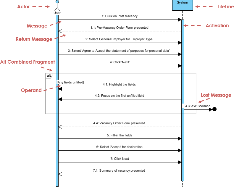
For more details about Sequence Diagram, please read the article What is Sequence Diagram?
What is a Communication Diagram?
Similar to Sequence Diagram, the Communication Diagram is also used to model the dynamic behavior of the use case. When compare to Sequence Diagram, the Communication Diagram is more focused on showing the collaboration of objects rather than the time sequence. They are actually semantically equivalent, so some of the modeling tool such as, Visual Paradigm allows you to generate it from one to the other.
Communication Diagram Example

For more details about Communication Diagram, please read the article What is Communication Diagram?
What is Interaction Overview Diagram?
Interaction overview diagram example.
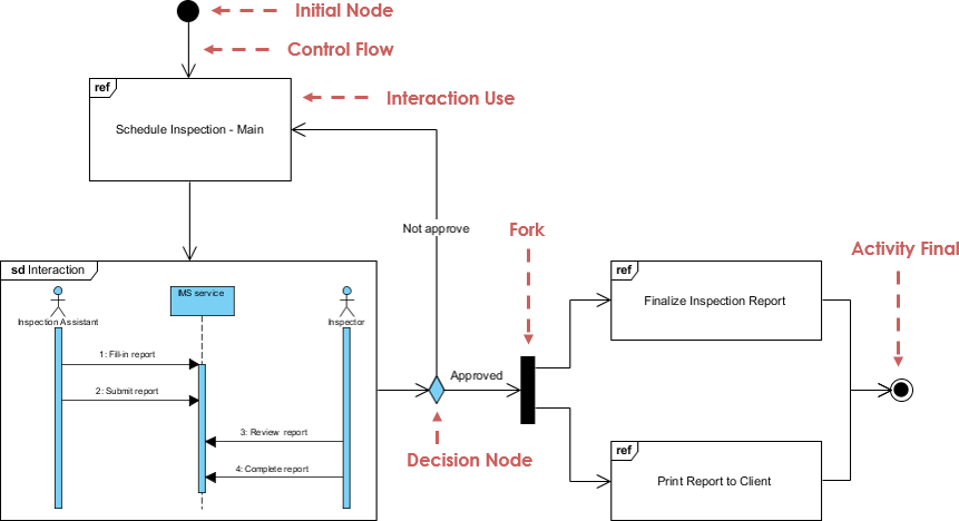
For more details about Interaction Overview Diagram, please read the article What is Interaction Overview Diagram?
What is Timing Diagram?
Timing Diagram shows the behavior of the object(s) in a given period of time. Timing diagram is a special form of a sequence diagram. The differences between timing diagram and sequence diagram are the axes are reversed so that the time are increase from left to right and the lifelines are shown in separate compartments arranged vertically.
Timing Diagram Example

For more details about Timing Diagram, please read the article What is Timing Diagram?
Learn UML. Draw UML.
Get Visual Paradigm Community Edition, a free UML tool that can help you learn UML faster & more effectively. Visual Paradigm Community Edition supports all UML diagram types. Its UML modeler is award-winning, easy-to-use and intuitive.
UML Glossary and Terms
- Abstract Class - A class that will never be instantiated. An instance of this class will never exist.
- Actor - An object or person that initiates events the system is involved with.
- Activity : A step or action within an Activity Diagram. Represents an action taken by the system or by an Actor.
- Activity Diagram : A glorified flowchart that shows the steps and decisions and parallel operations within a process, such as an algorithm or a business process.
- Aggregation - Is a part of another class. Shown with a hollow diamond next to the containing class in diagrams.
- Artifacts - Documents describing the output of a step in the design process. The description is graphic, textual, or some combination.
- Association - A connection between two elements of a Model. This might represent a member variable in code, or the association between a personnel record and the person it represents, or a relation between two categories of workers, or any similar relationship. By default, both elements in an Association are equal, and are aware of each other through the Association. An Association can also be a Navigable Association, meaning that the source end of the association is aware of the target end, but not vice versa.
- Association Class : A Class that represents and adds information to the Association between two other Classes.
- Attributes - Characteristics of an object which may be used to reference other objects or save object state information.
- Base Class : A Class which defines Attributes and Operations that are inherited by a Subclass via a Generalization relationship.
- Branch : A decision point in an Activity Diagram. Multiple Transitions emerge from the Branch, each with a Guard Condition. When control reaches the Branch, exactly one Guard Condition must be true; and control follows the corresponding Transition.
- Class : A category of similar Objects, all described by the same Attributes and Operations and all assignment-compatible.
- Class Diagram - Shows the system classes and relationships between them.
- Classifier : A UML element that has Attributes and Operations. Specifically, Actors, Classes, and Interfaces.
- Collaboration : A relation between two Objects in a Communication Diagram, indicating that Messages can pass back and forth between the Objects.
- Communication Diagram - A diagram that shows how operations are done while emphasizing the roles of objects.
- Component : A deployable unit of code within the system.
- Component Diagram : A diagram that shows relations between various Components and Interfaces.
- Concept - A noun or abstract idea to be included in a domain model.
- Construction Phase - The third phase of the Rational Unified Process during which several iterations of functionality are built into the system under construction. This is where the main work is done.
- Dependence : A relationship that indicates one Classifier knows the Attributes and Operations of another Classifier, but isn't directly connected to any instance of the second Classifier.
- Deployment Diagram : A diagram that shows relations between various Processors.
- Domain -The part of the universe that the system is involved with.
- Elaboration Phase - The second phase of the Rational Unified Process that allows for additional project planning including the iterations of the construction phase.
- Element : Any item that appears in a Model.
- Encapsulation - Data in objects is private.
- Generalization - Indicates that one class is a subclass on another class (superclass). A hollow arrow points to the superclass.
- Event : In a State Diagram, this represents a signal or event or input that causes the system to take an action or switch States.
- Final State : In a State Diagram or an Activity Diagram, this indicates a point at which the diagram completes.
- Fork : A point in an Activity Diagram where multiple parallel control threads begin.
- Generalization : An inheritance relationship, in which a Subclass inherits and adds to the Attributes and Operations of a Base Class.
- GoF - Gang of Four set of design patterns.
- High Cohesion - A GRASP evaluative pattern which makes sure the class is not too complex, doing unrelated functions.
- Low Coupling - A GRASP evaluative pattern which measures how much one class relies on another class or is connected to another class.
- Inception Phase - The first phase of the Rational Unified Process that deals with the original conceptualization and beginning of the project.
- Inheritance - Subclasses inherit the attributes or characterics of their parent (superclass) class. These attributes can be overridden in the subclass.
- Initial State : In a State Diagram or an Activity Diagram, this indicates the point at which the diagram begins.
- Instance - A class is used like a template to create an object. This object is called an instance of the class. Any number of instances of the class may be created.
- Interface : A Classifier that defines Attributes and Operations that form a contract for behavior. A provider Class or Component may elect to Realize an Interface (i.e., implement its Attributes and Operations). A client Class or Component may then Depend upon the Interface and thus use the provider without any details of the true Class of the provider.
- Iteration - A mini project section during which some small piece of functionality is added to the project. Includes the development loop of analysis, design and coding.
- Join : A point in an Activity Diagram where multiple parallel control threads synchronize and rejoin.
- Member : An Attribute or an Operation within a Classifier.
- Merge : A point in an Activity Diagram where different control paths come together.
- Message - A request from one object to another asking the object receiving the message to do something. This is basically a call to a method in the receiving object.
- Method - A function or procedure in an object.
- Model - The central UML artifact. Consists of various elements arranged in a hierarchy by Packages, with relations between elements as well.
- Multiplicity - Shown in a domain model and indicated outside concept boxes, it indicates object quantity relationship to quantiles of other objects.
- Navigability : Indicates which end of a relationship is aware of the other end. Relationships can have bidirectional Navigability (each end is aware of the other) or single directional Navigability (one end is aware of the other, but not vice versa).
- Notation - Graphical document with rules for creating analysis and design methods.
- Note : A text note added to a diagram to explain the diagram in more detail.
- Object - Object: In an Activity Diagram, an object that receives information from Activities or provides information to Activities. In a Collaboration Diagram or a Sequence Diagram, an object that participates in the scenario depicted in the diagram. In general: one instance or example of a given Classifier (Actor, Class, or Interface).
- Package - A group of UML elements that logically should be grouped together.
- Package Diagram : A Class Diagram in which all of the elements are Packages and Dependencies.
- Pattern - Solutions used to determine responsibility assignment for objects to interact. It is a name for a successful solution to a well-known common problem.
- Parameter : An argument to an Operation.
- Polymorphism - Same message, different method. Also used as a pattern.
- Private : A Visibility level applied to an Attribute or an Operation, indicating that only code for the Classifier that contains the member can access the member.
- Processor : In a Deployment Diagram, this represents a computer or other programmable device where code may be deployed.
- Protected : A Visibility level applied to an Attribute or an Operation, indicating that only code for the Classifier that contains the member or for its Subclasses can access the member.
- Public : A Visibility level applied to an Attribute or an Operation, indicating that any code can access the member.
- Reading Direction Arrow - Indicates the direction of a relationship in a domain model.
- Realization : Indicates that a Component or a Class provides a given Interface.
- Role - Used in a domain model, it is an optional description about the role of an actor.
- Sequence Diagram : A diagram that shows the existence of Objects over time, and the Messages that pass between those Objects over time to carry out some behavior. State chart diagram - A diagram that shows all possible object states.
- State : In a State Diagram, this represents one state of a system or subsystem: what it is doing at a point in time, as well as the values of its data.
- State Diagram : A diagram that shows States of a system or subsystem, Transitions between States, and the Events that cause the Transitions.
- Static : A modifier to an Attribute to indicate that there's only one copy of the Attribute shared among all instances of the Classifier. A modifier to an Operation to indicate that the Operation stands on its own and doesn't operate on one specific instance of the Classifier.
- Stereotype : A modifier applied to a Model element indicating something about it which can't normally be expressed in UML. In essence, Stereotypes allow you to define your own "dialect" of UML.
- Subclass : A Class which inherits Attributes and Operations that are defined by a Subclass via a Generalization relationship.
- Swimlane : An element of an Activity Diagram that indicates what parts of a system or a domain perform particular Activities. All Activities within a Swimlane are the responsibility of the Object, Component, or Actor represented by the Swimlane.
- Time Boxing - Each iteration will have a time limit with specific goals.
- Transition : In an Activity Diagram, represents a flow of control from one Activity or Branch or Merge or Fork or Join to another. In a State Diagram, represents a change from one State to another.
- Transition Phase - The last phase of the Rational Unified Process during which users are trained on using the new system and the system is made available to users.
- UML - Unified Modeling Language utilizes text and graphic documents to enhance the analysis and design of software projects by allowing more cohesive relationships between objects.
- Use Case : In a Use Case Diagram, represents an action that the system takes in response to some request from an Actor.
- Use Case Diagram : A diagram that shows relations between Actors and Use Cases.
- Visibility : A modifier to an Attribute or Operation that indicates what code has access to the member. Visibility levels include Public, Protected, and Private.
- Workflow - A set of activities that produces some specific result.
Popular UML Books
Listed below are some of the best selling UML books you can read to learn UML.
- UML Distilled: A Brief Guide to the Standard Object Modeling Language
- UML 2 and the Unified Process: Practical Object-Oriented Analysis and Design
- Learning UML 2.0
- Building Web Applications with UML
- The Unified Modeling Language Reference Manual
- The Elements of UML 2.0 Style
- UML for Java Programmers
- Schaum's Outline of UML
- The Unified Modeling Language User Guide
- UML 2 Certification Guide: Fundamental and Intermediate Exams
- Fundamentals of Object-Oriented Design in UML
- Applying Use Case Driven Object Modeling with UML: An Annotated E-Commerce Example
- Designing Flexible Object Oriented Systems With UML
- Use Case Driven Object Modeling with UML
- Systems Analysis and Design with UML Version 2.0: An Object-Oriented Approach
- UML 2.0 in a Nutshell
- Object-Oriented Analysis and Design with Applications
- UML Explained
- Design Patterns: Elements of Reusable Object-Oriented Software
- The Object Primer: Agile Model-Driven Development with UML 2.0
Related Links
- Professional UML design tool for visual modeling
Turn every software project into a successful one.
We use cookies to offer you a better experience. By visiting our website, you agree to the use of cookies as described in our Cookie Policy .
© 2024 by Visual Paradigm. All rights reserved.
- Privacy statement
Introduction to UML: Unified Modeling Language
Nov 10, 2023
170 likes | 222 Views
This lecture provides an introduction to UML, the Unified Modeling Language. It explains the motivation behind modeling, the concept of systems and views, and the different categories and diagrams used in UML. UML is a standardized graphical language used for specifying, visualizing, constructing, and documenting software systems.
Share Presentation
- unified modeling language
- structure diagrams
- behavior diagrams
- uml history
- class diagram

Presentation Transcript
Lecture 9-1 : Intro. to UML (Unified Modeling Language)
Motivation of Modeling • Realistic and useful systems are large and complex • UNIX system V : 1M SLOC (source lines of code) • Windows2000 : 40M SLOC • Systems require the work of many people • Developers, testers, managers, clients, users, etc • Systems have an extended life cycle, hence they evolve • 1M SLOC with 100 persons ≠ 10k SLOC with 1 person Modeling
Systems, Models, and Views • System • a set of interacting or interdependent entities forming an integrated whole. • subsystem : is a system itself and a part of a larger system • Common characteristics of system : Systems have • Structure • defined by parts and their composition • Behavior • involves inputs, processing and outputs of materials, energy or information • Interconnectivity • the various parts of a system have functional as well as structural relationships between each other
Systems, Models, and Views • Model • Abstraction describing a system (or a subset) • ex) computer model, business model, data model, mathematical model, economic model, …, etc • View • Selected aspects of a model • Notation • Set of rules for representing views • Views and models of a single system can overlap each other
What is UML? • UML → “Unified Modeling Language” • Emerging standard for modeling object-oriented Software • Language: express idea, not a methodology • Modeling: describing a software system at a high level of abstraction • Unified: UML has become a world standard
What is UML? • More description about UML: • It is a industry-standard graphical language for specifying, visualizing, constructing, and documenting the artifacts of software systems • The UML uses mostly graphical notations to express the OO analysis and design of software projects. • Simplifies the complex process of software design
Why we use UML? • Use graphical notation: clearer than natural language (imprecise) and code (too detailed). • Help acquire an overall view of a system. • UML is not dependent on any one language or technology. • UML moves us from fragmentationto standardization. • share idea and the results of system design among clients, system analysts, and programmers
State Diagrams State Diagrams State Diagrams State Diagrams State Diagrams State Diagrams Object Diagrams Component Diagrams Class Diagrams Component Diagrams Component Diagrams Deployment Diagrams Use Case Diagrams Use Case Diagrams Scenario Diagrams Scenario Diagrams Use Case Diagrams Use Case Diagrams Scenario Diagrams Scenario Diagrams Use Case Diagrams Sequence Diagrams Statechart Diagrams Collaboration Diagrams Models, Views, and Diagrams A model is a complete description of a system from a particular perspective Models Activity Diagrams
3 categories of UML diagrams • Structure Diagrams :what things must be in the system being modeled • Class diagram • Component diagram • Composite diagram • Deployment diagram • Object diagram • Package diagram • Behavior Diagrams : what must happen in the system being modeled • Activity diagram • State diagram • Use case diagram • Interaction Diagram (subset of behavior diagram) : the flow of control and data among the things in the system being modeled • Communication diagram • Interaction overview diagram • Sequence diagram • Timing diagram
3 categories of UML diagrams
Year Version Currently UML 2.2 2005: UML 2.0 2001: UML 1.4 1999: UML 1.3 1997: UML 1.0, 1.1 1996: UML 0.9 & 0.91 1995: Unified Method 0.8 OMT - 2 Booch ‘93 Other methods Booch ‘91 OMT - 1 UML History
UML Diagrams • Each graphical notation of UML is used for drawing diagrams • The purpose of diagrams is to provide views from different perspective. • Model is a set of views • We will look at summary of each diagram in the following slides
Class Diagram • Describe the static structure of the system • Objects, attributes, and associations
Use-Case Diagram • shows the functionality provided by a system in terms of actors, their goals represented as use cases, and any dependencies between those use cases
State (Statechart) Diagram • Describe the dynamic behavior of an individual object as a finite state machine.
Sequence Diagram • Describe the dynamic behavior between actors and the system and between objects of the system.
Why so many diagrams? • Multiple aspects of a complex system • Need for detailed analysis and design
- More by User

Introduction to Unified Modeling Language (UML)
Introduction to Unified Modeling Language (UML). By Mercer & Milanova, updated by Professor Spiegel, with help from The Unified Modeling Language User Guide , Grady Booch, James Rumbaugh, Ivar Jacobsen , Addison Wesley, 1999, ISBN 0-201-57168-4. play(). roll(). fv1:=getFaceValue().
754 views • 47 slides

Introduction to UML
Introduction to UML. CS A401. What is UML?. Unified Modeling Language OMG Standard, Object Management Group Based on work from Booch, Rumbaugh, Jacobson UML is a modeling language to express and design documents, software Particularly useful for OO design
996 views • 70 slides

Introduction to UML: Unified Modeling Language. Ric Holt U Waterloo, March 2009 CS246. Example UML Class Diagram. http://www.agiledata.org/images/oo101ClassDiagram.gif. UML: Unified Modeling Language.
571 views • 25 slides
UML Diagrams
UML Diagrams. Computer Science I. Unified Modeling Language. Unified Modeling Language (UML) is a standardized general-purpose modeling language in the field of software engineering. The standard is managed, and was created by, the Object Management Group.
965 views • 51 slides
The Unified Modeling Language (UML) Class Diagrams
The Unified Modeling Language (UML) Class Diagrams. Unified Modeling Language. A standardized modeling language for the conceptualization and design of software systems Two types of diagrams: structure diagram and behavior diagram
306 views • 17 slides

UML. unified modeling language. 1994 first attempts - largely theoretical 1997 UML becomes an industry standard ... ongoing evolution and efforts to standardize 2005 Nov.Dec. version 2.0 2007 Aug. version 2.1. general-purpose visual modeling language
281 views • 7 slides
WELCOME TO OUR PRESENTATION UNIFIED MODELING LANGUAGE (UML)
WELCOME TO OUR PRESENTATION UNIFIED MODELING LANGUAGE (UML). OUTLINES . Introduction. Implementation. - class diagrams - Objects - Activity Diagrams Advantages of UML. Disadvantages of UML. Conclusion. . Introduction. Unified modeling language ( UML ):
580 views • 22 slides
UML Unified Modeling Language
UML Unified Modeling Language. What is UML?. Unified Modeling Language (UML) is a standardized, general-purpose modeling language in the field of software engineering.
486 views • 22 slides

Introduction to Unified Modeling Language (UML). By Rick Mercer with help from The Unified Modeling Language User Guide , Grady Booch, James Rumbaugh, Ivar Jacobsen , Addison Wesley, 1999, ISBN 0-201-57168-4. The Unified Modeling Language (UML).
737 views • 29 slides

Introduction to UML. CSCE A401. What is UML?. Unified Modeling Language OMG Standard, Object Management Group Based on work from Booch, Rumbaugh, Jacobson UML is a modeling language to express and design documents, software Particularly useful for OO design
883 views • 70 slides
Unified Modeling Language (UML)
(Chapter 6). Unified Modeling Language (UML). Unified Modeling Language. UML October 1994 Three Amigos Grady Booch (Rational Software) [Booch] James Rumbaugh (Objectory) [OMT] Ivar Jacobson (General Electric) [OOSE]
561 views • 31 slides

Introduction to Unified Modeling Language (UML). By: Sharraf Hussain. Introduction.
551 views • 38 slides
Intro to UML - OO Class Diagrams
Intro to UML - OO Class Diagrams. Week 5 CMIS570. Plan for Tonight. Object terms Unified Modeling Language history Class Diagrams Intro to Oracle Oracle ERDs. Object-Oriented Analysis & Design. Object-oriented analysis Defines all of the types of objects that do the work of the system
475 views • 28 slides
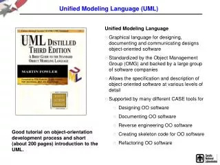
Unified Modeling Language (UML). Unified Modeling Language Graphical language for designing, documenting and communicating designs object-oriented software Standardized by the Object Management Group (OMG) and backed by a large group of software companies
133 views • 2 slides
Lecture 8-1 : Introduction to UML (Unified Modeling Language)
Lecture 8-1 : Introduction to UML (Unified Modeling Language). Motivation of Modeling. Realistic and useful systems are large and complex UNIX system V : 1M SLOC (source lines of code) Windows2000 : 40M SLOC Systems require the work of many people
312 views • 19 slides

UML – Unified Modeling Language
UML – Unified Modeling Language. Use-Case Diagrams. What is UML?. UML unified modeling language Mainly used for development of OO Used in conjunction with UP Unified process. What is UP?. Inception Elaboration Construction Transition Production. What is a use-case diagram?.
314 views • 12 slides

Introduction to UML. CSCE A222. What is UML?. Unified Modeling Language OMG Standard, Object Management Group Based on work from Booch, Rumbaugh, Jacobson UML is a modeling language to express and design documents, software Particularly useful for OO design
723 views • 71 slides

271 views • 25 slides

247 views • 23 slides
Visión general de UML (Unified Modeling Language)
UML o el Unified Modeling Languager r LENGUAJE de propu00f3sito general, ni mu00e9todo, ni metodologu00eda, el mu00e9todo incluye al lenguaje y al proceso:r r Lenguaje de Modelado -> Notaciu00f3n (generalmente gru00e1fica) que utiliza el mu00e9todo para expresarser Proceso -> recomendaciu00f3n sobre que pasos tomar para diseu00f1arr Mu00e9todo -> Lenguaje de Modelado + Proceso
410 views • 40 slides
- What is System Design
- Design Patterns
- Creational Design Patterns
- Structural Design Patterns
- Behavioral Design Patterns
- Design Patterns Cheat Sheet
- Design Patterns Interview Questions
- Design Patterns in Java
- Design Patterns in JavaScript
- Design Patterns in C++
- Design Patterns in Python
Unified Modeling Language (UML) Diagrams
Unified Modeling Language (UML) is a general-purpose modeling language. The main aim of UML is to define a standard way to visualize the way a system has been designed. It is quite similar to blueprints used in other fields of engineering. UML is not a programming language , it is rather a visual language.
-Diagrams.webp)
Understanding and effectively using UML can significantly improve the quality and clarity of your software designs. Our specialized course on System design provides detailed guidance and practical examples to help you master this visual language. By integrating UML into your workflow, you can create more comprehensive and communicative system models.
Important Topics for Unified Modeling Language (UML) Diagrams
- What is UML?
- Why do we need UML?
- Different Types of UML Diagrams
- Structural UML Diagrams
- Behavioral UML Diagrams
- Object-Oriented Concepts Used in UML Diagrams
- Tools for creating UML Diagrams
- Steps to create UML Diagrams
- UML diagrams best practices
- UML and Agile Development
- Common Challenges in UML Modeling
- Benefits of Using UML Diagrams
1. What is UML?
Unified Modeling Language (UML) is a standardized visual modeling language used in the field of software engineering to provide a general-purpose, developmental, and intuitive way to visualize the design of a system. UML helps in specifying, visualizing, constructing, and documenting the artifacts of software systems.
- We use UML diagrams to portray the behavior and structure of a system.
- UML helps software engineers, businessmen, and system architects with modeling, design, and analysis.
- The Object Management Group (OMG) adopted Unified Modelling Language as a standard in 1997. It’s been managed by OMG ever since.
- The International Organization for Standardization (ISO) published UML as an approved standard in 2005. UML has been revised over the years and is reviewed periodically.
2. Why do we need UML?
- Complex applications need collaboration and planning from multiple teams and hence require a clear and concise way to communicate amongst them.
- Businessmen do not understand code. So UML becomes essential to communicate with non-programmers about essential requirements, functionalities, and processes of the system.
- A lot of time is saved down the line when teams can visualize processes, user interactions, and the static structure of the system.
3. Different Types of UML Diagrams
UML is linked with object-oriented design and analysis. UML makes use of elements and forms associations between them to form diagrams. Diagrams in UML can be broadly classified as:

4. Structural UML Diagrams
4.1. class diagram.
The most widely use UML diagram is the class diagram. It is the building block of all object oriented software systems. We use class diagrams to depict the static structure of a system by showing system’s classes, their methods and attributes. Class diagrams also help us identify relationship between different classes or objects.
4.2. Composite Structure Diagram
We use composite structure diagrams to represent the internal structure of a class and its interaction points with other parts of the system.
- A composite structure diagram represents relationship between parts and their configuration which determine how the classifier (class, a component, or a deployment node) behaves.
- They represent internal structure of a structured classifier making the use of parts, ports, and connectors.
- We can also model collaborations using composite structure diagrams.
- They are similar to class diagrams except they represent individual parts in detail as compared to the entire class.
4.3. Object Diagram
An Object Diagram can be referred to as a screenshot of the instances in a system and the relationship that exists between them. Since object diagrams depict behaviour when objects have been instantiated, we are able to study the behaviour of the system at a particular instant.
- An object diagram is similar to a class diagram except it shows the instances of classes in the system.
- We depict actual classifiers and their relationships making the use of class diagrams.
- On the other hand, an Object Diagram represents specific instances of classes and relationships between them at a point of time.
4.4. Component Diagram
Component diagrams are used to represent how the physical components in a system have been organized. We use them for modelling implementation details.
- Component Diagrams depict the structural relationship between software system elements and help us in understanding if functional requirements have been covered by planned development.
- Component Diagrams become essential to use when we design and build complex systems.
- Interfaces are used by components of the system to communicate with each other.
4.5. Deployment Diagram
Deployment Diagrams are used to represent system hardware and its software.It tells us what hardware components exist and what software components run on them.
- We illustrate system architecture as distribution of software artifacts over distributed targets.
- An artifact is the information that is generated by system software.
- They are primarily used when a software is being used, distributed or deployed over multiple machines with different configurations.
4.6. Package Diagram
We use Package Diagrams to depict how packages and their elements have been organized. A package diagram simply shows us the dependencies between different packages and internal composition of packages.
- Packages help us to organise UML diagrams into meaningful groups and make the diagram easy to understand.
- They are primarily used to organise class and use case diagrams.
5. Behavioral UML Diagrams
5.1. state machine diagrams.
A state diagram is used to represent the condition of the system or part of the system at finite instances of time. It’s a behavioral diagram and it represents the behavior using finite state transitions.
- State diagrams are also referred to as State machines and State-chart Diagrams
- These terms are often used interchangeably. So simply, a state diagram is used to model the dynamic behavior of a class in response to time and changing external stimuli.
5.2. Activity Diagrams
We use Activity Diagrams to illustrate the flow of control in a system. We can also use an activity diagram to refer to the steps involved in the execution of a use case.
- We model sequential and concurrent activities using activity diagrams. So, we basically depict workflows visually using an activity diagram.
- An activity diagram focuses on condition of flow and the sequence in which it happens.
- We describe or depict what causes a particular event using an activity diagram.
5.3. Use Case Diagrams
Use Case Diagrams are used to depict the functionality of a system or a part of a system. They are widely used to illustrate the functional requirements of the system and its interaction with external agents(actors).
- A use case is basically a diagram representing different scenarios where the system can be used.
- A use case diagram gives us a high level view of what the system or a part of the system does without going into implementation details.
5.4. Sequence Diagram
A sequence diagram simply depicts interaction between objects in a sequential order i.e. the order in which these interactions take place.
- We can also use the terms event diagrams or event scenarios to refer to a sequence diagram.
- Sequence diagrams describe how and in what order the objects in a system function.
- These diagrams are widely used by businessmen and software developers to document and understand requirements for new and existing systems.
5.5. Communication Diagram
A Communication Diagram (known as Collaboration Diagram in UML 1.x) is used to show sequenced messages exchanged between objects.
- A communication diagram focuses primarily on objects and their relationships.
- We can represent similar information using Sequence diagrams, however communication diagrams represent objects and links in a free form.
5.6. Timing Diagram
Timing Diagram are a special form of Sequence diagrams which are used to depict the behavior of objects over a time frame. We use them to show time and duration constraints which govern changes in states and behavior of objects.
5.7. Interaction Overview Diagram
An Interaction Overview Diagram models a sequence of actions and helps us simplify complex interactions into simpler occurrences. It is a mixture of activity and sequence diagrams.
6. Object-Oriented Concepts Used in UML Diagrams
- Class: A class defines the blue print i.e. structure and functions of an object.
- Objects : Objects help us to decompose large systems and help us to modularize our system. Modularity helps to divide our system into understandable components so that we can build our system piece by piece.
- Inheritance: Inheritance is a mechanism by which child classes inherit the properties of their parent classes.
- Abstraction: Abstraction in UML refers to the process of emphasizing the essential aspects of a system or object while disregarding irrelevant details. By abstracting away unnecessary complexities, abstraction facilitates a clearer understanding and communication among stakeholders.
- Encapsulation: Binding data together and protecting it from the outer world is referred to as encapsulation.
- Polymorphism: Mechanism by which functions or entities are able to exist in different forms.
6.1. Additions in UML 2.0
- Software development methodologies like agile have been incorporated and scope of original UML specification has been broadened.
- Originally UML specified 9 diagrams. UML 2.x has increased the number of diagrams from 9 to 13. The four diagrams that were added are : timing diagram, communication diagram, interaction overview diagram and composite structure diagram. UML 2.x renamed statechart diagrams to state machine diagrams.
- UML 2.x added the ability to decompose software system into components and sub-components.
7. Tools for creating UML Diagrams
There are several tools available for creating Unified Modeling Language (UML) diagrams, which are commonly used in software development to visually represent system architecture, design, and implementation. Here are some popular UML diagram creating tools:
- Lucidchart: Lucidchart is a web-based diagramming tool that supports UML diagrams. It’s user-friendly and collaborative, allowing multiple users to work on diagrams in real-time.
- Draw.io: Draw.io is a free, web-based diagramming tool that supports various diagram types, including UML. It integrates with various cloud storage services and can be used offline.
- Visual Paradigm: Visual Paradigm provides a comprehensive suite of tools for software development, including UML diagramming. It offers both online and desktop versions and supports a wide range of UML diagrams.
- StarUML: StarUML is an open-source UML modeling tool with a user-friendly interface. It supports the standard UML 2.x diagrams and allows users to customize and extend its functionality through plugins.
- Papyrus: Papyrus is an open-source UML modeling tool that is part of the Eclipse Modeling Project. It provides a customizable environment for creating, editing, and visualizing UML diagrams.
- PlantUML: PlantUML is a text-based tool that allows you to create UML diagrams using a simple and human-readable syntax. It’s often used in conjunction with other tools and supports a variety of diagram types.
8. Steps to create UML Diagrams

Creating Unified Modeling Language (UML) diagrams involves a systematic process that typically includes the following steps:
- Determine the purpose of creating the UML diagram. Different types of UML diagrams serve various purposes, such as capturing requirements, designing system architecture, or documenting class relationships.
- Identify the key elements (classes, objects, use cases, etc.) and their relationships that need to be represented in the diagram. This step involves understanding the structure and behavior of the system you are modeling.
- Choose the UML diagram type that best fits your modeling needs. Common types include Class Diagrams, Use Case Diagrams, Sequence Diagrams, Activity Diagrams, and more.
- Before using a UML modeling tool, it can be helpful to create a rough sketch on paper or a whiteboard. This can help you visualize the layout and connections between elements.
- Select a UML modeling tool that suits your preferences and requirements. There are various tools available, both online and offline, that offer features for creating and editing UML diagrams.
- Open the selected UML modeling tool and create a new project or diagram. Begin adding elements (e.g., classes, use cases, actors) to the diagram and connect them with appropriate relationships (e.g., associations, dependencies).
- For each element in the diagram, specify relevant properties and attributes. This might include class attributes and methods, use case details, or any other information specific to the diagram type.
- Enhance the clarity of your diagram by adding annotations, comments, and explanatory notes. This helps anyone reviewing the diagram to understand the design decisions and logic behind it.
- Review the diagram for accuracy and completeness. Ensure that the relationships, constraints, and elements accurately represent the intended system or process. Validate your diagram against the requirements and make necessary adjustments.
- Refine the diagram based on feedback and additional insights. UML diagrams are often created iteratively as the understanding of the system evolves.
- Some UML tools allow you to generate documentation directly from your diagrams. This can include class documentation, use case descriptions, and other relevant information.
Note: Remember that the specific steps may vary based on the UML diagram type and the tool you are using.
9. UML diagrams best practices
Unified Modeling Language (UML) is a powerful tool for visualizing and documenting the design of a system. To create effective and meaningful UML diagrams, it’s essential to follow best practices. Here are some UML best practices:
- Understand the Audience: Consider your audience when creating UML diagrams. Tailor the level of detail and the choice of diagrams to match the understanding and needs of your audience, whether they are developers, architects, or stakeholders.
- Keep Diagrams Simple and Focused: Aim for simplicity in your diagrams. Each diagram should focus on a specific aspect of the system or a particular set of relationships. Avoid clutter and unnecessary details that can distract from the main message.
- Use Consistent Naming Conventions: Adopt consistent and meaningful names for classes, objects, attributes, methods, and other UML elements. Clear and well-thought-out naming conventions enhance the understandability of your diagrams.
- Follow Standard UML Notations: Adhere to standard UML notations and symbols. Consistency in using UML conventions ensures that your diagrams are easily understood by others who are familiar with UML.
- Keep Relationships Explicit: Clearly define and label relationships between elements. Use appropriate arrows, multiplicity notations, and association names to communicate the nature of connections between classes, objects, or use cases.
10. UML and Agile Development
Unified Modeling Language (UML) and Agile development are two different approaches to software development, and they can be effectively integrated to enhance the overall development process. Here are some key points about the relationship between UML and Agile development:
10.1. UML in Agile Development
- Visualization and Communication: UML diagrams provide a visual way to represent system architecture, design, and behavior. In Agile development, where communication is crucial, UML diagrams can serve as effective communication tools between team members, stakeholders, and even non-technical audiences.
- User Stories and Use Cases: UML use case diagrams can be used to capture and model user stories in Agile development. Use cases help in understanding the system from an end-user perspective and contribute to the creation of user stories.
- Iterative Modeling: Agile methodologies emphasize iterative development, and UML can be adapted to support this approach. UML models can be created and refined incrementally as the understanding of the system evolves during each iteration.
- Agile Modeling Techniques: Agile modeling techniques, such as user story mapping and impact mapping, complement UML by providing lightweight ways to visualize and communicate requirements and design. These techniques align with the Agile principle of valuing working software over comprehensive documentation.
10.2. Balancing Agility and Modeling
- Adaptive Modeling: Adopt an adaptive modeling approach where UML is used to the extent necessary for effective communication and understanding. The focus should be on delivering value through working software rather than exhaustive documentation.
- Team Empowerment: Empower the development team to choose the right level of modeling based on the project’s needs. Team members should feel comfortable using UML as a communication tool without feeling burdened by excessive modeling requirements.
11. Common Challenges in UML Modeling
- Time-Intensive: UML modeling can be perceived as time-consuming, especially in fast-paced Agile environments where rapid development is emphasized. Teams may struggle to keep up with the need for frequent updates to UML diagrams.
- Over-Documentation: Agile principles value working software over comprehensive documentation. There’s a risk of over-documentation when using UML, as teams may spend too much time on detailed diagrams that do not directly contribute to delivering value.
- Changing Requirements: Agile projects often face changing requirements, and UML diagrams may become quickly outdated. Keeping up with these changes and ensuring that UML models reflect the current system state can be challenging.
- Collaboration Issues: Agile emphasizes collaboration among team members, and sometimes UML diagrams are seen as artifacts that only certain team members understand. Ensuring that everyone can contribute to and benefit from UML models can be a challenge.
12. Benefits of Using UML Diagrams
- Standardization: UML provides a standardized way of representing system models, ensuring that developers and stakeholders can communicate using a common visual language.
- Communication: UML diagrams serve as a powerful communication tool between stakeholders, including developers, designers, testers, and business users. They help in conveying complex ideas in a more understandable manner.
- Visualization: UML diagrams facilitate the visualization of system components, relationships, and processes. This visual representation aids in understanding and designing complex systems.
- Documentation: UML diagrams can be used as effective documentation tools. They provide a structured and organized way to document various aspects of a system, such as architecture, design, and behavior.
- Analysis and Design: UML supports both analysis and design phases of software development. It helps in modeling the requirements of a system and then transforming them into a design that can be implemented.
Please Login to comment...
Similar reads.
- Design Pattern
- System Design
- How to Get a Free SSL Certificate
- Best SSL Certificates Provider in India
- Elon Musk's xAI releases Grok-2 AI assistant
- What is OpenAI SearchGPT? How it works and How to Get it?
- Full Stack Developer Roadmap [2024 Updated]
Improve your Coding Skills with Practice
What kind of Experience do you want to share?
The ultimate guide to UML diagrams
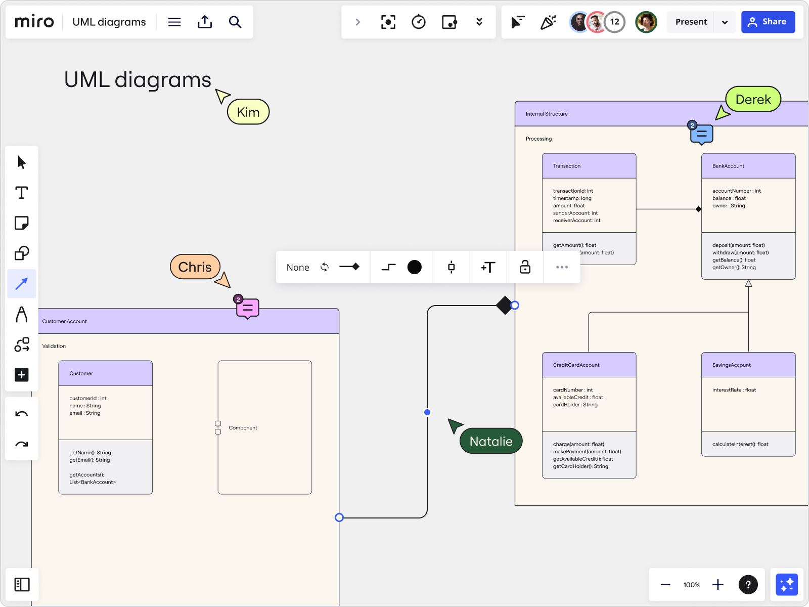
Table of Contents
If you’re familiar with software design, you’ve probably already come across UML diagrams — but what exactly are they, who are they for, and how do you go about making one? We’ve put this quick guide together to answer both these questions and more, covering everything you need to know about UML diagrams. Let’s get to it!
What is a UML diagram?
What is a UML diagram? A UML diagram is a way to visualize systems and software using Unified Modeling Language (UML). Software engineers create UML diagrams to understand the designs, code architecture, and proposed implementation of complex software systems. UML diagrams are also used to model workflows and business processes. Coding can be a complicated process with many interrelated elements. There are often thousands of lines of programming language that can be difficult to understand at first glance. A UML diagram simplifies this information into a visual reference that’s easier to digest. It uses a standardized method for writing a system model and capturing conceptual ideas.
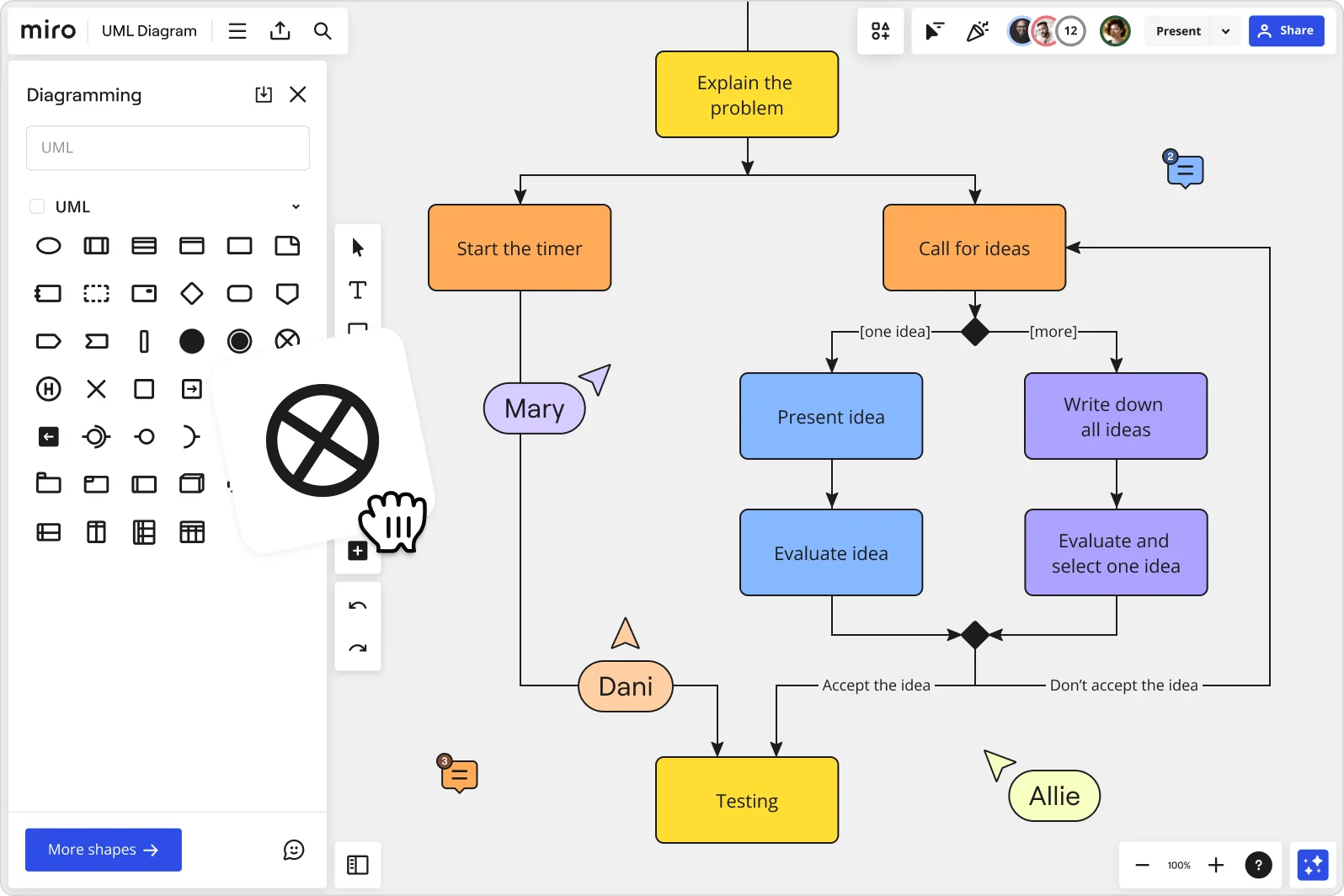
Beyond code, UML diagrams are also great for visualizing relationships and hierarchies within software components, similar to decision trees or flowcharts — but specific to software.
By making complex systems easier to grasp, UML diagrams help engineers and non-technical team members alike track project progress and communicate effectively throughout the software development process. They break down software into essential parts and make it easier to understand how everything fits together.
Types of UML diagrams
There are two subcategories of UML diagrams: structural diagrams and behavioral diagrams.
Structural diagrams visualize the components that make up a system and the relationship between them — showing the static aspects of a system. Behavioral diagrams , on the other hand, represent what happens within a system — including how the components interact with each other and with other systems or users.
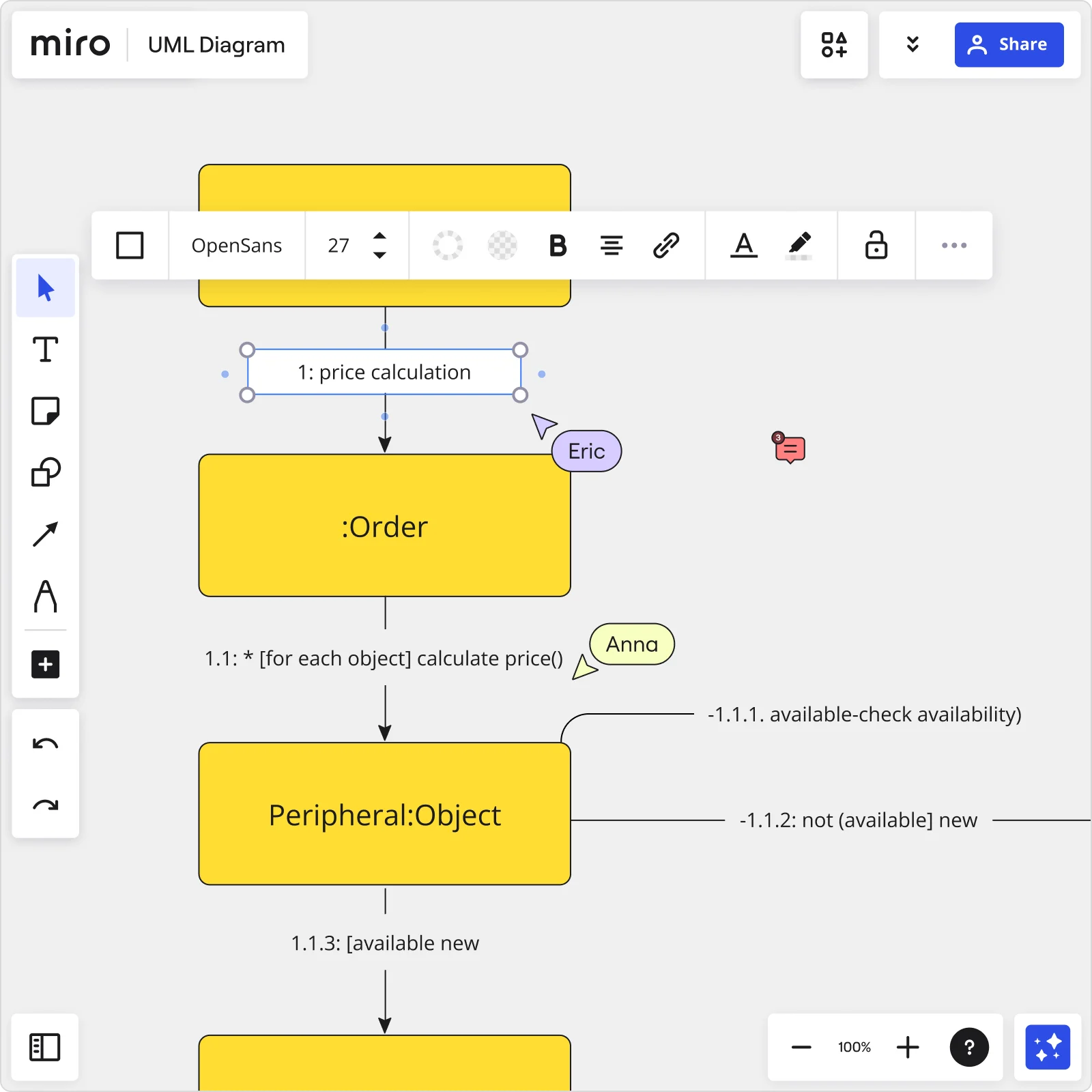
Structural diagrams
Let’s take a look at a few specific types of structural UML diagrams.

Class diagram
A UML class diagram is important for object-oriented design, visually representing the static structure of a system. It shows classes, their attributes, operations, and relationships using rectangles. For instance, software engineers and business stakeholders use these diagrams to visualize the structure and interactions within a software application.
You can easily create these diagrams using a UML class diagram tool .
Package diagram
A package diagram organizes and shows dependencies between packages, which can contain various elements like classes, use cases, and other packages. Think of it as organizing different parts of a system into folders, making it easier to manage and understand the overall architecture.
Object diagram
Object diagrams visualize specific instances of objects and their relationships at a particular moment in time. They typically use real-world examples. In fact, they’re also known as instance diagrams because they display what the system looks like at a specific moment in time.
Component diagram
Component diagrams visualize the internal structure of a class, including its parts, interfaces, and collaborations. They provide insights into how components interact within the larger system architecture, helping to understand the organization and dependencies of software elements.
You can easily create one using a user-friendly UML component diagram tool .
Deployment diagram
Deployment diagrams visualize the physical deployment of software components across nodes in a distributed system. They show how software and hardware interact and are essential for planning and visualizing system deployments in various environments.
Composite structure diagram
Composite structure diagrams visualize the internal structure of a class, including its parts, interfaces, and collaborations. They provide insights into how components interact within the larger system architecture, helping to understand the organization and dependencies of software elements.
Behavioral diagrams
Let’s take a look at some specific examples of behavioral UML diagrams.
Activity diagram
Activity diagrams are essentially flowcharts that visualize the flow of activities within a system. They depict the sequence of actions, decision points, and concurrent activities, making them useful for modeling business processes and system behaviors.
Using an intuitive UML activity diagram maker is the best way to create these diagrams.
Sequence diagram
UML sequence diagrams show how objects interact over time, visualizing the order of messages exchanged between objects. They are particularly effective in illustrating the dynamic interactions between different components in a system.
Developers and business professionals often use sequence diagrams to understand how to structure a new system or improve an existing process. You can easily create them using an online UML sequence diagram .
Communication diagram
Similar to sequence diagrams, communication diagrams focus on the messages exchanged between objects to achieve specific functionalities. They provide a broader view of system interactions and collaborations between objects, facilitating communication and understanding among stakeholders.
You can easily create one using a powerful yet user-friendly communication diagram tool .
Interaction overview diagram
Interaction overview diagrams combine elements of activity and sequence diagrams to provide a high-level view of system interactions. They use frames to represent activities and interactions, offering a comprehensive perspective on system dynamics and workflows.
Timing diagram
Timing diagrams visualize the behavior of objects within specific time frames, showing the timing and duration of events and interactions. They’re helpful for understanding the timing constraints and performance aspects of system operations.
Use case diagram
Use case diagrams visualize the interactions between actors (users or systems) and use cases (functional requirements) within a system. They provide a graphical overview of system functionality and help stakeholders understand the relationships and dependencies between different use cases.
You can easily visualize these interactions using a use case diagram tool .
State machine diagram
State machine diagrams model the behavior of objects as they move through states in response to events. They visualize state transitions, actions, and conditions, providing insights into how components behave in different scenarios. Miro’s state diagram tool makes it easy to create a state chart .
Benefits of UML diagrams
There are plenty of advantages to using UML diagrams — from improving a software engineer’s workflow to streamlining cross-team communication. Let’s take a look at all the benefits:
1. Simplifies complex ideas and systems
UML diagrams visually simplify abstract ideas and complex software systems, making collaboration among software engineers easier. They also help non-technical stakeholders understand system functionality.
2. Visualizes complex code
Turning complicated lines of code into visual diagrams makes software development more straightforward. UML diagrams give a clear picture of how code parts relate and work together, saving time and reducing confusion.
3. Keeps developers on the same page
UML is a standard visual language that helps team members across different languages and stages of development communicate better. It acts as a common guide, making sure everyone understands how the system is designed and progressing.
4. Provides a big-picture view
During the software development process, having a UML diagram to refer to helps developers stay focused on the overarching design and project goals. It’s like having a blueprint that helps you figure out your next step in case you get stuck — all while reminding you of the overall goal anytime you find yourself getting lost in the details.
5. Great for non-technical explanations
Apart from helping software engineers, UML diagrams help product owners, managers, and stakeholders understand software processes and functionalities. They bridge the gap between technical and non-technical team members, promoting better teamwork.
6. Improves cross-team collaboration
Not all programmers understand and specialize in the same type of code and programming languages. Using a standard notation, UML diagrams enable programmers with different skills to work together effectively.
When to use a UML diagram
UML diagrams are great for visualizing complex systems in various settings — both for software and in other scenarios. Let's take a look at two common use cases for UML diagrams:
Software development
You already know that UML diagrams are useful for software development, but they’re especially handy for tackling large-scale projects with intricate architectures. For example, when starting a new software project, teams use UML diagrams to sketch out the system's blueprint.
This helps define how different parts of the software will interact and ensures everyone on the team is on the same page from the start.
Business management
When it comes to managing businesses, UML diagrams have become increasingly valuable for streamlining operations and gaining insights. For example, in startups, these diagrams can map out customer journeys, helping to refine products and enhance user experiences.
Similarly, in larger corporations, UML diagrams are used to visualize complex processes like supply chain management or ERP systems, helping to maintain seamless integration and alignment across departments.
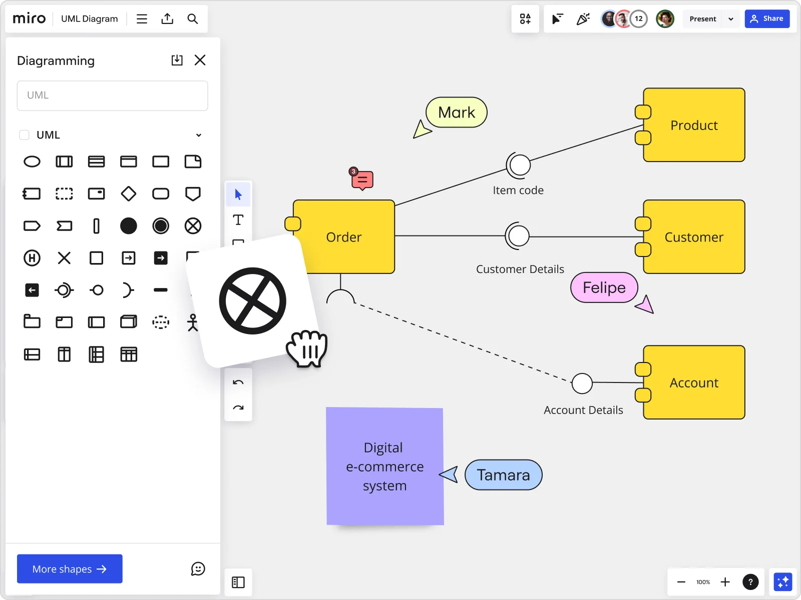
Best practices for creating a UML diagram
There are several best practices that’ll help you create clear and effective UML diagrams without having to overcomplicate the process. Here are some tips to keep in mind:
1. Start with a template
Creating a UML diagram from scratch can seem daunting, especially if it’s your first time. Using pre-made diagramming templates can save you time and ensure you aren’t missing any important diagram components.
Templates also give you an excellent starting point that you can build on. Over time, you can adapt the template to suit your specific needs and requirements.
Miro has tons of customizable UML diagramming templates to help you kickstart your visuals:
UML Diagram Template
UML Activity Diagram Template
UML State Machine Diagram Template
UML Class Diagram Template
UML Component Diagram Template
UML Communication Diagram Template
UML Use Case Diagram Template
2. Have a clear goal
Having a clear goal can set any project up for success, but given that there are so many different types of UML diagrams, it’s especially important in this case. Knowing what you’re trying to achieve can help you choose the right UML diagram to create, which also sets you up for achieving the best possible results.
3. Get team input
One of the main goals of a UML diagram is to make things easier for teams to understand. But just visualizing the software isn’t always enough to communicate your ideas. It’s also a good idea to share your UML diagrams with your team and get feedback — gives all relevant team members an opportunity to add their input.
Getting feedback early on also helps reduce any chances of misalignment along the way or even having to make major changes down the line. Miro’s UML diagramming tool is built for seamless team collaboration — regardless of whether your team connects in person, remotely, in real time, or async.
Create your UML diagram in Miro
Ready to create a UML diagram? Miro is the perfect place to get started. Between our powerful diagramming tools, time-saving UML templates, and seamless collaboration features, you’ll have everything you need to visualize complex systems and keep your team on the same page.
But don’t just take our word for it. Why not see for yourself?
Sign up for Miro to start creating your UML diagram.
Discover more
A guide to UML state machine diagrams
UML component diagrams: learn all you need to know
Understanding UML class diagrams
UML Sequence diagrams: Read all about it in our guide
A guide to understanding UML activity diagrams
What is a UML deployment diagram?
UML diagram examples
Get on board in seconds
Join thousands of teams using Miro to do their best work yet.

Create a UML sequence diagram
A UML sequence diagram shows how a set of objects interact in a process over time . It shows the messages that pass between participants and objects in the system, and the order in which they occur.
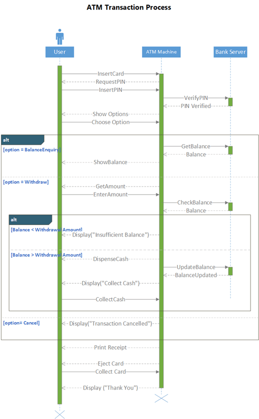
To build a sequence diagram, use a UML Sequence template or starter diagram, which includes the UML Sequence stencil. Drag shapes from the stencil onto the drawing canvas to build the diagram.
Start a sequence diagram
Start Visio. Or if you have a file open already, select File > New .
In the Search box, type UML sequence .
Select the UML Sequence diagram.
In the dialog box, select the blank template or one of the three starter diagrams. (A description of each one is shown on the right when you select it.) Then select either Metric Units or US Units .
Select Create .
The diagram opens. You should see the Shapes window next to the diagram. If you don’t see it, go to View > Task Panes and make sure that Shapes is selected. If you still don’t see it, select the Expand the Shapes window button on the left.
On the View tab, make sure the check box next to Connection Points is selected. This option makes connection points appear when you start connecting shapes.
Now, drag shapes you want to include in your diagram from the Shapes window to the page. To rename text labels, double-click the labels.
Lifelines for actors and objects
Use an Actor lifeline shape for each participant, and an Object lifeline shape for each system component in your process.
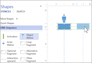
Tip: As you drag the lifelines into place, green alignment guides appear onscreen to help you line up and space the lifelines relative to the other lifeline shapes.
Double-click in the heading box for each lifeline to enter a name or title.
To lengthen or shorten a timeline, select the lifeline, then drag the yellow control point at the bottom of the lifeline.
Use message shapes to represent information being sent between lifelines.
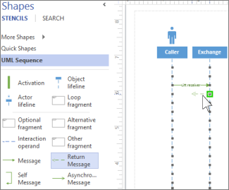
Tip: Visio helps you glue the message endpoints to each lifeline. A green circle appears at the endpoint when it glues to a connection point. The connections points disappear when you are done dragging.
Attach the beginning endpoint to the lifeline sending the message, then drag the head endpoint to the lifeline receiving the message.
Double-click the message shape to create a text box, and type a name for the message.
Use a Message shape (a solid line) to represent a request or the transmitting of information.
Use a Return Message shape (a dashed line) to represent a response to a prior message.
Use a Self Message to represent a recursive call of an operation, or one method calling another method belonging to the same object.
Use the Asynchronous Message shape to show when an action might not happen immediately.
To change the shape of a connector message:
Right-click the connector.
At the bottom of the pop-up menu, select from the three options ( Right-Angle , Straight , Curved ).
Select and drag the connector to change its shape.
If one or more interactions form a loop, or require a condition to be met to end the interaction, enclose those interactions in a fragment shape:
Use the Loop fragment for a basic repeating interaction.
Use the Optional fragment for steps that are only performed if a certain condition is met.
Use the Alternative fragment shape for an if-then or if-then-else process or interaction. The fragment comes with two sections, which let you show the alternative interaction. To add another condition, drag an Interaction operand onto the shape.

Drag the fragment shape to the interactions it relates to. Use the sizing handles on the fragment shape to ensure it encloses all of the related interactions.
Double-click in the title corner of the fragment shape to add a title or short description of the process enclosed by the fragment. Below the title corner, select the [parameters] prompt if you want to enter the conditions that would end that process.
Place an Activation bar shape on a lifeline to show when and for how long that object or participant is active in the process. Typically, there will be arrows going to and from an activation box to demonstrate the flow of information.
Drag the endpoints of the Activation bar up or down to make it the length that you want.
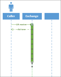
Destruction
Destruction indicates when an object or actor is done participating in a system. A large X appears at the end of its lifeline. To show destruction of an object in a diagram:
Right-click the object, and select Show Destruction .
Note: Creating and editing UML diagrams on Visio for the web requires a Visio Plan 1 or Visio Plan 2 license , which is purchased separately from Microsoft 365. For more information, contact your Microsoft 365 admin . If your admin has turned on "self-service purchasing," you can buy a license for Visio yourself. For more details, see Self-service purchase FAQ .
Open Visio for the web .
Near the upper right corner of the page, select More templates .
In the Gallery, scroll down to the UML Sequence row.
The first item in the row represents a blank template plus the companion stencil. The other items in the row are sample diagrams that have some shapes already drawn to help you get started quickly.
Select any item to see a larger preview.
When you find the diagram you want to use, select its Create button.
The new diagram, with the related stencil, opens in your browser.
Double-click in the title corner of the fragment shape to add a title or short description of the process enclosed by the fragment. Below the title corner, select the [parameters] prompt if you want to enter the conditions that would end that process.
UML diagrams in Visio
Create a UML component diagram
Create a UML communication diagram
Create a UML deployment diagram

Need more help?
Want more options.
Explore subscription benefits, browse training courses, learn how to secure your device, and more.

Microsoft 365 subscription benefits

Microsoft 365 training

Microsoft security

Accessibility center
Communities help you ask and answer questions, give feedback, and hear from experts with rich knowledge.

Ask the Microsoft Community

Microsoft Tech Community

Windows Insiders
Microsoft 365 Insiders
Was this information helpful?
Thank you for your feedback.
How to Make a UML Diagram Online in Minutes?

7 Useful Methods to Create UML Diagrams
- Visual Studio
- MySQL Workbench
Create UML diagram online (GitMind)
The first solution we have here is GitMind. This is a free online mind mapping and collaboration tool that can be used conveniently. This tool can help users to create a mind map, flowchart, organization chart, swimlane, analysis, and even UML diagram. Aside from that, it also offers hundreds of editable templates that you can use for education, business, product, engineering, sales, operations, and others. Moreover, if you want to create your own UML diagram, you can do so. So here are the steps you can follow on how to make a UML diagram.
- The first thing you need to do is to go on your favorite browser and visit the official page of the tool. From here, you will see the “Get Started” button then click it.
- Hit the “UML” option at the left side of the page, and choose the desired template to use. If you wish to create a new flowchart, simply click the “New Flowchart”.
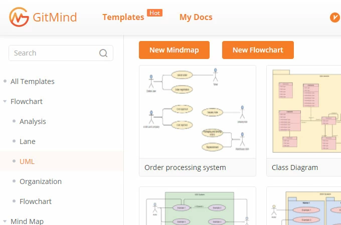
- You will find the shapes and symbols on the left side of the tool, choose the shape or symbol you need then place the cursor on the canvas then start to draw.
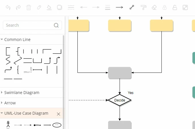
- Customize the diagram depending on your need, then save or export it when you are done.
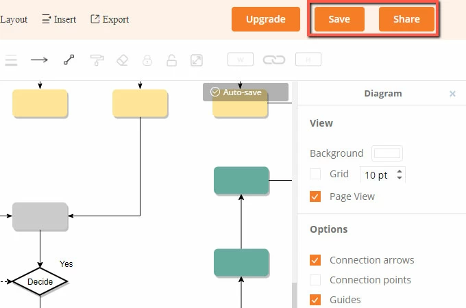
Create UML diagram in Visio
Another way to draw UML diagrams is by using Visio. This is another web-based program that allows you to draw a different variety of diagrams which include UML diagrams, flowcharts, 3D maps, and many more. In addition to that, it offers a wide range of built-in shapes, objects, and stencils. In fact, you can create your own shapes and use them on your diagram. To utilize this software, see the steps given below.
- Open the tool on your favorite browser.
- In the gallery, scroll down the UML class row, you can select a blank template or use the sample diagrams given and edit the content to create a UML diagram.
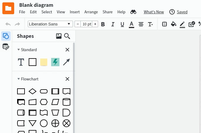
- When you are done, save the diagram.
Create UML diagram in PowerPoint
PowerPoint is one of the popular presentation software which is commonly used by business people and students to create slides for presentations. in addition to that, users can add different content such as diagrams, pie charts, images, and other shapes and symbols. With that, you can create a UML diagram in just a few clicks. Here is the guide on how you can do it.
- Launch the software on your computer then, hit “New blank presentation”.
- Next, hit the “Insert’ options and click shapes to add shapes and other symbols that need to add to your diagram. Edit the diagram according to the information needed.
- When you are done, save the diagram by clicking the “File” then “Save”.
Create UML diagram in Word
An alternative way to draw UML diagrams is by using Word. This software is created by Microsoft similar to PowerPoint. This is a great tool to create a document that is needed for businesses and schools. It can be a letter, resume, catalog, certificates, receipts, report or paper, proposal, and a lot more. Aside from these, users can make a UML diagram, flowchart, and a lot more. See the steps listed below on how this tool works.
- Open a blank Word document to start your UML diagram.
- Click “Insert” then “Text Box” and hit the “Simple Text Box” then edit the text. Enter the name of the classes and other class components. Insert other shapes and symbols for your diagram.
- Once you are finished, save it.
Create UML diagram in Visual Studio
Next on the list in Visual Studio. This is commonly used to develop computer programs, websites, web services, web apps, and even mobile apps. In addition to that, it enables you to create, design, and edit UML diagrams and other types of diagrams. Follow the guide below.
- Open the software and go to the “Solution Explorer” and right-click the project node then choose “Add New Item”.
- From here, click the “Common Items” then “General” and choose the template for your diagram. You can drag shapes, symbols, and lines to the diagram.
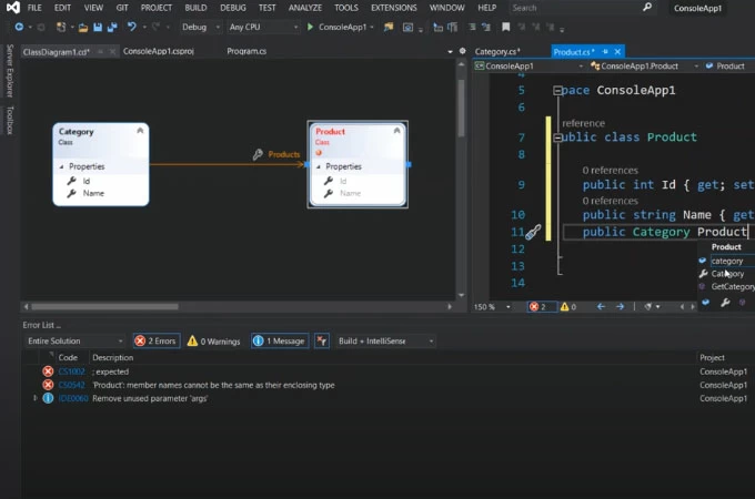
- Once all set, save the diagram.
Create UML diagram in Eclipse
Eclipse is mostly written in Java and it is used for developing Java applications. It can also use to develop applications in other languages. Aside from that, it is also used to create a UML project for any Java project. Below are the simple steps you can follow to create a UML diagram.
- Launch the Eclipse software the choose the java project you wish to create a UML project. Right-click the project and select “Open Visual Paradigm” from the Menu.
- Select the “Project Structure” and choose “Create in a default path”.
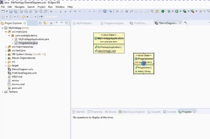
- After that, hit the “OK” button.
Create UML diagram in MySQL Workbench
Last but definitely not least is the MySQL Workbench. This is a visual tool that can be used by developers and database architects that provides data modeling, user administration, and a lot more. Besides, it is very helpful to have a visual representation when you are designing a database. With this tool, you can create a UML diagram from a downloaded SQL file. Here are the steps that you can follow.
- Open the MySQL Workbench then choose “File’ and “New Model” from the top menu. Next, click “File” and “Import” and click ‘Reverse Engineer MySQL Create Script”.
- Specify the SQL file you need then arrange and connect the tables depending on your liking.
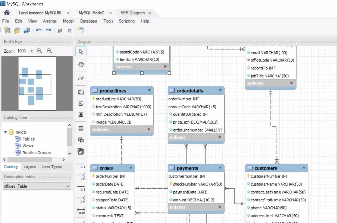
- When you’re done editing, export the diagram.
All the mentioned tools above can surely help you create a UML diagram with ease. You can try all these solutions however, if you are into practicality, choose GitMind since it is very convenient and free to use.
Related posts:
- Best 8 Free Online UML diagram tools in 2024
- What is A Probability Tree Diagram and Real Life Uses
Leave a Comment
Comment (0).
This website uses cookies that are essential for the operations of this website and its core functions. Other cookies will only be placed with your consent. For more details visit our Cookies Policy .
Qu'est-ce que le langage UML (langage de modélisation unifié) ?
Quels sont vos besoins en matière de création de diagrammes uml , je souhaite créer mon propre diagramme uml dans lucidchart., je souhaite créer un diagramme uml à partir d'un modèle lucidchart..
Une image vaut mieux qu'un long discours. Ce proverbe résume l'origine de la schématisation en langage de modélisation unifié (UML) a été inventée. Son objectif : créer un langage visuel commun dans le monde complexe du développement de logiciels, un langage qui serait également compris par les utilisateurs professionnels et tous ceux qui veulent comprendre un système. Acquérez des connaissances de base sur les diagrammes UML, et découvrez leurs origines, usages, concepts et types, mais aussi des directives de création avec notre outil de création de diagrammes UML.
Temps de lecture : 19 min
Vous souhaitez créer votre propre diagramme UML ? Essayez Lucidchart. C'est une solution rapide, facile et complètement gratuite.
Qu'est-ce que le langage UML ?
Le langage UML (Unified Modeling Language, ou langage de modélisation unifié) a été pensé pour être un langage de modélisation visuelle commun, et riche sémantiquement et syntaxiquement. Il est destiné à l'architecture, la conception et la mise en œuvre de systèmes logiciels complexes par leur structure aussi bien que leur comportement. L'UML a des applications qui vont au-delà du développement logiciel, notamment pour les flux de processus dans l'industrie.
Il ressemble aux plans utilisés dans d'autres domaines et se compose de différents types de diagrammes. Dans l'ensemble, les diagrammes UML décrivent la limite, la structure et le comportement du système et des objets qui s'y trouvent.
L'UML n'est pas un langage de programmation, mais il existe des outils qui peuvent être utilisés pour générer du code en plusieurs langages à partir de diagrammes UML. L'UML a une relation directe avec l'analyse et la conception orientées objet.
UML et son rôle dans la modélisation et la conception orientées objet
Il existe de nombreux modèles et paradigmes de résolution de problèmes en science informatique, qui est l'étude des algorithmes et des données. On dénombre quatre catégories de modèles de résolution de problèmes : les langages impératifs, fonctionnels, déclaratifs et orientés objet (LOO). Dans le cas des langages orientés objet, les algorithmes sont exprimés en définissant des objets et en les faisant interagir les uns avec les autres. Ces objets sont des éléments que l'on peut manipuler et qui existent dans le monde réel. Il peut s'agir d'immeubles, de widgets sur un ordinateur ou encore d'êtres humains.
Les langages orientés objet dominent le monde de la programmation parce qu'ils modélisent des objets du monde réel. L'UML combine plusieurs notations orientées objet : Object-Oriented Design (conception orientée objet), Object Modeling Technique (technique de modélisation objet) et Object-Oriented Software Engineering (génie logiciel orienté objet).
L'UML utilise les points forts de ces trois approches pour présenter une méthodologie plus cohérente et plus facile à utiliser. Il représente les meilleures pratiques de création et de documentation des différents aspects de la modélisation des systèmes logiciels et d'entreprise.
Histoire et origines de l'UML
Les Three Amigos du génie logiciel, comme on les appelait alors, avaient élaboré d'autres méthodologies. Ils se sont associés pour apporter plus de clarté aux programmeurs en créant de nouvelles normes. La collaboration entre Grady, Booch et Rumbaugh a renforcé les trois méthodes et a amélioré le produit final.
Les efforts de ces penseurs ont abouti à la publication des documents UML 0.9 et 0.91 en 1996. Il est rapidement devenu évident que des sociétés comme Microsoft, Oracle et IBM voyaient l'UML comme un élément critique pour leur développement futur. Elles ont donc mis en place des ressources, accompagnées en cela par de nombreuses autres sociétés et personnes, permettant de développer un langage de modélisation complet. Les Three Amigos ont publié The Unified Modeling Language User Guide en 1999, qui fut suivi d'une mise à jour comportant des informations sur l'UML 2.0 en 2005.
Object Management Group (OMG)
L'OMG (Object Management Group) supervise la définition et la maintenance des spécifications UML. Cette surveillance donne aux ingénieurs et aux programmeurs la possibilité d'utiliser un langage à des fins multiples pendant toutes les phases du cycle de vie du logiciel, quelle que soit la taille du système concerné.
Utilité de l'UML selon l'OMG
L'OMG définit les objectifs de l'UML comme suit :
- Fournir aux concepteurs de systèmes, ingénieurs logiciels et développeurs de logiciels des outils pour l'analyse, la conception et la mise en œuvre de systèmes logiciels, ainsi que pour la modélisation de processus métier et d'autres processus similaires.
- Faire progresser l'industrie en permettant l'interopérabilité des outils de modélisation visuelle orientés objet. Toutefois, pour permettre un échange significatif d'informations de modèles entre outils, il est nécessaire de trouver un accord sur la sémantique et la notation.
UML répond aux exigences suivantes :
- Fixer une définition formelle d'un métamodèle basé sur une norme Meta-Object Facility (MOF) commune qui spécifie la syntaxe abstraite de l'UML. La syntaxe abstraite définit l'ensemble des concepts de modélisation UML, leurs attributs et leurs relations, ainsi que les règles permettant d'associer ces concepts afin de créer des modèles UML partiels ou complets.
- Fournir une explication détaillée de la sémantique de chaque concept de modélisation UML. La sémantique définit, d'une façon indépendante de la technologie, comment les concepts UML doivent être mis en œuvre par les ordinateurs.
- Spécifier des éléments de notation lisibles par l'homme pour représenter chaque concept de modélisation UML, ainsi que les règles pour les combiner au sein d'une grande variété de diagrammes correspondant à différents aspects des systèmes modélisés.
- Définir des moyens grâce auxquels les outils UML peuvent être mis en conformité avec cette spécification. Ceci est pris en charge (dans une spécification distincte) par une spécification XML des formats d'échange de modèles correspondants (XMI) qui doivent être réalisés par des outils conformes.
UML et la modélisation de données
L'UML est prisé par les programmeurs, mais n'est généralement pas utilisé par les développeurs de bases de données. Cela s'explique notamment par le fait que les créateurs de l'UML ne se sont tout simplement pas intéressés aux bases de données. Malgré cela, l'UML est efficace pour la modélisation générale de données et peut être utilisé dans différents types de diagrammes UML. Vous trouverez des informations sur l'application d'un modèle de classe orienté objet sur une base de données relationnelle dans cet article sur la modélisation de bases de données en UML.
Mises à jour d'UML 2.0
L'UML fait l'objet d'améliorations continues. Sa version 2.0 étend ses spécifications pour couvrir davantage d'aspects du développement, y compris le développement agile. L'objectif était ici de restructurer et de perfectionner l'UML afin que son utilisabilité, sa mise en œuvre et son adaptation soient simplifiées. Voici quelques-unes des mises à jour apportées aux diagrammes UML :
- Une plus grande intégration entre les modèles structurels et comportementaux.
- La possibilité de définir une hiérarchie et de décomposer un système logiciel en éléments et sous-éléments.
- UML 2.0 augmente le nombre de diagrammes, qui passe de 9 à 13.
Glossaire UML
Familiarisez-vous avec la terminologie UML grâce à cette liste tirée du document UML 2.4.1, destiné à aider les personnes non membres d'OMG à comprendre des termes couramment utilisés.
Conformité à la syntaxe abstraite
Common warehouse metamodel (cwm), conformité à la syntaxe concrète, noyau (core), unité de langage, meta object facility (mof), constructions de métamodèles, model driven architecture (mda), object constraint language (ocl), langage de modélisation unifié (uml).
Voir le document MOF complet
Télécharger l'intégralité du document sur l'infrastructure UML 2.4.1 .
Concepts de modélisation spécifiés par l'UML
Le développement d'un système est axé sur trois modèles de systèmes globaux :
Fonctionnel :
Dynamique :.
On visualise ces modèles de système grâce à deux types distincts de diagrammes : structurel et comportemental.
Concepts orientés objet dans le langage UML
Les objets dans UML sont des entités du monde réel qui existent autour de nous. Dans le développement de logiciels, les objets peuvent être utilisés pour décrire – ou modéliser – le système en cours de création sous un angle pertinent. Les objets permettent également la décomposition de systèmes complexes en éléments compréhensibles qui permettent de construire les pièces une par une.
Voici quelques concepts fondamentaux d'un monde orienté objet :
Abstraction
Encapsulation, polymorphisme, types de diagrammes uml.
L'UML utilise des éléments et les associe de différentes manières pour former des diagrammes qui représentent les aspects statiques ou structurels d'un système, ainsi que des diagrammes comportementaux qui capturent les aspects dynamiques d'un système.
Diagramme de composants
Diagramme de structure composite, diagramme de déploiement.
- Diagramme d'objets Montre les relations entre des objets à travers des exemples tirés du monde réel et permet de voir l'apparence d'un système à n'importe quel instant donné. Les données sont disponibles à l'intérieur des objets, elles peuvent donc être utilisées pour clarifier les relations entre des objets.
Diagramme de paquetages
- Diagrammes d'activités Flux de travail d'entreprise ou opérationnels représentés graphiquement pour montrer l'activité de chacune des composantes du système. Les diagrammes d'activités sont utilisés comme une alternative aux diagrammes états-transitions.
- Diagramme de communication Semblable à un diagramme de séquence, mais l'accent est mis sur les messages transmis entre les objets. La même information peut être représentée par un diagramme de séquence et différents objets.
Diagramme global d'interaction
Diagramme de séquence.
- Diagramme états-transitions Semblable à un diagramme d'activités, il décrit le comportement des objets qui se comportent de diverses manières dans leur état actuel.
- Diagramme de temps À l'instar d'un diagramme de séquence, le comportement des objets est représenté sur un laps de temps donné. S'il y a un seul objet, le schéma est simple. S'il y a plus d'un objet, les interactions des objets sont présentées sur ce laps de temps précis.
- Diagramme de cas d'utilisation Il représente une fonctionnalité spécifique dans un système et est créé pour illustrer comment différentes fonctionnalités sont interconnectées et montrer leurs contrôleurs (ou acteurs) internes et externes.
Comment créer un diagramme UML : tutoriels et exemples
Reportez-vous à ces tutoriels pour dessiner aussi bien des diagrammes UML structurels que comportementaux .
Exemples de tutoriels sur les diagrammes structurels
Diagrammes de classes.
Les diagrammes de classes représentent les structures statiques d'un système, y compris ses classes, attributs, opérations et objets. Un diagramme de classes peut afficher des données statistiques ou des données d'organisation, respectivement sous la forme de classes d'implémentation et de classes logiques. Il peut y avoir chevauchement entre ces deux groupes.
- Les classes sont représentées par une forme rectangulaire qui est divisée en trois. La partie supérieure affiche le nom de la classe, tandis que la section du milieu contient les attributs de classe. La partie inférieure fait figurer les opérations de classe (également connues sous le nom de méthodes).
- Ajoutez des formes de classe à votre diagramme de classes pour modéliser la relation entre ces objets. Vous devrez peut-être également ajouter des sous-classes.
- Utilisez des lignes pour représenter l'association, l'héritage, la multiplicité et d'autres relations entre les classes et sous-classes. Votre style de notation préféré influencera la représentation de ces lignes.

Diagrammes de composants
Les diagrammes de composants montrent comment des composants se combinent pour former des composants plus grands ou des systèmes logiciels. Ces diagrammes ont pour but de modéliser l'interdépendance de chaque composant du système. Un composant est un élément qui est nécessaire à l'exécution d'une fonction stéréotypée. Un stéréotype de composant peut consister en des exécutables, des documents, des tables de base de données, des fichiers ou des fichiers de bibliothèques.
- Représentez un composant par une forme rectangulaire. Il doit avoir deux petits rectangles sur un côté ou présenter une icône de cette forme.
- Ajoutez des lignes entre les formes de composants pour représenter les relations pertinentes.

Diagrammes de dépIoiement
Un diagramme de déploiement modélise le déploiement et la structure physiques d'éléments d'infrastructure. Les diagrammes de déploiement montrent où et comment les composants d'un système fonctionneront les uns avec les autres.
- Lors de l'élaboration d'un diagramme de déploiement, utilisez la même notation que celle que vous adoptez pour un diagramme de composants.
- Utilisez un cube en 3D pour modéliser un nœud (qui représente une machine physique ou une machine virtuelle).
- Marquez le nœud dans le même style que celui utilisé pour les diagrammes de séquence. Ajoutez d'autres nœuds si nécessaire, puis créez des connexions grâce à des lignes.

Exemples de tutoriel sur les diagrammes comportementaux
Diagramme d'activités.
Les diagrammes d'activités montrent la structure procédurale de contrôle entre les objets de classe, ainsi que les processus organisationnels tels que les flux de travail. Ces diagrammes sont composés de formes spécialisées, qui sont ensuite reliées par des flèches. La notation définie pour les diagrammes d'activités est similaire à celle des diagrammes états-transitions.
- Démarrez votre diagramme d'activités avec un cercle plein.
- Connectez le cercle à la première activité, qui est représentée par un rectangle aux bords arrondis.
- À présent, connectez chaque activité à d'autres activités à l'aide de lignes illustrant la progression du processus global.
- Vous pouvez également essayer d'utiliser des couloirs pour représenter les objets qui effectuent chaque activité.
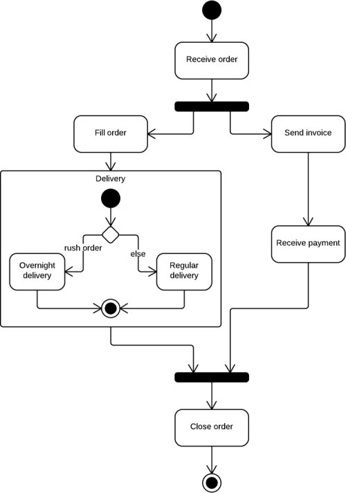
Diagramme de cas d'utilisation
Un cas d'utilisation est une liste d'étapes qui définissent les interactions entre un acteur (un humain qui interagit avec le système ou un système externe) et le système lui-même. Les diagrammes de cas d'utilisation décrivent les spécifications d'un cas d'utilisation et modélisent les unités fonctionnelles d'un système. Ces diagrammes aident les équipes de développeurs à comprendre les besoins de leur système, notamment le rôle des interactions humaines et les différences entre plusieurs cas d'utilisation. Un diagramme d'utilisation peut illustrer tous les cas d'utilisation du système ou seulement un groupe de cas d'utilisation ayant des fonctionnalités similaires.
- Pour commencer un diagramme de cas d'utilisation, ajoutez une forme ovale au centre du dessin.
- Saisissez le nom du cas d'utilisation à l'intérieur de la forme ovale.
- Représentez les acteurs par des bonshommes disposés près du diagramme, puis utilisez des lignes pour modéliser les relations entre acteurs et cas d'utilisation.
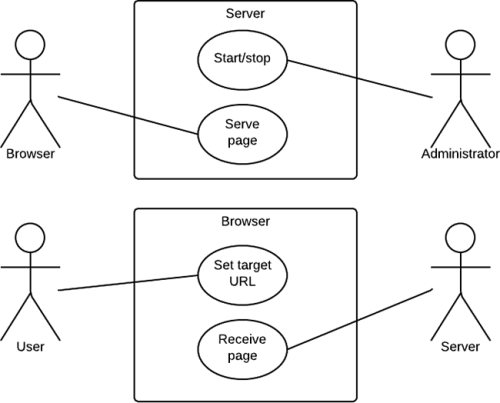
Les diagrammes de séquence, également appelés diagrammes d'événements, illustrent la façon dont des processus interagissent entre eux en montrant les appels entre différents objets dans une séquence. Ces diagrammes ont deux dimensions : verticale et horizontale. Les lignes verticales montrent la séquence de messages et d'appels dans l'ordre chronologique, et les éléments horizontaux montrent les instances d'objets où les messages sont relayés.
- Pour créer un diagramme de séquence , écrivez le nom de l'instance de classe et le nom de la classe dans une case rectangulaire.
- Dessinez des lignes entre les instances de classes pour représenter l'émetteur et le destinataire des messages.
- Utilisez des pointes de flèches pleines pour symboliser les messages synchrones, des pointes de flèches ouvertes pour les messages asynchrones et des lignes en pointillés pour les messages de réponse.
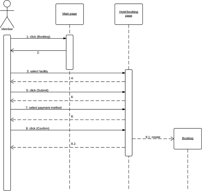
Il est facile de dessiner des diagrammes UML avec Lucidchart
Vous pouvez commencer à créer des diagrammes UML dès maintenant avec Lucidchart. Notre solution est simple, efficace et même amusante.
Simplicité d'utilisation
Bibliothèque complète de formes, intégration complète, option de collaboration, importation/exportation de fichiers visio, ressources additionnelles.
- Qu'est-ce qu'un diagramme de séquence UML ?
- Qu'est-ce qu'un diagramme d'états-transitions ?
- Diagramme d'interaction : définition, avantages et exemples
- Qu'est-ce qu'un diagramme de paquetages UML ?
- Qu'est-ce qu'un diagramme de déploiement UML ?
- Qu'est-ce qu'un diagramme de cas d'utilisation UML ?
- Diagramme d'objet : définition, éléments et application UML
- Qu'est-ce qu'un diagramme d'activité UML ?
- Diagramme de classes UML : définition, avantages, composants et exemples
- Diagramme de composant : définition, avantage et utilisation
- Sochi Tourism
- Sochi Hotels
- Sochi Bed and Breakfast
- Flights to Sochi
- Sochi Restaurants
- Things to Do in Sochi
- Sochi Travel Forum
- Sochi Photos
- All Sochi Hotels
- Sochi Hotel Deals
Lots of lodging has just come available in sochi - Sochi Forum
- Europe
- Russia
- Southern District
- Krasnodar Krai
- Greater Sochi
- Sochi
Lots of lodging has just come available in sochi
- United States Forums
- Europe Forums
- Canada Forums
- Asia Forums
- Central America Forums
- Africa Forums
- Caribbean Forums
- Mexico Forums
- South Pacific Forums
- South America Forums
- Middle East Forums
- Honeymoons and Romance
- Business Travel
- Train Travel
- Traveling With Disabilities
- Tripadvisor Support
- Solo Travel
- Bargain Travel
- Timeshares / Vacation Rentals
- Greater Sochi forums
- Sochi forum

If anyone is still struggling to find Sochi Olympics lodging, a boatload has come available on the web, some (not all) of it reasonably priced.
Russian speakers start here: http://www.snimu-v-sochi.ru . This has by far the best selection and the listings are up to date, most posted in the last 72 hours. Almost every listing has a phone number and you are usually talking direct to the landlord, not to middlemen. I selected a hotel room for 4 with fridge, TV and wifi for $180 per night near the beach in Adler, halfway between the Coastal Cluster and the Adler train station where you catch the express train to the Alpine Cluster.
The second site is in English. The selection is smaller but it has a few good ones, and you can do direct bookings via web: www.iha.com. Select “Map search”, then “Russia”, “Southern Federal District”, “Krasnodar Krai” and then “Sochi”.
Tripadvisor staff removed this post because it did not meet Tripadvisor's forum posting guidelines with prohibiting self-promotional advertising or solicitation.
This topic has been closed to new posts due to inactivity.
- Sochi to Trabzone ferry Oct 01, 2023
- Privat tour guide Nov 22, 2021
- Looking for ski shop that speaks English to buy & fit boots Oct 16, 2020
- Ski holiday in Esto-Sadok Aug 10, 2020
- French expat coming to live in Sochi May 28, 2020
- Crossing the border to Abkhazia,Georgia Dec 30, 2019
- Hospital Oct 08, 2019
- visit to a Sanatorium. Oct 06, 2019
- Where to Stay: Sochi Center or Marriott Hotel? Sep 19, 2019
- Football game on grand prix weekend Sep 08, 2019
- Attractions near the Skypark Aug 10, 2019
- Summer in Sochi Aug 02, 2019
- Ceramic studio in sochi Jul 11, 2019
- private driver Jul 07, 2019
- How to get from Sochi to Tbilisi? 3 replies
- 2014 Olympics- kinda early but,,,where to stay?? 4 replies
- Direct flight Sochi to Dubai 3 replies
- 2014 Olympics 76 replies
- Ferries, cruises 9 replies
- One day in Sochi - what to see and do? 24 replies
- nightlife in sochi 4 replies
- Adler airport to town transportation 2 replies
- October 10, 2011 Black Sea cruise Sochi, Russia 2 replies
- Transportation from Anapa to Sochi 3 replies
- GreenLeaders
- 10 Things To Do In...
10 Things to Do in Sochi If You Love Nature

Host to 2014 Winter Olympics , Sochi is now mostly known for the snowy slopes of Krasnaya Polyana and Rosa Khutor Alpine resort. However, the “Russian Riviera” is much more than a glorified ski-resort. With its picturesque waterfalls and pristine lakes, alpine meadows and spruce-fir forests, snow-capped mountains and dreamy river valleys, Sochi is an ultimate nature lover’s dream.
Aul tkhagapsh.
Founded in the middle of the 19th century, this village only consists of two streets and two lanes. Circled by a picturesque chestnut forest, Aul Tkhagapsh is surrounded by many visually-arresting natural landmarks – a mysterious rock formation called “the canyon of a hundred crying eyes”, beautiful waterfalls with organically formed stone basins and the Tiger cave, which is called so because of the whimsical clay dripstones. Despite its tiny size, the village itself has a lot to offer. You can see the only wooden mosque on the coast, learn about the customs and traditions of the Adyghe people, try on traditional clothes and taste authentic food and local wines.
Aul Tkhagapsh, Krasnodar Krai, Russia

If you love picturesque ancient ruins put the Loo Temple on your must-see list. Drowning in the lush greenery of the Sochi National Park, Loo Temple is the remains of a 10th-century Byzantine temple, that’s been ruined and reconstructed multiple times. The temple was used as a place of worship and a fortification over the years.
Loo Temple, Bolshoy Sochi, Krasnodar Krai,Russia

Aibga Ridge
This spectacular mountain ridge stretches for 23 kilometers and has the Rosa Khutor Alpine Resort nestled at its feet. The ridge comprises of 10 peaks, with the four tallest being the best known: Aigba peak I (2391 m), peak II (2450,5 m), peak III (2462,7 m) and Black Pyramid (2375,3 m). Save a day or two to explore the ridge, full of rapid rivers, alpine meadows and waterfalls.
Aibga Ridge, Krasnodar Krai, Russia

Become a Culture Tripper!
Sign up to our newsletter to save up to $1,200 on our unique trips..
See privacy policy .

Achepsinskie Waterfalls
To admire the spectacular views that Achepsinskie Waterfalls offer, you’ll have to endure a pretty tiring trekking route through the Achishkho Mountain to the Achipse River. But those striking panoramas are totally worth the sweat and while the trekking may be tough going, it has a very decent infrastructure.
Achipse River, Krasnodar Krai, Russia

Khmelevskie Lakes
Located almost 2000 meters above sea level, Khmelevskie Lakes is an alpine lake system, named after the Russian botanist Vikenty Khmelevsky. Spread around emerald-green alpine meadows and surrounded by lush green forests, there are four rather sizable overgrown lakes and a few smaller ones.
Khmelevskie Lake, Krasnodar Krai, Russia

Lake Kardyvach
Arguably the most popular tourist spot near Sochi, Lake Kardyvach is simply breathtaking. Situated 44 kilometers from the Krasnaya Polyana resort at the altitude of 1838 meters, the lake stays frozen for seven to eight months a year and even in summer the water temperature is never hotter than 12℃. The water in the lake changes its color depending on the time of year: in spring it turns green and in autumn it becomes dark blue, and no matter what season, it’s unbelievably clear. Lake Kardyvach, Krasnodar Krai, Russia
Akhshtyrskaya Cave
A unique monument of prehistoric architecture, Akhshtyrskaya Cave is set on the right side of Akhshtyrskaya Gorge, about 120m above the Mzymta River and 185m above sea level. The cave begins with a 20m corridor and then gets divided into two halls, 10m and 8m wide. The cave has been heavily explored by archaeologists, who discovered traces of Neanderthal culture dating back to 40,000 BC.
Akhshtyrskaya Cave, Bolshoy Sochi, Krasnodar Krai,Russia

Shakhe River
Sochi’s second most significant river, Shakhe begins high in the mountains and flows down to the Black Sea . 59 kilometers long, the river has some amazing natural attractions in its valley: Dzhegosh Gorge, 33 waterfalls, stone lake basins, ancient oak trees, rare plant life and so much more.
Shakhe River, Krasnodar Krai,Russia

Agura Waterfalls and Orlinyye Rocks
This is one of the most exciting hiking routes in the area. Taking you through spruce fir forest, to three cascading waterfalls and the sheer cliffs of the Orlinyye Rocks with head-spinning views. Agura Waterfalls, Bolshoy Sochi, Krasnodar Krai,Russia

Words can’t do justice to the virgin beauty of the Khuko Lake and scientists are still puzzling over the absence of any life in it. Set between Adygea and Krasnodar Krai, the lake offers incredible views of the mountains Fisht, Oshten and Pshekha-Su.
Khaki Lake, Krasnodar Krai,Russia

Guides & Tips
A 48 hour guide to astrakhan, russia.

A Guide to Cautionary Russian Proverbs and What They Mean

A Soviet Pilot Went Missing in Afghanistan and Was Found 30 Years Later

Zhenotdel: The Soviet Union's Feminist Movement

The Soviet Union’s Best Heart-Throbs and Pinups

Russian Last Names and Their Meanings

Restaurants
The best halal restaurants in kaliningrad.

Food & Drink
The best halal restaurants in kazan.

The Mystery Behind Russia's Buddhist "Miracle"

Unusual Facts About the Soviet Union

Incredible Photos From the Longest Bike Race in the World

See & Do
Russia's most remote holiday destinations.
Culture Trip Summer Sale
Save up to $1,200 on our unique small-group trips! Limited spots.

- Post ID: 1679788
- Sponsored? No
- View Payload

- Best Landmarks
- Must Visit Attractions
- Best Outdoor Activities
Sochi National Park

"National Treasure"

What's Nearby?

Email Collection
Share/invite, booking details, create new collection, cancellation page, cancellation status, edit collection.

COMMENTS
phenomenon spawned J2EE, SOAP, and Linux.) One reason UML has become a standard modeling language is that it is programming-language independent. (UML modeling tools from IBM Rational are used extensively in J2EE shops as well in .Net shops.) Also, the UML notation set is a language and not a methodology. This is important, because a language,
UML is a way of visualizing a software program using a collection of diagrams. The notation has evolved from the work of Grady Booch, James Rumbaugh, Ivar Jacobson, and the Rational Software Corporation to be used for object-oriented design, but it has since been extended to cover a wider variety of software engineering projects.
UML, short for Unified Modeling Language, is a standardized modeling language consisting of an integrated set of diagrams, developed to help system and software developers for specifying, visualizing, constructing, and documenting the artifacts of software systems, as well as for business modeling and other non-software systems.The UML represents a collection of best engineering practices that ...
Introduction to UML: Unified Modeling Language. This lecture provides an introduction to UML, the Unified Modeling Language. It explains the motivation behind modeling, the concept of systems and views, and the different categories and diagrams used in UML. UML is a standardized graphical language used for specifying, visualizing, constructing ...
Unified Modeling Language (UML) is a standardized visual modeling language used in the field of software engineering to provide a general-purpose, developmental, and intuitive way to visualize the design of a system. UML helps in specifying, visualizing, constructing, and documenting the artifacts of software systems.
Today, UML diagrams are also used to manage processes and projects. In this scenario, UML diagrams outline entire workflows and business processes. UML was created in 1995 by Grady Booch, Ivar Jacobson, and James Rumbaugh. In 1997, the Object Management Group adopted UML, meaning it was rolled out to companies such as Hewlett-Packard, Apple ...
Learn about how to use UML diagrams to visualize the design of databases or systems. You will learn the most widely used Unified Modeling Language diagrams, ...
UML (Unified Modeling Language) is a general purpose visual modeling language that provides different types of diagrammatic techniques and notations to specify, visualize, analyze, construct, and document the artifacts of a software system. UML diagrams are used to understand, design, browse, configure, maintain, and control information about ...
One of the purposes of UML was to provide the development community with a stable and common design language that could be used to develop and build computer applications. UML brought forth a unified standard modeling notation that IT professionals had been wanting for years. Using UML, IT professionals could now read and disseminate system ...
the Unified Modelling Language (UML) Third generation OO method. Booch, Rumbaugh & Jacobson are principal authors. Still evolving (currently version 2.0) Attempt to standardize the proliferation of OO variants. Is purely a notation. No modelling method associated with it! Was intended as a design notation. Has become an industry standard.
A UML diagram is a way to visualize systems and software using Unified Modeling Language (UML). Software engineers create UML diagrams to understand the designs, code architecture, and proposed implementation of complex software systems. UML diagrams are also used to model workflows and business processes.
Object Modeling is a description and analysis tool based upon the object paradigm. Modeling at its core is Analysis, a detailed examination of the elements and structure of something. The object paradigm defines the characteristics and relationships that may exist and provides a network of conceptual primitives that permit a precise description ...
Start a sequence diagram. Start Visio. Or if you have a file open already, select File > New. In the Search box, type UML sequence. Select the UML Sequence diagram. In the dialog box, select the blank template or one of the three starter diagrams. (A description of each one is shown on the right when you select it.)
Create UML diagram in PowerPoint. PowerPoint is one of the popular presentation software which is commonly used by business people and students to create slides for presentations. in addition to that, users can add different content such as diagrams, pie charts, images, and other shapes and symbols.
Activity diagram templates. Activity diagrams in UML are a leading subset of behavioral diagrams. They display the functionalities of various activities and flows in business processes and software systems. With UML-specific symbols, you can map out the start point, end point, and all the merging and interactions in between your process flow.
Le langage UML (Unified Modeling Language, ou langage de modélisation unifié) a été pensé pour être un langage de modélisation visuelle commun, et riche sémantiquement et syntaxiquement. Il est destiné à l'architecture, la conception et la mise en œuvre de systèmes logiciels complexes par leur structure aussi bien que leur comportement.
Sign in to get trip updates and message other travelers.. Sochi ; Hotels ; Things to Do ; Restaurants ; Flights ; Vacation Rentals ; Travel Stories
Krasnodar Krai is located in the southwestern part of the North Caucasus and borders Rostov Oblast in the northeast, Stavropol Krai and Karachay-Cherkessia in the east, and with the Abkhazia region (internationally recognized as part of Georgia) in the south. [14] The Republic of Adygea is completely encircled by the krai territory. The krai's Taman Peninsula is situated between the Sea of ...
Shakhe River. Sochi's second most significant river, Shakhe begins high in the mountains and flows down to the Black Sea. 59 kilometers long, the river has some amazing natural attractions in its valley: Dzhegosh Gorge, 33 waterfalls, stone lake basins, ancient oak trees, rare plant life and so much more.
Sochi National Park is 193,737 hectares (478,735 acres) of natural and cultural wonders. There are mountains, canyons, rivers, waterfalls, gorges, and caves. Among the park's main attractions are Akhun Mountain, the Zmeyka Cascade, the Vorontsovskiye Caves and the Khosta Yew and Boxwood Grove. Cultural attractions include the ruins of a Byzantine temple, a Bronze Age dolmen, and the watchtower ...