Activity Diagram Tutorial | Easy Guide with Examples
Activity diagrams can be used in all stages of software development and for various purposes. And because they are a lot similar to flowcharts, they are generally more popular than other UML diagram types .
In this activity diagram tutorial, we hope to cover everything you need to know about activity diagrams to learn and master them. Scroll down to find;

What is an Activity diagram?
Activity diagram symbols, how to draw an activity diagram, activity diagram examples.
A UML activity diagram helps to visualize a certain use case at a more detailed level. It is a behavioral diagram that illustrates the flow of activities through a system.
They are similar to a flowchart, but with more specific symbols and notations. The purpose of an activity diagram is to model the behavior of a system or process in a clear and structured way, making it easier to understand and analyze.
The main advantage of activity diagrams is that they provide a visual representation of complex systems or processes that can be easily understood by both technical and non-technical stakeholders. They are commonly used in software development to model business processes, use cases, and system workflows. UML activity diagrams can also be used to depict a flow of events in a business process. They can be used to examine business processes in order to identify their flow and requirements.
UML has specified a set of symbols and rules for drawing activity diagrams. Following are the commonly used activity diagram symbols with explanations.
Activity Diagrams with Swimlanes

In activity diagrams, swimlanes – also known as partitions – are used to represent or group actions carried out by different actors in a single thread. Here are a few tips you can follow when using swimlanes.
- Add swimlanes to linear processes. It makes it easy to read.
- Don’t add more than 5 swimlanes.
- Arrange swimlanes in a logical manner.
Activity diagrams can be used to model business requirements, create a high-level view of a system’s functionalities, analyze use cases, and for various other purposes. In each of these cases, here’s how to draw an activity diagram from the beginning.
Step 1: Figure out the action steps from the use case
Here you need to identify the various activities and actions your business process or system is made up of.
Step 2: Identify the actors who are involved
If you already have figured out who the actors are, then it’s easier to discern each action they are responsible for.
Step 3: Find a flow among the activities
Figure out in which order the actions are processed. Mark down the conditions that have to be met in order to carry out certain processes, which actions occur at the same time and whether you need to add any branches in the diagram. And do you have to complete some actions before you can proceed to others?
Step 4: Add swimlanes
You have already figured out who is responsible for each action. Now it’s time to assign them a swimlane and group each action they are responsible for under them.
Click here to start drawing your activity diagram .
Following are activity diagram templates that are instantly editable. Click on the image to open them in the editor so you can make the changes online.
How to choose the right activity diagram template for your project
Choosing the right activity diagram template for a project depends on several factors, including the complexity of the system or process being modeled, the level of detail required, and the specific goals of the project. Here are some factors to consider.
- The first step in choosing the right template is to determine the purpose of the activity diagram. Are you trying to model a business process, a software system, or a workflow?
- The complexity of the system or process being modeled is also an important factor in choosing the right template. If the system or process is simple, a basic template may be sufficient. However, if the system or process is more complex, select a more advanced or detailed template to start with.
- The audience for the activity diagram is also an important consideration. If the diagram is intended for technical stakeholders, a more detailed template may be appropriate. However, if the diagram is intended for non-technical stakeholders, a simpler template may be easier to understand.
Activity Diagram for Login

Activity Diagram for Document Management System

Activity Diagram for Online Shopping System

Activity Diagram for ATM

Activity Diagram for College Management System

Activity Diagram for Library Management System

Activity Diagram for a Railway Reservation System

Activity Diagram for a Project Management System

Share the Activity Diagram Tutorial
We’ve covered everything you need to know about activity diagrams in this activity diagram tutorial. Have you got more to add?
If you haven’t seen it yet, we recently published an Easy Guide to UML Class Diagrams . What other UML diagram types do you want us to cover? Do let us know in the comment section below. And don’t forget to share the activity diagram tutorial with your friends.
Join over thousands of organizations that use Creately to brainstorm, plan, analyze, and execute their projects successfully.
FAQs about Activity Diagrams
Activity diagrams are useful in a number of scenarios.
- An activity diagram provides a clear and easy-to-understand pictorial representation of how the software system will function.
- Provides a high-level overview of a system’s functionality which any non-technical person can quickly understand.
- Activity diagrams help effectively document and visualize the exact process and steps involved in the developmental process.
- They have different uses for all phases of a software development project. During the planning stage activity diagrams can be used to visualize the workflows within a system, while during the requirements gathering stage they can be used for representing the different use cases of a system.
- Activity diagrams can also be used to understand the requirements of business processes more effectively.
Activity diagrams are used in software modeling as well as business modeling. Most commonly activity diagrams are used to;
- Capture the dynamic behavior of a system, application, or process.
- Create a high-level overview of the workflow of any application or system.
- Visualize the flow of events that a UML use case describes.
- Model various software elements such as method, function, and operation.
- Highlights the multiple conditions and actors within a workflow through the use of swimlanes.
Activity diagrams represent the flow of activities within a system and depict the workflow/ interaction between these various system activities. Flowcharts, on the other hand, represent the sequence of steps in an event, process, or system. While they look similar, activity diagrams are more advanced as they possess unique capabilities that flowcharts lack. Activity diagrams contain unique elements such as branching, parallel flow, control nodes, expansion nodes, swimlanes, and object nodes.
In order to draw a correct activity diagram, one must first understand the entire system and the various conditions, associations, and constraints applied to its activities which should be noted before creating the activity diagram.
More Related Articles

Amanda Athuraliya is the communication specialist/content writer at Creately, online diagramming and collaboration tool. She is an avid reader, a budding writer and a passionate researcher who loves to write about all kinds of topics.
You are using an outdated browser. Please upgrade your browser .
T4Tutorials.com
Activity diagram | scenario and case study base project examples.
Activity diagrams are behavioral diagrams.

Activity VS Task
An activity is work that is done with no specific purpose in mind or in some cases, activity can have a mini purpose.
The task is a big term as compared to activity and task is specifically an activity that is done with only having a particular purpose in mind.
What is Activity?
A project is divided into many interdependent activities to complete a task.
The sequence or the order of the activities is very important.

Activity Diagram Case Study 1
Suppose we want to develop a web-based social network with the following functionalities;
The user should signup for the system.
The user should log into the system and can send friend requests or block the user.
We need to convert this system into separate components;
Activity 1: Sign up
Activity 2: log in
Activity 3: Send Friend request
Activity 4: block a user
Explicit requirements VS implicit requirements
Explicit requirements:.
- Clearly described by the customers
implicit requirements :
- Not Understood
- Not Clearly described r by the customers
Activity Diagram for module 1 of case study 1

Activity Diagram for module 2 of case study 1

Activity Diagram for module 1 of case study 2
The user can search books, viewbooks Without any fee but can download the Book only and only if he pays money. Provide the facility of managing the cart To the user, so that he can update his cart.

How many activity diagrams for 1 Project?
In most of the cases;
- 1 activity diagram for each separate module of your project.
- The activity of one module can also be drawn in another module if required.
- Don’t mix all activities of all modules of your big project in only one diagram.
- 1 diagram represents the flow of one selected activity from starting to end. Only helping activities can be drawn with the selected activity.
Purpose of Activity Diagram
- Draw the activity flow for a system
- Describe the sequence from one activity to another
- High-level understanding of the system’s functionalities
- Modeling business requirements
- Investigating business requirements as and when required
UML Diagrams MCQs Questions Answers
Related Posts:
- Activity Diagram of Karate Club Management System Project
- Activity Diagram of Daily Expense Tracker Android App Project
- Activity Diagram of Housing Society Management System
- Activity diagram MCQs
- Comparison of Use Case Diagram VS Class diagram
- Incremental Model, advantages, examples, Case study
Home » UML » Understanding Activity Diagrams in UML: A Comprehensive Guide
Understanding Activity Diagrams in UML: A Comprehensive Guide
- Posted on September 13, 2023
- / Under UML
Introduction
Unified Modeling Language (UML) is a powerful tool for visualizing and documenting software systems. Among the various UML diagrams, the Activity Diagram is a versatile and essential tool for modeling and describing the dynamic aspects of a system’s behavior. Whether you’re a software developer, system analyst, or project manager, understanding Activity Diagrams can significantly improve your ability to design and communicate complex processes within a system. In this article, we’ll explore what Activity Diagrams are, their components, and how to create and interpret them.
What is an Activity Diagram?
An Activity Diagram is one of the behavioral diagrams in UML, used to model the dynamic aspects of a system. It focuses on illustrating the workflow or sequence of activities, actions, and decisions within a system or a process. These diagrams are particularly useful for modeling business processes, software algorithms, and workflow scenarios, making them a valuable tool for software design, system analysis, and process optimization.
Benefits of Activity Diagrams
Activity Diagrams offer several benefits in the software development and system modeling process:
- Clarity: They provide a clear and intuitive visual representation of complex processes, making it easier for stakeholders to understand and discuss.
- Communication: Activity Diagrams serve as effective communication tools between different stakeholders, including developers, analysts, and project managers.
- Process Improvement: They help in identifying bottlenecks, inefficiencies, and areas for process improvement.
- Documentation: Activity Diagrams can be used as part of system documentation to explain how a process works.
- Validation: They allow for the validation of business and system processes before implementation.
Components of an Activity Diagram
To effectively use Activity Diagrams, it’s essential to understand their key components:
- Activity: An activity is a fundamental unit of work within an Activity Diagram. It represents a task, action, or operation that is performed as part of a process. Activities are usually depicted as rectangles with rounded corners.
- Initial Node: The initial node signifies the starting point of the activity diagram. It is typically represented as a small circle with an arrow pointing outward, connecting to the first activity.
- Final Node: The final node represents the endpoint of the activity diagram. It is depicted as a circle with a small dot inside or as a larger circle. It indicates the termination of the process.
- Control Flow: Control flow arrows, often referred to as control edges, connect activities and depict the sequence in which they are executed. These arrows show the order of execution, which helps in understanding the flow of the process.
- Decision Node: Decision nodes are represented as diamonds and are used to represent points in the process where a decision or branching occurs. Depending on the condition or criteria, the flow can follow different paths.
- Merge Node: Merge nodes, also represented as diamonds, are used to merge multiple flows back into a single flow after a decision or branching point. They ensure that multiple paths converge.
- Fork Node: Fork nodes represent the point at which one flow splits into multiple concurrent flows, indicating that multiple activities can happen simultaneously.
- Join Node: Join nodes represent the point at which multiple concurrent flows merge back into a single flow, indicating that parallel activities have completed.
- Swimlanes: Swimlanes are used to partition the activities in an Activity Diagram, typically to indicate which entity or actor is responsible for each task. They are represented as vertical or horizontal containers.
Creating an Activity Diagram
To create an Activity Diagram, follow these steps:
- Identify the Process: Clearly define the process you want to model. This may involve understanding the actors involved, the activities performed, and any decision points within the process.
- Identify Activities: Break down the process into individual activities or tasks that need to be represented in the diagram.
- Add Initial and Final Nodes: Place the initial node at the start of the diagram and the final node at the end.
- Connect Activities: Use control flow arrows to connect activities in the order they occur.
- Add Decision Nodes: If there are decision points in your process, add decision nodes (diamonds) and connect them with control flow arrows.
- Add Merge Nodes: For each decision node, add a corresponding merge node to show where the diverging paths rejoin.
- Use Fork and Join Nodes: If there are parallel activities in your process, add fork and join nodes to indicate the splitting and merging of flows.
- Partition with Swimlanes: If necessary, use swimlanes to partition activities by the responsible entity or actor.
- Label Activities: Add labels to activities and decision nodes to provide clear descriptions of what each represents.
- Specify Conditions: If applicable, include conditions or guards on control flow arrows to denote decision outcomes.
Interpreting an Activity Diagram
Interpreting an Activity Diagram involves understanding the sequence of activities, decision points, and the flow of control through the diagram. Here are some key points to consider:
- Follow the control flow arrows from the initial node to the final node to trace the sequence of activities.
- Pay attention to decision nodes; depending on the conditions specified, the flow can take different paths.
- Look for fork and join nodes to identify parallel activities and understand where they diverge and converge.
- Swimlanes help in identifying which entity or actor is responsible for each task.
- The labels on activities and decision nodes should provide clear descriptions of what each represents.
Activity Diagram Example

In cases where only one person is involved in the process, the concurrent activities can be executed in any order, presuming they cannot be performed simultaneously (though the model permits such simultaneous execution, it might be impractical in reality). For instance, theater box office personnel could either assign seats, then award bonuses, and finally debit the account, or they could start by awarding bonuses, then assigning seats, and lastly, debiting the account. However, it’s essential to note that debiting the account cannot occur until after the seats have been assigned.
Within this process, there is a conditional thread emerging from the fork point. This thread evaluates whether the subscriber is a member, serving as a guard condition. It only initiates if the guard condition is met. If the subscriber is not a member, only one thread is activated, responsible for seat assignment and account debiting, without waiting for synchronization at the join point.
Swimland Activity Diagram Example

Furthermore, the diagram incorporates object flow symbols, which depict the different states of an “order” object as it traverses a network of activities. For instance, the “Order[placed]” symbol indicates that at that point in the computation, an order has transitioned to the “placed” state within the “Request Service” activity but has not yet been consumed by the “Take Order” activity. After the “Take Order” activity concludes, the order moves to the “entered” state, as evidenced by the object flow symbol following the “Take Order” activity. All the object flows in this instance represent the same object at different stages of its life. As they represent the same object, they cannot coexist simultaneously, and a sequential control path connects them, as evident in the diagram.
Object flow is employed to represent objects that serve as inputs to or outputs from an action. These symbols indicate the object’s state at the specific point in the computation when it is either suitable as an input or just produced as an output (typically, an object fulfills both roles). A dashed arrow links an outgoing transition of an activity state to an object flow, which constitutes one of its outputs. Conversely, another dashed arrow connects the object flow to an incoming transition into an activity state, indicating that the object serves as one of its inputs. Frequently, the same object can be both the output of one activity and the input for one or more subsequent activities.
Activity Diagrams in UML are powerful tools for modeling and visualizing dynamic aspects of a system or process. By understanding the components and principles of Activity Diagrams, you can effectively model complex workflows, improve communication among stakeholders, and optimize processes. Whether you’re involved in software development, business process analysis, or system design, Activity Diagrams can be a valuable addition to your toolkit, helping you create more efficient and well-documented systems.
Leave a Comment Cancel reply
Your email address will not be published. Required fields are marked *
Save my name, email, and website in this browser for the next time I comment.
- Visual Paradigm Online
- Request Help
- Customer Service
- Community Circle
- Demo Videos
- Visual Paradigm
- YouTube Channel
- Academic Partnership
- System Design Tutorial
What is System Design
- System Design Life Cycle
- High Level Design HLD
- Low Level Design LLD
- Design Patterns
- UML Diagrams
- System Design Interview Guide
- Crack System Design Round
- System Design Bootcamp
- System Design Interview Questions
- Microservices
- Scalability
- System Design Interview Bootcamp - A Complete Guide
- What is Systems Design - Learn System Design
- System Design Life Cycle | SDLC (Design)
- What are the components of System Design?
- Goals and Objectives of System Design
- Why is it important to learn System Design?
- Important Key Concepts and Terminologies – Learn System Design
- Advantages of System Design
System Design Fundamentals
- Analysis of Monolithic and Distributed Systems - Learn System Design
- Structured Analysis and Structured Design (SA/SD)
- System Design Strategy - Software Engineering
- Database Sharding | System Design
- Horizontal and Vertical Scaling | System Design
- Load Balancer - System Design Interview Question
- Routing requests through Load Balancer
- Caching - System Design Concept
- Object-Oriented Analysis and Design(OOAD)
- 6 Steps To Approach Object-Oriented Design Questions in Interview
- Difference between Structured and Object-Oriented Analysis
- Communication Protocols In System Design
- Web Server, Proxies and their role in Designing Systems
Scalability in System Design
- What is Scalability and How to achieve it?
- Which Scalability approach is right for our Application? | System Design
- Primary Bottlenecks that Hurt the Scalability of an Application | System Design
Databases in Designing Systems
- Complete Reference to Databases in Designing Systems - Learn System Design
- SQL vs NoSQL: Which Database to Choose in System Design?
- File and Database Storage Systems in System Design
- Block, Object, and File Storage in Cloud with Difference
- Normalization Process in DBMS
- Denormalization in Databases
High Level Design(HLD)
- What is High Level Design – Learn System Design
- Availability in System Design
- Consistency Model in Distributed System
- Reliability in System Design
- The CAP Theorem in DBMS
- Difference between Process and Thread
- Difference between Concurrency and Parallelism
Activity Diagrams | Unified Modeling Language (UML)
Low level design(lld).
- What is Low Level Design or LLD - Learn System Design
- Difference between Authentication and Authorization
- What is Data Encryption?
- Code Optimization in Compiler Design
- Unit Testing - Software Testing
- Integration Testing - Software Engineering
- CI/CD: Continuous Integration and Continuous Delivery
- Introduction to Modularity and Interfaces In System Design
- Unified Modeling Language (UML) Diagrams
- Data Partitioning Techniques in System Design
Testing and Quality Assurance
- Types of Software Testing
- Software Quality Assurance - Software Engineering
- Essential Security Measures in System Design
Interview Guide for System Design
- How to Crack System Design Interview Round
- Grokking Modern System Design Interview Guide
- System Design Interview Questions and Answers
- Most Commonly Asked System Design Interview Problems/Questions
- 5 Common System Design Concepts for Interview Preparation
- 5 Tips to Crack Low-Level System Design Interviews
System Design Interview Questions & Answers
- Design Dropbox - A System Design Interview Question
- Designing Twitter - A System Design Interview Question
- System Design Netflix | A Complete Architecture
- System Design of Uber App | Uber System Architecture
- Design BookMyShow - A System Design Interview Question
- Designing Facebook Messenger | System Design Interview
- Software Design Patterns Tutorial
- Complete Roadmap to Learn System Design for Beginners
Activity Diagrams are used to illustrate the flow of control in a system and refer to the steps involved in the execution of a use case. It is a type of behavioral diagram and we can depict both sequential processing and concurrent processing of activities using an activity diagram ie an activity diagram focuses on the condition of flow and the sequence in which it happens.
-Activity-Diagrams-(2).jpg "activity diagram case study")
Important Topics for the Activity Diagrams
- What is an Activity Diagram?
- Activity Diagram Notations
- How to Draw an Activity Diagram in UML?
- What are Activity Diagrams used for?
- What are the Differences between an Activity diagram and a Flowchart?
1. What is an Activity Diagram?
Activity Diagrams are used to illustrate the flow of control in a system and refer to the steps involved in the execution of a use case. We can depict both sequential processing and concurrent processing of activities using an activity diagram ie an activity diagram focuses on the condition of flow and the sequence in which it happens.
- We describe what causes a particular event using an activity diagram.
- An activity diagram portrays the control flow from a start point to a finish point showing the various decision paths that exist while the activity is being executed.
- They are used in business and process modeling where their primary use is to depict the dynamic aspects of a system.
2. Activity Diagram Notations

In activity diagrams, the notations are like visual symbols that help represent different elements and actions in a simple way.
2.1. Initial State
The starting state before an activity takes place is depicted using the initial state.

A process can have only one initial state unless we are depicting nested activities. We use a black filled circle to depict the initial state of a system. For objects, this is the state when they are instantiated. The Initial State from the UML Activity Diagram marks the entry point and the initial Activity State.
For example:
Here the initial state of the system before the application is opened.
.jpg "activity diagram case study")
2.2. Action or Activity State
An activity represents execution of an action on objects or by objects. We represent an activity using a rectangle with rounded corners. Basically any action or event that takes place is represented using an activity.

Consider the previous example of opening an application, opening the application is an activity state in the activity diagram.

2.3. Action Flow or Control flows
Action flows or Control flows are also referred to as paths and edges. They are used to show the transition from one activity state to another activity state.

An activity state can have multiple incoming and outgoing action flows. We use a line with an arrow head to depict a Control Flow. If there is a constraint to be adhered to while making the transition it is mentioned on the arrow.
For example :
Here both the states transit into one final state using action flow symbols i.e. arrows.

2.4. Decision node and Branching
When we need to make a decision before deciding the flow of control, we use the decision node. The outgoing arrows from the decision node can be labelled with conditions or guard expressions. It always includes two or more output arrows.

We apply the conditions on input number to display the result : If number is odd then display the number. If number if even then display the error.
A Guard refers to a statement written next to a decision node on an arrow sometimes within square brackets.

The statement must be true for the control to shift along a particular direction. Guards help us know the constraints and conditions which determine the flow of a process.
Fork nodes are used to support concurrent activities. When we use a fork node when both the activities get executed concurrently i.e. no decision is made before splitting the activity into two parts. Both parts need to be executed in case of a fork statement. We use a rounded solid rectangular bar to represent a Fork notation with incoming arrow from the parent activity state and outgoing arrows towards the newly created activities.

In the example below, the activity of making coffee can be split into two concurrent activities and hence we use the fork notation.
Join nodes are used to support concurrent activities converging into one. For join notations we have two or more incoming edges and one outgoing edge.

When both activities i.e. steaming the milk and adding coffee get completed, we converge them into one final activity.

2.8. Merge or Merge Event
Scenarios arise when activities which are not being executed concurrently have to be merged. We use the merge notation for such scenarios. We can merge two or more activities into one if the control proceeds onto the next activity irrespective of the path chosen.

In the diagram below: we can’t have both sides executing concurrently, but they finally merge into one. A number can’t be both odd and even at the same time.
.jpg "activity diagram case study")
2.9. Swimlanes
We use Swimlanes for grouping related activities in one column. Swimlanes group related activities into one column or one row. Swimlanes can be vertical and horizontal. Swimlanes are used to add modularity to the activity diagram. It is not mandatory to use swimlanes. They usually give more clarity to the activity diagram. It’s similar to creating a function in a program. It’s not mandatory to do so, but, it is a recommended practice.

We use a rectangular column to represent a swimlane as shown in the figure above.
Here different set of activities are executed based on if the number is odd or even. These activities are grouped into a swimlane.

2.10. Time Event
This refers to an event that stops the flow for a time; an hourglass depicts it. We can have a scenario where an event takes some time to completed.

Let us assume that the processing of an image takes a lot of time. Then it can be represented as shown below.

2.11. Final State or End State
The state which the system reaches when a particular process or activity ends is known as a Final State or End State. We use a filled circle within a circle notation to represent the final state in a state machine diagram. A system or a process can have multiple final states.

3. How to Draw an Activity Diagram in UML?

Below are the steps of how to draw the Activity Diagram in UML:
Step 1. Identify the Initial State and Final States:
- This is like setting the starting point and ending point of a journey.
- Identify where your process begins (initial state) and where it concludes (final states).
- For example, if you are modelling a process for making a cup of tea, the initial state could be “No tea prepared,” and the final state could be “Tea ready.”
Step 2. Identify the Intermediate Activities Needed:
- Think of the steps or actions required to go from the starting point to the ending point.
- These are the activities or tasks that need to be performed.
- Continuing with the tea-making , intermediate activities could include “Boil water,” “Pour tea into a cup”.
Step 3. Identify the Conditions or Constraints:
- Consider the conditions or circumstances that might influence the flow of your process.
- These are the factors that determine when you move from one activity to another.
- Using the tea-making scenario, a condition could be “Water is boiled,” which triggers the transition to the next activity.
Step 4. Draw the Diagram with Appropriate Notations:
- Now, represent the identified states, activities, and conditions visually using the appropriate symbols and notations in an activity diagram. This diagram serves as a visual map of your process, showing the flow from one state to another.
4. What are Activity Diagrams used for?
Activity diagrams are used in software development and system design to model and visualize the dynamic aspects of a system. Here are some common uses of activity diagrams:
- Dynamic modelling of the system or a process.
- Illustrate the various steps involved in a UML use case.
- Model software elements like methods,operations and functions.
- We can use Activity diagrams to depict concurrent activities easily.
- Show the constraints, conditions and logic behind algorithms.
- During the requirements analysis phase, activity diagrams assist in capturing and documenting the dynamic aspects of user interactions.
5. What are the Differences between an Activity diagram and a Flowchart?
An activity diagram is very similar to a flowchart. So let us understand if activity diagrams or flowcharts are any different.
What is a Flow Chart?
An algorithm is like a set of clear instructions to solve a problem, and a flowchart is a picture that shows those instructions.
- When we’re writing computer programs, a flowchart helps us map out the steps of the algorithm to solve the problem.
- Non programmers use Flow charts to model workflows.
- We can call a flowchart a primitive version of an activity diagram.
- Business processes where decision making is involved is expressed using a flow chart.
A manufacturer uses a flow chart to explain and illustrate how a particular product is manufactured.
What are the differences?
Do we need to use both the diagrams and the textual documentation?
Let’s understand this with the help of an example:
- Different individuals have different preferences in which they understand something.
- To understand a concept, some people might prefer a written tutorial with images while others would prefer a video lecture.
- So we generally use both the diagram and the textual documentation to make our system description as clear as possible.
6. Conclusion
In conclusion, Activity Diagrams serve as invaluable tools in system design and analysis, offering a visual representation of dynamic processes within organizations. They are widely utilized to model business processes, illustrate user interactions, and guide software system design. By providing a clear and concise overview of activities, decision points, and interactions, activity diagrams enhance communication among project stakeholders and contribute to effective documentation.
Please Login to comment...
Similar reads.
- Design Pattern
- System Design
Improve your Coding Skills with Practice
What kind of Experience do you want to share?
Diagramming Build diagrams of all kinds from flowcharts to floor plans with intuitive tools and templates.
Whiteboarding collaborate with your team on a seamless workspace no matter where they are., data generate diagrams from data and add data to shapes to enhance your existing visuals., enterprise friendly easy to administer and license your entire organization., security see how we keep your data safe., apps & integrations connect to all the tools you use from microsoft, google workspace, atlassian, and more..
- What's New Read about new features and updates.
Product Management Roadmap features, brainstorm, and report on development, so your team can ship features that users love.
Software engineering design and maintain complex systems collaboratively., information technology visualize system architecture, document processes, and communicate internal policies., sales close bigger deals with reproducible processes that lead to successful onboarding and training..
- Getting Started Learn how to make any type of visual with SmartDraw. Familiarize yourself with the UI, choosing templates, managing documents, and more.
- Templates get inspired by browsing examples and templates available in SmartDraw.
Diagrams Learn about all the types of diagrams you can create with SmartDraw.
Whiteboard learn how to combine free-form brainstorming with diagram blueprints all while collaborating with your team., data visualizers learn how to generate visuals like org charts and class diagrams from data., development platform browse built-in data visualizers and see how you can build your own custom visualization., open api the smartdraw api allows you to skip the drawing process and generate diagrams from data automatically., shape data add data to shapes, import data, export manifests, and create data rules to change dashboards that update..
- Explore SmartDraw Check out useful features that will make your life easier.
- Blog Read articles about best practices, find tips on collaborating, learn to give better presentations and more.
Support Search through SmartDraw's knowledge base, view frequently asked questions, or contact our support team.
Site license site licenses start as low as $2,995 for your entire organization..
- Team License The SmartDraw team License puts you in control with powerful administrative features.
Apps & Integrations Connect to all the tools you use.
- Contact Sales
What's New?

Solutions By Team
Save money, reduce hassle, and get more.
Unleash your team's productivity by combining enterprise-class diagramming, whiteboarding, and data while saving 10x over Visio and Lucidchart!

Getting Started Learn to make visuals, familiarize yourself with the UI, choosing templates, managing documents, and more.
Templates get inspired by browsing examples and templates available in smartdraw., developer resources, additional resources.

Team License The SmartDraw Team License puts you in control with powerful administrative features.
Solutions for your team.

Activity Diagram
Quickly create activity diagrams and other uml style diagrams with smartdraw, what is an activity diagram, activity diagram symbols, how to make an activity diagram, how to make uml diagrams, uml diagram tips, other uml diagrams, with smartdraw, you can create many different types of diagrams, charts, and visuals.
An activity diagram visually presents a series of actions or flow of control in a system similar to a flowchart or a data flow diagram . Activity diagrams are often used in business process modeling. They can also describe the steps in a use case diagram . Activities modeled can be sequential and concurrent. In both cases an activity diagram will have a beginning (an initial state) and an end (a final state).
In between there are ways to depict activities, flows, decisions, guards, merge and time events and more. Learn about activity diagram symbols below:

Activity Diagram Tutorial
You can make an activity diagram by connecting and joining various activity states. The starting point is usually marked with a dark, filled-in circle with an arrow pointing to the next state usually a rectangle with rounded corners. All action flows are represented with arrows indicating the transitions from state to state.
SmartDraw makes drawing activity diagrams easy with built-in activity diagram templates that already have all the basic symbols docked and the tools to connect everything at your fingertips.
Basic Activity Diagram Notations and Symbols
Initial state or start point.
A small filled circle followed by an arrow represents the initial action state or the start point for any activity diagram. For activity diagram using swimlanes, make sure the start point is placed in the top left corner of the first column.

Activity or Action State
An action state represents the non-interruptible action of objects. You can draw an action state in SmartDraw using a rectangle with rounded corners.

Action Flow
Action flows, also called edges and paths, illustrate the transitions from one action state to another. They are usually drawn with an arrowed line.

Object Flow
Object flow refers to the creation and modification of objects by activities. An object flow arrow from an action to an object means that the action creates or influences the object. An object flow arrow from an object to an action indicates that the action state uses the object.

Decisions and Branching
A diamond represents a decision with alternate paths. When an activity requires a decision prior to moving on to the next activity, add a diamond between the two activities. The outgoing alternates should be labeled with a condition or guard expression. You can also label one of the paths "else."

In UML, guards are a statement written next to a decision diamond that must be true before moving next to the next activity. These are not essential, but are useful when a specific answer, such as "Yes, three labels are printed," is needed before moving forward.

Synchronization
A fork node is used to split a single incoming flow into multiple concurrent flows. It is represented as a straight, slightly thicker line in an activity diagram.
A join node joins multiple concurrent flows back into a single outgoing flow.
A fork and join mode used together are often referred to as synchronization.

This refers to an event that stops the flow for a time; an hourglass depicts it.

Merge Event
A merge event brings together multiple flows that are not concurrent.

Sent and Received Signals
Signals represent how activities can be modified from outside the system. They usually appear in pairs of sent and received signals, because the state can't change until a response is received, much like synchronous messages in a sequence diagram . For example, an authorization of payment is needed before an order can be completed.

Interrupting Edge
An event, such as a cancellation, that interrupts the flow denoted with a lightning bolt.

Swimlanes group related activities into one column.

Final State or End Point
An arrow pointing to a filled circle nested inside another circle represents the final action state.

More Activity Diagram Information
- UML diagram tool
- Software design diagram templates
- Data flow diagram software
Try SmartDraw's Activity Diagram Software Free
Discover why SmartDraw is the best activity diagram software today.
UML activity diagram example
This UML activity diagram template can help you:
Describe what must happen in the system being modeled.
Illustrate a business process or workflow between users and the system.
Improve any process by clarifying complicated use cases.
Open this template to view a detailed example of a UML activity diagram that you can customize to your use case.

Related templates

System landscape

Example of perform test activities

Facility quality control example

Automotive Cloud Data Model
UML Activity Diagram Examples
Here we provide several examples of UML activity diagrams :
Purpose : An example of activity diagram for online shopping.
Summary : Online customer can browse or search items, view specific item, add it to shopping cart, view and update shopping cart, do checkout. User can view shopping cart at any time.

Purpose : An example of UML activity diagram describing behavior of the Purchase Ticket use case for a Ticket vending machine.
Summary : Activity is started by Commuter actor who needs to buy a ticket. Ticket vending machine will request trip information from Commuter. Based on the info machine will calculate payment due and request payment options. After payment is complete, ticket is dispensed to the Commuter.

Purpose : An example of business flow UML activity diagram to process purchase order.
Summary : Requested order is input parameter of the activity. After order is accepted and all required information is filled in, payment is accepted and order is shipped.

Purpose : An example of UML activity diagram describing a Document Management Process. Some kind of formal and properly communicated document management process is usually required in any major corporation especially under a regulatory compliance.
Summary : Document is created, reviewed, updated, approved, and at some point archived. This activity diagram example shows responsibilities of different roles and a flow of document changes. Partitions represent different roles participating in the activity - Author, Reviewer, Approver, and Owner.

Purpose : Electronic prescriptions UML activity diagram example is based on documentation for the Electronic Prescription Service (EPS) R2 developed by the NHS Connecting for Health (NHS CFH) in England.
Summary : Prescribers could send prescriptions electronically to a pharmacy of the patient's choice where patient can pick it up. Dispenser retrieves electronic prescriptions from the EPS.

Purpose : An example of UML activity diagram to resolve an issue in software design.
Summary : After issue or error ticket is created by some authority and the issue was reproduced, issue is identified, resolution is determined, issue is fixed and verified, and ticket is closed, if issue was resolved.

Purpose : An example of activity diagram describing manual activation of trial (provisional) product which was protected by Sentinel HASP SL software key of the Sentinel HASP - software protection and licensing security solution.
Summary : Customer has some trial product installed, for example, some game or tool, which has specific trial period and could have some limited features or options. After using the product for some time customer decides to activate product by requesting a permanent, full product license. Order Manager creates a new activation key for the product.

Purpose : An example of UML activity diagram which describes Single Sign-On (SSO) to Google Apps for customers using some hosted Google application, such as Gmail.
Summary : When a user attempts to use some hosted Google application, such as Gmail, Google generates a SAML authentication request and sends redirect request back to the user's browser. Redirect points to the specific identity provider. SAML authentication request contains the encoded URL of the Google application that the user is trying to reach.
 for Google Apps UML activity diagram example.")
Activity Diagram in UML: Symbol, Components & Example
What is an Activity Diagram in UML?
ACTIVITY DIAGRAM is basically a flowchart to represent the flow from one activity to another activity. The activity can be described as an operation of the system. The basic purpose of activity diagrams is to capture the dynamic behavior of the system.. It is also called object-oriented flowchart.
This UML diagram focuses on the execution and flow of the behavior of a system instead of implementation. Activity diagrams consist of activities that are made up of actions that apply to behavioral modeling technology.
Components of Activity Diagram
It is a behavior that is divided into one or more actions. Activities are a network of nodes connected by edges. There can be action nodes, control nodes, or object nodes. Action nodes represent some action. Control nodes represent the control flow of an activity. Object nodes are used to describe objects used inside an activity. Edges are used to show a path or a flow of execution. Activities start at an initial node and terminate at a final node.
Activity partition/swimlane
An activity partition or a swimlane is a high-level grouping of a set of related actions. A single partition can refer to many things, such as classes, use cases, components, or interfaces.
If a partition cannot be shown clearly, then the name of a partition is written on top of the name of an activity.
Fork and Join nodes
Using a fork and join nodes, concurrent flows within an activity can be generated. A fork node has one incoming edge and numerous outgoing edges. It is similar to one too many decision parameters. When data arrives at an incoming edge, it is duplicated and split across numerous outgoing edges simultaneously. A single incoming flow is divided into multiple parallel flows.
A join node is opposite of a fork node as It has many incoming edges and a single outgoing edge. It performs logical AND operation on all the incoming edges. This helps you to synchronize the input flow across a single output edge.
An activity diagram that has a lot of flows gets very complicated and messy.
Pins are used to clearing up the things. It provides a way to manage the execution flow of activity by sorting all the flows and cleaning up messy thins. It is an object node that represents one input to or an output from an action.
Both input and output pins have precisely one edge.
Why use Activity Diagrams?
Activity diagram in UML allows you to create an event as an activity which contains a collection of nodes joined by edges. An activity can be attached to any modeling element to model its behavior. Activity diagrams are used to model,
- Collaborations
Activity diagrams are used to model processes and workflows. The essence of a useful activity diagram is focused on communicating a specific aspect of a system’s dynamic behavior. Activity diagrams capture the dynamic elements of a system.
Activity diagram is similar to a flowchart that visualizes flow from one activity to another activity. Activity diagram is identical to the flowchart, but it is not a flowchart. The flow of activity can be controlled using various control elements in the UML flow diagram. In simple words, an activity diagram is used to activity diagrams that describe the flow of execution between multiple activities.
Activity Diagram Notations
Activity diagrams symbols can be generated by using the following notations:
- Initial states: The starting stage before an activity takes place is depicted as the initial state
- Final states: The state which the system reaches when a specific process ends is known as a Final State
- State or an activity box:
- Decision box: It is a diamond shape box which represents a decision with alternate paths. It represents the flow of control.

How to draw an activity diagram?
Activity diagram is a flowchart of activities. It represents the workflow between various system activities. Activity diagrams are similar to the flowcharts, but they are not flowcharts. Activity diagram is an advancement of a flowchart that contains some unique capabilities.
Activity diagrams include swimlanes, branching, parallel flow, control nodes, expansion nodes, and object nodes. Activity diagram also supports exception handling.
To draw an activity diagram, one must understand and explore the entire system. All the elements and entities that are going to be used inside the diagram must be known by the user. The central concept which is nothing but an activity must be clear to the user. After analyzing all activities, these activities should be explored to find various constraints that are applied to activities. If there is such a constraint, then it should be noted before developing an activity diagram.
All the activities, conditions, and associations must be known. Once all the necessary things are gathered, then an abstract or a prototype is generated, which is later converted into the actual diagram.
Following rules must be followed while developing an activity diagram,
- All activities in the system should be named.
- Activity names should be meaningful.
- Constraints must be identified.
- Activity associations must be known.
Example of Activity Diagram
Let us consider mail processing activity as a sample for Activity Diagram. Following diagram represents activity for processing e-mails.

In the above activity diagram, three activities are specified. When the mail checking process begins user checks if mail is important or junk. Two guard conditions [is essential] and [is junk] decides the flow of execution of a process. After performing the activity, finally, the process is terminated at termination node.
When Use Activity Diagram
Activity diagram is used to model business processes and workflows. These diagrams are used in software modeling as well as business modeling.
Most commonly activity diagrams are used to,
- Model the workflow in a graphical way, which is easily understandable.
- Model the execution flow between various entities of a system.
- Model the detailed information about any function or an algorithm which is used inside the system.
- Model business processes and their workflows.
- Capture the dynamic behavior of a system.
- Generate high-level flowcharts to represent the workflow of any application.
- Model high-level view of an object-oriented or a distributed system.
- Activity diagram is also called as object-oriented flowcharts .
- Activity diagrams consist of activities that are made up of smaller actions.
- Activity is a behavior that is divided into one or more actions.
- It uses action nodes, control nodes and object nodes.
- An activity partition or a swimlane is a high-level grouping of a set of related actions.
- Fork and join nodes are used to generate concurrent flows within an activity.
- Activity diagram is used to model business processes and workflows.
- UML Use Case Diagram: Tutorial with EXAMPLE
- UML Relationships Types: Association, Dependency, Generalization
- UML Association Vs. Aggregation Vs. Composition [EXAMPLE]
- Interaction, Collaboration & Sequence Diagrams with Examples
- UML Tutorial PDF for Beginners
- 13 Best FREE Microsoft Visio Alternatives & Competitors (2024)
- UML Diagram Cheat Sheet and Reference Guide
- Difference Between Aggregation and Composition in UML
- Demo Videos
- Interactive Product Tours
- Request Demo
What is Activity Diagram?

Activity diagram is another important behavioral diagram in UML diagram to describe dynamic aspects of the system. Activity diagram is essentially an advanced version of flow chart that modeling the flow from one activity to another activity.

Learn UML Faster, Better and Easier
Are you looking for a Free UML tool for learning UML faster, easier and quicker? Visual Paradigm Community Edition is a UML software that supports all UML diagram types. It is an international award-winning UML modeler, and yet it is easy-to-use, intuitive & completely free.
When to Use Activity Diagram
Activity Diagrams describe how activities are coordinated to provide a service which can be at different levels of abstraction. Typically, an event needs to be achieved by some operations, particularly where the operation is intended to achieve a number of different things that require coordination, or how the events in a single use case relate to one another, in particular, use cases where activities may overlap and require coordination. It is also suitable for modeling how a collection of use cases coordinate to represent business workflows
- Identify candidate use cases, through the examination of business workflows
- Identify pre- and post-conditions (the context) for use cases
- Model workflows between/within use cases
- Model complex workflows in operations on objects
- Model in detail complex activities in a high level activity Diagram
Activity Diagram - Learn by Examples
A basic activity diagram - flowchart like

Activity Diagram - Modeling a Word Processor
- Open the word processing package.
- Create a file.
- Save the file under a unique name within its directory.
- Type the document.
- If graphics are necessary, open the graphics package, create the graphics, and paste the graphics into the document.
- If a spreadsheet is necessary, open the spreadsheet package, create the spreadsheet, and paste the spreadsheet into the document.
- Save the file.
- Print a hard copy of the document.
- Exit the word processing package.

Activity Diagram Example - Process Order
Given the problem description related to the workflow for processing an order, let's model the description in visual representation using an activity diagram:
The activity diagram example below visualize the flow in graphical form.

Activity Diagram Example - Student Enrollment
- An applicant wants to enroll in the university.
- The applicant hands a filled out copy of Enrollment Form.
- The registrar inspects the forms.
- The registrar determines that the forms have been filled out properly.
- The registrar informs student to attend in university overview presentation.
- The registrar helps the student to enroll in seminars
- The registrar asks the student to pay for the initial tuition.

Activity Diagram - Swimlane
A swimlane is a way to group activities performed by the same actor on an activity diagram or activity diagram or to group activities in a single thread. Here is an example of a Swimlane activity diagram for modeling Staff Expenses Submission:

Swimlane and Non-Swimlane Activity Diagram
The activity diagram example below describes the business process for meeting a new client using an activity Diagram without Swimlane.

This figure below describes the business process for meeting a new client using an activity Diagram with Swimlane.

Activity Diagram Notation Summary
Try to draw uml activity diagram now.
You've learned what a Activity Diagram is and how to draw an Activity Diagram. It's time to draw an Activity Diagram of your own. Get Visual Paradigm Community Edition, a free UML software, and create your own Activity Diagram with the free Activity Diagram tool. It's easy-to-use and intuitive.
Related Links
- What is Unified Modeling Language?
- Professional UML tool
Turn every software project into a successful one.
We use cookies to offer you a better experience. By visiting our website, you agree to the use of cookies as described in our Cookie Policy .
© 2024 by Visual Paradigm. All rights reserved.
- Privacy statement
An Automated Approach to Transform Use Cases into Activity Diagrams
- Conference paper
- Cite this conference paper

- Tao Yue 20 , 21 ,
- Lionel C. Briand 21 &
- Yvan Labiche 20
Part of the book series: Lecture Notes in Computer Science ((LNPSE,volume 6138))
Included in the following conference series:
- European Conference on Modelling Foundations and Applications
1259 Accesses
34 Citations
Use cases are commonly used to structure and document requirements while UML activity diagrams are often used to visualize and formalize use cases, for example to support automated test case generation. Therefore the automated support for the transition from use cases to activity diagrams would provide significant, practical help. Additionally, traceability could be established through automated transformation, which could then be used for instance to relate requirements to design decisions and test cases. In this paper, we propose an approach to automatically generate activity diagrams from use cases while establishing traceability links. Data flow information can also be generated and added to these activity diagrams. Our approach is implemented in a tool, which we used to perform five case studies. The results show that high quality activity diagrams can be generated. Our analysis also shows that our approach outperforms existing academic approaches and commercial tools.
This is a preview of subscription content, log in via an institution to check access.
Access this chapter
- Available as PDF
- Read on any device
- Instant download
- Own it forever
- Compact, lightweight edition
- Dispatched in 3 to 5 business days
- Free shipping worldwide - see info
Tax calculation will be finalised at checkout
Purchases are for personal use only
Institutional subscriptions
Unable to display preview. Download preview PDF.
Abstraction of Activity Diagram from Sequence Diagram

Design Phase Consistency: A Tool for Reverse Engineering of UML Activity Diagrams to Their Original Scenarios in the Specification Phase

A Pattern-Based and Model-Driven Approach for Deriving IT System Functional Models from Annotated Business Models
IEEE Std. 830-1998, IEEE Standard for Software Requirement Specification (1998)
Google Scholar
Berenbach, B., Inc, S.C.R., Princeton, N.J.: The evaluation of large, complex UML analysis and design models. ICSE (2004)
Bittner, K., Spence, I.: Use Case Modeling. Addison-Wesley, Boston (2002)
Brown, E.K., Miller, J.E.: Syntax: a linguistic introduction to sentence structure. Routledge (1992)
Bruegge, B., Dutoit, A.H.: Object-Oriented Software Engineering Using UML, Patterns, and Java. Prentice-Hall, Englewood Cliffs (2009)
CaseComplete: http://www.casecomplete.com/
Chen, T.Y., Tang, S.F., Poon, P.L., Tse, T.H.: Identification of categories and choices in activity diagrams. In: QSIC 2005, Citeseer, pp. 55-63 (2005)
Eclipse Foundation: Eclipse Modeling Framework
Fliedl, G., Kop, C., Mayr, H.C., Salbrechter, A., Vöhringer, J., Weber, G., Winkler, C.: Deriving static and dynamic concepts from software requirements using sophisticated tagging. Data Knowl. Eng. 61, 433–448 (2007)
Article Google Scholar
Fowler, M.: UML distilled: a brief guide to the standard object modeling language. Addison-Wesley, Reading (2003)
Gomaa, H.: Designing Concurrent, Distributed, and Real-Time Applications with UML. Addison-Wesley, Reading (2000)
Gutiérrez, J.J., Clémentine, N., Escalona, M.J., Mejías, M., Ramos, I.M.: Visualization of Use Cases through Automatically Generated Activity Diagrams. In: Czarnecki, K., Ober, I., Bruel, J.-M., Uhl, A., Völter, M. (eds.) MODELS 2008. LNCS, vol. 5301, pp. 83–96. Springer, Heidelberg (2008)
Chapter Google Scholar
Ilieva, M.G., Ormandjieva, O.: Models Derived from Automatically Analyzed Textual User Requirements. Soft. Eng. Research, Management and Applications (2006)
Kermeta: Kermeta metaprogramming environment. Triskell team
Kruchten, P.: The Rational Unified Process: An Introduction. Addison-Wesley, Reading (2003)
Mustafiz, S., Kienzle, J., Vangheluwe, H.: Model transformation of dependability-focused requirements models. In: ICSE Workshop on Modeling in Software Engineering (2009)
Nebut, C., Fleurey, F., Le Traon, Y., Jezequel, J.M.: Automatic test generation: A use case driven approach. IEEE TSE 32, 140–155 (2006)
Olsen, G.K., Oldevik, J.: Scenarios of traceability in model to text transformations. ECMDA-FA. Haifa, Israel (2007)
OMG: UML 2.2 Superstructure Specification
RAVENFLOW: http://www.ravenflow.com/
The Stanford Natural Language Processing Group. The Stanford Parser version 1.6
Visual Paradigm for UML: http://www.visual-paradigm.com/product/vpuml/
Waheed, T., Iqbal, M.Z.Z., Malik, Z.I.: Data Flow Analysis of UML Action Semantics for Executable Models. ECMDA-FA (2008)
Yue, T., Briand, L.C., Labiche, Y.: A Use Case Modeling Approach to Facilitate the Transition Towards Analysis Models: Concepts and Empirical Evaluation. In: Schürr, A., Selic, B. (eds.) MODELS 2009. LNCS, vol. 5795, pp. 484–498. Springer, Heidelberg (2009)
Yue, T., Briand, L.C., Labiche, Y.: Automatically Deriving a UML Analysis Model from a Use Case Model. Carleton University (2009)
Yue, T., Briand, L.C., Labiche, Y.: A Systematic Review of Transformation Methodologies between User Requirements and Analysis Models. Carleton University (2009)
Yue, T., Briand, L.C., Labiche, Y.: An Automated Approach to Transform Use Cases into Activity Diagrams. Carleton University, Technical report SCE-10-01 (2010)
Download references
Author information
Authors and affiliations.
Software Quality Engineering Lab, Carleton University, 1125 Colonel By Drive, Ottawa, ON, K1S 5B6, Canada
Tao Yue & Yvan Labiche
Simula Research Laboratory, University of Oslo, P.O. Box 134, Lysaker, Norway
Tao Yue & Lionel C. Briand
You can also search for this author in PubMed Google Scholar
Editor information
Editors and affiliations.
Victoria University, Wellington, New Zealand
Thomas Kühne
Malina Software Corporation, 10 Blueridge Court, K2J 2J3, Nepean, Ontario, Canada
Laboratoire d’Informatique de Paris 6, 8, rue du Capitaine Scott, P.O. Box, 75015, Paris, France
Marie-Pierre Gervais
CEA LIST, Gif-sur-Yvette, F-91191, France
François Terrier
Rights and permissions
Reprints and permissions
Copyright information
© 2010 Springer-Verlag Berlin Heidelberg
About this paper
Cite this paper.
Yue, T., Briand, L.C., Labiche, Y. (2010). An Automated Approach to Transform Use Cases into Activity Diagrams. In: Kühne, T., Selic, B., Gervais, MP., Terrier, F. (eds) Modelling Foundations and Applications. ECMFA 2010. Lecture Notes in Computer Science, vol 6138. Springer, Berlin, Heidelberg. https://doi.org/10.1007/978-3-642-13595-8_26
Download citation
DOI : https://doi.org/10.1007/978-3-642-13595-8_26
Publisher Name : Springer, Berlin, Heidelberg
Print ISBN : 978-3-642-13594-1
Online ISBN : 978-3-642-13595-8
eBook Packages : Computer Science Computer Science (R0)
Share this paper
Anyone you share the following link with will be able to read this content:
Sorry, a shareable link is not currently available for this article.
Provided by the Springer Nature SharedIt content-sharing initiative
- Publish with us
Policies and ethics
- Find a journal
- Track your research
We use essential cookies to make Venngage work. By clicking “Accept All Cookies”, you agree to the storing of cookies on your device to enhance site navigation, analyze site usage, and assist in our marketing efforts.
Manage Cookies
Cookies and similar technologies collect certain information about how you’re using our website. Some of them are essential, and without them you wouldn’t be able to use Venngage. But others are optional, and you get to choose whether we use them or not.
Strictly Necessary Cookies
These cookies are always on, as they’re essential for making Venngage work, and making it safe. Without these cookies, services you’ve asked for can’t be provided.
Show cookie providers
- Google Login
Functionality Cookies
These cookies help us provide enhanced functionality and personalisation, and remember your settings. They may be set by us or by third party providers.
Performance Cookies
These cookies help us analyze how many people are using Venngage, where they come from and how they're using it. If you opt out of these cookies, we can’t get feedback to make Venngage better for you and all our users.
- Google Analytics
Targeting Cookies
These cookies are set by our advertising partners to track your activity and show you relevant Venngage ads on other sites as you browse the internet.
- Google Tag Manager
- Infographics
- Daily Infographics
- Popular Templates
- Accessibility
- Graphic Design
- Graphs and Charts
- Data Visualization
- Human Resources
- Beginner Guides
Blog Graphic Design 10 Use Case Diagram Examples (and How to Create Them)
10 Use Case Diagram Examples (and How to Create Them)
Written by: Letícia Fonseca Feb 15, 2022

Use case diagrams are a great tool that can help businesses and developers alike to design processes and systems.
By capturing requirements and expectations from a user’s point of view, they ensure the development of correct and efficient systems that will properly serve a user’s goals.
In this article, we will define what a use case diagram is and provide you with different use case diagram examples.
You can create your own use case diagrams using Venngage’s Diagram Maker and use case diagram templates . No design experience is required!
Click to jump ahead:
What is a use case diagram?
- 5 Use case diagram examples and templates that you can use
What are the benefits of a use case diagram?
Types of use case diagrams, what are the elements of a uml use case diagram, faqs about use case diagrams.
A use case diagram is a visual representation of the different ways and possible scenarios of using a system. It illustrates how a user will perform actions and interact with a particular system, such as a website or an app.
For example, this use case diagram depicts the different functions of a banking system for customers:

In Unified Modeling Language (UML), systems are presented at different levels of detail to show a specific perspective in the system’s design. Use case diagrams are considered UML diagrams.
UML diagrams define and organize the high-level functions and scope of a system. By modeling the basic flow of events in a use case, they help identify the goals that you need to achieve with every system-user interaction.
5 Use case diagram examples and templates that you can use:
Here are some use case diagram templates and examples to guide your diagram creation process:
Retail use case diagram
This use case diagram example depicts the internal functions and employee interactions within a retail system.

It features basic system functions represented by color-coordinated boxes to signify use cases based on the user’s role. A use case diagram like this can be of great use to retail stores with B2C e-commerce systems.
Design a use case or UML diagram that reflects your brand with Venngage’s My Brand Kit feature.
Add your website when prompted and the editor automatically imports all your brand assets, including your logo, colors, and fonts.
Restaurant use case diagram
In this example, a restaurant’s daily operations serve as the system, the staff represent the actors, and their tasks are the use cases.
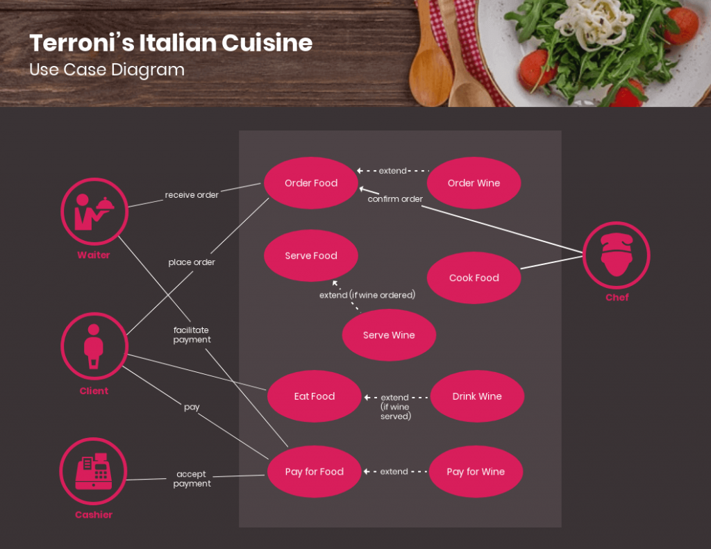
This use case diagram can be particularly helpful to restaurants or fast-food chains in terms of systemizing routine processes and presenting day-to-day activities to employees in a simpler and more orderly way.
Travel use case diagram
Here is a use case diagram that maps out how different types of users can engage with a travel booking website or application.

This comprehensive template includes extended use cases marked by dotted lines and arrows instead of simple lines. It can be scaled down or up for hotels, airlines, and other travel reservation systems.
Banking use case diagram
Designed for automated teller machine (ATM) systems, this use case diagram portrays different types of transactions as use cases.

As this example is very simple and contains only essential elements, it can be adapted for other banking systems like branch banking or online banking.
Consumer electronics store use case diagram
Last but not least, this use case diagram example illustrates how sales and management teams can use a retail system to carry out tasks.

It can be applied to retail systems for consumer electronics and home appliances, fast-moving consumer goods, and other retail sectors.
Ready to master use case diagrams? Check out our blog for everything you need to know and more use case diagram examples for your inspiration.
Use case diagrams can aid your development process with the following benefits:
- Guiding development: Use case diagrams can help establish the cost and complexity of your system. It does so by specifying which functions become requirements that will make it to the development stage.
- User-driven approach: Use case diagrams are written in natural language, which helps users easily understand them. Additionally, they provide businesses an excellent way to communicate with customers. Here is a use case diagram example that shows the basic transactional path of a banking customer:

- Simplifying solutions: By breaking down solutions into practical functions or features, use case diagrams can decrease the complexity of the problem that your system is trying to solve.
- Tracking progress: Use case diagrams can be used to monitor which use cases have been implemented, tested, and delivered and help you identify which functions work and which ones don’t.
Create use case diagrams that are easy to understand with Venngage’s extensive icon library. We offer 40,000+ icons, including diverse people icons, so your diagrams can reflect your users more accurately.
Double-click an icon in your chosen template, and choose from the options in the menu.
There are many different types of diagrams that can be used for designing and representing systems and processes. As for UML use case diagrams, they are classified into two types: behavioral and structural UML diagrams.
Behavioral UML diagrams
Behavioral UML diagrams provide a standard way to visualize the design and behavior of a system. Under them are 7 other types of diagrams which are:
- Activity diagrams
- State machine diagrams
- Sequence diagrams
- Communication diagrams
- Interaction overview diagrams
- Timing diagrams
- Use case diagrams
As an example, this use case diagram portrays how an ATM system will behave or react when a customer or administrator performs an action.

Structural UML diagrams
Structural UML diagrams on the other hand focus on depicting the concepts involved in a system and how they relate to each other. There are also 7 types of structural UML diagrams:
- Class Diagram
- Component Diagram
- Deployment Diagram
- Object Diagram
- Package Diagram
- Profile Diagram
- Composite Structure Diagram
Use case diagrams contain a combination of different elements and specialized symbols and connectors. Whether you want your use case diagram to be simple or in-depth, it should include the following basic components:
- Actors – An actor is anyone who performs an action using your system. Actors or users can be a person, an organization, or an external system. Actors are represented by stick figures in a use case diagram. In this example, the functions of a system are modeled for two types of actors: persons and organizations.

- System – The system scope covers a sequence of actions and interactions between users and the system. To depict the system boundary, system boundary boxes are used to signify that a use case is within the scope of the system.
- Use cases – Use cases are the different uses or applications that your system can offer users. Horizontally shaped ovals are used to symbolize use cases while lines are drawn to connect the user to the use case. Here is an example to illustrate the relationship between users and use cases:

- Goals – The goal is the end result of a use case. An effective use case diagram should describe the activities involved in reaching the goals behind each use case.
What is included and not included in a use case diagram?
Use case diagrams describe the relationship between the users, the system, and its use cases. They do not need to go into a lot of detail and explain how the system operates internally. Here is a guide on what to include and what not to include in your use case diagram:
What to include:
- Who is using the system
- How the user will use the system
- What the user’s goal is
- What steps the user takes to accomplish a task
- How the system responds to a particular action
What not to include:
- The order in which steps are performed
- Details about user interfaces
- Programming language
When to apply use case diagrams
Here are some situations where applying use case diagrams can be particularly useful:
Early stages of system development:
- Gather and visualize requirements: Capture the needs and goals of different user groups and how the system interacts with them.
- Define system scope: Ensure you’re building the right features and functions based on user needs.
- Identify potential issues: Spot inconsistencies or missing functionalities early on in the development process.
Communication and collaboration:
- Explain system functionality to stakeholders: Offer a clear and concise visual representation of what the system does and how it works.
- Facilitate discussions and feedback: Use the diagram as a starting point for discussions and encourage user input into the design process.
- Align teams on system goals: Ensure everyone involved has a shared understanding of the user experience and system objectives.
Testing and documentation:
- Derive test cases: Use the diagram to identify different use cases and scenarios to test the system functionality.
- Document system behavior: Provide a clear and easily understandable reference for future maintenance and updates.
- Support ongoing communication: Explain complex system features to new team members or users.
Beyond these situations, consider using use case diagrams when:
- You want to focus on the “what” and “why” instead of the technical details.
- You need to deal with multiple user types with different needs and functionalities.
- You want to increase understanding and agreement among stakeholders.
How do you write a use case diagram?
Writing a use case diagram involves deconstructing processes in order to reveal a basic overview of your system. Here are some steps that you can follow:
Step 1: Identify the actors (users) who are going to be engaging with your system. Categorize each type of user based on their roles.
Step 2: Pick one type of user and list what actions they would take using the system. Each action becomes a use case.
Step 3: Create a goal for every use case. Identify what is required from the system to achieve these goals.
Step 4: Structure the use cases. Include in the description for each use case the basic course of events that will happen when a user performs a certain action. It should describe what the user does and how the system responds.
Step 5: Take into consideration alternate courses of events and add them to extend the use case.
Step 6: Repeat steps 2-5 to create a use case diagram for each type of user.
What software is used to create a use case diagram?
There are various tools and software available for creating a use case diagram. For starters, you can try Microsoft Visio which is a diagramming and vector graphics application that is part of the Microsoft Office family.
You can also go for web-based software if you don’t want the hassle of downloading, installing, and updating programs. Venngage’s diagram features include pre-made use case diagram templates that you can customize for your business and development needs.
Don’t guess, visualize: Use case diagrams map how you gain from this system
Creating a use case diagram can help you illustrate how your system can fulfill the needs and goals of your users. Make sure to use Venngage’s diagram maker to create a successful use case diagram for your next project.
Discover popular designs

Infographic maker

Brochure maker

White paper online

Newsletter creator

Flyer maker
Timeline maker

Letterhead maker
Mind map maker

Ebook maker
Cookies on GOV.UK
We use some essential cookies to make this website work.
We’d like to set additional cookies to understand how you use GOV.UK, remember your settings and improve government services.
We also use cookies set by other sites to help us deliver content from their services.
You have accepted additional cookies. You can change your cookie settings at any time.
You have rejected additional cookies. You can change your cookie settings at any time.
- Education, training and skills
- Further and higher education, skills and vocational training
- Sector-based Work Academy Programme: qualitative case study research
- Department for Work & Pensions
SWAP Qualitative Case Study Research: Annexes
Updated 16 May 2024

© Crown copyright 2024
This publication is licensed under the terms of the Open Government Licence v3.0 except where otherwise stated. To view this licence, visit nationalarchives.gov.uk/doc/open-government-licence/version/3 or write to the Information Policy Team, The National Archives, Kew, London TW9 4DU, or email: [email protected] .
Where we have identified any third party copyright information you will need to obtain permission from the copyright holders concerned.
This publication is available at https://www.gov.uk/government/publications/sector-based-work-academy-programme-qualitative-case-study-research/swap-qualitative-case-study-research-annexes
Annex 1: SWAP Theory of Change Logic Model
The flow diagram presents the following information:.
Inputs mainly under the heading ‘Government (Continued benefits, training costs, barriers to participation, analytical resources)’:
‘Employer -Time for set up/management/ feedback’
‘Training Provider - Time for set up/management’
‘Employer Advisor’, ‘Work Coach’
These inputs flow into the following activities:
- ‘Local Labour market analysis’
- ‘Arrange SWAP ’
- ‘Disseminate available SWAP with JCP ’
- ‘Awareness of available SWAP ’
- ‘Sell SWAP to claimant’
- ‘Refer claimant’
These activities flow to the output: ‘Claimant agrees to participate in SWAP ’. The claimant agreement flows on to the claimant input: ‘Investment of time and initial travel costs (reimbursable)’ and the following work coach activities:
- ‘Barrier Assessment’
- ‘Record referral’
Then the following employer activities:
- ‘Background checks (if applicable)’
- ‘Workplace adjustment (if applicable)’
These all flow into the output ‘Claimant starts SWAP ’.
The main SWAP portion of the theory of change starts here with the activities:
- ‘Pre-employment Training’ (with side flow to ‘Claimant gains certification (if applicable)’)
- ‘Work placement’
- ‘Guaranteed Interview’
The main SWAP activities flow to the following three possible outputs:
- ‘Claimant completes SWAP : Interview successful’
- ‘Claimant completes SWAP : Interview unsuccessful’
- ‘Claimant does not complete SWAP ’)
Regardless of which output, the diagram shows a flow to the activity ‘WC completes SWAP Tracker’.
If Claimant completes SWAP with an unsuccessful interview, or the Claimant does not complete the SWAP , these outputs flow into the short term outcome of ‘additional needs identified’. The unsuccessful interview also flows into the short term outcome ‘interview feedback from employer’.
Both of these short term outcomes flow into the activity ‘Reflection with WC’ and this can flow into the activity ‘Claimant applies for other jobs in sector’. Claimant applies for other jobs in sector can flow into a successful short term outcome ‘claimant gains employment in new sector’ or an unsuccessful short term outcome, in which case ‘claimant reengages with WC’.
Claimants unsuccessful at SWAP or subsequent interviews (through engagement with WC activities) flow into either:
- the short-term outcome ‘Increased employability’
- the medium term outcome ‘improve claimants employability’.
Collectively the short and medium term outcomes flow into the impact ‘Value for unsuccessful claimants’.
If the claimant is successful at either the guaranteed or subsequent interview, these flow into the output ‘ Claimant enters work in new sector’ which flows onto the following four short-term outcomes:
- ‘Change in attitude towards working in new sector’
- ‘Claimant has skills to succeed at new job’
- ‘Increased earning’
- ‘Reduced UC /benefit’
This may flow into the following medium term outcomes:
- ‘ UC ends (or is maintained at reduced level)’
- ‘Sustained employment (18 months)’
- ‘Career progression’
These medium term outcomes flow into the impacts:
- ‘Increased employment’
- ‘Reduced UC costs’
If the claimant is successful at the guaranteed interview, and subject to the assumption ‘Employer outputs and outcomes are dependent on the SWAP meeting employer expectations’, the following employer outputs are recorded:
- ‘Reduced vacancies’
- ‘Employer social responsibility goals met’
- ‘Development of local workforce’
‘Reduced vacancies’ and ‘Employer social responsibility goals met’ flow to the short-term outcome ‘Employer satisfied with SWAP experience’. This then flows to the activity ‘ DWP gathers feedback from claimants and employers’ and the short-term outcome ‘Collated employer success stories’.
These short-term outcomes flow to the medium term outcomes:
- ‘Businesses return for additional SWAP ’
- ‘Increased employer uptake in SWAP or other provisions’
- ‘Improved Attitudes towards hiring DWP claimants’
- ‘Employers approaching DWP with vacancies more readily’
‘Development of local workforce’ output flows to the following short-term outcomes:
- ‘ SWAP aligns with local market need including sector shortages’
- ‘Sector pathways identified’
- ‘Change in attitude towards working in new sector’, which flow to the medium term outcome ‘Improved fit between employers and claimants’.
Medium term outcomes in this employer focussed part of the theory of change flow to the impacts ‘Improved DWP relationship with business sector’ and ‘increased employment’.
Annex 2: Participant characteristics
Table 3: employer, training provider and claimant participants by swap sector, table 4: claimant participant characteristics, annex 3: additional methodology details.
This annex includes additional information about how the case study research was conducted.
Contacting claimants
A random sample of 150 claimants was drawn for each case study area (600 claimants in total across the four areas) in order to achieve 10 claimant interviews in each district. This sample size was in line with previous, similar research (in terms of mode, length and recruitment approach), which achieved a response rate of approximately 1 in 15 claimants. The sample was sourced from the SWAP manual trackers completed by each district which detail which claimants are referred each week to the programme. Claimant identification numbers were then linked to centrally held contact information (for example, postal address and telephone number).
The stratification of the sample was limited by the quality of data DWP holds on certain claimant characteristics (for example, ethnicity and disability information was not available) as well as claimants’ SWAP journey (only claimant start dates on the pre-employment training ( PET ) were consistently recorded by all areas). As a result, it was impossible to identify in advance claimants who had dropped out of a SWAP part-way through, or claimants who were successful at the guaranteed interview stage, which limited the study’s ability to explore these aspects in detail. The sample drawn was, therefore, broadly reflective (rather than representative) of the claimant population who started on a SWAP in terms of gender and sector of SWAP , and consisted of individuals who had started the SWAP PET within the previous 12 weeks of the sample being drawn. This time period was agreed in order to ensure the feasibility of obtaining a sample of 150 claimants from each area, while minimising as much as possible the risk of recall bias within claimant accounts of their experience.
It is important to note the claimant sample was delivered in two separate stages, to reflect the gap in fieldwork between Area 2 and Area 3. The samples for Areas 3 and 4, was additionally stratified by age (18 to 24 years vs. 25+ years) to account for the small number of potential participants aged 18 to 24 years provided in the sample for Areas 1 and 2.
All claimants in the sample were sent an advance letter to the address held on DWP ’s central records. This letter provided further information about the research, what their participation would involve, data processing information and an email address to which they could write if they wanted to opt-out. Claimants were called using the telephone numbers provided in each sample, and while formal quotas for recruiting participants were not used, calls were targeted to achieve a spread in terms of claimant gender, age and sector of SWAP (the latter was obtained from the SWAP manual trackers and was therefore dependent on DWP staff interpretations of this at the local level). Claimants were called up to three times without a response before they were not contacted any further. During the calls, researchers emphasised their independence from benefits processing and that decisions regarding participation would not affect claimants’ benefits in any way. Each interview lasted approximately 30 to 45 minutes and claimants received a £20 voucher for their time.
In Area 4, fieldwork was terminated early due to an underlying issue with this sample in which few claimants could be contacted (many claimants did not pick up the phone) and of those who did, few recalled the programme or had actually started the SWAP to which they had been referred. Only two interviews were completed from 207 recruitment calls, compared to 10 interviews completed from 88 recruitment calls in Area 3. The study team attempted to unpick the reasoning for the issues with the underlying sample in subsequent meetings and interviews with the local operational contacts, however, it was difficult to pinpoint this exactly. The information gathered suggested that the issue was likely a result of error(s) completing the local manual SWAP trackers. As a result, fieldwork was terminated early so that the findings could be reported to the timetable agreed.
Contacting employers and training providers
As described in the main report, the study was reliant on the case study areas to supply the contact details of employers and training providers who had taken part in a SWAP in their districts, as there was no alternative way of identifying these organisations. Within each area, the study aimed to interview a total of 7 employers, and 3 training providers, and so local contacts were asked to provide approximately 15 to 20 employer contacts and 5 to 10 training provider contacts to account for uncertainty in likely response rates. Obtaining contacts was more difficult in some of the case study areas and was affected by factors such as local record keeping of this information (for example, some training providers were listed as employers, and other contact information was out of date), and busyness of the staff involved. In all areas, subsequent samples of employers were requested due to poor response rates for this participant group.
To counter the risk of staff supplying only contacts for similar organisations, and therefore similar experiences of the programme, contact information for a range of organisations in terms of key characteristics (size, sector of SWAP , length of SWAP , number of SWAPs involved in, and how the SWAP was initiated) was requested. Organisations were then approached by researchers to ensure a spread across these characteristics, although achieving this was limited by response rates, particularly among employers.
Organisations were initially emailed using a template which explained the purpose of the research and asked if they were able to participate. Where organisations agreed to take part, they were then sent an additional information sheet and booked in for an interview at a convenient date and time. Where no response was received, a follow-up email was sent a few days later prompting them about the study. Finally, where the target number of interviews had not yet been reached, organisations were contacted by telephone for up to a maximum of two attempts. Where this was the case, the researcher verbally communicated the key information about the study contained in the initial emails.
For most areas, the first time employers and training providers heard about the research was when they were contacted via email about the study. In Area 4, however, DWP staff approached employers in advance before handing contact details over to the study team. This approach was taken as DWP staff in this area felt it would be beneficial in securing employer participation and minimised any risk to their relationships with these contacts if the study team were to contact them without warning. It should be noted that this may have increased the risk that some employers may have felt obligated to take part in the research and/or restricted their feedback due to a perceived lack of separation between DWP researchers and operational staff leading on SWAPs . As with all areas, researchers in Area 4 emphasised their independence from jobcentres ( JCPs ) and SWAP policy decision-making during each contact with participants, and the questions asked during data collection were framed in a way to encourage and enable participants to be honest about their experience. Despite this, it’s likely that a certain level of bias related to this aspect remains in the dataset obtained.
Each interview lasted approximately 30 minutes to an hour, depending on how much each organisation wanted to share. To ensure the most appropriate person was spoken to, the information shared during the recruitment stages requested that the participant was an individual who had knowledge of, or was responsible for, the SWAP that their organisation had been involved in.
Contacting staff
Once JCP Service Leaders had agreed for fieldwork to take place in their district areas, the study team were signposted to operational staff who would be able to facilitate the research. These individuals became key contacts for the study team during fieldwork. In initial meetings, these local contacts provided a broad overview of the SWAP set-up in their district, and the types of staff involved in delivery, from which a list of different staff roles to speak to as part of the fieldwork was agreed. Due to the varying nature of the local staffing models, it was easier to understand how SWAP delivery was organised in some areas more than others.
The project manager and case study leads maintained regular contact with these local contacts while fieldwork took place in each area. In Areas 1 and 2 this mostly consisted of contact via email, whereas for Areas 3 and 4 this took the form of a weekly scheduled meeting. In Areas 2, 3 and 4, a follow-up meeting took place with the local contacts to check the study team’s understanding of local SWAP delivery obtained through data collection, and to clarify any aspects of delivery that remained unclear.
The local contacts provided a list of suggested staff who could be approached for the fieldwork based on their role and involvement in local SWAP delivery. The study team then arranged the interviews and focus groups for these staff around their availability. In setting up the interviews and focus groups, an information sheet was provided about the research, and it was emphasised that their participation was voluntary. Despite this, some staff may have only participated in the study because they felt obligated to. As with other participant groups, the independence of the study team was emphasised, and participants were offered the opportunity to withdraw from the study if they wanted to.
Piloting [footnote 1] interviews were conducted with two members of DWP staff, one employer and one training provider who agreed to this. These interviews were conducted to test the length and appropriateness of the topic guides for these participant groups, and the quality of the data obtained. These individuals were recruited from a separate JCP district to the case study areas and so the information collected was not used in the analysis and reporting of this study. The topic guides were amended following these pilots.
For claimants, the first week of fieldwork was considered a pilot. Minimal changes were made to the topic guide following these interviews, and so, unlike the other fieldwork strands, the data collected during these interviews was analysed and reported on. It should, however, be noted that the topic guides and fieldwork processes were continually reviewed and modified throughout the data collection periods to ensure they were as efficient and effective as possible. The study team met multiple times a week to reflect on interviews, and formal debrief sessions were held within the study team, and separately with wider supporting researchers, following the end of data collection in each study area. This process allowed learning from each area to be implemented in subsequent fieldwork.
Analysis and Reporting
Once all interviews had been conducted, the interview notes formed the final dataset. The dataset was explored using a thematic analysis approach. As there were multiple researchers involved in the coding of the data, a coding framework (Annex 4) was developed to ensure consistency in coding across the study team. The research questions were used as a guide to ensure the framework aligned with the objectives of the research, and the framework was tested with an initial sample of interviews before a final version was agreed for coding the rest of the data (although this was still subject to ongoing tweaks as coding progressed).
Members of the study team were paired up to code a specific strand of data (for example, employers) and each pair coded the same initial set of notes to check alignment in their coding approach, before separately coding the remaining data. A separate member of the study team then examined a selection of coded notes from each pair to quality assure the completed coding. Feedback on the coding approach, particularly inconsistencies within each pair, was provided to the coders so that this could be incorporated into the analysis of future notes.
The project team met multiple times to discuss and agree the themes identified within the coded data. The themes identified via this process of analysis structured the findings within this report. When analysing the data, findings were explored by participant group (for example, claimants vs. employers) as well as by case study area (for example, Area 1 vs. Area 2), and these were included in the reporting where relevant.
A Quality Assurance ( QA ) panel was established to review the work of the research team during the analysis stage. The panel included researchers external to the project, senior researchers, and a fieldworker external to the study team, who was involved in conducting the research. This panel was engaged to review the initial coding framework that had been developed, and again to review how the codes had been applied to a sample of the data collected. This ensured that the approach taken to analysis had been peer reviewed, and that the data analysis conducted was of good quality. The final report was separately quality assured by an academic on secondment to the In-House Research Unit ( IHRU ), as well as senior researchers in the unit.
Annex 4: Initial coding framework
A pilot is a small-scale, preliminary study that is used as a test run for a particular research instrument to ensure its efficacy. ↩
Is this page useful?
- Yes this page is useful
- No this page is not useful
Help us improve GOV.UK
Don’t include personal or financial information like your National Insurance number or credit card details.
To help us improve GOV.UK, we’d like to know more about your visit today. Please fill in this survey (opens in a new tab) .
IMAGES
VIDEO
COMMENTS
Activity diagrams can be used to model business requirements, create a high-level view of a system's functionalities, analyze use cases, and for various other purposes. In each of these cases, here's how to draw an activity diagram from the beginning. Step 1: Figure out the action steps from the use case
Table of Contents hide 1 What is an Activity Diagram 1.1 Understanding the Relationship Between Use Case Descriptions and Activity Diagrams 1.1.1 Use case and Use Case description 1.2 Elaborating an use case with Use Case Description 2 An Example - Online Shopping Cart System 2.1 Problem Description: 2.2 Create a Use Case Diagram for […]
2. Document management process activity diagram. As we have previously mentioned, activity diagrams can also be used to model business processes. In this example, an activity diagram is used to portray the steps involved in the process of creating a formal document: 3. Construction process activity diagram.
Activity Diagram for module 2 of case study 1 . scenario-based activity diagram . Activity Diagram for module 1 of case study 2. The user can search books, viewbooks Without any fee but can download the Book only and only if he pays money. Provide the facility of managing the cart To the user, so that he can update his cart.
This activity diagram shows the process of logging into a website, from entering a username and password to successfully logging in to the system. It uses different container shapes for activities, decisions, and notes. Lucidchart is the ideal tool for creating any kind of UML flowchart, whether it's an activity diagram, a use case diagram ...
An Activity Diagram is one of the behavioral diagrams in UML, used to model the dynamic aspects of a system. It focuses on illustrating the workflow or sequence of activities, actions, and decisions within a system or a process. These diagrams are particularly useful for modeling business processes, software algorithms, and workflow scenarios ...
Activity Diagrams are used to illustrate the flow of control in a system and refer to the steps involved in the execution of a use case. We can depict both sequential processing and concurrent processing of activities using an activity diagram ie an activity diagram focuses on the condition of flow and the sequence in which it happens. We ...
Once you've enabled the UML shape library, add shapes by selecting a symbol from the sidebar and then dragging and dropping it right onto the canvas. For an activity diagram, you'll want to begin by dragging out the start node—a black circle—from the toolbox. Refer to this page featuring all the common UML activity diagram symbols and ...
In this article, I will cover how to build activity Diagrams using the case study we started last week. A UML diagram is a diagram based on the UML (Unified Modeling Language) with the purpose of…
An activity diagram visually presents a series of actions or flow of control in a system similar to a flowchart or a data flow diagram. Activity diagrams are often used in business process modeling. They can also describe the steps in a use case diagram. Activities modeled can be sequential and concurrent. In both cases an activity diagram will ...
Activity Diagrams for Use Case Modelling 23 How to construct Activity Diagrams 1.Finding system Actors, Classes and use cases 2.Identifying key scenarios of system use cases 3.Combining the scenarios to produce comprehensive work ows described using activity diagrams 4.Where signi cant object behaviour is triggered by a work ow, adding object
This UML activity diagram template can help you: - Describe what must happen in the system being modeled. - Illustrate a business process or workflow between users and the system. - Improve any process by clarifying complicated use cases. Open this template to view a detailed example of a UML activity diagram that you can customize to your use case.
An activity diagram in UML (Unified Modeling Language) is a type of diagram used to represent the dynamic aspects of a system, business process, or workflow. It focuses on modeling the flow of activities, actions, and decisions within the system or process. Activity diagrams are particularly useful for understanding the order of execution ...
In this video, you're going to learn1. What is the Activity Diagram? 2. How to draw an activity diagram? 3. Step by step with examples. One of the other imp...
UML - Activity diagram case studyWatch more Videos at https://www.tutorialspoint.com/videotutorials/index.htmLecture By: Mr. Arnab Chakraborty, Tutorials Poi...
Ticket vending machine. Purpose: An example of UML activity diagram describing behavior of the Purchase Ticket use case for a Ticket vending machine.. Summary: Activity is started by Commuter actor who needs to buy a ticket.Ticket vending machine will request trip information from Commuter. Based on the info machine will calculate payment due and request payment options.
Activity diagram is an advancement of a flowchart that contains some unique capabilities. Activity diagrams include swimlanes, branching, parallel flow, control nodes, expansion nodes, and object nodes. Activity diagram also supports exception handling. To draw an activity diagram, one must understand and explore the entire system.
Activity Diagrams describe how activities are coordinated to provide a service which can be at different levels of abstraction. Typically, an event needs to be achieved by some operations, particularly where the operation is intended to achieve a number of different things that require coordination, or how the events in a single use case relate ...
11 UML Diagram Examples: Class, Activity, and More. A UML diagram is the visual blueprint of software and business processes, using the Unified Modeling Language as its foundation. This diagram plays a pivotal role in object-oriented design, capturing the essence of both static structure and dynamic behavior within software systems.
The objective of this Systematic Mapping Study (SMS) was to collect and classify the current body of. evidence regarding test case generation approaches using the Unified Modeling Language (UML ...
The sequence diagram has four objects (Customer, Order, SpecialOrder and NormalOrder). The following diagram shows the message sequence for SpecialOrder object and the same can be used in case of NormalOrder object. It is important to understand the time sequence of message flows. The message flow is nothing but a method call of an object.
An approach is proposed in [16] to manually transform exceptional use cases into extended activity diagrams. Special stereotypes (e.g., <<failure>>and <<handler>>) are introduced to specify exceptional handling concepts. Visual Paradigm [22] and CaseComplete [6] can automatically transform flows of events of a use case into an activity diagram.
Each action becomes a use case. Step 3: Create a goal for every use case. Identify what is required from the system to achieve these goals. Step 4: Structure the use cases. Include in the description for each use case the basic course of events that will happen when a user performs a certain action.
The flow diagram presents the following information: ... the diagram shows a flow to the activity 'WC ... Obtaining contacts was more difficult in some of the case study areas and was affected ...