- Open access
- Published: 02 June 2022

SRR metamaterial-based broadband patch antenna for wireless communications
- Preet Kaur ORCID: orcid.org/0000-0002-1125-3201 1 ,
- Sonia Bansal 1 &
- Navdeep Kumar 2
Journal of Engineering and Applied Science volume 69 , Article number: 47 ( 2022 ) Cite this article
3827 Accesses
6 Citations
Metrics details
This paper presents the design and analysis of a broad-band patch antenna using split ring metamaterial. The SRR metamaterial structures are embedded in a unique and novel way in the patch antenna, so that subwavelength modes get introduced in the patch cavity and a broad bandwidth antenna with good performance characteristics is obtained. A rectangular microstrip patch antenna is taken as a reference antenna, which resonates at a frequency of 5.2 GHz and has an impedance bandwidth of 70 MHz. To improve the bandwidth of the patch antenna, firstly the split ring resonator (SRR) is designed according to the reference patch antenna. The optimized SRR metamaterial is placed in between the patch and ground plane of the proposed antenna. The – 10 dB impedance bandwidth of the metamaterial-embedded proposed antenna is 1.63–4.88 GHz and has an average gain of 4.5 dB. The Prototype of the proposed antenna and reference antenna is fabricated and experimental results are obtained. Experimental and simulated results are in good agreement. The presented antenna can be used for LTE, GSM, WiMAX, Bluetooth, and other wireless applications.
Introduction
In modern days, with the advancement in the wireless and electronics industry need for compact, broadband, high-gain, directional and low-cost antennas has increased very much because the antennas are the vital components in wireless communication system [ 1 ]. Patch antennas are low profile, have a simple geometric structure with the ability of easy fabrication on PCB and can be easily integrated with other wireless devices. So, these antennas are suitable for current wireless technology [ 2 ]. But one of the limitations of these antennas is narrow bandwidth. The bandwidth of patch antenna can be improved by embedding different shapes such as U shape and W shape in its ground plane [ 3 ], using a parasitic patch [ 4 ] and increase of substrate thickness. These techniques improve the bandwidth, but it reduces the efficiency of the antenna. Many other approaches like the slotted patch antenna technique, defected ground structures, merging of resonant modes [ 5 ], slotted array technique [ 6 ], and suspended techniques [ 7 ] are proposed in the literature. But these approaches have disadvantages of less improvement in bandwidth, complex structure, cross-polarization and impedance matching.
During the last few years, metamaterials have been the intense area of research in antenna design to improve antenna performance [ 8 , 9 , 10 , 11 , 12 , 13 ]. Metamaterials are artificial materials that exhibit properties that do not exist in naturally occurring materials. To improve the bandwidth of patch antenna different types of metamaterial [ 14 , 15 , 16 , 17 , 18 ] has been used by antenna designers for improving the bandwidth. A MIMO antenna with four ports is proposed by Xia Cao et al. [ 19 ] using a slotted square ring metamaterial structure to improve the bandwidth. Metamaterial-based imaging structure for wireless frequency range is presented in [ 20 ]. But the limitation of techniques used in these research works is that it improves the bandwidth, but it reduces the other performance parameters of the antenna and has complex antenna structures.
The main aim of this paper is to design a novel broadband patch antenna using metamaterial without degrading the other performance parameters of the antenna. The proposed technique in this paper uses 11 layers of SRR type MNG type metamaterial which are embedded between patch and ground plane. These SRR metamaterial structures are embedded in a unique and novel way in the patch antenna to improve the bandwidth of the reference patch antenna and make it broadband. The proposed patch antenna has wide bandwidth with good performance characteristics.
Design of reference antenna
A low-cost FR4 epoxy substrate with dielectric constant εr = 4.4 and loss tangent δ = 0.0025 is chosen for designing of reference antenna. The antenna is modeled and optimized in HFSS software. The optimized geometric parameters of the reference antenna are presented in Fig. 1 and fabricated antenna is presented in Fig. 2 . From Fig. 3 , it can be seen that the reference antenna resonates at a frequency of 5.2 GHz with a − 11.68 dB reflection coefficient (S11) and has a 70-MHz narrow impedance bandwidth. Figure 4 shows the measured and simulated gain in dB. The antenna has a gain of 4.02 dB at resonating frequency. The main drawback of this antenna is that it has a very narrow bandwidth and less return loss, which is not suitable for current wireless applications. So, SRR metamaterial is used in this paper to improve the bandwidth and overall performance of the antenna.

Geometric structure of optimized reference microstrip patch antenna

Fabricated reference patch antenna

Measured and simulated reflection coefficients of reference patch antenna

Measured and simulated gain of reference patch antenna
Design and analysis of unit cell of split ring resonator
A split ring resonator (SRR) comprises two concentric rings of copper printed on substrate material. Geometric parameters of SRR are presented in Fig. 5 a. Excitation of SRR with external magnetic field causes the current to flow from one ring structure to other through the slot between them. So, there is flow of very strong displacement current in this structure. The slots in SRR behaves like distributed capacitance and it behaves like LC circuit. The equivalent circuit of unit cell of SRR is presented in Fig. 5 b. In equivalent circuit, metallic ring structures are modeled by inductance L and capacitance C = Co/4 (Co/2 = capacitance due to single ring and structure behaves like LC circuit having resonant frequency given below as:

a Geometric structure of unit cell of SRR, Rout = 3 mm, Rin = 2.8 mm, w = 1 mm, s = 1 mm, S L = 10 mm, S w = 10 mm, b Equivalent circuit of unit cell of SRR
SRRs effective permeability can be given as
Unit cell of split ring resonator is modeled and simulated in HFSS as shown in Fig. 6 . For simulation of SRR metamaterial unit cell boundary conditions are used. Repeated unit cell boundary conditions are applied along x and y direction ( xy plane) and wave ports are applied in z direction as shown in Fig. 6 . The S parameters of optimized SRR structure are calculated and then permeability and permittivity are extracted from S parameters using the Eqs. ( 3 – 6 ).

Simulation model of unit cell of SRR (Unit cell boundary conditions are applied along x and y direction and wave ports are applied in z direction)
Real value of permeability (μ r ) and permittivity (ϵ r ) is shown in Fig. 7 . From permeability and permittivity graph it can be analyzed that real part of permeability of SRR at 5.4 GHz is negative and real part of permittivity is positive and maximum at his frequency, so this is MNG type resonating metamaterial. Refractive index ( \(n=\sqrt{\mu \varepsilon\ }\Big)\) is product of permittivity and permeability and is negative in this range. Figure 8 a, b shows E-field and the H-field of SRR structure. It shows that when SRR is excited with external magnetic field, it causes the current to flow from one ring structure to other through the slot between them. Hence there is a flow of strong displacement current in SRR structure.

Real permittivity and permeability of split ring resonator

a E-field of SRR structure. b H-field of SRR structure
Design and fabrication of proposed SRR-embedded patch antenna
For designing a broad-band antenna, optimized unit cell of SRRs is placed in between the patch antenna and ground plane. For this, the reference antenna substrate thickness is divided in two parts of 0.8 mm. The exploded view of SRR-embedded antenna is presented in Fig. 9 . Each layer of metamaterial placed under patch consist of four-unit cell of SRR.

Exploded view of proposed metamaterial (single layer)-embedded patch antenna in HFSS
The optimized SRR-embedded antenna consists of 11 layers of metamaterial to achieve maximum bandwidth.
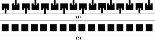
The optimized and designed SRR-embedded antenna is fabricated using PCB prototyping machine. Figure 10 presents the fabricated SRR layer and Fig. 11 presents the fabricated proposed SRR-embedded patch antenna with 11 layers of metamaterial.

Fabricated single layer of metamaterial with four SRRs metamaterial

Fabricated proposed antenna with metamaterial layers placed under it
Results and discussion
Simulation and measured results of proposed srr-embedded patch antenna.
The proposed SRR antenna presented in Fig. 11 is simulated and optimized in HFSS. Reflection coefficient of fabricated antenna is measured using vector network analyzer (VNA). The gain and radiation patterns of antenna are measured in anechoic chamber. As the SRR is placed under patch, subwavelength modes get introduced in the patch antenna. Effect of adding the different layers of SRR underneath the patch is studied extensively in this paper. Addition of three layers under patch cause the patch to resonate at 3.8 GHz with impedance bandwidth of 80 MHz as presented in Fig. 12 . The antenna has gain of 4.05 dB at this frequency as presented in Fig. 12 . As the more layers of SRR is embedded under the patch it causes more modes to get introduced in patch antenna and resonant frequency also shift towards the lower side. Addition of five layers increases the bandwidth of patch antenna from 80 MHz to 150 MHz and addition of nine layers introduces one mode at frequency of 1.8 GHz and other two modes at 3.5 GHz and 4.5 GHz as presented in Fig. 13 .

Reflection coefficient and gain of three layers of SRR metamaterial-embedded antenna

Reflection coefficient of five and nine layers of SRR metamaterial-embedded antenna
When 11 layers of SRR is added all the three modes introduced by nine layers of metamaterial get merged and broad-bandwidth of 3.25 GHz is obtained. Figure 14 shows the simulated and measured reflection coefficient graph of proposed antenna with 11 layers of metamaterial. From this graph, it can be seen that antenna resonates between 1.62 GHz and 4.87 GHz and it covers the wide bandwidth of 3.25 GHz. The return loss of this proposed patch antenna improves from − 11.68 dB to − 25.2 dB and has average gain of 4.5 dB in the resonating frequency range of 1.63 GHz to 4.88 GHz as shown in Fig. 15 . Addition of more layers of metamaterial underneath the patch does not show further improvement in results. Hence, the proposed antenna has 11 layers of SRR under the patch. This antenna has good average gain of 4.5 dB in the entire resonating frequency range. Figure 16 presents the simulated and measured E-plane and H-plane radiation pattern of this antenna at 3.5 GHz. Proposed and reference antenna has almost same radiation pattern in both planes.

Simulated and measured reflection coefficient of proposed antenna with 11 layers of metamaterial

Simulated and measured gain of proposed antenna with 11 layers of metamaterial

Simulated and measured E plane ( a ) and H plane ( b ) radiation pattern of proposed antenna
Table 1 provides the comparison of various performance parameters of the reference antenna and proposed antenna. The conventional reference patch antenna produces a limited impedance bandwidth of 70 MHz. The SRR metamaterial improves the bandwidth of patch antenna significantly from 70 MHz to 3.25 GHz. Thus, bandwidth is multiplied by 46.42, which is huge improvement in bandwidth. The return loss of antenna also improves after embedding metamaterial and proposed antenna also has good gain in resonating frequency range. Due to introduction of various subwavelength modes in metamaterial-embedded antenna resonant frequency of reference antenna get shifted to lower frequency range of 1.63 GHz to 4.88 GHz from 5.4 GHz. All these subwavelength modes get merge and give rise to broad-bandwidth. Table 2 shows the comparison of proposed work with the other similar works. As per comparison, this can be concluded the embedding of SRR layer using proposed method gives significant improvement in bandwidth and designing and fabrication of proposed antenna is also very simple.
Conclusions
Developments of electronic warfare system and wireless communication in modern fast developing technologies include the use of metamaterial in antenna system for improving the performance of overall system. A broadband metamaterial-embedded antenna is proposed in this paper to adjust with current wireless systems. The presented antenna covers the frequency band of 1.63 GHz to 4.88 GHz is designed, analyzed and measured in this research paper. Simulated results shows that the presented antenna has bandwidth of 3.25 GHz (1.63–4.88 GHz) and the experimental results are close to simulated one. The proposed antenna has significant bandwidth and has average gain of 4.5 dB. The other advantages of proposed antenna are that it is cheap, simple, can be easy fabricated with PCB machine and can be integrated with other wireless devices. The presented antenna can be used for LTE, GSM, WiMAX, Bluetooth, and other wireless applications.
Availability of data and materials
The datasets generated during and/or analyzed during the current study are available from the corresponding author on reasonable request.
Abbreviations
Epsilion NeGative
Global System for Mobile Communications
High-frequency structure simulator
Long-term evolution
Printed circuit board
Split ring resonator
Worldwide Interoperability for Microwave Access
Bougoutaia T, Khedrouche D, Hocini A (2016) Bandwidth improvement for compact microstrip patch antenna using metamaterials. Acta Phys Pol A 129:538–540. https://doi.org/10.12693/APhysPolA.129.538
Article Google Scholar
Kumar A, Saini G, Singh S (2016) Design and simulation of metamaterial loaded substrate integrated waveguide fed patch antenna for X-band military application, pp 550–554. https://doi.org/10.1109/WiSPNET.2016.7566195
Book Google Scholar
Shanmuganantham T, Raghavan S (2009) Design of a compact broadband microstrip patch antenna with probe feeding for wireless applications. Int J Electron Commun 63:653–659
Hidayat T, Zulkifli FY, Basari, Rahardj ET (2013) Bandwidth and gain enhancement of proximity coupled microstrip antenna using side parasitic patch. ICRAMET, Surabaya, p 95
Google Scholar
Chen T, Chen Y, Jian R (2019) A wideband differential-fed microstrip patch antenna based on radiation of three resonant modes. Int J Antennas Propag 2019:4656141. https://doi.org/10.1155/2019/4656141
Rivastava H, Singh A, Rajeev A et al (2020) Bandwidth and gain enhancement of rectangular microstrip patch antenna (RMPA) using slotted array technique. Wirel Pers Commun 114:699–709. https://doi.org/10.1007/s11277-020-07388-x
Rathod AK, Bhakar MM, Mathpati MS (2020) Bandwidth and gain improvement by using suspended techniques in hexagonal micro strip patch antenna for wireless applications. Int J Control Autom 13(4):689–694 http://sersc.org/journals/index.php/IJCA/article/view/18858
Abdalla M, Abdelnaby U, Mitkees AA (2012) Compact and triple band meta-material antenna for all WiMAX applications. In: IEEE international symposium on antenna and propagation, pp 1176–1179
Qamar Z, Naeem U, Khan SA, Chongcheawchamnan M, Shafique MF (2016) Mutual coupling reduction for high-performance densely packed patch antenna arrays on finite substrate. IEEE Trans Antennas Propag 64(5):1653–1660
Ta SX, Park I (2015) Low-profile broadband circularly polarized patch antenna using metasurface. IEEE Trans Antennas Propag 63(12):5929–5934
Saha R, Maity S (2015) Design of O-shape metamaterial structure on rectangular patch antenna for RFID application. In: International Conference on Electrical, Electronics, Signals, Communication and Optimization (EESCO), pp 1–5
Kaur P, Aggarwal SK, De A (2016) Performance enhancement of RMPA using double H shaped metamaterial. Radioelectron Commun Syst 59(11):29–36 Springer
Elhabchi M, Srifi MN, Touahni R (2020) A fractal metamaterial antenna for bluetooth, WLAN, WiMAX and X-band Applications. In: 2020 International Conference on Intelligent Systems and Computer Vision (ISCV), Fez, Morocco, pp 1–5. https://doi.org/10.1109/ISCV49265.2020.9204208
Chapter Google Scholar
Kaur P, Aggarwal SK, De A (2016) Design and analysis of subwavelength RMPA using double folded I shaped ENG metamaterial. In: IEEE 1st International Conference on Power Electronics, Intelligent Control and Energy Systems (ICPEICES). https://doi.org/10.1109/icpeices.2016.7853325
Palandoken M, Grede A, Henke H (2009) Broadband microstrip antenna with left-handed metamaterials. IEEE Trans Antennas Propag 57(2):331–338
Li L-W, Li Y-N, Yeo TS, Mosig JR, Martin OJF (2010) A broadband and high-gain metamaterial microstrip antenna. Appl Phys Lett 96(16):164101. https://doi.org/10.1063/1.3396984
Mithari A, Patil U (2016) Efficiency and bandwidth improvement using metamaterial of microstrip patch antenna. Int Res J Eng Technol 03(04):2696–2701
Mahamuni CV (2016) Performance enhancement of microstrip patch antenna using metamaterial cover. In: IEEE international conference on global trends in signal processing, information computing and communication 978-1-5090-0467-6
Cao X, Xia Y, Wu L, Zhang H, Zeng Q (2021) Two-port ring shaped MIMO antenna with quad-band. Int J RF Microw Comput-Aided Eng 31(9):e22782. https://doi.org/10.1002/mmce.22782
Alkurt FO, Altintas O, Atci A, Bakir M, Unal E, Akgol O, Delihacioglu K, Karaaslan M, Sabah C (2018) Antenna-based microwave absorber for imaging in the frequencies of 1.8, 2.45, and 5.8 GHz. Opt Eng 57(11):113102. https://doi.org/10.1117/1.OE.57.11.113102
Download references
Acknowledgements
We would like to acknowledge the support and guidance from Professor Dr. Asok de and Dr. S.K. Aggarwal during this research work.
This study had no funding from any resource.
Author information
Authors and affiliations.
JC Bose University of Science and Technology, YMCA, Faridabad, India
Preet Kaur & Sonia Bansal
State Institute of Engineering &Technology, SIET, Nilokheri, India
Navdeep Kumar
You can also search for this author in PubMed Google Scholar
Contributions
All authors contributed to the manuscript and have read and approved the final version. PK performed the literature review, simulation, and analysis. PK and SB performed fabrication and measurement. PK and SB were responsible for writing the manuscript and revisions. All authors read and approved the final manuscript.
Corresponding author
Correspondence to Preet Kaur .
Ethics declarations
Ethics approval and consent to participate.
Not applicable.
Consent for publication
Competing interests.
The authors declare that they have no competing interests.
Additional information
Publisher’s note.
Springer Nature remains neutral with regard to jurisdictional claims in published maps and institutional affiliations.
Rights and permissions
Open Access This article is licensed under a Creative Commons Attribution 4.0 International License, which permits use, sharing, adaptation, distribution and reproduction in any medium or format, as long as you give appropriate credit to the original author(s) and the source, provide a link to the Creative Commons licence, and indicate if changes were made. The images or other third party material in this article are included in the article's Creative Commons licence, unless indicated otherwise in a credit line to the material. If material is not included in the article's Creative Commons licence and your intended use is not permitted by statutory regulation or exceeds the permitted use, you will need to obtain permission directly from the copyright holder. To view a copy of this licence, visit http://creativecommons.org/licenses/by/4.0/ . The Creative Commons Public Domain Dedication waiver ( http://creativecommons.org/publicdomain/zero/1.0/ ) applies to the data made available in this article, unless otherwise stated in a credit line to the data.
Reprints and permissions
About this article
Cite this article.
Kaur, P., Bansal, S. & Kumar, N. SRR metamaterial-based broadband patch antenna for wireless communications. J. Eng. Appl. Sci. 69 , 47 (2022). https://doi.org/10.1186/s44147-022-00103-6
Download citation
Received : 04 February 2022
Accepted : 20 May 2022
Published : 02 June 2022
DOI : https://doi.org/10.1186/s44147-022-00103-6
Share this article
Anyone you share the following link with will be able to read this content:
Sorry, a shareable link is not currently available for this article.
Provided by the Springer Nature SharedIt content-sharing initiative
- Split ring resonator (SRR)
- Metamaterial
- Microstrip antenna
Thank you for visiting nature.com. You are using a browser version with limited support for CSS. To obtain the best experience, we recommend you use a more up to date browser (or turn off compatibility mode in Internet Explorer). In the meantime, to ensure continued support, we are displaying the site without styles and JavaScript.
- View all journals
- My Account Login
- Explore content
- About the journal
- Publish with us
- Sign up for alerts
- Open access
- Published: 01 February 2022
A novel metamaterial-based antenna for on-chip applications for the 72.5–81 GHz frequency range
- Karen N. Olan-Nuñez 1 &
- Roberto S. Murphy-Arteaga 1
Scientific Reports volume 12 , Article number: 1699 ( 2022 ) Cite this article
4754 Accesses
11 Citations
Metrics details
- Electrical and electronic engineering
- Materials for devices
In this paper we present a novel metamaterial-based antenna simulated using HFSS. The unit cell parameters were extracted using periodic boundary conditions and wave-port excitation. The metamaterial is magnetically coupled to the CPW line, the induced current in the hexagonal ring gives rise to a field perpendicular to the incident one. The antenna can be modeled by an LC circuit. This design achieves a significant impedance bandwidth of 8.47 GHz (S 11 = − 10 dB from 72.56 GHz to 81.03 GHz), and a minimum return loss of − 40.79 dB at 76.89 GHz, which clearly indicates good impedance matching to 50Ω. The proposed antenna offers gains from 4.53 to 5.25 dBi, with radiation efficiencies better than 74%. Compactness, simple design layout, a novel design, and good radiation characteristics for this antenna are the main contributions of this work. The antenna can be built on top of a 300 µm thick silicon wafer, for application on HR-SOI-CMOS technology. When compared to other antenna designs for the same frequency band, the proposed antenna achieves very good performance. This design is suitable for the reception stage of long-range automobile radar systems, due to its wide HPBW, as well as E-band applications, such as backhaul systems.
High gain/bandwidth off-chip antenna loaded with metamaterial unit-cell impedance matching circuit for sub-terahertz near-field electronic systems
Mohammad Alibakhshikenari, Bal S. Virdee, … Ernesto Limiti

Development of 60-GHz millimeter wave, electromagnetic bandgap ground planes for multiple-input multiple-output antenna applications
Sana Ullah, Woon-Hong Yeo, … Hyoungsuk Yoo

Gain enhancement of BiCMOS on-chip sub-THz antennas by mean of meta-cells
Matteo Stocchi, Zhibo Cao, … Mehmet Kaynak
Introduction
To meet the huge public demand for compact, wireless systems, antennas, beside the other necessary electronic circuitry, must be integrated on the same silicon chip, and thus research on on-chip antennas (AoC) has become a very important field of endeavor in recent years 1 , 2 , 3 , 4 , 5 , 6 , 7 , 8 , just to mention a few.
On-chip antennas offer full monolithic integration of receivers and transmitters, with great repeatability, size reduction, low power consumption, and a reduction of external interconnections, such as bondwires or solder balls 9 . In fact, AoC have become a very dynamic field of endeavor, as the slew of recently published reports shows, spanning different techniques such as coupling and excitation techniques 1 , 2 , 3 , isolation 4 , circuit design 5 , and the use of metamaterial and metasurface properties 6 , 7 , 8 . Of the many applications that have been addressed by different research groups, one that falls in the 76–81 GHz is vehicular radar 10 . Vehicular radar systems are divided into two major areas, the signal processing and power supply unit; and the RF front-end, which contains the radar transceiver device and one or more TX and RX antennas 11 . In fact, on-chip antennas are good candidates for these systems, mainly due to their compact size, low power consumption and the possibility to fully integrate the RF front-end. It is well known, however, that bulk silicon with typical conductivities in the range 1–10 S/m for standard CMOS processes leads to very poor antenna performance, e.g., typical antenna gains of − 10 dBi, due to substrate losses 12 .
Over the past few years, in order to improve the gain, directivity, and radiation efficiency, while overcoming the limitations of silicon substrates and maintaining reduced size, different types of metamaterials have been proposed, such as Artificial Magnetic Conductors, AMC; High Impedance Surfaces, HIS; Electromagnetic Band-Gap structures, EBG; Double Negative Materials, DNG; Zeroth Order Resonators, ZOR; and various types of metasurfaces 13 , 14 , 15 , 16 , 17 , 18 , 19 , 20 . In other works, external resonators 21 , or lenses are used 22 , 23 , micromachining is performed around and below the antenna 24 , the doping profile around the antenna is tailored 12 , its position is optimized 25 , reflectors are employed 26 , and high resistivity (HR) substrates are used 27 , 28 .
Notwithstanding, the majority of on-chip antenna developments have been made on SOI (Silicon-On-Insulator) substrates with HR silicon, but achieving antenna gains in the range of − 3 to 3 dBi. Such low gain values are appropriate for short-range communications, up to one meter; typical applications are the high-data rate transfer and synchronization between smart wireless devices (smart-phone, laptop, external hard drives) using a wireless USB-like connection 12 .
In this paper, we present a novel antenna design based on metamaterial properties that operates in the millimeter wave regime. This design resembles the center of a flower with its petals, and thus we refer to it as a “Flower Metamaterial Antenna”. Unlike classic and traditional antennas, this one is based on a new metamaterial design to operate from 75 to 81 GHz on a HR silicon wafer, and it is excited by proximity with a coplanar waveguide (CPW), covering the spectrum for long-range automotive radars 10 , attaining higher gains to those obtained with SOI technology, and achieving good radiation efficiency.
Flower-metamaterial antenna design
The top view of the proposed antenna is shown in Fig. 1 a,b. The CPW line used to excite the metamaterial is on a higher metal layer above a thin layer of silicon dioxide. To match the antenna’s input impedance, the width of the feed line (W t ) is calculated at 90 µm, and the gap between the feed and the ground line on either side (S) is fixed as 45 µm. This CPW feed is highly preferred over a microstrip line in on-chip antenna design since it exhibits lower losses when these lines are deposited directly on high resistivity silicon substrates and are less sensitive to bulk parameter variations such as changes in carrier concentration 27 .

Top view of proposed antenna ( a ) flower-metamaterial antenna and feed line (CPW), ( b ) flower-metamaterial design and ( c ) cross-sectional view of proposed antenna.
The design parameters for the proposed antenna were parametrically optimized using a full-wave simulator to obtain the desired results, which are listed in Table 1 .
Figure 1 c depicts a cross sectional view of the proposed structure. A 300 µm thick high resistivity silicon wafer (ρ ≥ 5 kΩ cm, \(\tan\delta \) = 0.05 and \({\varepsilon }_{r}\) = 11.8) was used as the substrate. The metamaterial is made of a 2 µm thick copper (Cu) layer. In between the substrate and the radiating structure, there is an insulating layer, namely SiO 2 ( \({\varepsilon }_{r}\) = 3.9 and \(\tan\delta \) = 0.001) with a thickness of 25 µm, and the feed line (CPW) is placed 23 µm away from the radiating structure in a metal layer embedded in a SiO 2 layer. Besides, a 5 µm thick metal layer is used as a reflector on the back side.
The Flower-Metamaterial structure was previously designed with the full-wave simulator without the feed line to ensure it behaves as a metamaterial structure. The design was performed following the methodology proposed in 29 , and some details are presented in “ Methods ” section.
Figure 2 shows the real and imaginary parts of the permittivity and permeability of the design, demonstrating its metamaterial behavior (Left-Handed material) in the frequency band of interest, after a lengthy simulation process.

Complex permittivity (ε) and permeability (μ) of proposed flower geometry.
Moreover, when the unit cell is simulated using Floquet ports, the flower metamaterial presents an interesting behavior, which is shown in Fig. 3 . From 72 to 81 GHz, the modes supported by the flower are TE 00 and TM 00 , and other modes (m, n; different from zero) are attenuated (> 30 dB/mm). The flower unit cell changes de propagation direction, curves the direction of electric and magnetic fields, and partially eliminates the magnetic field concentration on the silicon wafer, confining it mostly on and above the flower.

Electrical and magnetic fields for ( a ) TE 00 mode, and ( b ) TM 00 mode.
The operation mechanism is as follows: when the CPW line is positioned below the metamaterial cell, the metamaterial cell is magnetically coupled to the CPW line. The magnetic field lines (of the CPW line) that pass through the hexagonal ring induce a current that gives rise to an electric field in a direction perpendicular to the incident wave. This magnetic coupling, the induced current, and the electric and magnetic fields are shown in Fig. 4 .

Operation mechanism: ( a ) magnetic coupling, ( b ) induced current, and ( c ) fields throughout the structure.
The design of the proposed unit cell is a lengthy process and many variables play an important role. However, a brief design evolution is presented below with only 5 steps, comparing three important figures of merit considered during the design process.
This section demonstrates that the proposed design has significant potential for on-chip radar systems, especially for the reception stage, due to its wide HPBW, high gain, small size and ease of fabrication. In the case of the transmitter stage, a moderate to high gain (better than 3 dBi) and a narrow beam are required, and some improvements to the design would be necessary to satisfy them.
Figure 5 shows the simulated return loss of the proposed novel flower metamaterial-based antenna and impedance bandwidth (|S 11 | ≤ − 10 dB) of 8.47 GHz, from 72.56 GHz to 81.03 GHz, considering a reference impedance of 50 Ω. The electrical and magnetic planes (H-plane φ = 0° and E-plane φ = 90°) radiation parameters (in magnitude) are presented in Fig. 6 , which prove that the design covers the entire frequency band destined for long-range radars (76–81 GHz) and partially the E-band (71–86 GHz).

Brief design evolution of the proposed flower metamaterial-based antenna, and comparison of three of the figures of merit versus frequency.

Electric (left side) and magnetic (right side) field magnitude at three frequency points: 72.5 GHz (lower), 77 GHz (central), and 81 GHz (higher).
The 2D radiation patterns are shown in Fig. 7 for three frequency points (lower, central, and higher), remaining almost unchanged throughout the frequency range from 72.5 to 81 GHz, with only one beam and maintaining symmetry across the bandwidth. The front-back ratio is close to 19 dB, but a higher F/B ratio can be obtained by increasing the reflector plane size.

Normalized radiation patterns at three frequency points: 72.5 GHz (lower), 77 GHz (central), and 81 GHz (higher).
The comparison of co-polarization and cross-polarization, with and without flower metamaterial, is shown in Fig. 8 . This design has cross-polarization values lower than − 30 dB, and co-polarization greater than 4.5 dB, which guarantees that the waves are almost purely linearly polarized to the right, considering the values of axial ratio (AR → ∞) and RHCP-LHCP gains, obtained from the full wave simulator.

Comparison of cross-polarization and co-polarization versus frequency of the design with and without proposed flower metamaterial.
Furthermore, the peak gains shown in Fig. 5 show that the proposed design improves gain by 32% at 72.5 GHz, 31.16% at 73 GHz, 27.94% at 74 GHz, 29% at 75 GHz, 23.51% at 76 GHz, 18.79% at 77 GHz, 14.61% at 78 GHz, 10.63% at 79 GHz, 6.8% at 80 GHz and 3.6% at 81 GHz. Likewise, the radiation efficiency is improved from 72.5 GHz to 78 GHz, and from 79 to 81 GHz it decreases slightly, but remains above 74%.
Furthermore, these curves show that the flower material acts as an LC circuit, due to the concentrations of electric and magnetic fields in the design. An equivalent circuit for the metamaterial-based antenna was derived, and it is shown in Fig. 9 a. The lumped elements values of the model are: \({L}_{L}=1.56 pH, \; {C}_{L}=2.53 pF, \; {L}_{1}={L}_{2}=10.1 fF, \; { C}_{1}=20 fF, \; { C}_{2}={C}_{3}=66 pF, \; { C}_{4}=0.1 fF, \; { C}_{cpw}=24.8 fF, \; {L}_{cpw}/4=44.45 pH\) . The comparison between model and full-wave simulations is shown in Fig. 9 b.

( a ) Proposed equivalent circuit, and ( b ) comparison of equivalent circuit with full-wave simulation results.
It is noteworthy that this is an original design, which has many advantages over other reported antennas for the same frequency range 13 , 14 , 21 , 22 , 30 , 31 , whose characteristics are listed in Table 2 .
It is important to consider that the designs on ceramic substrates attain a higher gain, since these materials have lower losses than a semiconductor substrate. These designs, however, occupy a very large area and have a narrower bandwidth than our design.
On the other hand 21 , has lower efficiency, occupies a larger area and volume, and is based on a quartz crystal. The design in 13 has a higher bandwidth and does not occupy a large area, but the gain and coupling at the input are low. The antenna reported by 14 is approximately 13 times larger than the one presented here, and achieves a gain of just 1.46 times that of the one obtained with the proposed design, in addition to presenting a 1 GHz bandwidth.
Finally, the half power beam width in all the cases is lower than the one obtained in our design, which means that those designs have very fine beams, which are appropriate for the transmission stage, but not for Rx antennas, which require a large field of view 32 .
Additionally, when the proposed design is compared with designs working at THz range 4 , 8 , this design has lower gain, since both designs 4 , 8 use polyimide as substrate; therefore it is to be expected that the gains will be higher, because the substrate has a lower loss coefficient. Compared with 8 the proposed novel design has higher efficiency, and is 36 times smaller, and compared with 4 , our design is 270 times smaller, even when the operating frequency of our design is lower.
Herein we have presented a novel flower-metamaterial antenna designed to work from 72.5 to 81 GHz. This antenna design, on a HR-Silicon wafer, has medium to high gain, acceptable directivity, good radiation efficiency, wide bandwidth, and compact size, which is ideal for on-chip automobile radar applications, particularly for the reception stage, considering its wide HPBW.
The radiation pattern shows only one beam from 72.5 to 81 GHz. A higher F/B ratio can be obtained by increasing the reflector plane size, and the polarization is almost purely linear, due to good values of cross-polarization and co-polarization in all the range.
The suggested fabrication process for prototyping of the proposed design is as follows: the ground plane, flower metamaterial, and feed line can be of 1–2 μm of copper or aluminum. The thick layer of silicon dioxide can be obtained from wet thermal oxidation process, but also can be replaced with other material, such as polyamide or polyimide, and some dimensions should be adjusted to ensure the impedance bandwidth from 72.5 to 81 GHz.
The new proposed antenna based on the so-called “flower metamaterials” can be integrated into a HR-SOI-CMOS process, in the last layer of the BEOL, that is, because a separation between the excitation line and metamaterial of 23 μm is required, when SiO 2 is used between both metal layers.
All the full-wave simulations were performed using Ansys electromagnetics suite 2021/R1 (High Frequency Structure Simulator, HFSS) ( https://www.ansys.com/products/electronics/ansys-hfss ).
For the design and extraction of the parameters of the metamaterial unit cell, the process presented in Fig. 10 was followed. Is an iterative process. Additional simulations were performed with Floquet ports and master–slave conditions to calculate the modes that the flower metamaterial supports, as well as the fields, which are presented in Fig. 3 .

Methodology for design and extraction of parameters of unit cell metamaterial.
For the radiation parameters Ansys is also used, with a lumped port for the excitation with input impedance of 50 Ω and radiation box with dimensions better than \({{\varvec{\lambda}}}_{0} \; (\text{at} \; 80 \; \text{GHz})\) . Multiple solution frequencies are used in the simulation to guarantee accuracy across the frequency sweep.
The equivalent circuit was modeled with Advanced Design System (ADS). The proposed equivalent circuit is based on transmission line theory. The three stage shown in Fig. 9 a (in blue boxes) represent the flower divided in three parts; \({{\varvec{C}}}_{4}\) represents the capacitance between the petals of the flower shape ; \({{\varvec{L}}}_{{\varvec{L}}}\) and \({{\varvec{C}}}_{{\varvec{L}}}\) are the principal elements of this equivalent circuit, both represents the electromagnetic fields at resonant frequency; and \({{\varvec{L}}}_{{\varvec{c}}{\varvec{p}}{\varvec{w}}}/4\) and \({{\varvec{C}}}_{{\varvec{c}}{\varvec{p}}{\varvec{w}}}\) are the lumped elements of the CPW line. The term \({{\varvec{L}}}_{{\varvec{c}}{\varvec{p}}{\varvec{w}}}/4\) represents the inductance when the flower is magnetically coupled to the transmission line.
Conclusions
Herein we have presented a novel flower-metamaterial antenna working from 72.5 to 81 GHz. This antenna design over HR-Silicon wafer has medium–high gain (better than 4.5 dBi), good radiation efficiency (higher than 74%), wide impedance bandwidth (8.47 GHz), and compact size (1 mm 2 ). Moreover, here we present an equivalent circuit of the novel flower metamaterial- based antenna. The proposed design is suitable for applications of E-band, such as backhaul systems, and automobile radar systems.
Alibakhshikenari, M. et al. High-gain on-chip antenna design on silicon layer with aperture excitation for terahertz applications. IEEE Antennas Wirel. Propag. Lett. 19 , 1576–1580. https://doi.org/10.1109/LAWP.2020.3010865 (2020).
Article ADS Google Scholar
Alibakhshikenari, M., Virdee, B. S., Althuwayb, A. A., Mariyanayagam, D. F. & Limiti, E. Compact and low-profile on-chip antenna using underside electromagnetic coupling mechanism for terahertz front-end transceivers. Electronics 10 , 1–7. https://doi.org/10.3390/electronics10111264 (2021).
Article Google Scholar
Fan, Y., Xie, S., Luo, Y. & Ma, K. Gain and radiation efficiency enhance terahertz on-chip antenna based on 0.13-mm SiGe BiCMOS. In Proceedings of the 14th UK-Europe-China Workshop on Millimeter-Waves and Terahertz Technologies (UCMMT) . 1–3, https://doi.org/10.1109/UCMMT53364.2021.9569947 (2021).
Alibakhshikenari, M. et al. High-isolation antenna array using SIW and realized with a graphene layer for sub-terahertz wireless applications. Sci. Rep. 11 , 1–14. https://doi.org/10.1038/s41598-021-87712-y (2021).
Article CAS Google Scholar
Mustacchio, C., Boccia, L., Arnieri, E. & Amendola, G. A gain leveling technique for on-chip antennas based on split-ring resonators. IEEE Access. 9 , 90750–90756. https://doi.org/10.1109/ACCESS.2021.3091777 (2021).
Alibakhshikenari, M. et al. Study of on-chip antenna design based on metamaterial-inspired and substrate-integrated waveguide properties for millimeter-wave and THz integrated-circuit applications. J. Infrared Millim. Terahertz Waves. 42 , 17–28. https://doi.org/10.1007/s10762-020-00753-8 (2020).
Althuwayb, A. A. et al. Antenna on-chip (AoC) design using metasurface and SIW technologies for THz wireless applications. Electronics 10 , 1–8. https://doi.org/10.3390/electronics10091120 (2021).
Alibakhshikenari, M. et al. High-gain metasurface in polyimide on-chip antenna based on CRLH-TL for sub-terahertz integrated circuits. Sci. Rep. 10 , 1–9 (2020).
Google Scholar
Chen, Z. N., Liu, D., Nakano, H., Qing, X. & Zwick, T. Handbook of Antenna Technologies 2445–2498 (Springer Singapore, 2016).
Book Google Scholar
Federal Communications Commission. Radar services in the 76–81 GHz band Report and Order – ET Docket. FCC-CIRC1707-07 . 15–26, https://docs.fcc.gov/public/attachments/DOC-345476A1.pdf . (2017).
Rao, S. MIMO radar. Texas Instruments Application Report SWRA554A . https://www.ti.com/lit/an/swra554a/swra554a.pdf?ts=1620165925990&ref_url=https%253A%252F%252Fwww.google.com%252 (2018).
Dussopt, L. Integrated antennas and antenna arrays for millimetre-wave high data-rate communications. In Proceedings of the 2011 Loughborough Antennas & Propagation Conference. 1–5, https://doi.org/10.1109/LAPC.2011.6114000 (2011).
Mustacchio, C., Boccia, L., Arnieri, E. & Amendola, G. Gain enhancement technique for on-chip monopole antenna. In Proceedings of the 50th European Microwave Conference (EuMC) . 650–653, https://doi.org/10.23919/EuMC48046.2021.9338160 (2021).
Li, Q., Li, W., Ren, B., Zhang, L. & Zhang, B. A silicon-based on-chip antenna operating at 77GHz. In 2019 Photonics & Electromagnetics Research Symposium-Fall (PIERS-Fall). 2848–2852, https://doi.org/10.1109/PIERS-Fall48861.2019.9021682 (2019)
Dong, Y. & Itoh, T. Metmaterial-based antennas. Proc. IEEE 100 , 2271–2285 (2012).
Manh, C. T., Ouslimani, H. H., Guida, G., Priou, A., Teillet, H. & Daden, J. Y. Metamaterial structures for compact millimeter wave antenna applications. In Proceedings of Progress in Electromagnetics Research Symposium . 1306–1312 (2008).
Wasel, H. & Guoping, Z. Enhancing 5G patch array antenna gain using DNG metamaterial. Int. J. Energy Eng. 8 , 93–96. https://doi.org/10.5923/j.ijee.20180804.02 (2018).
Devapriya, A. T. & Robinson, S. Investigation on metamaterial antenna for terahertz applications. J. Microwav. Optoelectron. Electromagn. Appl. 18 , 377–389. https://doi.org/10.1590/2179-10742019v18i31577 (2019).
Badawe, M. E., Almoneef, T. S. & Ramahi, O. M. A true metasurface antena. Sci. Rep. 6 , 1–8. https://doi.org/10.1038/srep19268 (2016).
Sajin, G. I. & Mocanu, I. A. “Metamaterial CRLH antennas on silicon substrate for millimeter-wave integrated circuits. Int. J. Antennas Propag. 1–9 , 2012. https://doi.org/10.1155/2012/593498 (2012).
Hasch, J., Wostradowski, U., Gaier, S. & Hansen, T. 77 GHz radar transceiver with dual integrated antenna elements. In German Microwave Conference Digest of Papers . 280–283, https://ieeexplore.ieee.org/document/5498268 (2010).
Nagaishi, H., Kuriyama, A., Kuroda, H. & Kitayama, A. Horn and prism antenna for dual range and dual FOV automotive radar using 77-GHz band. In Proceedings of the 18th International Symposium on Antenna Technology and Applied Electromagnetics (ANTEM) . 1–2, https://doi.org/10.1109/ANTEM.2018.8572918 (2018).
Cheema, H. M. & Shamim, A. The last barrier: On-chip antennas. IEEE Microw. Mag. 14 , 79–91. https://doi.org/10.1109/MMM.2012.2226542 (2013).
Infineon Technologies AG., Meyer, T., Hartner, W. & Wojnowski, M. On-chip antennas for semiconductor devices and related manufacturing methods. United States Patent No. US 2019/0221531 A1 . https://patents.google.com/patent/US20190221531A1/en (2019).
Ng, H. J., Wang, R. & Kissinger, D. On-chip antennas in SiGe BiCMOS technology: challenges, state of the art and future directions. In Proceedings of the 2018 Asia-Pacific Microwave Conference (APMC) . 621–623, https://doi.org/10.23919/APMC.2018.8617626 (2018).
Hedayati, M. K. et al. Challenges in on-chip antenna design and integration with RF receiver front-end circuitry in nanoscale CMOS for 5G communication systems. IEEE Access. 7 , 43190–43204. https://doi.org/10.1109/ACCESS.2019.2905861 (2019).
Lederer, D. & Raskin, J. P. Substrate loss mechanisms for microstrip and CPW transmission lines on lossy silicon wafers. In Proceedings of the 2002 IEEE MTT-S International Microwave Symposium, Seattle . 685–688, https://doi.org/10.1109/MWSYM.2002.1011714 (2002).
Singh, K., Nirmal, A. V. & Sharma, S. V. Study the loss of microstrip on silicon. Microwaves and RF. https://www.mwrf.com/technologies/components/article/21848246/study-the-loss-of-microstrip-on-silicon (2017).
Numan, A. B. & Sharawi, M. S. Extraction of material parameters for metamaterials using a full-wave simulator [education columna]. IEEE Antennas Propag. Mag. 55 (5), 202–211. https://doi.org/10.1109/MAP.2013.6735515 (2013).
Dong, J. & Zhang, L. Reconfigurable antenna for automotive radar system. In Proceedings of the 2019 IEEE International Symposium on Antennas and Propagation and USNC-URSI Radio Science Meeting . 1155–1156, https://doi.org/10.1109/APUSNCURSINRSM.2019.8888847 (2019).
Xie, J., Wu, Q., Yu, C., Wang, H. & Hong, W. Wideband SIW cavity-backed slot array antenna with flat gain characteristics for 79 GHz automotive radar. In Proceedings of the 13th European Conference on Antennas and Propagation (EuCAP) . 1–4 https://ieeexplore.ieee.org/document/8739815 (2019).
Sickinger, F., Weissbrodt, E. & Vossiek, M. 76–81 GHz LTCC antenna for an automotive miniature radar frontend. Int. J. Microw. Wirel. Technol. 10 , 729–736. https://doi.org/10.1017/S1759078718000855 (2018).
Download references
Acknowledgements
The authors would like to express their gratitude towards Mexican National Council for Science and Technology (CONACyT) by the financial support under Grant 852217 and Grant 285199.
This work was supported in part by the Mexican National Council for Science and Technology (CONACyT) under Grant 285199 and Grant 852217.
Author information
Authors and affiliations.
Electronics Department, Instituto Nacional de Astrofísica, Óptica y Electrónica (INAOE), 72840, Puebla, Mexico
Karen N. Olan-Nuñez & Roberto S. Murphy-Arteaga
You can also search for this author in PubMed Google Scholar
Contributions
K.N. conceived the idea, designed the structure, and wrote the principal ideas. R.M revised the manuscript, contributed some ideas, and supervised the work.
Corresponding author
Correspondence to Roberto S. Murphy-Arteaga .
Ethics declarations
Competing interests.
The authors declare no competing interests.
Additional information
Publisher's note.
Springer Nature remains neutral with regard to jurisdictional claims in published maps and institutional affiliations.
Rights and permissions
Open Access This article is licensed under a Creative Commons Attribution 4.0 International License, which permits use, sharing, adaptation, distribution and reproduction in any medium or format, as long as you give appropriate credit to the original author(s) and the source, provide a link to the Creative Commons licence, and indicate if changes were made. The images or other third party material in this article are included in the article's Creative Commons licence, unless indicated otherwise in a credit line to the material. If material is not included in the article's Creative Commons licence and your intended use is not permitted by statutory regulation or exceeds the permitted use, you will need to obtain permission directly from the copyright holder. To view a copy of this licence, visit http://creativecommons.org/licenses/by/4.0/ .
Reprints and permissions
About this article
Cite this article.
Olan-Nuñez, K.N., Murphy-Arteaga, R.S. A novel metamaterial-based antenna for on-chip applications for the 72.5–81 GHz frequency range. Sci Rep 12 , 1699 (2022). https://doi.org/10.1038/s41598-022-05829-0
Download citation
Received : 08 September 2021
Accepted : 12 January 2022
Published : 01 February 2022
DOI : https://doi.org/10.1038/s41598-022-05829-0
Share this article
Anyone you share the following link with will be able to read this content:
Sorry, a shareable link is not currently available for this article.
Provided by the Springer Nature SharedIt content-sharing initiative
This article is cited by
Photonic crystal based hour glass patch antenna for the detection of breast cancer.
- Sathish Kumar Danasegaran
- G. Sathish Kumar
Optical and Quantum Electronics (2024)
Performance Analysis of Metamaterial Patch Antenna Characteristics for Advanced High-Speed Wireless System
- A. Sivasangari
- S. Poonguzhali
Journal of Electronic Materials (2023)
A miniaturized folded square split ring resonator cell based dual band polarization insensitive metamaterial absorber for C- and Ku-band applications
- Mohammed Berka
- Umut Özkaya
- Zoubir Mahdjoub
Optical and Quantum Electronics (2023)
Analysis of Wave Propagation in Hybrid Metamaterial Structure for Terahertz Applications
- S. Lalithakumari
- Elizabeth Caroline Britto
Brazilian Journal of Physics (2023)
By submitting a comment you agree to abide by our Terms and Community Guidelines . If you find something abusive or that does not comply with our terms or guidelines please flag it as inappropriate.
Quick links
- Explore articles by subject
- Guide to authors
- Editorial policies
Sign up for the Nature Briefing newsletter — what matters in science, free to your inbox daily.

Advertisement
A Review of Design Consideration, Challenges and Technologies Used in 5G Antennas
- Published: 18 March 2023
- Volume 129 , pages 1585–1621, ( 2023 )
Cite this article
- Tapan Nahar 1 , 2 &
- Sanyog Rawat ORCID: orcid.org/0000-0002-1001-3070 3
707 Accesses
2 Citations
Explore all metrics
The telecommunications industry is one of the fastest growing sector. Technological upgradation is required every year to provide better service quality, coverage and capacity and providing more new features. Fifth generation (5G) is the most recent mobile generation that will offer high-speed internet and data services, minimal-latency services, reliable connections, ultra-high resolution multimedia services, and access to billions of devices which leads to possible the applications such as fully automated production industries, driverless autonomous car, tele-surgery and many more. 5G mobile networks will provide better service quality, coverage and capacity. Larger bandwidth is necessary to provide high data rate services. Due to a lack of frequency spectrum, the currently utilized microwave band is incapable of meeting the 5G objective. So, while the mm-Wave spectrum has a huge number of frequency bands available, high link loss and environmental absorptions are key limits that may be solved by constructing a wide band antenna with high gain, high efficiency, and a steerable narrow radiating beam. The most crucial component of a wireless communication system is the antenna, which transmits and receives radio waves. Microstrip antennas are popular for a variety of applications because to their small size, light weight, low profile, and simple fabrication, but they have some limitations, including low radiation efficiency, low gain, restricted bandwidth, and others. There are several problems and major issues that have yet to be resolved. To attain high performance, low cost, and planar layout, upcoming 5G technology necessitates certain alterations in standard antenna design methodologies. The objective of this study is to address 5G antenna design challenges and barriers, as well as to identify research gaps in this area. It will also cover possible antenna technologies used in antenna design, a review of some recently created antenna solutions, and performance comparisons. To attain the higher performance necessary for 5G and to solve design difficulties, many approaches such as massive MIMO, electromagnetic band gap, substrate integrated waveguide, metamaterials, metasurface, artificial magnetic conductor, dielectric superstrate, butler matrix, and others have been used in 5G antennas. Every approach has advantages and disadvantages, which are explained in this paper. By appropriately combining these strategies, one may obtain the requisite antenna performance for 5G. A review of current developments in 5G antennas based on these approaches is reviewed, along with their merits and limits.
This is a preview of subscription content, log in via an institution to check access.
Access this article
Price includes VAT (Russian Federation)
Instant access to the full article PDF.
Rent this article via DeepDyve
Institutional subscriptions
Fundamentals of Antenna Design, Technologies and Applications

Design and Analysis of a Compact MIMO Antenna for 5G mmWave N257, N260, and N262 Band Applications
Nizar Sghaier, Anouar Belkadi, … Ali Gharsallah

Implementational Aspects of Various Feeding Techniques for mmWave 5G Antennas
G. S. Karthikeya, M. Idrees Magray, … Shiban K. Koul
Data Availability
Not applicable
Code availability
(software application or custom code): Not Applicable.
A White Paper on Enabling 5 G in India. (2019). TRAI .
Rappaport, T. S., Sun, S., Mayzus, R., Zhao, H., Azar, Y., Wang, K., & Gutierrez, F. (2013). Millimeter wave mobile communications for 5G cellular: It will work! IEEE Access, 1 , 335–349. https://doi.org/10.1109/ACCESS.2013.2260813
Article Google Scholar
Habaebi, M. H., Janat, M., & Rafiqul, I. M. (2018). Beam steering antenna array for 5G telecommunication systems applications. Progress In Electromagnetics Research M, 67 , 197–207. https://doi.org/10.2528/PIERM17091802
O’Hara, J. F., Ekin, S., Choi, W., & Song, I. (2019). A Perspective on terahertz next-generation wireless communications. Technologies, 7 (2), 43. https://doi.org/10.3390/technologies7020043
Hong, W., Baek, K. H., Lee, Y., Kim, Y., & Ko, S. T. (2014). Study and prototyping of practically large-scale mmWave antenna systems for 5G cellular devices. IEEE Communications Magazine, 52 (9), 63–69. https://doi.org/10.1109/MCOM.2014.6894454
Kumar, S., Dixit, A. S., Malekar, R. R., Raut, H. D., & Shevada, L. K. (2020). Fifth generation antennas: A comprehensive review of design and performance enhancement techniques. IEEE Access, 8 , 163568–163593. https://doi.org/10.1109/ACCESS.2020.3020952
Uchendu, I., & Kelly, J. (2016). Survey of beam steering techniques available for millimeter wave applications. Progress In Electromagnetics Research B, 68 , 35–54. https://doi.org/10.2528/PIERB16030703
Larsson, E. G., Edfors, O., Tufvesson, F., & Marzetta, T. L. (2014). Massive MIMO for next generation wireless systems. IEEE Communications Magazine, 52 (2), 186–195. https://doi.org/10.1109/MCOM.2014.6736761
Sazegar, M., Zheng, Y., Kohler, C., Maune, H., Nikfalazar, M., Binder, J. R., & Jakoby, R. (2012). Beam steering transmitarray using tunable frequency selective surface with integrated ferroelectric varactors. IEEE Transactions on Antennas and Propagation, 60 (12), 5690–5699. https://doi.org/10.1109/TAP.2012.2213057
Askari, G., & Kamarei, M. (2017). Frequency and time domain design, analysis and implementation of a multi-gbps uwb wilkinson power divider for 5g new spectrum and CAR applications. Progress In Electromagnetics Research B, 77 , 103–116. https://doi.org/10.2528/PIERB17042204
Abdo, Y., Chaharmir, M. R., Shaker, J., & Antar, Y. M. M. (2013). Detailed study of millimeter wave EBG guide: Broadbanding techniques, modal structure, and crosstalk behavior. Progress In Electromagnetics Research B, 50 , 141–156. https://doi.org/10.2528/PIERB13022010
Roh, W., Seol, J.-Y., Park, J., Lee, B., Lee, J., Kim, Y., & Aryanfar, F. (2014). Millimeter-wave beamforming as an enabling technology for 5G cellular communications: theoretical feasibility and prototype results. IEEE Communications Magazine, 52 (2), 106–113. https://doi.org/10.1109/MCOM.2014.6736750
Gandhi, O. P., & Riazi, A. (1986). Absorption of millimeter waves by human beings and its biological implications. IEEE Transactions on Microwave Theory and Techniques, 34 (2), 228–235. https://doi.org/10.1109/TMTT.1986.1133316
Zhadobov, M., Chahat, N., Sauleau, R., Le Quement, C., & Le Drean, Y. (2011). Millimeter-wave interactions with the human body: State of knowledge and recent advances. International Journal of Microwave and Wireless Technologies, 3 (2), 237–247. https://doi.org/10.1017/S1759078711000122
Zhou, H., & Aryanfar, F. (2013). Millimeter-wave open ended SIW antenna with wide beam coverage. In 2013 IEEE Antennas and Propagation Society International Symposium (APSURSI) (pp. 658–659). https://doi.org/10.1109/APS.2013.6710989
Mohajer, M., Faraji-Dana, M., & Safavi-Naeini, S. (2014). Effects of resonance-based phase shifters on Ka-band phased array antenna performance for satellite communications. Progress In Electromagnetics Research B, 60 , 259–274. https://doi.org/10.2528/PIERB14060906
Khalily, M., Tafazolli, R., Xiao, P., & Kishk, A. A. (2018). Broadband mm-wave microstrip array antenna with improved radiation characteristics for different 5G applications. IEEE Transactions on Antennas and Propagation, 66 (9), 4641–4647. https://doi.org/10.1109/TAP.2018.2845451
Mao, C. X., Khalily, M., Xiao, P., Brown, T. W. C., & Gao, S. (2019). Planar sub-millimeter-wave array antenna with enhanced gain and reduced sidelobes for 5G broadcast applications. IEEE Transactions on Antennas and Propagation, 67 (1), 160–168. https://doi.org/10.1109/TAP.2018.2874796
Khalily, M., Tafazolli, R., Rahman, T. A., & Kamarudin, M. R. (2016). Design of phased arrays of series-fed patch antennas with reduced number of the controllers for 28-GHz mm-wave applications. IEEE Antennas and Wireless Propagation Letters, 15 , 1305–1308. https://doi.org/10.1109/LAWP.2015.2505781
Khalily, M., Tafazolli, R., Rahman, T. A., & Kamarudin, M. (2016). Design of phased arrays of series-fed patch antennas with reduced number of the controllers for 28-GHz mm-wave applications. IEEE Antennas and Wireless Propagation Letters, 15 , 1305–1308.
Roy, P., Vishwakarma, R. K., Jain, A., & Singh, R. (2016). Multiband millimeter wave antenna array for 5G communication. In 2016 International Conference on Emerging Trends in Electrical Electronics Sustainable Energy Systems (ICETEESES) (pp. 102–105). https://doi.org/10.1109/ICETEESES.2016.7581361
Huang, H.-C. (2018). Overview of antenna designs and considerations in 5G cellular phones. In 2018 International Workshop on Antenna Technology (iWAT) (pp. 1–4). https://doi.org/10.1109/IWAT.2018.8379253
Sanyog Rawat Tapan Nahar. (2021). Survey of 5G antenna for industrial automation applications. In Recent trends in Sciences, Engineering and Social Sciences (pp. 19–33). Manipal University Jaipur.
Nahar, T., & Rawat, S. (2021). Survey of various bandwidth enhancement techniques used for 5G antennas. International Journal of Microwave and Wireless Technologies . https://doi.org/10.1017/S1759078720001804
Liu, Q., Mkongwa, K. G., & Zhang, C. (2021). Performance issues in wireless body area networks for the healthcare application: A survey and future prospects. SN Applied Sciences, 3 (2), 155. https://doi.org/10.1007/s42452-020-04058-2
Ghanmi, A., Varsier, N., Hadjem, A., Conil, E., Picon, O., & Wiart, J. (2013). Study of the influence of the laterality of mobile phone use on the SAR induced in two head models. Comptes Rendus Physique, 14 (5), 418–424. https://doi.org/10.1016/j.crhy.2013.02.007
Samineni, P., Khan, T., & De, A. (2017). Modeling of electromagnetic band gap structures: A review. International Journal of RF and Microwave Computer-Aided Engineering, 27 (2), e21055. https://doi.org/10.1002/mmce.21055
Babu, N., Ansari, A. Q., Gangwar, D., Kanaujia, B., Kumar, S., & Gupta, S. (2022). Dual-band circularly-polarized EBG-based antenna for Wi-MAX/WLAN/ISM band applications. Wireless Personal Communications . https://doi.org/10.1007/s11277-022-09951-0
Padhi, S. K., & Bialkowski, M. E. (2003). A microstrip yagi antenna using EBG structure. Radio Science . https://doi.org/10.1029/2002RS002697
ITU-R. (2015). Studies on frequency-related matters for International Mobile Telecommunications identification including possible additional allocations to the mobile services on a primary basis in portion (s) of the frequency range between 24. 25 and 86 GHz for the. World Radiocommunication Conference, 238 , 25–27.
Google Scholar
Alheety, A., Islam, M., Rashid, A., Fadil, A., & Arabian, F. (2020). Performance evaluation of wireless data traffic in mm wave massive MIMO communication. Indonesian Journal of Electrical Engineering and Computer Science . https://doi.org/10.11591/ijeecs.v20.i3.pp1342-1350
Xu, H.-X., Tang, S., Sun, C., Li, L., Liu, H., Yang, X., & Sun, Y. (2018). High-efficiency broadband polarization-independent superscatterer using conformal metasurfaces. Photonic Research, 6 (8), 782–788. https://doi.org/10.1364/PRJ.6.000782
Senthilkumar, S., Surendar, U., Christina, X. S., & William, J. (2022). A compact phased array antenna for 5G MIMO applications. Wireless Personal Communications . https://doi.org/10.1007/s11277-022-10037-0
Verma, A., Arya, R. K., & Nallanthighal, R. (2022). Wireless personal communications metasurface superstrate beam steering antenna with AMC for 5G/WiMAX/WLAN applications. Wireless Personal Communications . https://doi.org/10.1007/s11277-022-09993-4
Dey, S., Kiran, N. S., & Dey, S. (2020). SIW butler matrix driven beam scanning array for millimeter wave 5G communication. In 2020 IEEE Asia-Pacific Microwave Conference (APMC) (pp. 709–711). https://doi.org/10.1109/APMC47863.2020.9331670
Wang, Z., Dai, X., & Sun, W. (2020). Tri-beam slot antenna array based on substrate integrated waveguide (SIW) technology. International Journal of Microwave and Wireless Technologies, 12 (3), 246–251. https://doi.org/10.1017/S1759078719001260
Wan, W., Wang, Q., & Ye, T. (2019). Research of low-profile high performance new AMC antenna for 5G mm-wave AiP application. In 2019 20th International Conference on Electronic Packaging Technology (ICEPT) (pp. 1–4). https://doi.org/10.1109/ICEPT47577.2019.245133
Liu, F., Zhang, Z., Lu, X., Gan, W., Yang, J., & Yang, S. (2020). Design of a Simple Antenna Based on AMC Reflector for Dual Ultra Broadband Applications. In 2020 Asia Conference on Computers and Communications (ACCC) (pp. 25–28). https://doi.org/10.1109/ACCC51160.2020.9347929
Ibrahim, A. A., & Ali, W. A. E. (2021). High gain, wideband and low mutual coupling AMC-based millimeter wave MIMO antenna for 5G NR networks. AEU - International Journal of Electronics and Communications, 142 , 153990. https://doi.org/10.1016/j.aeue.2021.153990
Dilli, R. (2022). Hybrid beamforming in 5G nr networks using multi user massive MIMO at FR2 frequency bands. Wireless Personal Communications . Springer US. https://doi.org/10.1007/s11277-022-09952-z
Gharbi, I., Barrak, R., Menif, M., Ribero, J. M., Diallo, A., & Ragad, H. (2019). High gain patch antenna array using dielectric superstrate for the 5G applications. In 2019 IEEE 19th Mediterranean Microwave Symposium (MMS) (pp. 1–4). https://doi.org/10.1109/MMS48040.2019.9157289
Haraz, O. M., Elboushi, A., Alshebeili, S. A., & Sebak, A.-R. (2014). Dense dielectric patch array antenna with improved radiation characteristics using EBG ground structure and dielectric superstrate for future 5G cellular networks. IEEE Access, 2 , 909–913. https://doi.org/10.1109/ACCESS.2014.2352679
Dilli, R. (2020). Analysis of 5G Wireless Systems in FR1 and FR2 Frequency Bands. In 2020 2nd International Conference on Innovative Mechanisms for Industry Applications (ICIMIA) (pp. 767–772). https://doi.org/10.1109/ICIMIA48430.2020.9074973
5G spectrums and the worldwide gap: Where do regulators stand? (2020). Telecom Review . Retrieved December 9, 2020, from https://www.telecomreview.com/index.php/special-editions/2020/3781-5g-mena-2020
Studies, C. for E. P. (2016). Global 5G spectrum update, (June). Retrieved from https://www.ceps.eu/sites/default/files/imagefield_thumbs/Luigi Ardito CEPS 26102016 BRUXELLES.pdf
Tikhomirov, A., Omelyanchuk, E., & Semenova, A. (2018). Recommended 5G frequency bands evaluation. In 2018 Systems of Signals Generating and Processing in the Field of on Board Communications (pp. 1–5). https://doi.org/10.1109/SOSG.2018.8350639
Wang, Y., Li, J., Huang, L., Jing, Y., Georgakopoulos, A., & Demestichas, P. (2014). 5G mobile: Spectrum broadening to higher-frequency bands to support high data rates. IEEE Vehicular Technology Magazine, 9 (3), 39–46. https://doi.org/10.1109/MVT.2014.2333694
Shimodaira, H., Tran, G. K., Sakaguchi, K., & Araki, K. (2015). Investigation on millimeter-wave spectrum for 5G. In 2015 IEEE Conference on Standards for Communications and Networking (CSCN) (pp. 143–148). https://doi.org/10.1109/CSCN.2015.7390435
Diawuo, H. A., & Jung, Y.-B. (2018). Broadband proximity-coupled microstrip planar antenna array for 5G cellular applications. IEEE Antennas and Wireless Propagation Letters, 17 (7), 1286–1290. https://doi.org/10.1109/LAWP.2018.2842242
Stanley, M., Huang, Y., Wang, H., Zhou, H., Alieldin, A., & Joseph, S. (2018). A Capacitive coupled patch antenna array with high gain and wide coverage for 5G smartphone applications. IEEE Access, 6 , 41942–41954. https://doi.org/10.1109/ACCESS.2018.2860795
Kuo, F.-Y., & Hwang, R.-B. (2014). High-isolation X-band marine radar antenna design. IEEE Transactions on Antennas and Propagation, 62 (5), 2331–2337. https://doi.org/10.1109/TAP.2014.2307296
Agarwal, D. S. (2021). Concurrent 60/94 GHz SIR based planar antenna for 5G/MM-wave imaging applications. Wireless Personal Communications, 121 , 1–11. https://doi.org/10.1007/s11277-021-08691-x
Deb, P., & De, D. (2022). Sustainable spectrum allocation strategy for 5G mobile network. Wireless Personal Communications, 125 , 1–24. https://doi.org/10.1007/s11277-022-09738-3
Ojaroudiparchin, N., Shen, M., Zhang, S., & Pedersen, G. F. (2016). A switchable 3-D-coverage-phased array antenna package for 5G mobile terminals. IEEE Antennas and Wireless Propagation Letters, 15 , 1747–1750. https://doi.org/10.1109/LAWP.2016.2532607
Asma, K., Wakrim, L., Saida, I., & Hassani, M. (2022). Beam-steerable ultra-wide-band miniaturized elliptical phased array antenna using inverted-L-shaped modified inset feed and defected ground structure for 5G smartphones millimeter-wave applications. Wireless Personal Communications . https://doi.org/10.1007/s11277-022-09737-4
Andrews, J. G., Buzzi, S., Choi, W., Hanly, S. V., Lozano, A., Soong, A. C. K., & Zhang, J. C. (2014). What will 5G be? IEEE Journal on Selected Areas in Communications, 32 (6), 1065–1082. https://doi.org/10.1109/JSAC.2014.2328098
Yassin, M. E., Mohamed, H. A., Abdallah, E. A. F., & El-Hennawy, H. S. (2019). Single-fed 4G/5G multiband 2.4/5.5/28 GHz antenna. IET Microwaves, Antennas and Propagation, 13 (3), 286–290. https://doi.org/10.1049/iet-map.2018.5122
Yu, B., Yang, K., Sim, C.-Y.-D., & Yang, G. (2018). A novel 28 GHz beam steering array for 5G mobile device with metallic casing application. IEEE Transactions on Antennas and Propagation, 66 (1), 462–466. https://doi.org/10.1109/TAP.2017.2772084
Li, G., Zhai, H., Ma, Z., Liang, C., Yu, R., & Liu, S. (2014). Isolation-improved dual-band MIMO antenna array for LTE/WiMAX mobile terminals. IEEE Antennas and Wireless Propagation Letters, 13 , 1128–1131. https://doi.org/10.1109/LAWP.2014.2330065
Mao, C.-X., Gao, S., & Wang, Y. (2017). Broadband high-gain beam-scanning antenna array for millimeter-wave applications. IEEE Transactions on Antennas and Propagation, 65 (9), 4864–4868. https://doi.org/10.1109/TAP.2017.2724640
Viikari, V., Luomaniemi, R., Ala-Laurinaho, J., Kurvinen, J., Kähkönen, H., Lehtovuori, A., & Leino, M. (2019). 5G Antenna Challenges and Opportunities. In 2019 16th International Symposium on Wireless Communication Systems (ISWCS) (pp. 330–334). https://doi.org/10.1109/ISWCS.2019.8877314
Frølund-Pedersen, G. (2013). Mobile phone antenna performance 14.
Krogerus, J., Toivanen, J., Icheln, C., & Vainikainen, P. (2007). effect of the human body on total radiated power and the 3-D radiation pattern of mobile handsets. IEEE Transactions on Instrumentation and Measurement, 56 (6), 2375–2385. https://doi.org/10.1109/TIM.2007.903591
Hannula, J.-M., Saarinen, T., Holopainen, J., & Viikari, V. (2017). Frequency reconfigurable multiband handset antenna based on a multichannel transceiver. IEEE Transactions on Antennas and Propagation, 65 (9), 4452–4460. https://doi.org/10.1109/TAP.2017.2725384
Kurvinen, J., Kähkönen, H., Lehtovuori, A., Ala-Laurinaho, J., & Viikari, V. (2019). Co-designed mm-wave and LTE handset antennas. IEEE Transactions on Antennas and Propagation, 67 (3), 1545–1553. https://doi.org/10.1109/TAP.2018.2888823
Wu, Z., Wu, B., Su, Z., & Zhang, X. (2018). Development challenges for 5G base station antennas. In 2018 International Workshop on Antenna Technology (iWAT) (pp. 1–3). https://doi.org/10.1109/IWAT.2018.8379163
Li, L., Niu, X., Chai, Y., Chen, L., Zhang, T., Cheng, D., & You, X. (2016). The path to 5G: mm wave aspects. Journal of Communications and Information Networks, 1 (2), 1–18. https://doi.org/10.1007/bf03391553
Nguyen, N. L., & Vu, V. Y. (2019). Gain enhancement for MIMO antenna using metamaterial structure. International Journal of Microwave and Wireless Technologies, 11 (8), 851–862. https://doi.org/10.1017/S175907871900059X
Article MathSciNet Google Scholar
Wu, J., Cheng, Y. J., & Fan, Y. (2016). Millimeter-wave wideband high-efficiency circularly polarized planar array antenna. IEEE Transactions on Antennas and Propagation, 64 (2), 535–542. https://doi.org/10.1109/TAP.2015.2506726
Article MathSciNet MATH Google Scholar
Akbari, M., Gupta, S., Farahani, M., Sebak, A. R., & Denidni, T. A. (2017). Analytic study on CP enhancement of millimeter wave DR and patch subarray antennas. International Journal of RF and Microwave Computer-Aided Engineering, 27 (1), e21053. https://doi.org/10.1002/mmce.21053
MANTASH, M., Kakhki, M. B., & DENIDNI, T. A. (2018). Millimeter-Wave Circularly Polarized Vivaldi Antenna Using Simple Single Layer 2D FSS Polarizer. In 2018 18th International Symposium on Antenna Technology and Applied Electromagnetics (ANTEM) (pp. 1–2). https://doi.org/10.1109/ANTEM.2018.8572921
Tong, K.-F., & Wong, T.-P. (2007). Circularly polarized U-slot antenna. IEEE Transactions on Antennas and Propagation, 55 (8), 2382–2385. https://doi.org/10.1109/TAP.2007.901930
Chen, A., Zhang, Y., Chen, Z., & Cao, S. (2010). A ka-band high-gain circularly polarized microstrip antenna array. Antennas and Wireless Propagation Letters, IEEE, 9 , 1115–1118. https://doi.org/10.1109/LAWP.2010.2093866
Mantash, M., & Denidni, T. A. (2019). CP antenna array with switching-beam capability using electromagnetic periodic structures for 5G applications. IEEE Access, 7 , 26192–26199. https://doi.org/10.1109/ACCESS.2019.2901440
Mittra, R. (2018). Some Challenges in Millimeter Wave Antenna Designs for 5G. In 2018 International Symposium on Antennas and Propagation (ISAP) (pp. 1–2).
Kamran Shereen, M., Khattak, M. I., & Witjaksono, G. (2019). A brief review of frequency, radiation pattern, polarization, and compound reconfigurable antennas for 5G applications. Journal of Computational Electronics, 18 (3), 1065–1102. https://doi.org/10.1007/s10825-019-01336-0
Ehyaie, D., & Mortazawi, A. (2011). A 24-GHz modular transmit phased array. IEEE Transactions on Microwave Theory and Techniques, 59 (6), 1665–1672. https://doi.org/10.1109/TMTT.2011.2140122
Garcia-Marin, E., Masa-Campos, J. L., & Sanchez-Olivares, P. (2019). Planar array topologies for 5G communications in ku band [Wireless Corner]. IEEE Antennas and Propagation Magazine, 61 (2), 112–133. https://doi.org/10.1109/MAP.2019.2895633
Ershadi, E., Keshtkar, A., Abdelrahman, A., Xin, H., & Ershadi, E. (2017). Wideband high gain antenna subarray for 5G application. Progress In Electromagnetics Research C . https://doi.org/10.2528/PIERC17061301
Yin, J., Wu, Q., Yu, C., Wang, H., & Hong, W. (2019). Broadband symmetrical E-shaped patch antenna with multimode resonance for 5G millimeter-wave applications. IEEE Transactions on Antennas and Propagation, 67 (7), 4474–4483. https://doi.org/10.1109/TAP.2019.2911266
Sodré, A. C., da Costa, I. F., dos Santos, R. A., Filgueiras, H. R. D., & Spadoti, D. H. (2018). Waveguide-based antenna arrays for 5G networks. International Journal of Antennas and Propagation, 2018 , 5472045. https://doi.org/10.1155/2018/5472045
Nahar, T., & Rawat, S. (n.d.). Efficiency enhancement techniques of microwave and millimeter-wave antennas for 5G communication: A survey. Transactions on Emerging Telecommunications Technologies . Doi: https://doi.org/10.1002/ett.4530
Nahar, T., & Rawat, S. (2020). Low Cost Planar Millimeter Wave Antenna Array for 5G Mobile Applications. In 2020 2nd International Conference on Advances in Computing, Communication Control and Networking (ICACCCN) (pp. 621–626). https://doi.org/10.1109/ICACCCN51052.2020.9362828
Marzouk, H. M., Ahmed, M. I., & Shaalan, A. A. (2019). A Novel Dual-band 28/38 GHz Slotted Microstip MIMO Antenna for 5G Mobile Applications. In 2019 IEEE International Symposium on Antennas and Propagation and USNC-URSI Radio Science Meeting (pp. 607–608). https://doi.org/10.1109/APUSNCURSINRSM.2019.8888799
Malhat, H., Elhenawy, A., Zainud-Deen, S., & Al-Shalaby, N. (2022). Planar reconfigurable plasma leaky-wave antenna with electronic beam-scanning for MIMO applications. Wireless Personal Communications . https://doi.org/10.1007/s11277-022-09972-9
Mantash, M., & Tarot, A.-C. (2016). On the bandwidth and geometry of dual-band AMC structures. In 2016 10th European Conference on Antennas and Propagation (EuCAP) (pp. 1–4). https://doi.org/10.1109/EuCAP.2016.7481589
Peng, L., Ruan, C. L., & Xiong, J. (2012). Compact EBG for multi-band applications. IEEE Transactions on Antennas and Propagation, 60 (9), 4440–4444. https://doi.org/10.1109/TAP.2012.2207036
Chen, H. N., Song, J.-M., & Park, J.-D. (2019). A compact circularly polarized mimo dielectric resonator antenna over electromagnetic band-gap surface for 5G applications. IEEE Access, 7 , 140889–140898. https://doi.org/10.1109/ACCESS.2019.2943880
Shen, X., Liu, Y., Zhao, L., Huang, G.-L., Shi, X., & Huang, Q. (2019). A miniaturized microstrip antenna array at 5G millimeter-wave band. IEEE Antennas and Wireless Propagation Letters, 18 (8), 1671–1675. https://doi.org/10.1109/LAWP.2019.2927460
Dadgarpour, A., Zarghooni, B., Virdee, B. S., & Denidni, T. A. (2015). Enhancement of tilted beam in elevation plane for planar end-fire antennas using artificial dielectric medium. IEEE Transactions on Antennas and Propagation, 63 (10), 4540–4545. https://doi.org/10.1109/TAP.2015.2456937
Modak, S., Surender, D., Shome, P., & Khan, T. (2022). Switchable/Tunable Band-notched characteristics in UWB and UWB-MIMO antennas: A comprehensive review. Wireless Personal Communications . https://doi.org/10.1007/s11277-022-10036-1
Jeyakumar, D., Malar, E., Srinitha, S., Muthuchidambaranathan, P., & Ramesh, A. (2022). Hybrid beamforming in large-scale antenna array for 5G indoor communication network deployments. Wireless Personal Communications . https://doi.org/10.1007/s11277-022-09808-6
Ben Mabrouk, I., Al-Hasan, M., Nedil, M., Denidni, T. A., & Sebak, A.-R. (2020). A novel design of radiation pattern-reconfigurable antenna system for millimeter-wave 5G applications. IEEE Transactions on Antennas and Propagation, 68 (4), 2585–2592. https://doi.org/10.1109/TAP.2019.2952607
Li, M., Luk, K.-M., Ge, L., & Zhang, K. (2016). Miniaturization of magnetoelectric dipole antenna by using metamaterial loading. IEEE Transactions on Antennas and Propagation, 64 (11), 4914–4918. https://doi.org/10.1109/TAP.2016.2599176
Chaimool, S., Rakluea, C., & Akkaraekthalin, P. (2013). Mu-near-zero metasurface for microstrip-fed slot antennas. Applied Physics A, 112 (3), 669–675. https://doi.org/10.1007/s00339-013-7703-6
Chaimool, S., Chung, K., & Akkaraekthalin, P. (2010). Simultaneous gain and bandwidths enhancement of a single-feed circularly polarized microstrip patch antenna using a metama-Terial reflective surface. Progress in Electromagnetics Research B, 22 , 23–37. https://doi.org/10.2528/PIERB10031901
Xu, H.-X., Tang, S., Wang, G.-M., Cai, T., Huang, W., He, Q., & Zhou, L. (2016). Multifunctional microstrip array combining a linear polarizer and focusing metasurface. IEEE Transactions on Antennas and Propagation, 64 (8), 3676–3682. https://doi.org/10.1109/TAP.2016.2565742
Cai, T., Wang, G., Zhang, X.-F., Wang, Y., Zong, B., & Xu, H. (2015). Compact microstrip antenna with enhanced bandwidth by loading magneto-electro-dielectric planar waveguided metamaterials. IEEE Transactions on Antennas and Propagation, 63 , 2306–2311.
Zhu, S., Liu, H., & Wen, P. (2019). A new method for achieving miniaturization and gain enhancement of vivaldi antenna array based on anisotropic metasurface. IEEE Transactions on Antennas and Propagation, 67 (3), 1952–1956. https://doi.org/10.1109/TAP.2019.2891220
Liu, W., Chen, Z. N., & Qing, X. (2015). Metamaterial-based low-profile broadband aperture-coupled grid-slotted patch antenna. IEEE Transactions on Antennas and Propagation, 63 (7), 3325–3329. https://doi.org/10.1109/TAP.2015.2429741
Liu, W., Chen, Z. N., & Qing, X. (2014). 60-GHz thin broadband high-gain LTCC metamaterial-mushroom antenna array. IEEE Transactions on Antennas and Propagation, 62 (9), 4592–4601. https://doi.org/10.1109/TAP.2014.2333052
Article MATH Google Scholar
Dey, S., & Dey, S. (2020). EBG Superstrate Loaded Circularly Polarized Fabry-Perot Cavity Antenna at Sub-6 GHz for Satellite and 5G Cellular Communications. In 2020 International Symposium on Antennas & Propagation (APSYM) (pp. 101–104). https://doi.org/10.1109/APSYM50265.2020.9350725
Denidni, T. A., & Libar, T. E. (2003). Wide band four-port butler matrix for switched multibeam antenna arrays. In 14th IEEE Proceedings on Personal, Indoor and Mobile Radio Communications, 2003. PIMRC 2003. (Vol. 3, pp. 2461–2464). https://doi.org/10.1109/PIMRC.2003.1259161
Nedil, M., Denidni, T., Djaiz, A., & Habib, A. (2008). A new ultra-wideband beamforming for wireless communications in underground mines. Progress in Electromagnetics Research M, 4 , 1–21. https://doi.org/10.2528/PIERM08070207
Download references
No funding source.
Author information
Authors and affiliations.
Department of Electronics and Communication Engineering, Manipal University Jaipur, Jaipur, India
Tapan Nahar
Department of Information and Communication Technology, Marwadi University, Rajkot, India
Department of Electronics and Communication Engineering, Central University of Rajasthan, Ajmer, India
Sanyog Rawat
You can also search for this author in PubMed Google Scholar
Corresponding author
Correspondence to Sanyog Rawat .
Ethics declarations
Conflicts of interest.
There is no conflicts of interest.
Additional information
Publisher's note.
Springer Nature remains neutral with regard to jurisdictional claims in published maps and institutional affiliations.
Rights and permissions
Springer Nature or its licensor (e.g. a society or other partner) holds exclusive rights to this article under a publishing agreement with the author(s) or other rightsholder(s); author self-archiving of the accepted manuscript version of this article is solely governed by the terms of such publishing agreement and applicable law.
Reprints and permissions
About this article
Nahar, T., Rawat, S. A Review of Design Consideration, Challenges and Technologies Used in 5G Antennas. Wireless Pers Commun 129 , 1585–1621 (2023). https://doi.org/10.1007/s11277-023-10193-x
Download citation
Accepted : 08 February 2023
Published : 18 March 2023
Issue Date : April 2023
DOI : https://doi.org/10.1007/s11277-023-10193-x
Share this article
Anyone you share the following link with will be able to read this content:
Sorry, a shareable link is not currently available for this article.
Provided by the Springer Nature SharedIt content-sharing initiative
- Fifth Generation (5G)
- Microstrip antenna
- Mobile communication
- Beamforming
- Find a journal
- Publish with us
- Track your research
This paper is in the following e-collection/theme issue:
Published on 16.4.2024 in Vol 26 (2024)
Adverse Event Signal Detection Using Patients’ Concerns in Pharmaceutical Care Records: Evaluation of Deep Learning Models
Authors of this article:
Original Paper
- Satoshi Nishioka 1 , PhD ;
- Satoshi Watabe 1 , BSc ;
- Yuki Yanagisawa 1 , PhD ;
- Kyoko Sayama 1 , MSc ;
- Hayato Kizaki 1 , MSc ;
- Shungo Imai 1 , PhD ;
- Mitsuhiro Someya 2 , BSc ;
- Ryoo Taniguchi 2 , PhD ;
- Shuntaro Yada 3 , PhD ;
- Eiji Aramaki 3 , PhD ;
- Satoko Hori 1 , PhD
1 Division of Drug Informatics, Keio University Faculty of Pharmacy, Tokyo, Japan
2 Nakajima Pharmacy, Hokkaido, Japan
3 Nara Institute of Science and Technology, Nara, Japan
Corresponding Author:
Satoko Hori, PhD
Division of Drug Informatics
Keio University Faculty of Pharmacy
1-5-30 Shibakoen
Tokyo, 105-8512
Phone: 81 3 5400 2650
Email: [email protected]
Background: Early detection of adverse events and their management are crucial to improving anticancer treatment outcomes, and listening to patients’ subjective opinions (patients’ voices) can make a major contribution to improving safety management. Recent progress in deep learning technologies has enabled various new approaches for the evaluation of safety-related events based on patient-generated text data, but few studies have focused on the improvement of real-time safety monitoring for individual patients. In addition, no study has yet been performed to validate deep learning models for screening patients’ narratives for clinically important adverse event signals that require medical intervention. In our previous work, novel deep learning models have been developed to detect adverse event signals for hand-foot syndrome or adverse events limiting patients’ daily lives from the authored narratives of patients with cancer, aiming ultimately to use them as safety monitoring support tools for individual patients.
Objective: This study was designed to evaluate whether our deep learning models can screen clinically important adverse event signals that require intervention by health care professionals. The applicability of our deep learning models to data on patients’ concerns at pharmacies was also assessed.
Methods: Pharmaceutical care records at community pharmacies were used for the evaluation of our deep learning models. The records followed the SOAP format, consisting of subjective (S), objective (O), assessment (A), and plan (P) columns. Because of the unique combination of patients’ concerns in the S column and the professional records of the pharmacists, this was considered a suitable data for the present purpose. Our deep learning models were applied to the S records of patients with cancer, and the extracted adverse event signals were assessed in relation to medical actions and prescribed drugs.
Results: From 30,784 S records of 2479 patients with at least 1 prescription of anticancer drugs, our deep learning models extracted true adverse event signals with more than 80% accuracy for both hand-foot syndrome (n=152, 91%) and adverse events limiting patients’ daily lives (n=157, 80.1%). The deep learning models were also able to screen adverse event signals that require medical intervention by health care providers. The extracted adverse event signals could reflect the side effects of anticancer drugs used by the patients based on analysis of prescribed anticancer drugs. “Pain or numbness” (n=57, 36.3%), “fever” (n=46, 29.3%), and “nausea” (n=40, 25.5%) were common symptoms out of the true adverse event signals identified by the model for adverse events limiting patients’ daily lives.
Conclusions: Our deep learning models were able to screen clinically important adverse event signals that require intervention for symptoms. It was also confirmed that these deep learning models could be applied to patients’ subjective information recorded in pharmaceutical care records accumulated during pharmacists’ daily work.
Introduction
Increasing numbers of people are expected to develop cancers in our aging society [ 1 - 3 ]. Thus, there is increasing interest in how to detect and manage the side effects of anticancer therapies in order to improve treatment regimens and patients’ quality of life [ 4 - 8 ]. The primary approaches for side effect management are “early signal detection and early intervention” [ 9 - 11 ]. Thus, more efficient approaches for this purpose are needed.
It has been recognized that patients’ voices concerning adverse events represent an important source of information. Several studies have indicated that the number, severity, and time of occurrence of adverse events might be underevaluated by physicians [ 12 - 15 ]. Thus, patient-reported outcomes (PROs) have recently received more attention in the drug evaluation process, reflecting patients’ real voices. Various kinds of PRO measures have been developed and investigated in different disease populations [ 16 , 17 ]. Health care authorities have also encouraged the pharmaceutical industry to use PROs for drug evaluation [ 18 , 19 ], and it is becoming more common to take PRO assessment results into consideration for drug marketing approval [ 20 , 21 ]. Similar trends can be seen in the clinical management of individual patients. Thus, health care professionals have an interest in understanding how to appropriately gather patients’ concerns in order to improve safety management and clinical decisions [ 22 - 24 ].
The applications of deep learning for natural language processing have expanded dramatically in recent years [ 25 ]. Since the development of a high-performance deep learning model in 2018 [ 26 ], attempts to apply cutting-edge deep learning models to various kinds of patient-generated text data for the evaluation of safety events or the analysis of unscalable subjective information from patients have been accelerating [ 27 - 31 ]. Most studies have been conducted to use patients’ narrative data for pharmacovigilance [ 27 , 32 - 35 ], while few have been aimed at improvement of real-time safety monitoring for individual patients. In addition, there have been some studies on adverse event severity grading based on health care records [ 36 - 39 ], but none has yet aimed to extract clinically important adverse event signals that require medical intervention from patients’ narratives. It is important to know whether deep learning models could contribute to the detection of such important adverse event signals from concern texts generated by individual patients.
To address this question, we have developed deep learning models to detect adverse event signals from individual patients with cancer based on patients’ blog articles in online communities, following other types of natural language processing–related previous work [ 40 , 41 ]. One deep learning model focused on the specific symptom of hand-foot syndrome (HFS), which is one of the typical side effects of anticancer treatments [ 42 ], and another focused on a broad range of adverse events that impact patients’ activities of daily living [ 43 ]. We showed that our models can provide good performance scores in targeting adverse event signals. However, the evaluation relied on patients’ narratives from the patients’ blog data used for deep learning model training, so further evaluation is needed to ensure the validity and applicability of the models to other texts regarding patients’ concerns. In addition, the blog data source did not contain medical information, so it was not feasible to assess whether the models could contribute to the extraction of clinically important adverse event signals.
To address these challenges, we focused on pharmaceutical care records written by pharmacists at community pharmacies. The gold standard format for pharmaceutical care records in Japan is the SOAP (subjective, objective, assessment, plan)-based document that follows the “problem-oriented system” concept proposed by Weed [ 44 ] in 1968. Pharmacists track patients’ subjective concerns in the S column, provide objective information or observations in the O column, give their assessment from the pharmacist perspective in the A column, and suggest a plan for moving forward in the P column [ 45 , 46 ]. We considered that SOAP-based pharmaceutical care records could be a unique data source suitable for further evaluation of our deep learning models because they contain both patients’ concerns and professional health care records by pharmacists, including the medication prescription history with time stamps. Therefore, this study was designed to assess whether our deep learning models could extract clinically important adverse event signals that require intervention by medical professionals from these records. We also aimed to evaluate the characteristics of the models when applied to patients’ subjective information noted in the pharmaceutical care records, as there have been only a few studies on the application of deep learning models to patients’ concerns recorded during pharmacists’ daily work [ 47 - 49 ].
Here, we report the results of applying our deep learning models to patients’ concern text data in pharmaceutical care records, focusing on patients receiving anticancer treatment.
Data Source
The original data source was 2,276,494 pharmaceutical care records for 303,179 patients, created from April 2020 to December 2021 at community pharmacies belonging to the Nakajima Pharmacy Group in Japan [ 50 ]. To focus on patients with cancer, records of patients with at least 1 prescription for an anticancer drug were retrieved by sorting individual drug codes (YJ codes) used in Japan (YJ codes starting with 42 refer to anticancer drugs). Records in the S column (ie, S records) were collected from the patients with cancer as the text data of patients’ concerns for deep learning model analysis.
Deep Learning Models
The deep learning models used for this research were those that we constructed based on patients’ narratives in blog articles posted in an online community and that showed the best performance score in each task in our previous work (ie, a Bidirectional Encoder Representations From Transformers [BERT]–based model for HFS signal extraction [ 42 ] and a T5-based model for adverse event signal extraction [ 43 ]). BERT [ 26 ] and T5 [ 51 ] both belong to a type of deep learning model that has recently shown high performance in several studies [ 29 , 52 ]. Hereafter, we refer to the deep learning model for HFS signals as the HFS model, the model for any adverse event signals as All AE (ie, all or any adverse events) model, and the model for adverse event signals limited to patients’ activities of daily living as the AE-L (adverse events limiting patients’ daily lives) model. It was also confirmed that these deep learning models showed similar or higher performance scores for the HFS, All AE, or AE-L identification tasks using 1000 S records randomly extracted from the data source of this study compared to the values obtained in our previous work [ 42 , 43 ] (the performance scores of sentence-level tasks from our previous work are comparable, as the mean number of words in the sentences in the data source in our previous work was 32.7 [SD 33.9], which is close to that of the S records used in this study, 38.8 [SD 29.4]). The method and results of the performance-level check are described in detail in Multimedia Appendix 1 [ 42 , 43 ]. We applied the deep learning models to all text data in this study without any adjustment in setting parameters from those used in constructing them based on patient-authored texts in our previous work [ 42 , 43 ].
Evaluation of Extracted S Records by the Deep Learning Models
In this study, we focused on the evaluation of S records that our deep learning models extracted as HFS or AE-L positive. Each positive S record was assessed as if it was a true adverse event signal, a sort of adverse event symptom, whether or not an intervention was made by health care professionals. We also investigated the kind of anticancer treatment prescription in connection with each adverse event signal identified in S records.
To assess whether an extracted positive S record was a true adverse event signal, we used the same annotation guidelines as in our previous work [ 43 ]. In brief, each S record was treated as an “adverse event signal” if any untoward medical occurrence happened to the patient, regardless of the cause. For the AE-L model only, if a positive S record was confirmed as an adverse event signal, it was further categorized into 1 or more of the following adverse event symptoms: “fatigue,” “nausea,” “vomiting,” “diarrhea,” “constipation,” “appetite loss,” “pain or numbness,” “rash or itchy,” “hair loss,” “menstrual irregularity,” “fever,” “taste disorder,” “dizziness,” “sleep disorder,” “edema,” or “others.”
For the assessment of interventions by health care professionals and anticancer treatment prescriptions, information from the O, A, and P columns and drug prescription history in the data source were investigated for the extracted positive S records. The interventions by health care professionals were categorized in any of the following: “adding symptomatic treatment for the adverse event signal,” “dose reduction or discontinuation of causative anticancer treatment,” “consultation with physician,” “others,” or “no intervention (ie, just following up the adverse event signal).” The actions categorized in “others” were further evaluated individually. For this assessment, we also randomly extracted 200 S records and evaluated them in the same way for comparison with the results from the deep learning model. Prescription history of anticancer treatment was analyzed by primary category of mechanism of action (MoA) with subcategories if applicable (eg, target molecule for kinase inhibitors).
Applicability Check to Other Text Data Including Patients’ Concerns
To check the applicability of our deep learning models to data from a different source, interview transcripts from patients with cancer were also evaluated. The interview transcripts were created by the Database of Individual Patient Experiences-Japan (DIPEx-Japan) [ 53 ]. DIPEx-Japan divides the interview transcripts into sections for each topic, such as “onset of disease” and “treatment,” and posts the processed texts on its website. Processing is conducted by accredited researchers based on qualitative research methods established by the University of Oxford [ 54 ]. In this study, interview text data created from interviews with 52 patients with breast cancer conducted from January 2008 to October 2018 were used to assess whether our deep learning models can extract adverse event signals from this source. In total, 508 interview transcripts were included with the approval of DIPEx-Japan.
Ethical Considerations
This study was conducted with anonymized data following approval by the ethics committee of the Keio University Faculty of Pharmacy (210914-1 and 230217-1) and in accordance with relevant guidelines and regulations and the Declaration of Helsinki. Informed consent specific to this study was waived due to the retrospective observational design of the study with the approval of the ethics committee of the Keio University Faculty of Pharmacy. To respect the will of each individual stakeholder, however, we provided patients and pharmacists of the pharmacy group with an opportunity to refuse the sharing of their pharmaceutical care records by posting an overview of this study at each pharmacy store or on their web page regarding the analysis using pharmaceutical care records. Interview transcripts from DIPEx-Japan were provided through a data sharing arrangement for using narrative data for research and education. Consent for interview transcription and its sharing from DIPEx-Japan was obtained from the participants when the interviews were recorded.
From the original data source of 2,180,902 pharmaceutical care records for 291,150 patients, S records written by pharmacists for patients with a history of at least 1 prescription of an anticancer drug were extracted. This yielded 30,784 S records for 2479 patients with cancer ( Table 1 ). The mean and median number of words in the S records were 38.8 (SD 29.4) and 32 (IQR 20-50), respectively. We applied our deep learning models, HFS, All AE, and AE-L, to these 30,784 S records for the evaluation of the deep learning models for adverse event signal detection.
For interview transcripts created by DIPEx-Japan, the mean and median number of words were 428.9 (SD 160.9) and 416 (IQR 308-526), respectively, in the 508 transcripts for 52 patients with breast cancer.
a SOAP: subjective, objective, assessment, plan.
b S: subjective.
Application of the HFS Model
First, we applied the HFS model to the S records for patients with cancer. The BERT-based model was used for this research as it showed the best performance score in our previous work [ 42 ].
S Records Extracted as HFS Positive
The S records extracted as HFS positive by the HFS model ( Table 2 ) amounted to 167 (0.5%) records for 119 (4.8%) patients. A majority of the patients had 1 HFS-positive record in their S records (n=91, 76.5%), while 2 patients had as many as 6 (1.7%) HFS-positive records. When we examined whether the extracted S records were true adverse event signals or not, 152 records were confirmed to be adverse event signals, while the other 15 records were false-positives. All the false-positive S records were descriptions about the absence of symptoms or confirmation of improving condition (eg, “no diarrhea, mouth ulcers, or limb pain so far” or “the skin on the soles of my feet has calmed down a lot with this ointment”). Some examples of S records that were predicted as HFS positive by the model are shown in Table S1 in Multimedia Appendix 2 .
The same examination was conducted with interview transcripts from DIPEx-Japan. Only 1 (0.2%) transcript was extracted as HFS positive by the HFS model, and it was a true adverse event signal (100%). The actual transcript extracted as HFS positive is shown in Table S2 in Multimedia Appendix 2 .
a S: subjective.
b HFS: hand-foot syndrome.
c All false-positive S records were denial of symptoms or confirmation of improving condition.
Interventions by Health Care Professionals
The 167 S records extracted as HFS positive as well as 200 randomly selected records were checked for interventions by health care professionals ( Figure 1 ). The proportion showing any action by health care professionals was 64.1% for 167 HFS-positive S records compared to 13% for the 200 random S records. Among the actions taken for HFS positives, “adding symptomatic treatment” was the most common, accounting for around half (n=79, 47.3%), followed by “other” (n=18, 10.8%). Most “other” actions were educational guidance from pharmacists, such as instructions on moisturizing, nail care, or application of ointment and advice on daily living (eg, “avoid tight socks”).

Anticancer Drugs Prescribed
The types of anticancer drugs prescribed for HFS-positive patients are summarized based on the prescription histories in Table 3 . For the 152 adverse event signals identified by the HFS model in the previous section, the most common MoA class of anticancer drugs used for the patients was antimetabolite (n=62, 40.8%), specifically fluoropyrimidines (n=59, 38.8%). Kinase inhibitors were next (n=49, 32.2%), with epidermal growth factor receptor (EGFR) inhibitors and multikinase inhibitors as major subgroups (n=28, 18.4% and n=14, 9.2%, respectively). The third and fourth most common MoAs were aromatase inhibitors (n=24, 15.8%) and antiandrogen or estrogen drugs (n=7, 4.6% each) for hormone therapy.
a EGFR: epidermal growth factor receptor.
b VEGF: vascular endothelial growth factor.
c HER2: human epidermal growth factor receptor-2.
d CDK4/6: cyclin-dependent kinase 4/6.
Application of the All AE or AE-L model
The All AE and AE-L models were also applied to the same S records for patients with cancer. The T5-based model was used for this research as it gave the best performance score in our previous work [ 43 ].
S Records Extracted as All AE or AE-L positive
The numbers of S records extracted as positive were 7604 (24.7%) for 1797 patients and 196 (0.6%) for 142 patients for All AE and AE-L, respectively. In the case of All AE, patients tended to have multiple adverse event positives in their S records (n=1315, 73.2% of patients had at least 2 positives). In the case of AE-L, most patients had only 1 AE-L positive (n=104, 73.2%), and the largest number of AE-L positives for 1 patient was 4 (2.8%; Table 4 ).
We focused on AE-L evaluation due to its greater importance from a medical viewpoint and lower workload for manual assessment, considering the number of positive S records. Of the 197 AE-L–positive S records, it was confirmed that 157 (80.1%) records accurately extracted adverse event signals, while 39 (19.9%) records were false-positives that did not include any adverse event signals ( Table 4 ). The contents of the 39 false-positives were all descriptions about the absence of symptoms or confirmation of improving condition, showing a similar tendency to the HFS false-positives (eg, “The diarrhea has calmed down so far. Symptoms in hands and feet are currently fine” and “No symptoms for the following: upset in stomach, diarrhea, nausea, abdominal pain, abdominal pain or stomach cramps, constipation”). Examples of S records that were predicted as AE-L positive are shown in Table S3 in Multimedia Appendix 2 .
The deep learning models were also applied to interview transcripts from DIPEx-Japan in the same manner. The deep learning models identified 84 (16.5%) and 18 (3.5%) transcripts as All AE or AE-L positive, respectively. Of the 84 All AE–positive transcripts, 73 (86.9%) were true adverse event signals. The false-positives of All AE (n=11, 13.1%) were categorized into any of the following 3 types: explanations about the disease or its prognosis, stories when their cancer was discovered, or emotional changes that did not include clear adverse event mentions. With regard to AE-L, all the 18 (100%) positives were true adverse event signals (Table S4 in Multimedia Appendix 2 ). Examples of actual transcripts extracted as All AE or AE-L positive are shown in Table S5 in Multimedia Appendix 2 .
b All AE: all (or any of) adverse event.
c AE-L: adverse events limiting patients’ daily lives.
d All false-positive S records were denial of symptoms or confirmation of improving condition.
Whether or not interventions were made by health care professionals was investigated for the 196 AE-L–positive S records. As in the HFS model evaluation, data from 200 randomly selected S records were used for comparison ( Figure 2 ). In total, 91 (46.4%) records in the 196 AE-L–positive records were accompanied by an intervention, while the corresponding figure in the 200 random records was 26 (13%) records. The most common action in response to adverse event signals identified by the AE-L model was “adding symptomatic treatment” (n=71, 36.2%), followed by “other” (n=11, 5.6%). “Other” included educational guidance from pharmacists, inquiries from pharmacists to physicians, or recommendations for patients to visit a doctor.

The types of anticancer drugs prescribed for patients with adverse event signals identified by the AE-L model were summarized based on the prescription histories ( Table 5 ). In connection with the 157 adverse event signals, the most common MoA of the prescribed anticancer drug was antimetabolite (n=62, 39.5%) and fluoropyrimidine (n=53, 33.8%), which accounted for the majority. Kinase inhibitor (n=31, 19.7%) was the next largest category with multikinase inhibitor (n=14, 8.9%) as the major subgroup. These were followed by antiandrogen (n=27, 17.2%), antiestrogen (n=10, 6.4%), and aromatase inhibitor (n=10, 6.4%) for hormone therapy.
b JAK: janus kinase.
c VEGF: vascular endothelial growth factor.
d BTK: bruton tyrosine kinase.
e FLT3: FMS-like tyrosine kinase-3.
f PARP: poly-ADP ribose polymerase.
g CDK4/6: cyclin-dependent kinase 4/6.
h CD20: cluster of differentiation 20.
Adverse Event Symptoms
For the 157 adverse event signals identified by the AE-L model, the symptoms were categorized according to the predefined guideline in our previous work [ 43 ]. “Pain or numbness” (n=57, 36.3%) accounted for the largest proportion followed by “fever” (n=46, 29.3%) and “nausea” (n=40, 25.5%; Table 6 ). Symptoms classified as “others” included chills, tinnitus, running tears, dry or peeling skin, and frequent urination. When comparing the proportion of the symptoms associated with or without interventions by health care professionals, a trend toward a greater proportion of interventions was observed in “fever,” “nausea,” “diarrhea,” “constipation,” “vomiting,” and “edema” ( Figure 3 , black boxes). On the other hand, a smaller proportion was observed in “pain or numbness,” “fatigue,” “appetite loss,” “rash or itchy,” “taste disorder,” and “dizziness” ( Figure 3 , gray boxes).

This study was designed to evaluate our deep learning models, previously constructed based on patient-authored texts posted in an online community, by applying them to pharmaceutical care records that contain both patients’ subjective concerns and medical information created by pharmacists. Based on the results, we discuss whether these deep learning models can extract clinically important adverse event signals that require medical intervention, and what characteristics they show when applied to data on patients’ concerns in pharmaceutical care records.
Performance for Adverse Event Signal Extraction
The first requirement for the deep learning models is to extract adverse event signals from patients’ narratives precisely. In this study, we evaluated the proportion of true adverse event signals in positive S records extracted by the HFS or AE-L model. True adverse event signals amounted to 152 (91%) and 157 (80.1%) for the HFS and AE-L models, respectively ( Tables 2 and 4 ). Given that the proportion of true adverse event signals in 200 randomly extracted S records without deep learning models was 54 (27%; categories other than “no adverse event” in Figures 1 and 2 ), the HFS and AE-L models were able to concentrate S records with adverse event mentions. Although 15 (9%) for the HFS model and 39 (19.9%) for the AE-L model were false-positives, it was confirmed all of the false-positive records described a lack of symptoms or confirmation of improving condition. We considered that such false-positives are due to the unique feature of pharmaceutical care records, where pharmacists might proactively interview patients about potential side effects of their medications. As the data set of blog articles we used to construct the deep learning models included few such cases (especially comments on lack of symptoms), our models seemed unable to exclude them correctly. Even though we confirmed that the proportion of true “adverse event” signals extracted from the S records by the HFS or AE-L model was more than 80%, the performance scores to extract true “HFS” or “AE-L” signals were not so high based on the performance check using 1000 randomly extracted S records ( F 1 -scores were 0.50 and 0.22 for true HFS and AE-L signals, respectively; Table S1 in Multimedia Appendix 1 ). It is considered that the performance to extract true HFS and AE-L signals was relatively low due to the short length of texts in the S records, providing less context to judge the impact on patients’ daily lives, especially for the AE-L model (the mean word number of the S records was 38.8 [SD 29.4; Table 1 ], similar to the sentence-level tasks in our previous work [ 42 , 43 ]). However, we consider a true adverse event signal proportion of more than 80% in this study represents a promising outcome, as this is the first attempt to apply our deep learning models to a different source of patients’ concern data, and the extracted positive cases would be worthy of evaluation by a medical professional, as the potential adverse events could be caused by drugs taken by the patients.
When the deep learning models were applied to DIPEx-Japan interview transcripts, including patients’ concerns, the proportion of true adverse event signals was also more than 80% (for All AE: n=73, 86.9% and for HFS and AE-L: n=18, 100%). The difference in the results between pharmaceutical care S records and DIPEx-Japan interview transcripts was the features of false-positives, descriptions about lack of symptoms or confirmation of improving condition in S records versus explanations about disease or its prognosis, stories about when their cancer was discovered, or emotional changes in interview transcripts. This is considered due to the difference in the nature of the data source; the pharmaceutical care records were generated in a real-time manner by pharmacists through their daily work, where adverse event signals are proactively monitored, while the interview transcripts were purely based on patients’ retrospective memories. Our deep learning models were able to extract true adverse event signals with an accuracy of more than 80% from both text data sources in spite of the difference in their nature. When looking at future implementation of the deep learning models in society (discussed in the Potential for Deep Learning Model Implementation in Society section), it may be desirable to further adjust deep learning models to reduce false-positives depending upon the features of the data source.
Identification of Important Adverse Events Requiring Medical Intervention
To assess whether the models could extract clinically important adverse event signals, we investigated interventions by health care professionals connected with the adverse event signals that are identified by our deep learning models. In the 200 randomly extracted S records, only 26 (13%) consisted of adverse event signals, leading to any intervention by health care professionals. On the other hand, the proportion of signals associated with interventions was increased to 107 (64.1%) and 91 (46.4%) in the S records extracted as positive by the HFS and AE-L models, respectively ( Figures 1 and 2 ). These results suggest that both deep learning models can screen clinically important adverse event signals that require intervention from health care professionals. The performance level in screening adverse event signals requiring medical intervention was higher in the HFS model than in the AE-L model (n=107, 64.1% vs n=91, 46.4%; Figures 1 and 2 ). Since the target events were specific and adverse event signals of HFS were narrowly defined, which is one of the typical side effects of some anticancer drugs, we consider that health care providers paid special attention to HFS-related signals and took action proactively. In both deep learning models, similar trends were observed in actions taken by health care professionals in response to extracted adverse event signals; common actions were attempts to manage adverse event symptoms by symptomatic treatment or other mild interventions, including educational guidance from pharmacists or recommendations for patients to visit a doctor. More direct interventions focused on the causative drugs (ie, “dose reduction or discontinuation of anticancer treatment”) amounted to less than 5%; 7 (4.2%) for the HFS model and 6 (3.1%) for the AE-L model ( Figures 1 and 2 ). Thus, it appears that our deep learning models can contribute to screening mild to moderate adverse event signals that require preventive actions such as symptomatic treatments or professional advice from health care providers, especially for patients with less sensitivity to adverse event signals or who have few opportunities to visit clinics and pharmacies.
Ability to Catch Real Side Effect Signals of Anticancer Drugs
Based on the drug prescription history associated with S records extracted as HFS or AE-L positive, the type and duration of anticancer drugs taken by patients experiencing the adverse event signals were investigated. For the HFS model, the most common MoA of anticancer drug was antimetabolite (fluoropyrimidine: n=59, 38.8%), followed by kinase inhibitors (n=49, 32.2%, of which EGFR inhibitors and multikinase inhibitors accounted for n=28, 18.4% and n=14, 9.2%, respectively) and aromatase inhibitors (n=24, 15.8%; Table 3 ). It is known that fluoropyrimidine and multikinase inhibitors are typical HFS-inducing drugs [ 55 - 58 ], suggesting that the HFS model accurately extracted HFS side effect signals derived from these drugs. Note that symptoms such as acneiform rash, xerosis, eczema, paronychia, changes in the nails, arthralgia, or stiffness of limb joints, which are common side effects of EGFR inhibitors or aromatase inhibitors [ 59 , 60 ], might be extracted as closely related expressions to those of HFS signals. When looking at the MoA of anticancer drugs for patients with adverse event signals identified by the AE-L model, antimetabolite (fluoropyrimidine) was the most common one (n=53, 33.8%), as in the case of those identified by the HFS model, followed by kinase inhibitors (n=31, 19.7%) and antiandrogens (n=27, 17.2%; Table 5 ). Since the AE-L model targets a broad range of adverse event symptoms, it is difficult to rationalize the relationship between the adverse event signals and types of anticancer drugs. However, the type of anticancer drugs would presumably closely correspond to the standard treatments of the cancer types of the patients. Based on the prescribed anticancer drugs, we can infer that a large percentage of the patients had breast or lung cancer, indicating that our study results were based on data from such a population. Thus, a possible direction for the expansion of this research would be adjusting the deep learning models by additional training with expressions for typical side effects associated with standard treatments of other cancer types. To interpret these results correctly, it should be noted that we could not investigate anticancer treatments conducted outside of the pharmacies (eg, the time-course relationship with intravenously administered drugs would be missed, as the administration will be done at hospitals). To further evaluate how useful this model is in side effect signal monitoring for patients with cancer, comprehensive medical information for the eligible patients would be required.
Suitability of the Deep Learning Models for Specific Adverse Event Symptoms
Among the adverse event signals identified by the AE-L model, the type of symptom was categorized according to a predefined annotation guideline that we previously developed [ 43 ]. The most frequently recorded adverse event signals identified by the AE-L model were “pain or numbness” (n=57, 36.3%), “fever” (n=46, 29.3%), and “nausea” (n=40, 25.5%; Table 6 ). Since the pharmaceutical care records had information about interventions by health care professionals, the frequency of the presence or absence of the interventions for each symptom was examined. A trend toward a greater proportion of interventions was observed in “fever,” “nausea,” “diarrhea,” “constipation,” “vomiting,” and “edema” ( Figure 3 , black boxes). There seem to be 2 possible explanations for this: these symptoms are of high importance and require early medical intervention or effective symptomatic treatments are available for these symptoms in clinical practice so that medical intervention is an easy option. On the other hand, a trend for a smaller proportion of adverse event signals to result in interventions was observed for “pain or numbness,” “fatigue,” “appetite loss,” “rash or itchy,” “taste disorder,” and “dizziness” ( Figure 3 , gray boxes). The reason for this may be the lack of effective symptomatic treatments or the difficulty of judging whether the severity of these symptoms justifies medical intervention by health care providers. In either case, there may be room for improvement in the quality of medical care for these symptoms. We expect that our research will contribute to a quality improvement in safety monitoring in clinical practice by supporting adverse event signal detection in a cost-effective manner.
Potential for Deep Learning Model Implementation in Society
Although we evaluated our deep learning models using pharmaceutical care records in this study, the main target of future implementation of our deep learning models in society would be narrative texts that patients directly write to record their daily experiences. For example, the application of these deep learning models to electronic media where patients record their daily experiences in their lives with disease (eg, health care–related e-communities and disease diary applications) could enable information about adverse event signal onset that patients experience to be provided to health care providers in a timely manner. Adverse event signals can automatically be identified and shared with health care providers based on the concern texts that patients post to any platform. This system will have the advantage that health care providers can efficiently grasp safety-related events that patients experience outside of clinic visits so that they can conduct more focused or personalized interactions with patients at their clinic visits. However, consideration should be given to avoid an excessive burden on health care providers. For instance, limiting the sharing of adverse event signals to those of high severity or summarizing adverse event signals over a week rather than sharing each one in a real-time manner may be reasonable approaches for medical staff. We also need to think about how to encourage patients to record their daily experiences using electronic tools. Not only technical progress and support but also the establishment of an ecosystem where both patients and medical staff can feel benefit will be required. Prospective studies with deep learning models to follow up patients in the long term and evaluate outcomes will be needed. We primarily looked at patient-authored texts as targets of implementation, but our deep learning models may also be worth using medical data including patients’ subjective concerns, such as pharmaceutical care S records. As this study confirmed that our deep learning models are applicable to patients’ concern texts tracked by pharmacists, it should be possible to use them to analyze other “patient voice-like” medical text data that have not been actively investigated so far.
Limitations
First, the major limitation of this study was that we were not able to collect complete medical information of the patients. Although we designed this study to analyze patients’ concerns extracted by the deep learning models and their relationship with medical information contained in the pharmaceutical care records, some information could not be tracked (eg, missing history of medical interventions or anticancer treatment at hospitals as well as diagnosis of patients’ primary cancers). Second, there might be a data creation bias in S records for patients’ concerns by pharmacists. For example, symptoms that have little impact on intervention decisions might less likely be recorded by them. It should be also noted that the characteristics of S records may not be consistent at different community pharmacies.
Conclusions
Our deep learning models were able to screen clinically important adverse event signals that require intervention by health care professionals from patients’ concerns in pharmaceutical care records. Thus, these models have the potential to support real-time adverse event monitoring of individual patients taking anticancer treatments in an efficient manner. We also confirmed that these deep learning models constructed based on patient-authored texts could be applied to patients’ subjective information recorded by pharmacists through their daily work. Further research may help to expand the applicability of the deep learning models for implementation in society or for analysis of data on patients’ concerns accumulated in professional records at pharmacies or hospitals.
Acknowledgments
This work was supported by Japan Society for the Promotion of Science, Grants-in-Aid for Scientific Research (KAKENHI; grant 21H03170) and Japan Science and Technology Agency, Core Research for Evolutional Science and Technology (CREST; grant JPMJCR22N1), Japan. Mr Yuki Yokokawa and Ms Sakura Yokoyama at our laboratory advised SN about the structure of pharmaceutical care records. This study would not have been feasible without the high quality of pharmaceutical care records created by many individual pharmacists at Nakajima Pharmacy Group through their daily work.
Data Availability
The data sets generated and analyzed during this study are available from the corresponding author on reasonable request.
Authors' Contributions
SN and SH designed the study. SN retrieved the subjective records of patients with cancer from the data source for the application of deep learning models and organized other data for subsequent evaluations. SN ran the deep learning models with the support of SW. SN, YY, and KS checked the adverse event signals for each subjective record that was extracted as positive by the models for hand-foot syndrome or adverse events limiting patients’ daily lives and evaluated the adverse event signal symptoms, details of interventions taken by health care professionals, and types of anticancer drugs prescribed for patients based on available data from the data source. HK and SI advised on the study concept and process. MS and RT provided pharmaceutical records at their community pharmacies along with advice on how to use and interpret them. SY and EA supervised the natural language processing research as specialists. SH supervised the study overall. SN drafted and finalized the paper. All authors reviewed and approved the paper.
Conflicts of Interest
SN is an employee of Daiichi Sankyo Co, Ltd. All other authors declare no conflicts of interest.
Performance evaluation of deep learning models.
Examples of S records and sample interview transcripts.
- Global cancer observatory: cancer over time. World Health Organization. URL: https://gco.iarc.fr/overtime/en [accessed 2023-07-02]
- Mattiuzzi C, Lippi G. Current cancer epidemiology. J Epidemiol Glob Health. 2019;9(4):217-222. [ FREE Full text ] [ CrossRef ] [ Medline ]
- Montazeri F, Komaki H, Mohebi F, Mohajer B, Mansournia MA, Shahraz S, et al. Editorial: disparities in cancer prevention and epidemiology. Front Oncol. 2022;12:872051. [ FREE Full text ] [ CrossRef ] [ Medline ]
- Lasala R, Santoleri F. Association between adherence to oral therapies in cancer patients and clinical outcome: a systematic review of the literature. Br J Clin Pharmacol. 2022;88(5):1999-2018. [ FREE Full text ] [ CrossRef ] [ Medline ]
- Pudkasam S, Polman R, Pitcher M, Fisher M, Chinlumprasert N, Stojanovska L, et al. Physical activity and breast cancer survivors: importance of adherence, motivational interviewing and psychological health. Maturitas. 2018;116:66-72. [ FREE Full text ] [ CrossRef ] [ Medline ]
- Markman M. Chemotherapy-associated neurotoxicity: an important side effect-impacting on quality, rather than quantity, of life. J Cancer Res Clin Oncol. 1996;122(9):511-512. [ CrossRef ] [ Medline ]
- Jitender S, Mahajan R, Rathore V, Choudhary R. Quality of life of cancer patients. J Exp Ther Oncol. 2018;12(3):217-221. [ Medline ]
- Di Nardo P, Lisanti C, Garutti M, Buriolla S, Alberti M, Mazzeo R, et al. Chemotherapy in patients with early breast cancer: clinical overview and management of long-term side effects. Expert Opin Drug Saf. 2022;21(11):1341-1355. [ FREE Full text ] [ CrossRef ] [ Medline ]
- Cuomo RE. Improving cancer patient outcomes and cost-effectiveness: a Markov simulation of improved early detection, side effect management, and palliative care. Cancer Invest. 2023;41(10):858-862. [ CrossRef ] [ Medline ]
- Pulito C, Cristaudo A, La Porta C, Zapperi S, Blandino G, Morrone A, et al. Oral mucositis: the hidden side of cancer therapy. J Exp Clin Cancer Res. 2020;39(1):210. [ FREE Full text ] [ CrossRef ] [ Medline ]
- Bartal A, Mátrai Z, Szûcs A, Liszkay G. Main treatment and preventive measures for hand-foot syndrome, a dermatologic side effect of cancer therapy. Magy Onkol. 2011;55(2):91-98. [ FREE Full text ] [ Medline ]
- Basch E, Jia X, Heller G, Barz A, Sit L, Fruscione M, et al. Adverse symptom event reporting by patients vs clinicians: relationships with clinical outcomes. J Natl Cancer Inst. 2009;101(23):1624-1632. [ FREE Full text ] [ CrossRef ] [ Medline ]
- Basch E. The missing voice of patients in drug-safety reporting. N Engl J Med. 2010;362(10):865-869. [ FREE Full text ] [ CrossRef ] [ Medline ]
- Fromme EK, Eilers KM, Mori M, Hsieh YC, Beer TM. How accurate is clinician reporting of chemotherapy adverse effects? A comparison with patient-reported symptoms from the Quality-of-Life Questionnaire C30. J Clin Oncol. 2004;22(17):3485-3490. [ FREE Full text ] [ CrossRef ] [ Medline ]
- Liu L, Suo T, Shen Y, Geng C, Song Z, Liu F, et al. Clinicians versus patients subjective adverse events assessment: based on patient-reported outcomes version of the common terminology criteria for adverse events (PRO-CTCAE). Qual Life Res. 2020;29(11):3009-3015. [ CrossRef ] [ Medline ]
- Churruca K, Pomare C, Ellis LA, Long JC, Henderson SB, Murphy LED, et al. Patient-reported outcome measures (PROMs): a review of generic and condition-specific measures and a discussion of trends and issues. Health Expect. 2021;24(4):1015-1024. [ FREE Full text ] [ CrossRef ] [ Medline ]
- Pérez-Alfonso KE, Sánchez-Martínez V. Electronic patient-reported outcome measures evaluating cancer symptoms: a systematic review. Semin Oncol Nurs. 2021;37(2):151145. [ FREE Full text ] [ CrossRef ] [ Medline ]
- Patient-reported outcome measures: use in medical product development to support labeling claims. U.S. Food & Drug Administration. 2009. URL: https://www.fda.gov/regulatory-information/search-fda-guidance-documents/patient-reported-outcome-measures-use-medical-product-development-support-labeling-claims [accessed 2023-11-26]
- Appendix 2 to the guideline on the evaluation of anticancer medicinal products in man—the use of patient-reported outcome (PRO) measures in oncology studies—scientific guideline. European Medicines Agency. 2016. URL: https://www.ema.europa.eu/en/appendix-2-guideline-evaluation-anticancer-medicinal-products-man-use-patient-reported-outcome-pro [accessed 2023-11-26]
- Weber SC. The evolution and use of patient-reported outcomes in regulatory decision making. RF Q. 2023;3(1):4-9. [ FREE Full text ]
- Teixeira MM, Borges FC, Ferreira PS, Rocha J, Sepodes B, Torre C. A review of patient-reported outcomes used for regulatory approval of oncology medicinal products in the European Union between 2017 and 2020. Front Med (Lausanne). 2022;9:968272. [ FREE Full text ] [ CrossRef ] [ Medline ]
- Newell S, Jordan Z. The patient experience of patient-centered communication with nurses in the hospital setting: a qualitative systematic review protocol. JBI Database System Rev Implement Rep. 2015;13(1):76-87. [ FREE Full text ] [ CrossRef ] [ Medline ]
- Yagasaki K, Takahashi H, Ouchi T, Yamagami J, Hamamoto Y, Amagai M, et al. Patient voice on management of facial dermatological adverse events with targeted therapies: a qualitative study. J Patient Rep Outcomes. 2019;3(1):27. [ FREE Full text ] [ CrossRef ] [ Medline ]
- Giardina TD, Korukonda S, Shahid U, Vaghani V, Upadhyay DK, Burke GF, et al. Use of patient complaints to identify diagnosis-related safety concerns: a mixed-method evaluation. BMJ Qual Saf. 2021;30(12):996-1001. [ FREE Full text ] [ CrossRef ] [ Medline ]
- Lauriola I, Lavelli A, Aiolli F. An introduction to deep learning in natural language processing: models, techniques, and tools. Neurocomputing. 2022;470:443-456. [ CrossRef ]
- Devlin J, Chang MW, Lee K, Toutanova K. BERT: pre-training of deep bidirectional transformers for language understanding. 2019. Presented at: 2019 Annual Conference of the North American Chapter of the Association for Computational Linguistics: Human Language Technologies; June 2-7, 2019;4171-4186; Minneapolis, MN, USA.
- Dreisbach C, Koleck TA, Bourne PE, Bakken S. A systematic review of natural language processing and text mining of symptoms from electronic patient-authored text data. Int J Med Inform. 2019;125:37-46. [ FREE Full text ] [ CrossRef ] [ Medline ]
- Sim JA, Huang X, Horan MR, Stewart CM, Robison LL, Hudson MM, et al. Natural language processing with machine learning methods to analyze unstructured patient-reported outcomes derived from electronic health records: a systematic review. Artif Intell Med. 2023;146:102701. [ CrossRef ] [ Medline ]
- Weissenbacher D, Banda JM, Davydova V, Estrada-Zavala D, Gascó Sánchez L, Ge Y, et al. Overview of the seventh social media mining for health applications (#SMM4H) shared tasks at COLING 2022. 2022. Presented at: Proceedings of the Seventh Workshop on Social Media Mining for Health Applications, Workshop & Shared Task; October 12-17, 2022;221-241; Gyeongju, Republic of Korea. URL: https://aclanthology.org/2022.smm4h-1.54/
- Matsuda S, Ohtomo T, Okuyama M, Miyake H, Aoki K. Estimating patient satisfaction through a language processing model: model development and evaluation. JMIR Form Res. 2023;7(1):e48534. [ FREE Full text ] [ CrossRef ] [ Medline ]
- Yu D, Vydiswaran VGV. An assessment of mentions of adverse drug events on social media with natural language processing: model development and analysis. JMIR Med Inform. 2022;10(9):e38140. [ FREE Full text ] [ CrossRef ] [ Medline ]
- Liu X, Chen H. A research framework for pharmacovigilance in health social media: identification and evaluation of patient adverse drug event reports. J Biomed Inform. 2015;58:268-279. [ FREE Full text ] [ CrossRef ] [ Medline ]
- Nikfarjam A, Sarker A, O'Connor K, Ginn R, Gonzalez G. Pharmacovigilance from social media: mining adverse drug reaction mentions using sequence labeling with word embedding cluster features. J Am Med Inform Assoc. 2015;22(3):671-681. [ FREE Full text ] [ CrossRef ] [ Medline ]
- Kakalou C, Dimitsaki S, Dimitriadis VK, Natsiavas P. Exploiting social media for active pharmacovigilance: the PVClinical social media workspace. Stud Health Technol Inform. 2022;290:739-743. [ CrossRef ] [ Medline ]
- Bousquet C, Dahamna B, Guillemin-Lanne S, Darmoni SJ, Faviez C, Huot C, et al. The adverse drug reactions from patient reports in social media project: five major challenges to overcome to operationalize analysis and efficiently support pharmacovigilance process. JMIR Res Protoc. 2017;6(9):e179. [ FREE Full text ] [ CrossRef ] [ Medline ]
- Young IJB, Luz S, Lone N. A systematic review of natural language processing for classification tasks in the field of incident reporting and adverse event analysis. Int J Med Inform. 2019;132:103971. [ CrossRef ] [ Medline ]
- Jacobsson R, Bergvall T, Sandberg L, Ellenius J. Extraction of adverse event severity information from clinical narratives using natural language processing. Pharmacoepidemiol Drug Saf. 2017;26(S2):37. [ FREE Full text ]
- Liang C, Gong Y. Predicting harm scores from patient safety event reports. Stud Health Technol Inform. 2017;245:1075-1079. [ CrossRef ] [ Medline ]
- Jiang G, Wang L, Liu H, Solbrig HR, Chute CG. Building a knowledge base of severe adverse drug events based on AERS reporting data using semantic web technologies. Stud Health Technol Inform. 2013;192(1-2):496-500. [ CrossRef ] [ Medline ]
- Usui M, Aramaki E, Iwao T, Wakamiya S, Sakamoto T, Mochizuki M. Extraction and standardization of patient complaints from electronic medication histories for pharmacovigilance: natural language processing analysis in Japanese. JMIR Med Inform. 2018;6(3):e11021. [ FREE Full text ] [ CrossRef ] [ Medline ]
- Watanabe T, Yada S, Aramaki E, Yajima H, Kizaki H, Hori S. Extracting multiple worries from breast cancer patient blogs using multilabel classification with the natural language processing model bidirectional encoder representations from transformers: infodemiology study of blogs. JMIR Cancer. 2022;8(2):e37840. [ FREE Full text ] [ CrossRef ] [ Medline ]
- Nishioka S, Watanabe T, Asano M, Yamamoto T, Kawakami K, Yada S, et al. Identification of hand-foot syndrome from cancer patients' blog posts: BERT-based deep-learning approach to detect potential adverse drug reaction symptoms. PLoS One. 2022;17(5):e0267901. [ FREE Full text ] [ CrossRef ] [ Medline ]
- Nishioka S, Asano M, Yada S, Aramaki E, Yajima H, Yanagisawa Y, et al. Adverse event signal extraction from cancer patients' narratives focusing on impact on their daily-life activities. Sci Rep. 2023;13(1):15516. [ FREE Full text ] [ CrossRef ] [ Medline ]
- Weed LL. Medical records that guide and teach. N Engl J Med. 1968;278(11):593-600. [ CrossRef ] [ Medline ]
- Podder V, Lew V, Ghassemzadeh S. SOAP Notes. Treasure Island, FL. StatPearls Publishing; 2023.
- Shenavar Masooleh I, Ramezanzadeh E, Yaseri M, Sahere Mortazavi Khatibani S, Sadat Fayazi H, Ali Balou H, et al. The effectiveness of training on daily progress note writing by medical interns. J Adv Med Educ Prof. 2021;9(3):168-175. [ FREE Full text ] [ CrossRef ] [ Medline ]
- Grothen AE, Tennant B, Wang C, Torres A, Sheppard BB, Abastillas G, et al. Application of artificial intelligence methods to pharmacy data for cancer surveillance and epidemiology research: a systematic review. JCO Clin Cancer Inform. 2020;4:1051-1058. [ FREE Full text ] [ CrossRef ] [ Medline ]
- Ohno Y, Kato R, Ishikawa H, Nishiyama T, Isawa M, Mochizuki M, et al. Using the natural language processing system MedNER-J to analyze pharmaceutical care records. medRxiv. Preprint posted online on October 2, 2023. [ CrossRef ]
- Ranchon F, Chanoine S, Lambert-Lacroix S, Bosson JL, Moreau-Gaudry A, Bedouch P. Development of artificial intelligence powered apps and tools for clinical pharmacy services: a systematic review. Int J Med Inform. 2023;172:104983. [ CrossRef ] [ Medline ]
- Nakajima Pharmacy. URL: https://www.nakajima-phar.co.jp/ [accessed 2023-12-07]
- Raffel C, Shazeer N, Roberts A, Lee K, Narang S, Matena M, et al. Exploring the limits of transfer learning with a unified text-to-text transformer. J Mach Learn Res. 2020;21(140):1-67. [ FREE Full text ]
- Pathak A. Comparative analysis of transformer based language models. Comput Sci Inf Technol. 2021.:165-176. [ FREE Full text ] [ CrossRef ]
- DIPEx Japan. URL: https://www.dipex-j.org/ [accessed 2024-02-04]
- Herxheimer A, McPherson A, Miller R, Shepperd S, Yaphe J, Ziebland S. Database of patients' experiences (DIPEx): a multi-media approach to sharing experiences and information. Lancet. 2000;355(9214):1540-1543. [ CrossRef ] [ Medline ]
- Lara PE, Muiño CB, de Spéville BD, Reyes JJ. Hand-foot skin reaction to regorafenib. Actas Dermosifiliogr. 2016;107(1):71-73. [ CrossRef ]
- Zaiem A, Hammamia SB, Aouinti I, Charfi O, Ladhari W, Kastalli S, et al. Hand-foot syndrome induced by chemotherapy drug: case series study and literature review. Indian J Pharmacol. 2022;54(3):208-215. [ FREE Full text ] [ CrossRef ] [ Medline ]
- McLellan B, Ciardiello F, Lacouture ME, Segaert S, Van Cutsem E. Regorafenib-associated hand-foot skin reaction: practical advice on diagnosis, prevention, and management. Ann Oncol. 2015;26(10):2017-2026. [ FREE Full text ] [ CrossRef ] [ Medline ]
- Ai L, Xu Z, Yang B, He Q, Luo P. Sorafenib-associated hand-foot skin reaction: practical advice on diagnosis, mechanism, prevention, and management. Expert Rev Clin Pharmacol. 2019;12(12):1121-1127. [ CrossRef ] [ Medline ]
- Tenti S, Correale P, Cheleschi S, Fioravanti A, Pirtoli L. Aromatase inhibitors-induced musculoskeletal disorders: current knowledge on clinical and molecular aspects. Int J Mol Sci. 2020;21(16):5625. [ FREE Full text ] [ CrossRef ] [ Medline ]
- Lacouture ME, Melosky BL. Cutaneous reactions to anticancer agents targeting the epidermal growth factor receptor: a dermatology-oncology perspective. Skin Therapy Lett. 2007;12(6):1-5. [ FREE Full text ] [ Medline ]
Abbreviations
Edited by G Eysenbach; submitted 25.12.23; peer-reviewed by CY Wang, L Guo; comments to author 24.01.24; revised version received 14.02.24; accepted 09.03.24; published 16.04.24.
©Satoshi Nishioka, Satoshi Watabe, Yuki Yanagisawa, Kyoko Sayama, Hayato Kizaki, Shungo Imai, Mitsuhiro Someya, Ryoo Taniguchi, Shuntaro Yada, Eiji Aramaki, Satoko Hori. Originally published in the Journal of Medical Internet Research (https://www.jmir.org), 16.04.2024.
This is an open-access article distributed under the terms of the Creative Commons Attribution License (https://creativecommons.org/licenses/by/4.0/), which permits unrestricted use, distribution, and reproduction in any medium, provided the original work, first published in the Journal of Medical Internet Research, is properly cited. The complete bibliographic information, a link to the original publication on https://www.jmir.org/, as well as this copyright and license information must be included.

An official website of the United States government
The .gov means it’s official. Federal government websites often end in .gov or .mil. Before sharing sensitive information, make sure you’re on a federal government site.
The site is secure. The https:// ensures that you are connecting to the official website and that any information you provide is encrypted and transmitted securely.
- Publications
- Account settings
Preview improvements coming to the PMC website in October 2024. Learn More or Try it out now .
- Advanced Search
- Journal List
- Micromachines (Basel)
- PMC10385670
A Comprehensive Review of In-Body Biomedical Antennas: Design, Challenges and Applications
Khaled aliqab.
1 Department of Electrical Engineering, College of Engineering, Jouf University, Sakaka 72388, Saudi Arabia
Iram Nadeem
2 Department of Information Engineering and Mathematics Science, University of Siena, 53100 Siena, Italy; [email protected]
Sadeque Reza Khan
3 Institute of Sensors, Signals and Systems, School of Engineering and Physical Sciences, Heriot-Watt University, Edinburgh EH14 4AS, UK
Associated Data
No new data were created in this research.
In-body biomedical devices (IBBDs) are receiving significant attention in the discovery of solutions to complex medical conditions. Biomedical devices, which can be ingested, injected or implanted in the human body, have made it viable to screen the physiological signs of a patient wirelessly, without regular hospital appointments and routine check-ups, where the antenna is a mandatory element for transferring bio-data from the IBBDs to the external world. However, the design of an in-body antenna is challenging due to the dispersion of the dielectric constant of the tissues and unpredictability of the organ structures of the human body, which can absorb most of the antenna radiation. Therefore, various factors must be considered for an in-body antenna, such as miniaturization, link budget, patient safety, biocompatibility, low power consumption and the ability to work effectively within acceptable medical frequency bands. This paper presents a comprehensive overview of the major facets associated with the design and challenges of in-body antennas. The review comprises surveying the design specifications and implementation methodology, simulation software and testing of in-body biomedical antennas. This work aims to summarize the recent in-body antenna innovations for biomedical applications and indicates the key research challenges.
1. Introduction
Body-centric communication system (BWCS) is an emerging technology referring to human self and human-to-human networking, which uses implantable and wearable sensors [ 1 ]. BWCS is a combined field of wireless body area networks (WBANs), wireless personal area networks (WPANs) and wireless sensor networks (WSNs). It is also classified as off-body, on-body and in-body communication, as shown in Figure 1 . On-body communication is the communication between different wearable devices. The communication between an outside and an on-body device is designated as off-body communication [ 2 ]. In-body communication system means the communication of implantable devices and sensors inside the body with an external device or communication with another implant. In-body biomedical devices (IBBDs) are designed to monitor physiological data inside the human body and provide key support to improve the quality of life through disease prevention, therapy and diagnosis, such as drug delivery system, neurostimulators, bone growth stimulators, and treatment of numerous severe conditions in the medical profession [ 3 ]. Wireless IBBDs are divided into implantables, ingestibles and injectables based on the way they are inserted into the human body [ 4 ]. Specifically, implantable devices are the most common type of IBBDs sited inside the human body through a surgical operation [ 5 ]. In the last decade, implants have advanced from bulky pacemakers to micro-sized deep brain implants [ 6 ]. Ingestible devices are generally capsule-shaped devices, which are ingested and swallowed, similar to regular pills [ 7 ]. The most conventional ingestible device is the wireless endoscopic capsule, which was originally discovered in the year 2000 [ 8 ]. Currently, wireless ingestible capsules are equipped with cutting-edge abilities, which can also monitor the side effects of pharmaceuticals [ 9 ].

Types of BWCS.
Lastly, injectable devices [ 10 ] are micro-sized devices, which can be injected into the human body using needles. Recently, these devices have been commonly used for important sensing and neurostimulation applications [ 10 ]. The primary components of an IBBD are the antenna, battery, the processing system and sensors [ 11 ]. The reliability and strength of the wireless link between the external and internal device largely depend on the antenna mounted on an IBBD. Therefore, the antenna is a key construction block of an IBBD, as the primary working requirement of signal reception and transmission depends mainly on the performance of the antenna. Furthermore, the overall size and weight of the IBBD can also be affected by it.
In IBBDs, the antenna is primarily used for wireless communication and data transfer [ 12 , 13 ], wireless power transfer (WPT) [ 14 ] and sensing [ 15 , 16 ], which lead to a wide range of medical applications, including continuous pressure measurements, dental antenna for remote healthcare, intracranial pressure monitoring, glucose level check, insulin pump, radiometer/heating therapy, pacemaker connection, endoscopic capsule and blood pressure measurements [ 17 ].
The design of an in-body antenna is challenging, as it is mostly situated in electromagnetically harsh and lossy environments inside the human body. The electromagnetic (EM) wave passing through the lossy heterogeneous tissue inside the human body can cause significant absorption of most of the antenna radiations [ 18 ]. Such inhomogeneous human organ structure is the primary reason for the impedance mismatch, which makes the radiation performance inefficient. This also affects the antenna efficiency significantly [ 19 ]. The powering of an in-body antenna attached to an IBBD inside the human body is another key research challenge. The commonly used batteries in IBBDs are bulky in size with limited capacity and can complicate the system design process [ 20 ]. Recently, in-body antennas for WPT have become a great research interest [ 14 ]. WPT necessitates an appropriate selection of the frequency band, which is a vital component of the in-body antenna system for biomedical applications. The operation frequency band of an in-body antenna must avoid EM interference with the current terrestrial frequency bands [ 21 ]. Furthermore, the fabrication and testing of such miniaturized in-body antennas inside the human body are extremely challenging due to the inadequately accredited animal laboratories, along with major health and safety related issues [ 22 , 23 ].
The growing research in this area demands a comprehensive overview in order to acquaint the new researchers and antenna designers with the state of the art and current developments. This review work aims to describe the design specifications, implementation and testing techniques, challenges and different applications of in-body antennas. Following the Introduction, the paper is divided into six sections. Section 2 briefly highlights the design specifications of in-body antennas. Section 3 explains the in-body antenna design, manufacturing and testing process. Section 4 outlines the different challenges in the development of in-body antennas. Section 5 details the different antenna types being used in different IBBD applications and compares their performances critically. Section 6 briefly discusses the limitations of the current in-body antenna designs and indicates future research scopes. Finally, the conclusions are drawn in Section 7 .
2. Design Specifications
2.1. operation frequency bands.
Figure 2 shows different frequency bands allocated for in-body antennas. The choice of an operation frequency for IBBDs involves several trade-offs. Generally, lower frequencies are attractive and commonly used, as they facilitate lower loss of the biological tissue medium, which can lead to higher efficiency and better tissue safety. However, lower frequencies have the drawback of limiting the communication speed and requiring larger antenna size. In contrast, higher frequency bands provide high data rates and miniaturization at the cost of lower tissue safety. In Figure 2 , frequencies below 100 kHz are allocated for short-range inductive IBBDs by the Federal Communication Commission (FCC) in the United States (US) for lower power and data transmission [ 21 ]. Medical micropower networks (MMNs) are another FCC-approved short-range frequency band with a 24 MHz spectrum from 413 to 457 MHz. Furthermore, Wi-Fi (902–928 MHz), Bluetooth (2.40–2.483 GHz) and Zigbee (5.725–5.850 GHz) are designated for short-range digital modulation communication for IBBDs by the FCC in the US.

Frequency bands for in-body antennas.
In Europe, the Electronic Communication Committee (ECC) allocated the 430 to 440 MHz band for ultra-low-power wireless medical capsule endoscopy (ULP-WMCE) and the 2.483 to 2.50 GHz band for active medical implants (AMI). The Medical Device Radio Communication Service (MedRadio) band of 401–406 MHz [ 4 ], Medical Implant Communication System (MICS) band of 402–405 MHz [ 24 ] and Industrial, Scientific and Medical (ISM) band of 13.56 MHz, 433–434 MHz, 902–908 MHz, 2.40–2.48 GHz and 5.717–5.875 GHz [ 25 ] are accepted worldwide for IBBD application.
2.2. Miniaturization
Antenna miniaturization is a key specification for IBBDs. In MedRadio, MICS and common ISM bands, the effective size of the in-body antenna at the desired resonance frequency becomes significantly larger. This can create difficulties during the implantation process of IBBDs in human tissue [ 2 ]. Therefore, the size of in-body antennas is considered very crucial, and miniaturization techniques, such as changing the physical properties of the structure, varying the material characteristics or introducing supplementary elements, are used to solve these kinds of challenges.
2.2.1. High Permittivity Dielectric Substrate or Superstrate
High permittivity substrate/superstrate material can shift the antenna resonant frequency near to the lower frequency band, which shortens the operation wavelength [ 2 ]. This simple technique can provide a higher degree of miniaturization. Some of the materials, which are generally used as a dielectric substrate for in-body antennas, include alumina ceramic (relative permittivity, ε r = 9.4) [ 26 , 27 ] and Rogers 3210 [ 28 ], 3010 [ 29 ], 6002 [ 30 ] with ε r = 10.2. A substantial reduction in effective antenna length is realized by using MgTa 1.5 Nb 0.5 O 6 as a dielectric substrate, with the dielectric constant ε r = 28 [ 31 ]. However, this method results in a significant level of surface wave excitation within the substrate. This results in lower bandwidth and a decrease in overall radiation efficiency [ 32 ]. The higher cost of these materials is another issue.
2.2.2. Path Lengthening of Current Flow
By modifying the physical properties of an in-body antenna, it is possible to attain a prolonged path of effective current flow. This shifts the resonant frequency to a lower band, resulting in significant size reduction of the antenna [ 2 , 17 ]. Numerous design techniques are considered for this purpose, such as meandered [ 33 ], spiral [ 33 ], hook slotted [ 3 ], waffle type [ 30 ] and radiator staking methods [ 27 ]. This technique can suffer from higher ohmic loss, resulting in lower radiation efficiency [ 32 ].
2.2.3. Impedance Matching with Loading
In-body antennas commonly require the matching of impedance at the anticipated frequency of operation using loading techniques. The loading can possibly be inductive or capacitive, which can effectively minimize the imaginary part of the impedance by nullifying the effect of reactance, helping in size reduction. In Ref. [ 29 ], a circularly polarized implantable patch antenna was presented, where the size was reduced due to the use of capacitive loading compared to traditional square patch antenna. However, the impedance matching of a high-quality-factor ( Q -factor) in-body antenna can lead to performance issues and may require a separate compensation network. This can also reduce the bandwidth of the antenna.
2.2.4. Pin Shorting
Introducing a shorting pin between the patch planes and the ground increases the effective size of the antenna, resulting in a reduction of the essential physical dimensions of it for an explicit frequency of operation [ 2 , 3 ]. This is a similar technique, where the ground plane doubles the height of a monopole antenna. Therefore, it generally produces a planar inverted-F antenna (PIFA) with identical resonance performance, similar to a double-sized antenna deprived of the shorting pin [ 34 ]. However, it can cause a reduction in antenna aperture, resulting in a significant decrease in antenna directivity, which can affect the effective gain of the antenna directly [ 32 ].
2.2.5. High Frequency Band
The use of a higher frequency band can reduce the size of the in-body antenna significantly. Higher frequencies of operation have shorter wavelengths, which leads to a decrease in antenna size [ 2 , 17 ]. Alternatively, if the antenna size is reduced, the resonant frequency of the antenna will move to a higher band and vice versa. Higher frequencies with a wide bandwidth are also desirable for better data communication [ 35 ]. However, they suffer from higher tissue attenuation and loss compared to lower frequencies, which affect the overall in-body antenna performance by inducing more losses [ 36 ]. It is also necessary to maintain the operation frequency band specification, as described in Section 2.1 .
2.2.6. Modification of Ground Plane
In-body antennas can also be miniaturized by modifying their ground plane. Generally, the model of an in-body antenna considers infinite ground plane. In practice, the ground plane is designed as finite. For large-scale miniaturization, the size of the ground plane is further reduced in a way where, at times, it is slightly larger than the dimensions of the patch [ 32 ]. Refs. [ 37 , 38 , 39 ] present an analysis of truncated ground planes. Such miniaturization can be achieved by introducing a slot in the ground plane, which can alter the return path of the current to slow down the current flow. This causes a phase shift of the displacement of the current from one edge of the slot to the other, resulting in a smaller antenna size [ 40 ]. However, such in-body antenna has a reduced polarization concentration, and reducing the size of the ground plane can also affect input impedance. Furthermore, the edge diffraction due to ground plane modification can generate significant back lobe radiation, resulting in a reduction in front-to-back ratio [ 32 ].
2.2.7. Use of Metamaterial
Metamaterials are defined as artificially engineered materials, which are designed to provide material properties that are not commercially available to satisfy any extraordinary conditions [ 41 ]. They can also be engineered to achieve materials with close-to-zero values of permittivity, negative permittivity or permeability, or simultaneous negative permittivity and permeability. Therefore, they can dramatically reduce the in-body antenna size and can also improve its bandwidth and gain [ 42 ]. In Ref. [ 43 ], a circularly polarized in-body antenna could achieve 84% size reduction by using a metamaterial design. Although the use of metamaterials has been effective in reducing antenna size, there is a substantial cost in terms of using a complex material, significantly narrow operating bandwidths and lower radiation efficiencies [ 32 ]. Additionally, in metamaterial-based miniaturization methods, substantial care must be taken with the analytical models, which are used for the analysis. These analytical models typically ignore the polarization of the field, which might cause different behaviors as compared with the regular incidence or non-polarized models commonly used for analysis to calculate the effective medium properties.
2.3. Wireless Link Consideration
Figure 3 shows a generalized wireless communication link between an external device and an IBBD with a transceiver system and an antenna on each side.

Wireless communication link between external device and IBBD.
The wireless communication link can be classified as near field and far field. The near field technique includes inductive coupling [ 14 ]. It was the technology integrated into the first wireless implants at an operation frequency of 20 MHz or lower [ 4 ]. This technology established the use of inductors within IBBDs and external devices, which were located in close proximity to initiate wireless communication through coupling. The link design strategies for inductively coupled IBBDs are explained broadly in Refs. [ 14 , 44 ]. In far field, the link power budget can be written as [ 29 ]
where C / N 0 is the ratio of the carrier power and noise density; P t , G t , L f , G r , B r , G c , G d and E b / N 0 are the transmit power, transmit antenna gain, path loss (free space), receiver antenna gain, receiver bit rate, receiver coding gain, receiver deterioration and the ratio of energy per bit and noise density, respectively. The path loss can be calculated according to the free-space reduction in signal strength with the distance d between the transmitter and receiver as [ 29 ]
Furthermore, the impedance mismatch loss can be calculated as
where Γ is the appropriate reflection coefficient. The loss in human body is not considered in Equation (1), and this will be explained further in Section 4 , where different challenges for in-body antenna design are described.
2.4. Powering
IBBDs have been conventionally powered via batteries [ 11 , 45 ]. However, integration of the batteries can upsurge the size of the IBBDs, raising biocompatibility and patient safety related concerns. This also necessitates the requirement for frequent battery replacement and/or recharging due to short lifetime. Therefore, the research on battery-less techniques, such as energy harvesting and WPT, for IBBDs is becoming necessary. Energy harvesting technologies involve harvesting the power from environmental or human bodily sources. The motion of the tissue and heartbeat [ 46 ], body thermal gradients [ 47 ], human movement and motion [ 48 ], and glucose oxidization [ 49 ] are some of the mechanisms used in the past to harvest the energy for IBBDs. Different WPT techniques and their design methodologies for IBBDs are explained in Ref. [ 14 ]. Widespread research has been carried out in the last decade to improve the efficiencies of the aforementioned approaches and develop them to be used for powering IBBDs.
2.5. Biocompatibility
In-body antennas are installed in human bodies, so they must have biocompatible properties in order to satisfy patient safety. If in-body antennas are directly embedded into the human body, the body is short circuited due to the fact that human tissues are conductors. Therefore, as a measure to prevent such undesirable short circuit cases, biocompatibility becomes necessary for extended-term implantation of in-body antennas. Two types of methods are mostly proposed for biocompatibility issues of implantable antennas [ 3 ]. The first approach is to use a biocompatible substrate for antenna manufacturing, and the second approach is to cover the implantable antenna with a thin coating layer of biocompatible low-loss material. The biocompatible superstrate materials proposed for in-body antennas are Teflon, MACOR and Ceramic Alumina [ 34 ]. However, it is problematic to drill and assemble round cuts in ceramic substrates [ 50 , 51 ]. The materials proposed for antenna coating are PEEK [ 52 ], Zirconia [ 53 ], biomedical-grade-based Silastic MDX-4210 elastomer [ 51 ]. A significantly slim layer of low-loss biocompatible material coating increases the properties of biocompatibility in in-body antennas. However, a cautious design of the in-body antenna is required to avoid any performance dependencies related to the thickness of the biocompatible layer [ 54 ]. An improvement in the biocompatibility of in-body antenna coating Perylene C material on both sides of the antenna is also proposed in Ref. [ 55 ]. The electromagnetic properties of Zirconia make it a better contender for bio-encapsulation [ 3 ]. Its significantly lower loss tangent and higher permittivity value help decrease the power loss by accumulating the near field of the antenna inside the capsulation. Additionally, the benefit of PEEK and Silastic MDX-4210 is that they offer simple fabrication processes and are easy to handle.
2.6. Safety Consideration
The maximum allowable power incident in the in-body antenna is limited by issues related to patient safety. The specific absorption rate (SAR), which represents the amount of energy deposited per unit mass of tissue, is usually accepted as the most suitable scientific measure in compliance with international guidelines. The IEEE C95.1-1999 standard confines the average SAR over any 1 g of tissue in the shape of a cube to less than 1.6 W/kg (SAR 1g, max ≤ 1.6 W/kg) [ 56 ], which is followed by the FCC in the US. The international commission on non-ionizing radiation protection (ICNIRP) standardizes the limit of SAR averaged over 10 g of contiguous tissue to be less than 2 W/kg [ 57 ]. To comply with ICNIRP guidelines, the IEEE C95.1-2005 standard limits the average SAR over any 10 g of tissue in the shape of a cube to less than 2 W/kg (SAR 10g, max ≤ 2 W/kg), which is followed by the European Union [ 58 ].
3. Antenna Design, Manufacture and Testing
Figure 4 shows the generalized steps for designing, manufacturing and testing in-body antennas. In the first step, the researchers benchmark the antenna parameters based on the specifications provided in Section 2 . These parameters are then used to generate an analytical model, which leads to analysis and simulation in programming and numeric computing platforms, such as MATLAB [ 44 , 59 , 60 , 61 , 62 , 63 , 64 ]. This is an important step of optimizing the antenna to accomplish the best performance [ 65 ].

Generalized steps for designing, manufacturing and testing in-body antennas.
In the next step, the data generated from the analytical model are used to build a 3D antenna simulation environment using electromagnetic (EM) software, such as Ansys high frequency structure simulator (HFSS) [ 66 ] https://www.ansys.com/en-gb/products/electronics/ansys-hfss (accessed 15 May 2023), Dassault Systems CST microwave suite [ 67 ] https://www.3ds.com/products-services/simulia/products/cst-studio-suite/ (accessed 15 May 2023), finite difference time domain (FDTD) [ 68 ] https://optics.ansys.com/hc/en-us/articles/360034914633-Finite-Difference-Time-Domain-FDTD-solver-introduction (accessed 15 May 2023), Altair FEKO [ 69 ] https://altair.com/feko (accessed 16 May 2023) and COMSOL [ 64 ] https://www.comsol.com/rf-module (accessed 16 May 2023). Furthermore, Ansys Maxwell 3D [ 70 ] and Dassault Systems Simulia are low frequency solvers used to design in-body antennas with lower MHz to kHz frequency ranges. The analytical model and EM software simulation results are compared to verify and confirm the antenna parameters before manufacturing in-body antennas.
Detailed methodology of the manufacturing process of an in-body patch-type planar antenna has been outlined in Ref. [ 65 ]. In antenna manufacturing, a photolithography mask is first produced to confirm the antenna geometry, including antenna layers, which are going to be stacked on the plane. In the next step, the antenna layers are etched according to the antenna geometry using the photolithography mask. Furthermore, the lower substrate comprises the ground and lower patch; the upper substrate comprises the upper patch; and the superstrate is positioned on the top. Additionally, a circular-shaped hole is etched as per the patch geometry, where four pins are located at the base of the mask. Afterward, all the layers are machined to the circular format, and the layers of the antenna are positioned in a straight line.
This process must be conducted without putting much more mechanical stress on the antenna. Finally, the layers of the antenna are organized in a mountain format and glued to attach all the layers in case of a multi-layered structure. This step is not required for single-layer microstrip patch planar antenna. In the next step, the shorting pin is attached to the ground plane and lower patch. Therefore, the outer conductor of the co-axial feeding point is connected to the ground. Furthermore, the inner conductor is soldered to the lower and upper patch. This methodology is commonly used in research laboratories to validate the antenna parameters with respect to simulation. However, low-temperature ceramic Co-fire (LTCC) is a popular method used in industrial manufacturing. Helical antennas built with conductive wires are generally wound by hand and coil-winder-machined with a counter for laboratory testing and industrial manufacturing, respectively. The manufactured antenna is first characterized in the air, and the measured results are compared with the EM software simulation outputs. In case of a major discrepancy, the researchers go back to the previous step and reiterate it, as shown in Figure 4 . Otherwise, the in-body antenna is tested inside phantom (in vitro) and animal tissue (in vivo) successively.
3.1. Testing of In Vitro Antenna
The manufactured in-body antenna is verified in the in vitro antenna testing procedure using an artificially built biological environment or phantom [ 65 ]. The biological tissue properties (relative permittivity and electrical conductance) of different parts of the body at different operating frequencies are provided in the Foundation for Research on Information Technologies in Society (IT’IS) website, which was established through the resourcefulness and support of the Swiss Federal Institute of Technology (ETH) in Zurich [ 71 ]. Before preparing the phantom of a particular body part, it is necessary to know its permittivity and electrical conductance at the in-body antenna operation frequency. Low-frequency band liquid phantom, as shown in Figure 5 , is investigated in Refs. [ 70 , 72 ], where purified water, polyethylene powder and NaCl are used as the main material, relative permittivity and conductivity generation material, respectively. Several works presented the investigation of the phantom in the ISM and MICS bands [ 13 , 28 , 73 , 74 ]. In Ref. [ 13 ], a gel type phantom imitating the properties of muscle tissue is built with hydrophilic organic powder and degassed water, as shown in Figure 6 .

Liquid phantom for capsule localization investigation [ 70 ]. Reproduced with permission from an open-access article from IEEE Access (CC-BY).

( a ) Phantom setup. ( b ) Indentation of capsule in phantom [ 13 ]. Reproduced with permission from an open-access article from IEEE (CC-BY).
A traditional method of measuring the tissue properties of a phantom is the co-axial probe, where a dielectric probe kit, such as SPEAG DAK 3.5, along with a vector network analyzer, such as Agilent 8753ES, are used [ 75 ]. An alternative method utilized in the literature involves a dielectric resonator in close contact with the tissue [ 76 ]. These measurement techniques utilize the input reflection coefficient to calculate the material dielectric properties. Measurement uncertainty is significant for higher permittivity values, as there is less change in the measured reflection coefficient for discrepancies in material permittivity [ 75 ].
3.2. Testing of In Vivo Antenna
In vitro study is commonly carried out in an artificial biological environment, which cannot confirm the stability of the implanted antenna system because of the lack of dynamic illustration of a real biological environment in the in vitro study [ 51 ]. Therefore, the testing of in-body antenna in a real biological environment (in vivo) is commonly suggested after in vitro testing. Before implantation of the in-body antenna prototype inside the biological body, it is necessary to ensure that the temperature of the testing environment is below 100 °C. Generally, the in-body antenna itself generates heat up to 60 °C because of the battery and other internal system devices. Furthermore, the in-body antenna must be insulated by using biocompatible material to protect the antenna system from coupling loss, as described in Section 2.5 . Figure 7 and Figure 8 [ 23 , 77 ] illustrate the in vivo testing of the glucose monitoring implantable antenna in a rat and monitoring of blood pressure of the left ventricle, respectively.

Multi-layer implantable antenna measurement for continuous glucose monitoring. ( a ) A sensor implanted in a rat, ( b ) Experimental setup [ 77 ]. Reproduced by courtesy of the Electromagnetics Academy.

Anesthetized mixed landrace pig with ( a ) exposed left ventricular (LV) apex, ( b ) implanted wireless pressure sensor, ( c ) catheter-tip transducer and ( d ) chest spreader [ 23 ]. Reproduced with permission from an open-access article from Biomedical Microdevices (CC-BY).
4. Challenges That Influence the Design of In-Body Antennas
The development of in-body antennas faces numerous design challenges. Miniaturizing the effective electrical size of an antenna leads to a reduction in its electromagnetic performance [ 78 ]. Furthermore, it is necessary to consider some important factors to ensure patient safety during the design phase of in-body antennas. First, the in-body antenna is required to be biocompatible, and the SAR must be controlled within the standard limit. This section describes the factors that influence the design specifications of in-body antennas.
4.1. Effect of Tissue Diversification
The propagation of a radio wave through the biological tissue is more complex compared to wave propagation in a free space due to the lossy property of the biological tissue causing absorption. Absorption in a radio wave is primarily characterized by considering the permeability, permittivity and conductivity parameters of the medium. An EM wave propagating in the positive Z -direction is defined as [ 79 ]
where E and γ are the complex amplitude of the wave in the z -direction and the complex propagation constant, respectively. γ is defined as [ 79 , 80 ]
The constant increase in γ leads to attenuation of the electromagnetic wave inside the inhomogeneous region, where µ = µ r µ 0 = µ 0 defines the permeability of the medium, as for biological materials µ r = 1. However, the relative permittivity ε r (where ε = ε 0 ε r ) of human body tissue is a complex frequency-dependent parameter, as the conductivity σ is not zero. The dielectric properties of the human tissue can be obtained from its relative complex permittivity as [ 81 ]
where ε r ′ and ε r ″ are the real and imaginary parts of relative complex permittivity. The imaginary part of relative complex permittivity can be determined from the angular frequency ω and conductivity σ by
Furthermore, the loss tangent, tan δ , which is a measure of how lossy the human body can be, is calculated as follows:
Therefore, as per Equation (7), greater conductivity demonstrates a higher relative complex permittivity value. Furthermore, the increase in the frequency leads to a lower value of imaginary relative complex permittivity in a lossy medium. As a result, the increase in the loss tangent makes the medium significantly lossy. In brief, the complex propagation constant depends on three parameters: permittivity, permeability and conductivity. The increase in conductivity can cause lossy medium, where the radio waves can be significantly attenuated. Therefore, the EM wave attenuates with the increase in the complex propagation constant, as specified in Equation (4).
Another major issue with tissue diversification is that the radio wave propagation speed decreases because of the complex inhomogeneous characteristics of biological tissue. Therefore, the radio wave propagation speed primarily depends on the permittivity and conductivity of the medium. Additionally, the propagation speed in any medium is characterized based on phase ( V p ) and group ( V g ) velocity as [ 79 , 82 ]
where β is the phase constant, defined from the complex propagation constant as [ 83 ]
In Equations (9) and (10), the propagation speed is characterized based on the phase constant, and it decreases with the increase in the conductivity of the medium. In contrast, the rise in the frequency influences the increase in propagation speed. In summary, higher conductivity of biological tissues can cause significant reduction in the propagation speed of radio waves.
4.2. Impact of Effective Wavelength on In-Body Antenna
In Ref. [ 79 ], the effective wavelength λ in any medium is defined as
The phase constant β is dependent on conductivity σ proportionally. The rise in medium conductivity reduces λ, which therefore leads to miniaturization of the in-body antenna. In an ideal case, in order to facilitate a surgical procedure, the IBBDs have to be in the range of 1 to 10 mm in diameter for a length of 5 to 35 mm, while in the MedRadio and ISM bands, the free-space wavelength is approximately 74 and 12 cm, respectively [ 78 ]. This indicates that in-body antennas must be profoundly miniaturized, leading to antenna dimensions of some fractions of the free-space wavelength (typically λ /30 and λ /5 for the MedRadio and ISM bands, respectively).
4.3. Effect of Efficiency
In a free space, the radiated power of an antenna depends on the far field elements only, as the near field is mostly reactive and therefore not distressing the radiated or the absorbed power [ 78 ]. In the case of an antenna radiating into lossy matter, the near field component plays a key role by causing strong coupling with the surrounding medium near to the antenna and hence increases the losses. Therefore, the total radiated power primarily depends on the radial distance r . The outer boundaries of the near field and far field are commonly assumed as r < 0.62 D 3 / λ and r < D 2 / λ , where D is the antenna’s highest dimension [ 84 ]. In the case of in-body antennas, the situation improves slightly because the complex lossy medium surrounding the antenna is of finite dimensions. In the lossy medium, strong coupling with nearby lossy biological tissues is caused by the radiated radio wave. Therefore, the coupling of frequency causes a loss of radiated power. This coupling is also the primary driver of lower radiation efficiency of in-body antennas. Furthermore, biocompatibility encapsulation using insulating materials plays a key role in reducing the coupling with the adjacent lossy environment [ 78 ].
4.4. Biocompatible Encapsulation
The process of covering the in-body antenna with biocompatible material is known as encapsulation. In Ref. [ 78 ], the effect of encapsulation on radiation efficiency is described through a comparative study between Zirconia and PEEK used as encapsulation shells for in-body antennas. It was observed that Zirconia demonstrates better results than PEEK due to its significantly lower loss and higher dielectric constant, which agrees with a higher concentration of the near field in the low-loss surrounding of the in-body antenna. Furthermore, a thicker encapsulation facilitates overall low losses. However, in the case of PEEK, this effect reaches saturation after a thickness of 2 mm, where the losses are approximately similar for a thickness of 3 mm. It was also noticed that PEEK is the kind of material, which can be handled and manufactured far more easily than Zirconia, thus being more suitable for IBBDs. In summary, low-loss encapsulation helps mitigate the loss by concentrating the near field in a low-loss region.
4.5. Effect on Antenna Bandwidth
In-body antennas are compact in size and subject to narrower bandwidth [ 78 ]. However, all the radiated power from a transmitter does not reach the receiver because of significant absorption and reflection by the biological tissue medium. In an in-body antenna, the absorbed power is commonly greater than the reflected power, which generally causes the bandwidth to be wider. This also causes lower radiation efficiency of the antenna. It is possible to reduce these losses by using bio-encapsulation—as discussed in the previous section—and impedance matching, making the bandwidth narrower. However, an in-body antenna with narrow bandwidth suffers from frequency detuning inside the biological tissue environment. Therefore, a cautious consideration is necessary to solve this issue. The bandwidth of the in-body antenna can be improved by using a thicker substrate. In Ref. [ 85 ], the bandwidth of an implantable monopole antenna is improved by connecting a strip line with U-shaped ground. In Ref. [ 86 ], the ground plane of the implantable PIFA antenna is partly connected to a RFID circuit to enhance the bandwidth.
4.6. Effect on Antenna Radiation Pattern
The lossy medium present in a human body environment can cause broadening of the radiation pattern because of the reflection, refraction and scattering existing in or generated from the body tissues [ 78 ]. The radiation pattern of an in-body antenna would also be variable in the same medium if the mounting circumstances and in-body positions were different.
4.7. SAR Requirement
As explained in Section 2.6 , SAR is used as a metric to guarantee the safety of biological tissues in the event of severe electromagnetic exposure. The standard SAR levels are maintained by IBBDs by considering low output power. In general, the specific absorption ( SA ) per pulse can be calculated by [ 87 ]
where T p represents the pulse duration. The EM power absorbed by the biological tissue medium can raise the temperature of the tissue. It must be noted that the temperature of the biological tissues adjacent to the implanted device should not rise more than 1–2 °C.
4.8. Effective Isotropic Radiated Power (EIRP)
A remarkable level of EIRP of the in-body antenna can be harmful to the biological tissues, and it can create interference with the nearby radio devices. The standardized limit of EIRP for an in-body antenna functioning in the MedRadio band is −16 dBm [ 88 ] and −36 dBm at 915 MHz for the ISM band [ 89 ]. In case the in-body antenna is used for data telemetry, the input power must be limited to alleviate damage to the tissues. If the in-body antenna is operating as a receiver, the external source of power must follow the aforementioned standards.
4.9. Powering
Continuous power delivery to the IBBDs is one of the foremost challenges for in-body antennas. The current battery technologies are an inefficient solution for such application due to their short lifetime [ 11 , 14 ]. Furthermore, batteries contain hazardous ingredients and necessitate a surgical operation to be replaced. Additionally, the power system of IBBDs must be lightweight and easy to fabricate to facilitate an easy movement of patients. It is also necessary to maintain the energy level of the system in the design of a powering system for IBBDs.
5. In-Body Antenna Applications
This section explains the range of applications of IBBDs (implantable, ingestible and injectable devices) implemented with different types of in-body antennas.
5.1. Pacemaker
A compact meander line planar implantable antenna for a pacemaker application operating at 402.5 MHz with a bandwidth of 33.5% is presented by Samsuri et al. in Ref. [ 90 ]. The proposed antenna is implemented on a FR-4 substrate with ε r = 4.7 and tan δ = 0.025 with a size of 30.5 mm × 21.02 mm × 6.4 mm, as shown in Figure 9 . The antenna performance is evaluated through simulation in a multi-layer human body model.

Compact meander line planar implantable antenna for a pacemaker [ 90 ]. Reproduced with permission from an open-access article from the Indonesian Journal of Electrical Engineering and Computer Science (CC-BY).
Figure 10 shows a tiny and compact implantable planar antenna with the size of 3 mm × 3 mm × 0.5 mm as presented in Ref. [ 25 ] for a wireless cardiac pacemaker. Rogers 3010 is used as a superstrate and substrate where ε r = 10.2 and tan δ = 0.0023. The antenna is optimized and loaded with a defective slotted structure to improve the efficiency and overall performance of the antenna in an ISM frequency band of 2.4 to 2.48 GHz. The definite bandwidth of the antenna is 22%, with the peak gain of −24.9 dBi.

Tiny and compact implantable planar antenna for a wireless cardiac pacemaker [ 25 ]. Reproduced with permission from an open-access article from Scientific Reports (CC-BY).
A triband spiral shaped implantable antenna is presented by Shah et al. in Ref. [ 68 ] with slotted ground operating at 402 MHz, 1.6 GHz and 2.45 GHz for a leadless pacemaker system. The size of the antenna is 7 mm × 6.5 mm × 0.377 mm, where Rogers RT/Duroid 6010 with ε r = 10.2 and tan δ = 0.0035 is utilized as a superstrate and substrate, as shown in Figure 11 . The gains of the antenna at the three different frequencies are −30.5 dBi, −22.6 dBi, −18.2 dBi, respectively, with bandwidths of 36.8%, 10.8% and 3.4%, respectively.

Triband spiral shaped antenna and its test setup in minced pork [ 68 ]. Copyright © IEEE .
5.2. Blood Pressure Monitoring Implant
The frequent rise and drop in blood pressure can originate a stroke or severe cardiovascular disease for patients, which necessitates the requirement for an accurate blood pressure monitoring system in a healthcare space.
The measurement of blood pressure through an implantable antenna system embedded into the heart would be an outstanding solution for risky heart patients. In Ref. [ 23 ], a pseudo-normal-mode helical antenna is presented with a poly-siloxane (PDMS) insulation layer, as shown in Figure 12 . The operation frequency of the antenna is 863–870 MHz with a size of 3 mm in diameter and 9.44 mm in height. The antenna is built with a 0.33 mm diameter nitinol wire. The implant antenna and sensor are put inside the left ventricle and subjected to experimentation with a pig, as shown in Figure 8 . This antenna can provide a maximum radiation efficiency of −27 dB and directivity of 2.65 dBi.

Helical wire antenna for blood pressure monitoring implant [ 23 ]. Reproduced with permission from an open-access article from Biomedical Microdevices (CC-BY).
A smart stent antenna is presented in Ref. [ 91 ] for intravascular monitoring, as shown in Figure 13 . The commonly used L-605 Cobalt–Chromium (Co–Cr) alloy is used as the material for the stent. The diameter and length of the stent are 2 mm and 18 mm, respectively. This antenna can achieve a gain of 1.38 dBi and a radiation efficiency of 74.5% at a resonant frequency of 2.07 GHz.

Smart stent antenna for intravascular monitoring [ 91 ]. Reproduced with permission from an open-access article from MDPI Sensors (CC-BY).
5.3. Brain Implant
Figure 14 shows a miniaturized planar implantable antenna presented in Ref. [ 92 ] with an operation frequency of 2.4 GHz. The approximate size of the antenna is 10 mm × 10 mm × 1.5 mm, and it is manufactured with Taconic RF-35 with ε r = 3.5 and tan δ = 0.0018. The achieved bandwidth of the antenna is 14.9%, with the peak gain of −20.75 dBi.

Miniaturized planar implantable antenna for a brain implant [ 92 ]. Reproduced with permission from an open-access article from IEEE Access (CC-BY).
In Ref. [ 93 ], a 2.4 or 4.8 GHz planar implantable antenna with modified E-shape is presented, built with a Rogers TMM13i substrate with ε r = 12.2 and tan δ = 0.0019. The size of the implantable antenna is 10 mm × 8.7 mm × 0.76 mm. The maximum SAR achieved is 69 mW/Kg for 10 g of tissue.
The antenna presented in Ref. [ 68 ] is also compatible with a pacemaker application for a brain implant.
A novel flexible moon-shaped slot implantable antenna operating at 2.45 GHz frequency is presented for neural recording systems and brain implants in Ref. [ 94 ]. The size of the antenna is 8 mm × 9 mm × 0.2 mm, fabricated with a RO4003C substrate with ε r = 3.48 and tan δ = 0.0027. The peak gain achieved is approximately −13 dBi at 2.45 GHz. The maximum SAR achieved is less than 1 W/kg for 1 g of tissue.
5.4. Intracranial Pressure
Figure 15 shows a miniaturized planar implantable antenna proposed by Shah et al. for intracranial pressure monitoring at 915 MHz and 2.45 GHz [ 95 ]. The proposed antenna has a size of 8 mm × 6 mm × 0.5 mm and utilizes Rogers 6010 as the substrate with ε r = 10.2 and tan δ = 0.0023. Biocompatibility is confirmed by the ceramic alumina encapsulation. The antenna achieved a gain and bandwidth of −28.5 dBi and 9.84% at 915 MHz, respectively, and −22.8 dBi and 8.57% at 2.45 GHz, respectively. To achieve the safety limit of 2 W/kg for SAR 10g , the maximum allowable input power is 17.12 mW at 915 MHz and 20.6 mW at 2.45 GHz.

Miniaturized planar implantable antenna for intracranial pressure [ 95 ]. Copyright © IEEE .
A coplanar miniature antenna with the size of 6 mm × 5 mm × 1 mm is presented in Ref. [ 96 ] with an operation frequency of 2.45 GHz, as shown in Figure 16 . Khan et al. claimed to use low-permittivity polyimide as a flexible substrate for the proposed antenna. This antenna can provide a peak gain of −19.63 dBi and maximum SAR of 10 mW/kg in brain tissue.

Coplanar miniature antenna for intracranial pressure tested in liquid phantom [ 96 ]. Reproduced with permission from an open-access article from the International Journal of Antennas and Propagation (CC-BY).
In Ref. [ 97 ], a PIFA antenna design technique was explained for head-implanted medical devices, including intracranial pressure application. In this work, Rogers RO 3210 is selected as the substrate with ε r = 10.2 and tan δ = 0.003. The antenna is 12 mm in diameter and 1.8 mm in width. It was designed to operate at 402, 433, 868 and 915 MHz. It can achieve a SAR of 2 W/kg for 10 g of tissue when the input power is 4.927 mW. It can achieve a peak gain of −36.90, −35.99, −35.14 and −32.94 dB at 402, 433, 868 and 915 MHz, respectively.
A wireless power receiver spiral antenna with dimensions of 12.88 mm × 13.46 mm × 0.05 mm is presented by Waqas et al. in Ref. [ 98 ] for an intracranial pressure implant. The antenna is made on a flexible polyimide substrate with ε r = 3.3 and tan δ = 0.002. The operating frequency of the antenna was selected as 11 MHz, where a −2.17 dB measurement peak gain was achieved. The wireless power transfer efficiency was 1.18%.
5.5. Glucose Monitoring and Sensing
In Ref. [ 99 ], a miniaturized single-fed wide-beamwidth circularly polarized implantable antenna working in the ISM band (2.40–2.48 GHz) is presented for subcutaneous real-time glucose level monitoring application. Figure 17 shows the proposed antenna with the dimensions of 8.5 mm × 8.5 mm × 1.27 mm employing four C-shaped slots and a complementary split-ring resonator (CSRR). Meanwhile, by adjusting the slits of the CSRR, circular polarization is realized. In this work, Rogers 3210 is selected as the substrate with ε r = 10.2 and tan δ = 0.003. The simulation results with a three-layer phantom demonstrate that the impedance bandwidth is 12.2%, with a peak gain of −17 dBi.

Proposed wide-beamwidth circularly polarized implantable antenna for glucose monitoring presented in Ref. [ 99 ]. Copyright © IEEE .
Mujeeb-U-Rahman et al. in Ref. [ 100 ] presented a spiral antenna for wireless power and data telemetry for an injectable glucose sensing device. The size of the antenna is 3 mm × 0.6 mm. It is operating at the 900 MHz ISM band, with the peak power gain of less than −30 dB. The power transfer efficiency of the inductive link is 0.1%. The antenna is built on a silicon substrate through a photolithography process, as shown in Figure 18 .

Injectable glucose sensing device with spiral antenna [ 100 ]. Reproduced with permission from an open-access article from Scientific Reports (CC-BY).
5.6. Orthopedic Implant Infection Monitoring
A planar implantable antenna for monitoring infection in an orthopedic implant is presented in Ref. [ 101 ] for the 860 to 960 MHz RFID ultra-high frequency (UHF) band, as shown in Figure 19 . The size of the antenna is 14 mm × 6 mm × 3 mm. It is fabricated on a FR4 substrate and achieves a peak gain of −22 dBi.

Planar implantable antenna for an UHF RFID-based orthopedic implant [ 101 ]. Copyright © IEEE .
5.7. Cochlear Implant
A folded loop antenna built with a metal wire with the size of 38 mm × 38 mm × 2.2 mm and a wire radius of 0.3 mm is presented in Ref. [ 102 ] for a cochlear implant, as shown in Figure 20 . The operating frequency of the proposed antenna is 2.45 GHz, with a bandwidth of 8.57%. It realizes a gain of −0.1 dBi.

Folded loop wire antenna for a cochlear implant [ 102 ]. Reproduced with permission from Attribution-NoDerivaties 4.0 International shared at CSEM archive.
5.8. Retinal Implant
A PIFA antenna with a MedRadio (401–406 MHz) band is presented by Orfeas and Nikita in Ref. [ 103 ] for a retinal implant. The antenna diameter is approximately 12 mm with a thickness of 1.8 mm in PEEK encapsulation. In this work, Rogers 3210 is selected as the substrate with ε r = 10.2 and tan δ = 0.003. This antenna achieves a peak gain of −36.82 dBi with a bandwidth of 3.4% in PEEK encapsulation. It can achieve a SAR of 2 W/kg for 10 g of tissue when the input power is 21 mW in PEEK encapsulation.
5.9. Capsule Endoscopy
Capsule endoscopy (CE) is the most common ingestible device, which is used for diagnosis and monitoring of different gastrointestinal (GI) disorders. A wide range of in-body antennas used for CE application over the last few years are described below.
A planar meandering antenna fabricated on a 0.1 mm thick polyimide flexible substrate (with ε r = 3.5 and tan δ = 0.0027) with 0.035 mm copper thickness is presented in Ref. [ 104 ], as shown in Figure 21 . The proposed antenna has dimensions of 28 mm × 12 mm, working with an operation frequency of 433 MHz. The measured peak gain is −39 dBi.

Fabricated planar meandering antenna with SMA connection [ 104 ]. Reproduced with permission from an open-access article from IEEE Access (CC-BY).
In Ref. [ 105 ], a circularly polarized (CP) helical implantable antenna is proposed. The proposed antenna operates at 2.4 GHz frequency with a gain of −19.83 dBi and a bandwidth of 290 MHz. A perfect electric conductor (PEC) is used to build and simulate this antenna with a 6.6 mm diameter and 8.85 mm length, with an approximate wire thickness of 0.4 mm. Furthermore, the antenna covers the cylindrical shape of the capsule with a diameter of 7.06 mm and length of 25 mm.
A 3D wireless power transfer receiver coil of 8.9 mm in diameter and 4.8 mm in thickness is presented in Ref. [ 61 ], as shown in Figure 22 . The proposed 3D coil is built with a 0.2 mm copper wire. It achieves 0.7% power transfer efficiency (PTE) and a SAR of 66 mW/kg for 10 g of tissue at 1 MHz operation frequency.

Three-dimensional wireless power transfer receiver coil for capsule endoscopy tested in gel phantom [ 61 ]. Reproduced with permission from an open-access article from MDPI Micromachines (CC-BY).
A conformal antenna with a frequency of 402, 433, 915 and 2450 MHz is presented with an achieved gain of −32.5, −30.4, −17.9 and −19.0 dBi, respectively [ 106 ]. The proposed antenna is printed on a 0.17 mm thick flexible Kapton substrate with ε r = 3.5 and tan δ = 0.0027. It has a size of 12 mm × 6 mm. The bandwidth of the antenna is reported to be 2.95 and 3.33 GHz.
A similar conformal differentially fed antenna with an operation frequency of 915 MHz is presented in Ref. [ 107 ]. The proposed antenna has dimensions of 32 mm × 5.8 mm, as shown in Figure 23 , and it is printed on a flexible polyimide substrate (with ε r = 3.5 and tan δ = 0.008) of 0.15 mm in thickness. The antenna achieves a peak gain of −21 dBi and a bandwidth of 8.9% tested in the phantom under 50 mm depth.

Conformal differentially fed antenna built in a capsule [ 107 ]. Copyright © IEEE .
Figure 24 shows a slot line fed antenna with the size of 7 mm × 7 mm constructed on a silicon substrate of approximately 0.675 mm in thickness with ε r = 11.9, which is presented in Ref. [ 108 ]. The proposed antenna is operating at a 915 MHz frequency. It can achieve a peak gain of −35.5 dBi and a bandwidth of 300 MHz, as tested in colon phantom. Furthermore, it achieves a SAR of 8 mW/kg for 1 g of colon tissue.

Miniaturized slot line fed antenna for capsule endoscopy [ 108 ]. Reproduced with permission from an open-access article from IET Microwaves, Antennas & Propagation (CC-BY).
A wideband multiple-input–multiple-output (MIMO) compact antenna for ingestible capsules is presented in Ref. [ 109 ], as shown in Figure 25 . The size of the antenna is 5 mm × 4.2 mm × 0.12 mm, operating at a 2.45 GHz frequency. The proposed MIMO antenna is manufactured on a Rogers RO3010 substrate with ε r = 10.2 and tan δ = 0.0022. It maintains a peak gain of −20.6 dBi and a bandwidth of 25%. It can achieve a SAR of 2 W/kg for 10 g of tissue when the input power is 3.97 mW.

Fabricated MIMO antenna tested inside minced meat [ 109 ]. Reproduced with permission from an open-access article from Scientific Reports (CC-BY).
5.10. Cell Rover
In Ref. [ 110 ], a sub-micrometer-sized injectable wire antenna is presented for the purpose of smart sensing, modulation, as well as energy harvesting to power in-cell nano-electronic computing. Figure 26 shows the proposed cell rover device, which can help understand the cell biology for different diagnostic and therapeutic applications. The receiver coil antenna is built with an American Wire Gauge (AWG) 47 wire, with a thickness of 0.0355 mm. The diameter and length of the coil are 2 mm and 1 mm, respectively. The proposed antenna operates at a 4.5 MHz frequency. It can achieve a PTE of 0.63% and a SAR of 0.0226 mW/kg for 10 g of tissue.

Cell rover with wire antenna inserted into the cell membrane [ 110 ]. Reproduced with permission from an open-access article from Nature Communications (CC-BY).
5.11. Pharmacology and Optogenetics
In Ref. [ 111 ], an injectable IBBD is presented for pharmacology and optogenetics applications, as shown in Figure 27 . Pharmacology and optogenetics are widely used in neuroscience research to study the central and peripheral nervous systems. This IBBD includes a spiral antenna of approximately 5 mm in diameter, operating at a 13.56 MHz frequency. The spiral antenna is fabricated on a flexible sheet of copper clad polyimide.

Wireless, battery-free, injectable microsystems for programmable pharmacology and optogenetics applications [ 111 ]. Reproduced with permission from an open-access article from PNAS-Biological Sciences (CC-BY).
Table 1 , Table 2 and Table 3 summarize the different types of in-body antennas for implantable, ingestible and injectable IBBD applications, respectively, discussed in this section, highlighting their structure (type and substrate) and key performance parameters (size, gain, −10 dB bandwidth and SAR).
Summary of different types of in-body antennas used in implantable IBBD applications.
Summary of different types of in-body antennas used in ingestible IBBD applications.
Summary of different types of in-body antennas used in injectable IBBD applications.
6. Some Future Research Challenges
This section describes some of the limitations of the current in-body antenna designs and future challenges, which need to be resolved to improve performance.
- Generally, the coupling of in-body antennas with lossy tissue causes the absorption of the EM wave in the near reactive and far field, which is commonly not considered in the design phase. This results in a significant reduction in the radiation efficiency and peak gain, causing inefficient antenna operation. This is inevitable in the far field. However, it is possible to reduce the absorption of the EM wave by covering the in-body antenna with biocompatible material in the near field. Therefore, designing in-body antennas with biocompatibility covering the near field will be a conceivable future research challenge.
- The human body is formed with inhomogeneous biological tissues and organs. Furthermore, the characteristics and dimensions of biological tissues vary every so often, including by gender. Therefore, the detuning effect of the in-body antenna inside the human body is considered as one of the primary research and design IBBD applications. To date, in-body antenna design and experiments are mostly restricted only to a single tissue environment, which will be a noteworthy shortcoming for diverse biological tissue environments. Therefore, the upcoming in-body antenna research focus must be the investigation of diverse biological environments for efficient in-body antenna operation.
- The implantation of a device operating at radio frequency inside the biological tissue may lead to a severe long-term health problem due to radiative power absorption. Therefore, an effective and optimized in-body antenna design with a SAR value limit as standard and an appropriate selection of biocompatible materials will be the key future research investigation.
- Traditional antenna miniaturization techniques tend toward narrow operational bandwidths. Such narrowband operation can cause a detuning effect of the in-body antenna inside the biological environment. Biocompatible encapsulation of the in-body antenna can be utilized to increase the radiation efficiency and gain. However, this inflates the overall IBBD thickness. Therefore, an antenna design technique with acceptable operational bandwidth, radiation efficiency and gain is still a challenging matter in IBBDs. Increasing the operation frequency band can increase the miniaturization scale. However, this increases the loss and tissue absorption, which introduces additional design challenge.
- Lastly, battery-powered IBBDs have a limited lifetime and bulky dimension, which can cause insufficiency in an in-body antenna power system. Furthermore, the replacement of the battery through a surgical procedure is complex and costly. Therefore, designing power-efficient IBBDs for in-body antennas is a crucial design challenge for the future.
7. Conclusions
A comprehensive review is presented for in-body antennas for IBBDs (implantables, ingestibles, injectables). Designing an in-body antenna operating in a harsh bio-tissue environment is a challenging task, where several specifications are required to be considered, including the operation frequency, band selection, size, performance (gain, efficiency, radiation pattern), biocompatibility and patient safety. Widely used miniaturization techniques, such as high-permittivity substrates, lengthier current flow path on the radiator, inductive or capacitive loading, pin shorting, higher operating frequencies, ground plane modifications and use of metamaterials, are discussed, and each technique is evaluated in terms of its merits and issues. This study shows that despite having the superior potential of miniaturization, higher frequency usage suffers from significant losses, which requires additional investigations in this domain, as radio wave exposure studies and research works at these frequencies are not yet well established. Moreover, this paper reviews the antenna design and manufacturing process and illustrates the antenna testing procedures, including in vitro and in vivo testing. This paper also summarizes several existing in-body antenna designs, including planar, PIFA, wire, conformal, spiral, slotted and MIMO structures, and classifies antennas according to the IBBD applications. Although the selection of an antenna type depends on specific applications, patch-type planar structures have been more commonly adapted by researchers, as shown in Table 1 . The study of patient safety is one of the primary requirements for IBBDs, which is strictly administered through the SAR and EIRP limits. Table 1 shows that most researchers ignore this step while designing in-body antennas for IBBDs, which is alarming, as it fails to demonstrate the suitability of the proposed antennas for in-body applications. In-body antennas are obligated to meet these regulations while considering the bio-tissue environment as the key testing platform and further confirming the safety profile through utilization of biocompatible materials. Finally, the article concludes with listing some of the drawbacks and limitations of existing in-body antenna technology and the forthcoming research challenges in this area.
Funding Statement
This research is funded by Heriot-Watt University Kickstart Research fund granted to Sadeque Reza Khan.
Author Contributions
Conceptualization, I.N. and S.R.K.; methodology, S.R.K.; software, I.N. and S.R.K.; validation, K.A. and I.N.; resources, K.A. and S.R.K.; writing—original draft preparation, S.R.K.; writing—review and editing, K.A., I.N. and S.R.K.; supervision, S.R.K.; funding acquisition, K.A. and S.R.K. All authors have read and agreed to the published version of the manuscript.
Data Availability Statement
Conflicts of interest.
The authors declare no conflict of interest.
Disclaimer/Publisher’s Note: The statements, opinions and data contained in all publications are solely those of the individual author(s) and contributor(s) and not of MDPI and/or the editor(s). MDPI and/or the editor(s) disclaim responsibility for any injury to people or property resulting from any ideas, methods, instructions or products referred to in the content.
Design, Analysis and Applications of Wearable Antennas: A Review
Ieee account.
- Change Username/Password
- Update Address
Purchase Details
- Payment Options
- Order History
- View Purchased Documents
Profile Information
- Communications Preferences
- Profession and Education
- Technical Interests
- US & Canada: +1 800 678 4333
- Worldwide: +1 732 981 0060
- Contact & Support
- About IEEE Xplore
- Accessibility
- Terms of Use
- Nondiscrimination Policy
- Privacy & Opting Out of Cookies
A not-for-profit organization, IEEE is the world's largest technical professional organization dedicated to advancing technology for the benefit of humanity. © Copyright 2024 IEEE - All rights reserved. Use of this web site signifies your agreement to the terms and conditions.
Help | Advanced Search
Computer Science > Computation and Language
Title: leave no context behind: efficient infinite context transformers with infini-attention.
Abstract: This work introduces an efficient method to scale Transformer-based Large Language Models (LLMs) to infinitely long inputs with bounded memory and computation. A key component in our proposed approach is a new attention technique dubbed Infini-attention. The Infini-attention incorporates a compressive memory into the vanilla attention mechanism and builds in both masked local attention and long-term linear attention mechanisms in a single Transformer block. We demonstrate the effectiveness of our approach on long-context language modeling benchmarks, 1M sequence length passkey context block retrieval and 500K length book summarization tasks with 1B and 8B LLMs. Our approach introduces minimal bounded memory parameters and enables fast streaming inference for LLMs.
Submission history
Access paper:.
- HTML (experimental)
- Other Formats
References & Citations
- Google Scholar
- Semantic Scholar
BibTeX formatted citation
Bibliographic and Citation Tools
Code, data and media associated with this article, recommenders and search tools.
- Institution
arXivLabs: experimental projects with community collaborators
arXivLabs is a framework that allows collaborators to develop and share new arXiv features directly on our website.
Both individuals and organizations that work with arXivLabs have embraced and accepted our values of openness, community, excellence, and user data privacy. arXiv is committed to these values and only works with partners that adhere to them.
Have an idea for a project that will add value for arXiv's community? Learn more about arXivLabs .
IMAGES
VIDEO
COMMENTS
Herein, the variability of paper-based printed antenna performance due to different printing processes, ink carrier absorption, and temperature is investigated. The resonance frequency and gain of different printed antennas (e.g., screen, inkjet, and dispense-printed) are compared in terms of surface roughness, thickness, and resonance frequency.
Figure 9. (a) Analysis of the S 11 (dB) as a function of frequency (Hz) for the paper-based rectangular dipole antenna (type i and type iii). Panel (a) also exhibits the influence of a 0.4 T in-plane magnetic field (B) on the performance of the antenna. The inset shows the top view and bottom view of a printed paper-based antenna (type iii).
This paper presents the design and analysis of a broad-band patch antenna using split ring metamaterial. The SRR metamaterial structures are embedded in a unique and novel way in the patch antenna, so that subwavelength modes get introduced in the patch cavity and a broad bandwidth antenna with good performance characteristics is obtained. A rectangular microstrip patch antenna is taken as a ...
Explore the latest full-text research PDFs, articles, conference papers, preprints and more on ANTENNA DESIGN. Find methods information, sources, references or conduct a literature review on ...
Here in this research, main focus is on developing smart antenna design using machine learning applicable in 5G mobile applications and portable Wi-Fi, Wi-MAX, and WLAN applications.
In this manuscript a compact multiband antenna with dimension 16 × 18 × 0.787 mm3 is presented for multiple wireless applications including Digital Cellular System (1.71-1.88 GHz), Personal Communication System (1.85-1.99Gz), Bluetooth Wireless System (2.402-2.480 GHz), WiMAX (3.30-3.80 GHz), WLAN (5.150-5.825 GHz) and X-Band Downlink System (7.25-7.75 GHz). Radiating patch ...
In our implementation, the algorithm converged after 12 iterations giving as result an evolved patch antenna with a footprint of 16.88 × 13.76 mm 2 resonating at around 3.89 GHz with an S 11 dip ...
This review paper provides an overview of the latest developments in artificial intelligence (AI)-based antenna design and optimization for wireless communications. Machine learning (ML) and deep learning (DL) algorithms are applied to antenna engineering to improve the efficiency of the design and optimization processes. The review discusses the use of electromagnetic (EM) simulators such as ...
In this paper we present a novel metamaterial-based antenna simulated using HFSS. The unit cell parameters were extracted using periodic boundary conditions and wave-port excitation. The ...
This paper presents a detailed review upon the most recent research efforts associated with those metamaterial-based small antennas. They are discussed and classified in several different categories such as the antennas based on dispersion engineering, metaresonators, and metamaterial loadings.
A novel reflect-transmit-array antenna is proposed in this paper, in which a single-layer heteropolarized element with a thickness of 0.1 λ 0 ${\lambda }_{0}$ at 11 GHz, consisting of only two layers of metal patches printed on a dielectric substrate and six metal vias, can integrate reflection and transmission modes in the same frequency band by reasonably distributing the positions of the ...
This paper demonstrates the performance of a potential design of a paper substrate-based flexible antenna for intrabody telemedicine systems in the 2.4 GHz industrial, scientific, and medical radio (ISM) bands. The antenna was fabricated using 0.54 mm thick flexible photo paper and 0.03 mm copper strips as radiating elements. Design and performance analyses of the antenna were performed using ...
The paper presents the. design analysis of rectangular and square shaped microstrip. an tenna. Both the antennas used microstrip line for feeding. purpose. The square-shaped microstrip antenna is ...
Paper-based inkjet-printed UWB antenna was introduced first in earlier studies [153,154]. Later various shapes of the conducting patch were designed to improve the efficiency of the antenna [153,154,155,156]. A compact, the high efficient polymer-based flexible antenna was proposed in . In this research, the authors used sticky tape and PEDOT ...
The progress of technology in consumer electronics demand an antenna having a compact size, high gain and bandwidth, and multiple antennas at transmitter and receiver to enhance the channel capacity. Over the last decade, numerous techniques are proposed to improve the performance of the antenna. One such technique is the use of metamaterials (MTMs) in antenna design. MTMs are artificial ...
The excessive use of digital platforms with rapidly increasing users in the wireless domain enforces communication systems to provide information with high data rates, high reliability and strong transmission connection quality. Wireless systems with single antenna elements are not able to accomplish the desired needs. Therefore, multiple-input multiple-output (MIMO) antennas are getting more ...
A review of current developments in 5G antennas based on these approaches is reviewed, along with their merits and limits. ... According to a research published in papers [13, 14], the human body absorbs around 95 percent of incoming radiation at mm-Wave. When users completely cover the antenna array region with their hands, they see a 9.5 dB ...
This paper presents the design of a compact size Sierpinski carpet fractal antenna, operating in C-band with two resonant frequencies of TV satellite system, namely (3.625-4.2) GHz, and (5.85 ...
A paper-based co-planar waveguide (CPW) fed monopole antenna for Wi-Fi applications is proposed. The antenna is fabricated by printing a commercial silver nanoparticle (Ag NP) based ink on photo paper substrate. The antenna is designed as a single layer for the ease of fabrication, and it is designed to radiate at two frequencies, 2.4 and 5.8 GHz, which are suitable for Wi-Fi applications. The ...
The paper introduced a wideband MIMO antenna based on metamaterials, designed for the 5th generation sub-6 GHz band and covering a frequency range of 3.27-3.82 GHz. The antenna's performance was improved using a 4 × 4 meta surface unit cell, resulting in a significant increase in impedance bandwidth from 2.3% to 13.2%, along with increased ...
2. MIMO Antenna Design Approaches. MIMO antennas have received much attention in the modern wireless communication system as it can use multi-paths to transmit or receive data, and hence increase the range and output performance [].It is noted that the significant isolation between components of the same MIMO system is necessary so that elements of the MIMO antenna can work independently to ...
The extracted adverse event signals could reflect the side effects of anticancer drugs used by the patients based on analysis of prescribed anticancer drugs. "Pain or numbness" (n=57, 36.3%), "fever" (n=46, 29.3%), and "nausea" (n=40, 25.5%) were common symptoms out of the true adverse event signals identified by the model for ...
A PIFA antenna with a MedRadio (401-406 MHz) band is presented by Orfeas and Nikita in Ref. for a retinal implant. The antenna diameter is approximately 12 mm with a thickness of 1.8 mm in PEEK encapsulation. In this work, Rogers 3210 is selected as the substrate with ε r = 10.2 and tan δ = 0.003. This antenna achieves a peak gain of −36. ...
This paper proposes an efficient searchable encryption scheme based on the Authenticator Bloom Filter (ABF). The solution can support dynamic updates and multiple users and meet forward and backward security. This paper uses an ABF to improve the efficiency of searches and updates while playing a significant role in dynamic updates.
Wearable antennas are the vital components for Body Centric Communication (BCC). These antennas have recently gained the attention of researchers and have received a great deal of popularity due to their attractive characteristics and opportunities. They are fundamental in the Wireless Body Area Networks (WBANs) for health care, military, sports, and identification purposes. Compared to ...
Leave No Context Behind: Efficient Infinite Context Transformers with Infini-attention. This work introduces an efficient method to scale Transformer-based Large Language Models (LLMs) to infinitely long inputs with bounded memory and computation. A key component in our proposed approach is a new attention technique dubbed Infini-attention.