

WLC and AP Power settings
Ap power settings made easy.
To fully understand and sometimes troubleshoot our wireless networks, we need to know exactly what is going on with our AP s, especially what power they are outputting. So in this post we are going to look at AP Power settings made easy.

Cisco CCNA - Cisco Certified Network Associate Certification Training

The Benefits of a Cisco CCNA Certification

The Importance of Setting Goals
Have questions ready to find to get started.
Important Notice: NC-Expert does not accept enrollment applications from independent individuals. We require that employers pay for their employees. We continue to service corporate clients, using B2B transactions, with no change in service. We apologize for any inconvenience.

Our vision is to provide innovative, relevant, and accessible technical consulting and training for executives and engineers which will enable them to directly impact the growth of their companies.
Get In Touch
+1 (855) 941-2121
5113 Johnson Dr
Pleasanton, CA 94588
Enrollment T&Cs
NC-Expert - All Rights Reserved
Privacy Policy | Enrollment T&Cs
- Cisco ISE (Identity Services Engine)
- ENCOR (350-401)
- ENWLSD (300-425)
- Overview of Wireless Site Surveys
- Performing Walk-through Surveys
- Performing Layer 1 Site Surveys
- Overview of Predictive Site Surveys
- RRM Overview
- Transmit Power Control
- (RX-SOP) Receive Start of Packet
- Neighbour Discovery Protocol
- RF Profiles
- Out of Box RF Profile
- Powering APs
- Cisco Wireless Licensing
- Wireless Roaming Concepts
- Validate Mobility Messaging
- AP Redundancy
- Controller Failure Detection
- AP Fallback
- AP Prioritization
Transmit Power Control (TPC)
One of the functions that makes up the RRM operations is Transmit Power Control (TPC) . In this lesson, we’ll be taking a closer look at the TPC algorithm and how it works.
2.0 Wired and Wireless Infrastructure 2.3 Design radio management
APs can broadcast and operate using a number of different power levels. The higher the power is set on our APs, the bigger our coverage cell. Due to this, the transmit power configured on APs needs to be managed to reduce co-channel interference. Can you imagine having to manage the power on each AP manually? Even then, having to find the right transmit power for your environment? It would be a nightmare… Thankfully, TPC (Transmit Power Control) can manage this for us automatically.
TPC is an algorithm that runs on our wireless controller every 10 minutes by default. The main aim is to set an APs transmit power to its optimal value. This value will provide the best performance to clients whilst avoiding interference with other APs. As the AP will most likely have an antenna on the 2.4GHz and 5Ghz bands, TPC will run independently. There will be one transmit power set for the 2.4GHz radio and another for the 5GHz radio.
As the wireless controller has no idea how our wireless network is setup, NDP (Neighbour Discovery Protocol) is used to build the topology. Using the NDP frames, our WLC will The WLC looks for APs that can hear each other at -70dBm or greater . In addition for this, in order for the TPC algorithm to operate, the AP must be able to hear an additional 3 APs.
We might have scenarios where we have a number of wireless controllers within our deployment. If this is the case, the controller allocated as RF group leader will run the TPC algorithm.
Now that you understand how TPC operates, let’s take a look at how the algorithm works. Our wireless controller will use the following criteria to determine if a TPC change is required:
1. Can the AP detect three other APs at -70dBm? 2. Use the following formula to determine the transmit power: Tx_Max + (Tx Power Control threshold – RSSI of 3rd highest neighbour)
In order to minimise potential disruption, RRM will only make gradual changes to the transmit power. As such, RRM will only increase or decrease the power by 3dB (half or double the transmit power).
Configuration
In most cases, TPC doesn’t require any configuration to work. There might however be situations where the TPC algorithm needs to be tweaked.
TPC configuration can applied using either of the following options:
- RF Profiles.
It’s worth noting that some TPC parameters can only be configured globally. This includes;
- TPC Version.
- How TPC runs.
Global Configuration:
Remember that the TPC algorithm runs independently on each 802.11 band. As such, we have a global TPC configuration for the 2.4GHz band (802.11b/g/n/ax) and one for the 5GHz band (802.11a/n/ac/ax) . The 2.4GHz global configuration can be configured by navigating to: WIRELESS > 802.11b/g/n/ax > RRM > TPC The 5GHz global configuration on the other hand can be configured by navigating to: WIRELESS > 802.11a/n/ac/ax > RRM > TPC
There are a number of configurable options available to TPC global configuration. This includes:
- TPC run method.
- Maximum power level assignment.
- Minimum power level assignment.
- Power threshold.
TPC Version:
There are two methods of TPC available:
- TPCv1 (Coverage Optimal Mode).
- TPCv2 (Interference Optimal Mode).
Unless you have a specific reason otherwise, it’s recommended to use the default TPCv1 – Coverage Optimal Mode .
TPC Run Method:
TPC can run using one of the following methods:
Minimum / Maximum Power Level Assignment:
These thresholds can be used to set the minimum or maximum amount of power that APs can use within the environment.
Power Threshold:
Finally, this is the cutoff used by RRM to determine whether it should reduce an APs power. An increase of the power threshold will cause the AP to operate at higher transmit power rates. A decrease of the threshold on the other hand will cause the AP to operate at lower transmit power rates.
RF Profile:
Alternately, we can control TPC parameters using RF profiles. Our RF profile can then be applied to AP groups to control TPC on specific APs. In our example, I’ve created an RF profile called MN_RF-Profile-2.4GHz .
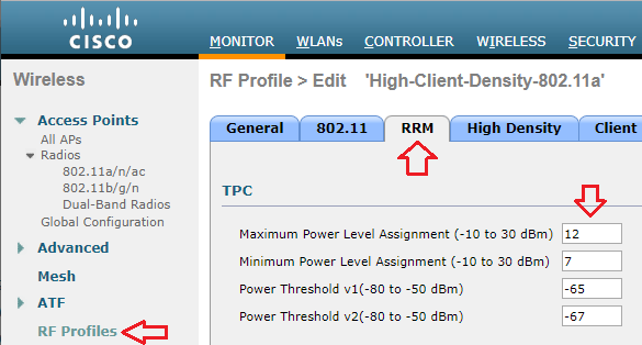
The TPC parameters can be configured under the RRM tab of our RF profile. We can then amend the following configuration parameters:
- Maximum Power Level Assignment.
- Minimum Power Level Assignment.
- Power Threshold v1.
- Power Threshold v2.
404 Not found

- Networking 101
Cisco Wireless Transmit Power Control

Power substation outside a VERY large data center in Atlanta,GA.
I’m going to start out by telling you something you probably already know. Every vendor has their own way of doing things. Sometimes it makes perfect sense, and other times you end up scratching your head wondering why that particular vendor implemented this feature or product. Since I have been spending a lot more time on wireless these days, I came across an issue that forced me to reconsider how transmit power control(TPC) actually works in a Cisco wireless deployment. I thought I would impart some of this information to you, dear reader, in the hopes that it may help you. If you spend a lot of time inside Cisco wireless LAN controllers, this may not be anything new to you.
The Need For TPC
If you have been around wireless long enough, you have probably dealt with wireless installs where all of the access points(AP) were functioning autonomously. While this isn’t a big deal in smaller environments, consider how much design work goes into a network with autonomous access points that number into the hundreds. It isn’t as simple as just deciding on channels and spinning all the access points up. You also have to consider the power levels of the respective access points. Failure to do so can result in the image below where the AP is clearly heard by the client device, but the AP cannot hear the client since it is transmitting at a higher power level than the client can match.
Now consider the use of a wireless LAN controller to manage all of those APs. In addition to things like dynamic channel assignment, you can also have it adjust the transmit power levels of the APs. This can come in handy when you have an AP fail and need the other APs to increase their transmit power to fill the gap that exists since that failed AP is no longer servicing clients. I should point out that proper design of a wireless network with respect to the client transmit power capabilities should NEVER be overlooked. You ALWAYS want to be aware of what power levels your clients can transmit at. It helps to reduce the problem in the image above.
There’s also the problem that can arise when too many APs can hear each other. It isn’t just about the clients. Wireless systems which adhere to the IEEE 802.11 standard are a half duplex medium. Only one device can talk at a time on a given channel. Either a client or the AP will talk, but not both at once. If an AP can hear another AP on the same channel at a usable signal, the airtime must be shared between those APs. Depending on the number of SSID’s in use, this can dramatically reduce the amount of airtime available for an AP to service a client. You can see some actual numbers with regard to SSIDs and APs in this blog post by Andrew von Nagy .
As you can see from two quick examples, there is a need to control the power level in which an AP will transmit. On controller based wireless networks(and even on the newer controller-less solutions), this is done automatically. I wouldn’t advise you turn that off unless you really know what you are doing and you have the time to plan it all out beforehand.
The Cisco Approach
On wireless LAN controllers, TPC is a function of Radio Resource Management(RRM). The specifics can be found here . I’ll spare you the read and give you the high points.
- The TPC algorithm is only concerned with reducing power levels. Increases in power levels are covered by Coverage Hole Detection and Correction algorithm.
- TPC runs in 10 minute intervals.
- A minimum of 4 APs are required for TPC to work.
It is the last point that I want to focus on, because the first two are pretty self explanatory. The reasoning behind the 4 AP minimum for TPC is as follows:
“For TPC to work ( or to even have a need for TPC ) 4 APS must be in proximity of each other. Why? Because on 2.4 GHz you only have three channels that do not overlap… Once you have a fourth AP you need to potentially adjust power down to avoid co channel interference. With 3 APS full power will not cause this issue.”
Those are not my words. They came from someone within Cisco that is focused on wireless. Since that person didn’t know I would publish that, I will not name said person. The explanation though, makes sense.
***Update – It appears that the Cisco documentation regarding TPC is a bit murky. Jeff Rensink pointed out in the comments below that TPC will also increase power levels. Although CHD will increase based on client information, I didn’t use any clients in my testing, as Jeff rightly assumed. The power increases I saw once I started removing AP’s from the WLC could not have been attributed to CHD adjustments. Read his comment below as he makes some very valid points. The NDP reference and accompanying link in his comment is fairly interesting.
Let’s see it in action to validate what Cisco’s documentation says.
TPC Testing
I happen to have a Cisco WLC 2504 handy with 4 APs. I set it up in my home office and only maintained about 10 feet separation from the APs. Ideally, I would test it with the APs a lot farther apart, but I did put some barriers around the APs to give some extra attenuation to the signal. I also only did testing on the 5GHz band. I disabled all of the 2.4GHz radios because I don’t need to give any of my neighbors a reason to hate me. Blasting 5GHz is less disruptive to their home wireless networks than 2.4GHz is due to the signals traveling farther / less attenuation of 2.4GHz vs 5GHz signals /antenna aperture. 🙂
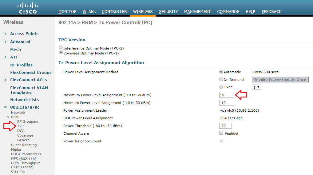
Here you can see the available settings for TPC in the WLC GUI. This particular controller is running 7.6 code, so your version may vary.
- You can either set TPC to run automatically, on demand, or at a fixed power rate on all APs. TPC is band specific, so if you want different settings for 2.4GHz and 5GHz respectively, you can have that.
- Maximum and minimum settings for transmit power are available. The defaults are 30dBm for maximum power and -10dBm for minimum power.
- The power threshold is the minimum level at which you need to hear the third AP for the TPC algorithm to run. The default is -70dBm. You can set it higher or lower depending on your needs. High density environments might require a level stronger than -70dBm, with -50dBm being the strongest level supported. If you don’t necessarily need to run things like voice, you might be able to get away with a weaker threshold, but you cannot go beyond -80dBm.
A Quick Sidebar on Maximum Transmit Power in 5GHz
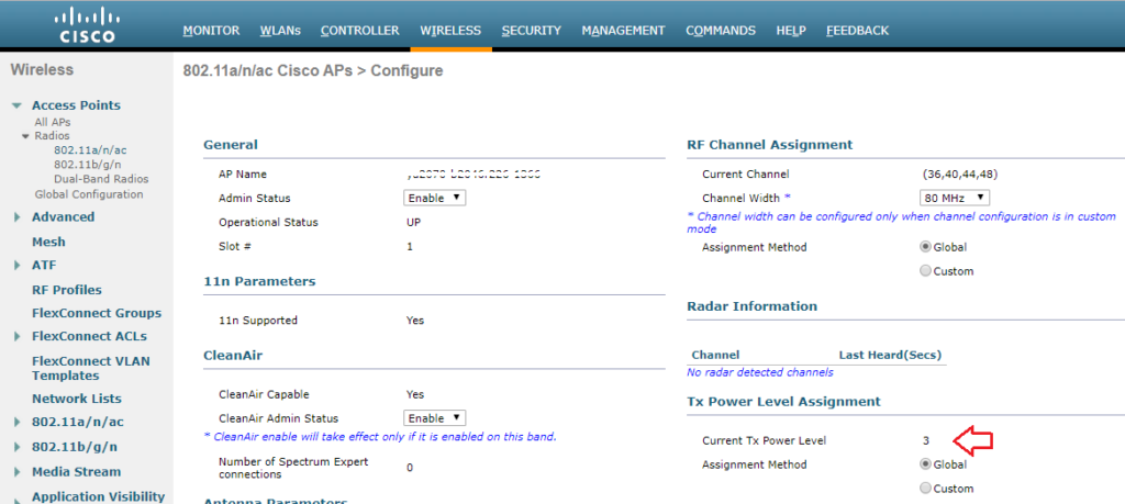
I set up the WLC with 3 APs active on 5GHz only. You can see that the power levels on the 3 APs are set to 1 in the image further down, which is maximum power according to Cisco. While it seems odd that max power would be a 1 and not some higher number, consider the fact that there are multiple maximum transmit power levels depending on which UNII band you are using in 5GHz. As a general reference, 20dBm would be 100mW and 14dBm would be 25mW. You could get 200mW(23dBm) of power using a UNII-3 channel vs UNII-1, which is maxed out 32mW(15dBm). That is a HUGE difference.
- 1 – 15dBm
- 2 – 12dBm
- 3 – 9dBm
- 4 – 6dBm
- 5 – 3dBm
- 1 – 17dBm
- 2 – 14dBm
- 3 – 11dBm
- 4 – 8dBm
- 5 – 5dBm
- 6 – 2dBm
- 1 – 23dBm
- 2 – 20dBm
- 3 – 17dBm
- 4 – 14dBm
- 5 – 11dBm
- 6 – 8dBm
- 7 – 5dBm
To see the supported power levels in terms of dBm on 5GHz, you can run the following command on the CLI of the WLC: show ap config 802.11a <ap name> The output will look something like this after you go through a handful of screens showing other stuff:
***Update – Brian Long wrote a blog post on this very thing! You can read it here .
Back To The Testing…
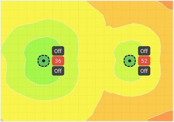
You can see in the image below that with 3 APs active, they are all running at power level 1, which is the default when the radios come online.
So let’s see what happens when I add the fourth AP. If our understanding of TPC is correct, we should see the power levels come down since the APs are so close to each other and will have a signal strength of well above -70dBm between each other.
Note – Power level decreases happen in single increments only, every time the TPC algorithm runs(every 10 minutes). To put it another way, it downgrades by 3dB max each cycle. Sam Clements pointed out to me via Twitter that when power levels increase, it can happen much more rapidly since the Coverage Hole Detection(CHD) and Correction algorithm is responsible for power increases.
If you want to see this work on the CLI in real time, you can issue the following command: debug airewave-director power enable
After I had waited for over half an hour, I decided to power off one more AP. When I brought it back online, I saw all 3 of the APs slowly go back to a power level of 1. Here’s the first change I saw in the 3 remaining APs:
It’s All In The Details
For wireless surveys, my company uses the Ekahau Site Survey product. It is a really neat survey tool and we use it for on site assessments as well as predictive surveys. When you define the requirements of the project, you can choose from a bunch of different vendor specific scenarios, or general wireless scenarios. I can apply those requirements to a predictive survey, or an on site survey where I am trying to determine if the existing coverage/capacity is good enough for the business needs.
Here’s a screen shot of the default requirements for the “Cisco Voice” scenario found in version 7.6.4 of Ekahau’s Site Survey program:
Closing Thoughts
Understanding how the TPC function works is pretty important when designing Cisco wireless networks. Failure to consider what all is involved in regards to transmit power on your APs could(not WILL, but COULD) lead to problems in the wireless network’s operation. However, if you want to manually set transmit power, that’s an option as well. Opinions differ on running RRM. I’m not sure there is a right or wrong answer. It depends. 🙂 I will say that I almost never see Cisco wireless implementations where RRM is not being used.
I don’t want to end this post without mentioning that some networks may be perfectly fine running APs at max power, especially on the 5GHz side. Your coverage may be enough to where there is minimal channel overlap(easily achievable in 5GHz with 20MHz channels and the use of all 3 UNII bands), and each AP can hear one or two neighboring APs at a decent level due to good cell overlap. You just might not have enough APs to trigger the TPC algorithm to run. That doesn’t mean “you are doing it wrong”. If it works for the business and all your users are fine, who am I to tell you that you need to “fix” it.
Hopefully this was beneficial to you if you needed a clearer understanding of how Cisco’s TPC function works. If you already have a good understanding of TPC and managed to read this far, feel free to shame humiliate correct me in the comments.
11 Responses to Cisco Wireless Transmit Power Control
Nice write up of the TPC process with actual testing. I would just make one correction.
The normal TPC algorithm should also raise power levels in addition to lowering them. This is evidenced in your testing as the powers raise up on the TCP interval when you took APs away. This is needed so that if an AP fails in real life, the surrounding APs can dynamically increase their power levels. The document that you linked actually says this. Although it also says that TCP is only used to decrease power (as you noted in your article). So it’s contradicting itself.
With coverage hole detection, the APs increase power in response to clients being connected at a low signal level. I haven’t seen any mention of CHD working to raise power in the absence of clients. So I don’t believe it has the capability to do so. Thus, if it were true that CHD was the only means to raise AP power, AP power would never raise without associated clients. I’ guessing in your tests, you didn’t have clients associated.
I don’t write this to pick on your article (it was very good). I just wanted to point out a common misconception that is unfortunately created by Cisco’s own documentation on the subject.
The other thing that bugs me about the RRM doc that you referenced is the inference that neighboring APs will be heard at lower RSSI levels as their power decreases. This is where they are talking about the TPC algorithm and how they use the power threshold value to determine if they should raise/lower power or not based on the 3rd loudest neighbor. The problem with that is that Neighbor Discovery Protocol (NDP) messages are always sent at the highest power/lowest data rate. So current AP power does not affect how loud a neighbor is heard, because TPC uses those NDP frames in its calculations. But part of the NDP information is the power level used to send the frame. So the TPC calculation can still do the math to figure out what power level is appropriate based on the threshold value.
For as important of a technology to understand as RRM is, Cisco definitely doesn’t make it easy to figure out. The article below helps fill in some information in regards to RRM. One of the nuggets is actually the reason why your power levels weren’t rising back up as quickly as you expected.
http://www.cisco.com/c/en/us/td/docs/wireless/controller/technotes/7-4/RRM_DG_74.html
Your comment is exactly the kind of additional information I was looking for in terms of corrections to my understanding of TPC, so I am grateful that you took the time to write it. There was a paragraph that I cut out of the blog post last night before publishing that I wish I would have left in after reading your comment. In that paragraph, I mentioned that when I powered off an AP, I still saw the TPC algorithm running via the “Last Power Level Assignment” field under the TPC page for 802.11a/n/ac. When I was proofreading, I pulled that paragraph because I thought it contradicted the RRM documentation stating that the TPC algorithm only cares about power decreases. It seemed like it would cause more confusion if I left it in.
After reading your comment, it makes a lot more sense now. I also appreciate the tidbit around NDP and how those messages actually work independent of the assigned power level to the AP.
Thanks again for the additional information. If I have some time, I will probably amend the post and reference your comment.
Great read Matthew. This is a keeper. 🙂
1. Regarding the comment from Cisco:
“For TPC to work (or to even have a need for TPC) 4 APs must be in proximity of each other. Why? Because on 2.4 GHz you only have three channels that do not overlap… Once you have a fourth AP you need to potentially adjust power down to avoid co-channel interference. With 3 APs full power will not cause this issue.”
DA > This is hideous…as you seemed to eluded to. The two major issues with this statement is that 1) it takes into consideration that you’re doing your testing inside a Faraday cage, and 2) there’s no such thing as adjacent channel interference. 🙁 I just had to get this off my chest. 🙂
While I can think of an advantage or two of using arbitrary numbers (e.g. 1-8) to represent power levels, the fact that they are so disparate across bands makes it non-intuitive for the Cisco novice. 1 should equal 1, 2 = 2, 3 = 3, etc…but no…of course not. 🙁 Confusion within the GUI is bad enough….but it’s much worse than that. Trying to assure maximum capacity, by uniformly mixing UNII-1 and UNII-3 channels (especially when DFS isn’t supported by many of your client devices), wouldn’t you end up with large cells and mid-sized cells unless TPC kicks in?
3. Question
It just seems silly to disable TPC unless there’s a 4th Cisco AP present in the network. Jeff mentioned that NDP is used in TPC calculations. Is that to say that neighboring APs can be used as TPC’s required-and-mysterious “4th AP”?
Again, great article. Very helpful.
Regarding your point number 1, I think they assume that anyone operating a wireless network will ONLY use 1, 6, and 11 inside the US. Of course, you and I both know that there are MANY networks run by people who just don’t seem to care about that.
As for point 2, it is fairly confusing when considering power levels at 5GHz. I would rather just have the scale start at 1 using the lowest level(-1dBm or 2dBm), and then go all the way up to whatever number on that scale represents 23dBm. You would still need to know what UNII band your 5GHz radio was on to know if you were at max power, but if I knew that power level 4 was always represented by 14dBm, I would know the radio was at 25mW. On the other hand, I can always look at power levels inside a Cisco WLC and know right away who is at max power, even though I still need to know what UNII band the radio is on.
To your point 3, my understanding of TPC is that it won’t even kick in until a 4th AP is heard. Although the AP’s are sending NDP messages to each other no matter what(I am going to verify this right now.), those messages are also used for other things like CleanAir and Rogue Detection according to the document that Jeff mentioned in his comment.
I just verified that NDP messages are still being sent every 60 seconds with just a single AP active on the WLC.
Awesome post and will be a great reference to customers we work with in Hospitals!
The fact that a ‘1’ is not a ‘1’ is definitely a challenge and can have a big effect on designs. Here is a reference ( http://blong1wifiblog.blogspot.com/2015/01/cisco-wireless-access-point-5ghz.html ) to output powers and the corresponding Cisco Power level for the 1131, 1242, 1142, 2602 and 3702 Cisco Access Points.
It was a hospital implementation that inspired this post. 🙂
Thanks for the link to the writeup you did. I will mention it when I update this post based on the comments received so far. TPC is definitely something that appears rather simple if you look at the settings within the WLC, but there is so much more to it. Even when I thought I understood it after testing, it turns out I really didn’t! Not sure I still do.
Great post, Matthew! On ESS and predictives for Cisco Voice, does it make sense to you to change the ESS defaults from 2 APs heard to min of 3 (plus dBm to -70, as you also suggest)? I am on conversation for tshoot of a poorly designed voice WLAN right now and if I have to go back out to do a predictive, I am just wondering if changing the defaults makes the best sense for a proper design. Thoughts?
Keep in mind that ESS is built with clients in mind. It isn’t necessarily concerned with AP to AP communication with respect to power levels. It does a great job of showing channel overlap, number of AP’s heard, etc. Without an understanding of how TPC works, you can layout AP’s to provide adequate coverage and capacity, but completely neglect how the AP’s will behave towards each other. By changing the defaults from 2 AP’s to 3 with a minimum signal level of -70dBm, you can ensure(as much as a predictive survey can) that your AP’s will see enough of each other to have the TPC algorithm run and let power levels adjust to something other than the maximum.
The “Network Issues” display in ESS will show areas in yellow that don’t meet this 3AP@-70dBm, or whatever value you set. You don’t need to try and get rid of all the yellow across the entire floor or area. You just need to get rid of it around the AP’s themselves. You will also have to ensure that the standard client coverage requirements(-67dBm for Cisco voice) are met, but with the amount of AP’s you will need to get TPC working, that shouldn’t be a problem. The alternative is to have all your AP’s running at max power since TPC didn’t have the right amount of AP’s at the right signal level to adjust power levels. While AP’s running at max power isn’t necessarily a bad thing, it will cause problems if you have an AP fail and none of the neighboring AP’s can increase power to offset the signal coverage gap from the failed AP. Additionally, with varying power levels across the UNII bands on 5GHz, max power could be anywhere from 25mW to 200mW. That could cause some big issues with voice deployments as you’ll run into the issue where the phone can hear the AP, but the AP can’t hear the phone.
My thoughts
I haven’t deployed a Cisco WLAN system (yet), but other vendors have the same or similar algorithm for that. But I haven’t used it once in my designs. Now I’m always open to rethink my designs, but relying on TPC (or similar) to cover holes if an AP fails or to reduce CCI just doesn’t seem quite right to me.
To cover holes upon an AP failure can be somewhat designed for with some proper cell overlap, however I would do that only in the 5GHz.
And CCI is not a factor of APs only, client devices are STAs too and they will equally effect other APs on the same channel. Plus lowering pwr for them completely obliterates your RSSI/SNR design. And lowering pwr also changes your MCS rates.
And just to compare, if a critical life-saving hospital component is low on battery and someone needs it immediately, those doctors won’t say: “Now, just try and hold on for a second while we charge this baby up. It really shouldn’t take long.” No, they’ll get a new one ASAP having it ready on standby. So the same must apply to APs if it’s a mission critical component.
So using something like TPC just doesn’t seem prudent to me. I’d rather use a fixed power value and design around that, but then again, I’m always open for new ideas.
I would be curious how you design around failure of an AP. Do your designs have enough cell overlap to where a failed AP would be covered by other AP’s nearby? Additionally, how do you deal with persistent interference and orchestrate cascading channel changes to compensate for that? This wouldn’t necessarily be an issue on 5GHz if you are using multiple UNII bands and 20MHz channels, but it would definitely be an issue on the 2.4GHz side.
I suppose it all depends on how responsive a company can be to failures in the network. TPC, or any other vendor implementation for that matter, can dynamically change based on the RF conditions. If everything is manually set, it requires manual intervention. I am not saying that there isn’t a use case for manually setting transmit power and channel assignments. I just think the majority of people supporting wireless networks out there would prefer to automate as much of the process as possible. Thanks for your viewpoint!
Comments are closed.
- December 2018
- January 2017
- October 2015
- February 2015
- January 2015
- October 2014
- September 2014
- August 2014
- February 2014
- November 2013
- October 2013
- January 2013
- December 2012
- September 2012
- August 2012
- February 2012
- January 2012
- December 2011
- November 2011
- September 2011
- August 2011
- February 2011
- January 2011
- December 2010
- November 2010
- October 2010
- September 2010
- August 2010
Recent Comments
- Matthew Norwood on Aerohive’s Private Pre-Shared Key Technology
- Lee Badman on Aerohive’s Private Pre-Shared Key Technology
- Matthew Norwood on Does Aerohive Scale?
- Chris Carlton on Does Aerohive Scale?
- Marc on From Multi-Vendor To Single-Vendor
Wait, but Wi-Fi?
Transmit Power Control Considerations
Proper configuration of Transmit Power Control (TPC) settings can help to ensure that your Access Point (AP) does not speak too loudly. If your AP is transmitting at 18dBm and an associated client station (STA) is at the cell edge and only capable of transmitting at 15dBm, your client will be able to hear the AP transmission, but the AP won’t be able to hear the client which leads to retransmissions and thus reduced performance.
Wireless network design is ultimately dependent upon the clients it is to support, so we will want to have an idea of what our intended clients are capable of. As an example, one of my customer’s clients is an HP EliteBook 8470p laptop workstation which has a Broadcom BCM943228HM4L Wi-Fi adapter. According to the product specification web page for this particular model, I was able to find that it is capable of transmitting at around 15dBm. If this is my customer’s least capable device, I would not want my AP to transmit louder than 15dBm either.
My customer is using a Cisco 3504 Wireless Controller running AireOS version 8.8. I am able to globally configure the Maximum Power Level Assignment to 15dBm.
If the same controller were managing multiple locations with different requirements, I can also set a Maximum Power Level Assignment for different RF Profiles.
Though the maximum power level is configured in dBm, Cisco uses a series of numbers to represent levels of power. Phil Morgan of NC-Expert wrote an article titled WLC and AP Power settings in which he discusses Cisco power levels in further detail. In his article, he discusses how we can determine what the power levels represent as they vary by AP model, band (2.4 vs 5GHz), and even channel groupings (i.e. U-NII 1, 2, 2e, 3).
I also stumbled upon an excellent post by Maxim Risman in the Cisco Community titled Cisco Access point 2802i Tx Power Chart where he demonstrates the use of another very helpful command which summarizes the power levels of all APs: show advanced 802.11a txpower
Note that the range for the power levels actually does not change, but rather TPC is limiting the highest level that can be used.
The current power level setting can also be found in the web GUI by navigating to Wireless > Access Points > Radios. There, you can see the power level for all of your APs in a column, or you can dive in to the configuration of a radio.
When performing predictive site surveys with Ekahau Pro site survey software, we have the ability to adjust the transmit power with which to generate our expected heat maps.
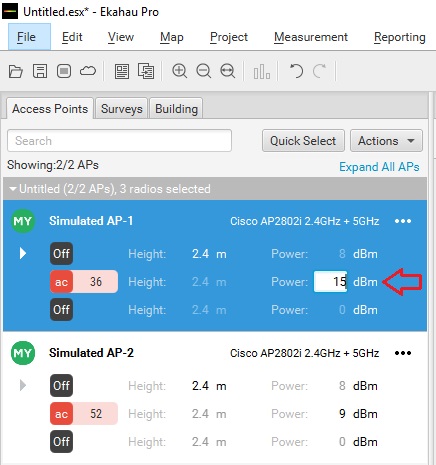
We can get an idea of how this difference may affect our design in the real world.
If you are interested in getting deeper into Cisco’s TPC implementation, you may want to check out a whitepaper they have published titled Transmit Power Control (TPC) Algorithm .

Published by Stephen
View all posts by Stephen
The Cisco Learning Network

adrianch12 asked a question.
I´m installing new APs 3802 with WLC 5508, and I discovered that in this model i can´t move the TX power level assignment in the 2.4Ghz (802.11b/g/n ) radio. Somebody know if it is possible to move this configuration?. In the AP model 3702 or 3602 it is possible.
- Enterprise Certifications Community
- Enterprise Wireless Certifications Community
I solved this problem, i have to change to manual, and then clic apply, with this the funtion to move the power level is activated
Phil Morgan
Yes. You have to take it off RRM control, to manually change the power level or channel.
Be careful though, the power levels are not linear, and depend on region and frequency.
I did write a blog entry on this that you may find useful:
AP Power settings made easy, and troubleshooting wireless networks
Related Questions
Trending articles.
- Cisco Packet Tracer: Software de Simulación para Redes
- 200-301 CCNA Study Materials
- Continuing Education Credits Automation
- Packet Tracer Labs
- CCIE/CCDE: Book your Lab/Practical Exam
If you encounter a technical issue on the site, please open a support case .
Communities: Chinese | Japanese | Korean
Cisco.com © Copyright 2024 Cisco, Inc. All Rights Reserved. Privacy Statement Terms & Conditions Cookie Policy Trademarks
- Skip to content
- Skip to search
- Skip to footer
Cisco Wireless LAN Controller (WLC) Configuration Best Practices
Available languages, download options.
- PDF (1.3 MB) View with Adobe Reader on a variety of devices
Bias-Free Language
The documentation set for this product strives to use bias-free language. For the purposes of this documentation set, bias-free is defined as language that does not imply discrimination based on age, disability, gender, racial identity, ethnic identity, sexual orientation, socioeconomic status, and intersectionality. Exceptions may be present in the documentation due to language that is hardcoded in the user interfaces of the product software, language used based on RFP documentation, or language that is used by a referenced third-party product. Learn more about how Cisco is using Inclusive Language.
Introduction
Mobility has rapidly changed the expectation of wireless network resources and the way users perceive it. Wireless has become the preferred option for users to access the network, and in many cases the only practical one. This document offers short configuration tips that cover common best practices in a typical Wireless LAN Controller (WLC) infrastructure. The objective of this document is to provide important notes that you can apply on most wireless network implementations.
Prerequisites
Requirements.
Cisco recommends that you have knowledge of these topics:
Knowledge on how to configure the Wireless LAN Controller (WLC) and Lightweight Access point (LAP) for basic operation
Basic knowledge of Control And Provisioning of Wireless Access points (CAPWAP) protocol and wireless security methods
Components Used
The information in this document was based on these software and hardware versions:
Cisco series WLC that runs software release 8.2 and above
Cisco 802.11n and 11ac series APs
General Settings
Configuration changes.
It is mandatory to reload the controllers after you change these configuration settings:
Management address
SNMP configuration
HTTPS encryption settings
LAG mode (enable/disable)
Configuration File Management
- Do not use a file from one controller type into another, for example a 2500 into a 5520. Some fields, especially password data, may be lost. If you need to use files across controller models, use a file conversion tool https://cway.cisco.com/tools/WirelessConfigConverter/
- Do not do configuration changes when a configuration upload is in progress, to avoid any possible data corruption.
- As a precaution, always do a configuration backup before a code upgrade.
Configuration files may contain sensitive data. If you want to ensure password confidentiality, use the transfer upload encrypted file feature when doing configuration backups from the controller.
Core Dump Export
In case of a controller crash, it is possible to enable automated upload of core dump for analysis to a FTP server, this file can be provided to TAC for further analysis. By default this feature is enabled
How to configure :
To validate the configuration :
Related Documentation:
https://supportforums.cisco.com/t5/wireless-mobility-documents/how-to-find-amp-retrieve-wlc-s-crash-coredump-from-its-s-flash/ta-p/3145554
Support Bundle
In recent releases (8.0.150.0, 8.2.160.0 and higher versions), the controller now supports a single file upload option to easily collect the most important support data in a simplified way. This will provide a bundle covering crash information, core files, configuration, RRM logs, and RF state data. It is advisable to always include this file when opening a TAC case, to have a good starting data set.
How to Upload (proceed with file upload mode as needed)
Related documentation: https://www.cisco.com/c/en/us/td/docs/wireless/controller/8-6/config-guide/b_cg86/managing_configuration.html#diagnostic-support-bundle
Fast Restart
It is recommended to use restart instead of reset system for the following scenarios to reduce network and service downtime and provide better serviceability:
- LAG Mode Change
- Mobility Mode Change
- Web-authentication cert installation
- Clear Configuration
The Fast Restart feature is supported on Cisco WLC 7510, 8510, 5520, 8540, and vWLC from release 8.1.
To restart the controller:
mDNS Gateway
Bonjour, an Apple's service discovery protocol, locates devices such as printers, other computers, and the services that those devices offer on a local network using multicast Domain Name System (mDNS) service records. Bonjour is a link local protocol that does not cross L3 boundaries. With Bonjour gateway, Apple devices can discover Bonjour services across a layer 3 boundary (across different VLANs) without additional configuration on the end user device(s).
Using a mDNS gateway can reduce significantly the amount of multicast traffic flooded across the wireless network, as the responses are handled directly as unicast towards the device sending them, optimizing the use of RF time.
Also, this removes Bonjour from the CAPWAP multicast traffic requirements, reducing overall network load.
To enable/disable global mDNS snooping:
To enable/disable mDNS support for a WLAN:
Enable Fast SSID Changing
When fast SSID changing is enabled, the controller allows clients to move faster between SSIDs, changing the client context between WLANs, instead of forcing a client delete and a wait time. From a security point of view, it is preferable the disable option, as there is full confirmation of all client state is deleted before it is allowed on another WLAN, that may have different security policies.
The enable option is advisable when Apple IOS clients are present, as these devices do not work properly with the "delete on WLAN change" behavior, and they may have the currently associated AP in a blocked list.
To enable fast SSID change:
Enable High Availability Client/AP SSO
High Availability (HA) with Client SSO is a feature supported from controller version 7.4 and higher. This allows a pair of controllers to act as a single network entity, working in an active/standby scenario, while preserving AP and client states, and ensuring that devices will not have to authenticate in case of a failure on the current active controller.
Whenever allowed by the controller hardware type in use, it is advisable to take advantage of the HA SSO feature, to reduce any possible downtime in case of failure.
High Availability (SSO) Deployment Guide
N+1 High Availability Deployment Guide
Load Balancing Window
If load balancing is required on the WLAN, ensure that the controller has a global windows set to 5 clients or higher, to prevent association errors
Aggregated Probe Response Optimizations
For large high density deployments, it is advisable to modify the default aggregate probe interval sent by access points. By default, the APs will update every 500ms about the probes sent by clients, this information is used by load balancing, band select, location and 802.11k features.
If there is a large number of clients and access points, it is advisable to modify the update interval, to prevent control plane performance issues in the WLC.
That would set it to 50 aggregated probe responses every 64 seconds.
Access Points
Configure predictive join.
When configuring access points, always set the primary/secondary controller names, to control the AP selection during the CAPWAP join process. This can prevent "salt & pepper" scenarios that affect roaming time, make troubleshooting simpler and have a more predictive network operation.
To configure:
Set AP syslog destination
Access points will generate syslog about important events for troubleshooting and serviceability. By default, they will use a local broadcast destination (255.255.255.255), to ensure that even when the AP is out of the box, it is possible to obtain some information about possible problems by doing a local capture.
For performance, security and ease of troubleshooting, it is recommended to set a unicast destination, and store the AP logs for later analysis in case of problems:
To configure for all access points that will join the controller:
Rogue Location Detection Protocol (RLDP)
If the RLDP feature is needed, use it only with monitor mode APs, to prevent performance and service impact to the wireless network.
The following sections list out the best practices for network related features.
AP recommendations
Use portfast on ap switch ports.
For APs in local mode, or Flexconnect mode doing only central switched WLANs, configure the switch port with PortFast. To configure PortFast, set the port to be connected as a "host" port (switchport host command) or directly with the portfast command. This allows a faster join process for an AP. There is no risk of loops, as the local mode APs never bridges traffic directly between VLANs.
The port can be set directly on access mode. Enable port fast, and remove any group membership with the command "switchport host", supported on most switch platforms
Configuring Spanning Tree PortFast
Using PortFast and Other Commands to Fix Workstation Startup Connectivity Delays
Prune VLANs for Flexconnect mode AP Switch Ports
For APs in Flexconnect mode, when using locally switched WLANs mapped to different VLANs (AP switch port is on trunk mode), prune or limit the VLANs present on the port to match the AP configured VLANs.
Global Traffic Forwarding Configurations
Enable TCP MSS across all APs
To optimize the TCP client traffic encapsulation in CAPWAP, it is recommended to always enable TCP MSS feature, as it can reduce the overall amount of CAPWAP fragmentation, improving overall wireless network performance. The MSS value should be adjusted depending of the traffic type and MTU of the WLC-AP path. In general, a 1300 bytes value is a good average, although it can be further optimized depending on your setup.
Controller recommendations
Prune vlans.
To avoid unnecessary work of the controller data plane, it is advisable to always prune unused VLANs from the trunk ports arriving to the WLC, and only leave those that are configured as management and dynamic interfaces.
DHCP Proxy Mode
Per design, most of the CPU initiated traffic is sent from the management address of the controller, for example, SNMP traps, RADIUS authentication requests, multicast forwarding, and so on.
The default exception to this rule is DHCP related traffic. By default, the WLC is in DHCP proxy mode, and all DHCP traffic related to a client, is sent from the interface corresponding to the WLAN where client is associated, with the WLC as relay agent and source IP. If the WLC is in DHCP bridge mode, the traffic is transparently bridged to the corresponding VLAN.
- From best practices point of view, using DHCP bridge or proxy modes is mostly equivalent and it depends on the specific scenario being deployed. In general, using proxy mode is preferable for security reasons, as it hides the DHCP server IP from clients.
- Ensure that DHCP mode matches across controllers in the same mobility group.
It is possible to configure DHCP proxy mode per interface, or globally. If this is changed, ensure that the interface mode configuration matches all controllers in same WLAN mobility group.
Configuring DHCP Proxy
Disable Internal DHCP
The controller has the ability to provide an internal DHCP server. This feature is not scalable and is normally used for a simple demonstration or proof-of-concept or for very small networks (low client count), for example in a lab environment. The best practice is not to use this feature in an enterprise production network.
The show interface detailed management command is used to find if an internal DHCP server is configured. The primary DHCP server address is the same as the management IP address. See the following example:
Change the internal DHCP server (management IP address) to a production DHCP server:
Same DHCP servers per Interface across WLCs
When deploying multiple WLCs to handle a WLAN across a mobility group, ensure that the interfaces on each WLC have the same DHCP servers configured, to prevent address negotiation errors during client roaming.
DHCP Timeout
WLC has a timeout for each client state (authentication, DHCP address negotiation, webauth pending, etc.). It is possible to change the default time allowed for a client to complete a successful address negotiation. This could be useful on some topology scenarios, for example, where the same SSID is served by 2 different controller groups that do not share a mobility relationship, and you want to force clients to be deleted and restart DHCP negotiation after an inter-controller roam.
By default, the timer is 120 seconds, and can be verified with:
Do not use a very short value, as it may lead to client disconnection on some scenarios. For example, on multi-controller mobility group, the initial client association may take up to 3 seconds to allow for L3 roaming negotiation. If the DHCP timer is set too low, it could cause unnecessary client disconnections, depending on the client DHCP discover request timers. The value should not be set lower than 10 seconds.
Configuring a DHCP Timeout
IP addressing
Do not leave an interface with a 0.0.0.0 address. It might negatively affect DHCP handling in the controller.
Do not use addresses starting with 127.x.x.x as it can break Web Authentication feature.
Virtual Gateway IP
It is recommended to configure a non-routable IP address for the virtual interface, ideally not overlapping with the network infrastructure addresses. Use one of the options proposed on RFC5737, for example, 192.0.2.0/24, 198.51.100.0/24, and 203.0.113.0/24 networks.
To change the address:
- When using Link aggregation (LAG) make sure all ports of the controller have the same Layer 2 configuration on the switch side. For example, avoid filtering some VLANs in one port, and not the others.
The controller relies on the switch for the load balancing decisions on traffic that come from the network, with “source-destination IP” as the typically recommended option. It is important to select a correct balancing configuration on the switch side, as some variations may have an impact on controller performance or cause packet drops on some scenarios, especially for 5520/8540/WISM2 models due to their hardware architecture, where traffic from different ports is split across different data planes internally.
To change the switch configuration (IOS):
- With the Cisco IOS Software Release 12.2(33)SXH6 and above, there is an option for PFC3C mode chassis to exclude VLAN in the Load-distribution. Use the port-channel load-balance src-dst-ip exclude vlan command to implement this feature. This feature ensures that traffic that belongs to an LAP enters on the same port.
- For LAG scenarios, using VSS, stacked switch (3750/2960), or Nexus VPC, should work as long as the fragments of an IP packet are sent to the same port. The idea is if you go to multiple switches, the ports must belong to the same L2 “entity” with regard to load balancing decisions.
Non LAG topology
To connect the WLC to more than one switch, you must create an AP manager for each physical port and disable LAG. This provides redundancy and scalability. It is not supported to have a WLC with a port up, without a corresponding AP manager interface.
Do not create a backup port for an AP-manager interface. This was possible in older software versions. The redundancy is provided by the multiple AP-manager interfaces as mentioned earlier in this document.
Management Interface Vlan Tag
Cisco recommends to use VLAN tagging for the management interface of the WLC, as this is required for High Availability deployments. For untagged interface, the packet sent to and from the management interface assumes the Native VLAN of the trunk port to which the WLC is connected. However, if you want the management interface to be on a different VLAN, tag it to the appropriate VLAN with the command:
Ensure that the corresponding VLAN is allowed on the switchport and tagged by the trunk (non-native VLAN).
Preventing Traffic Leaksfor Guest or AAA override scenarios
A "Black Hole" dynamic interface is a configuration scenario, where the dynamic interface VLAN configured on the controller, is not forwarded by the switch, or lacks any default gateway. Any client assigned to this interface, can't pass traffic or reach any network destination, with the goal of preventing a human configuration error, and reducing the possibility of traffic leaks.
This scenario is targeted for:
- Guest access or mobility auto-anchor: Configure a black hole interface on the foreign, to ensure that there is no traffic leak at foreign level, and that the only connectivity possible is through the anchor assigned interface
- AAA override: This ensures that all clients must get an assigned interface from the RADIUS server, or they can’t reach any network destination
WLAN General Recommendations
Use broadcast ssid.
WLANs can operate "hiding" the SSID name, and only answer when a probe request has the explicit SSID included (client knows the name). By default the SSID is included in the beacons, and APs will reply to null probe requests, providing the SSID name information, even if clients are not pre-configured with it.
Hiding the SSID does not provide additional security, as it is always possible to obtain the SSID name by doing simple attacks, and it has secondary side effects, such as slower association for some client types (for example Apple IOS), or some clients can't work reliably at all in this mode. The only benefit is that it would prevent random association requests from devices trying to connect to it.
It is recommended to enable Broadcast SSID option to have best interoperability.
Voice–CCKM Timestamp Validation
Change CCKM validation to 5 seconds to avoid picocells or roaming issues when using Cisco clients (7925/7921/WGB):
RADIUS source interface
As mentioned previously, WLC will source most of the traffic from its management interface, with the exception of DHCP. RADIUS is an special case, where it is possible to do a per WLAN setting, to force traffic to be sourced from the default interface of the WLAN, instead of using the management interface.
This is useful on some topology scenarios, where the authentication server is local to the WLC, and the management is done by a separated administration entity (Managed service providers, some enterprise deployments)
- Enabling a per WLAN RADIUS source interface has implications when you configure firewall policies, or design the network topology. It is important to avoid configuring a dynamic interface in the same sub-network as a server, for example the RADIUS server, that is reachable from the controller, as it might cause asymmetric routing issues
- This feature may create design issues with Bring Your Own Device (BYOD) flow and Change of Authorization (CoA). Also it is not compatible with some AAA override scenarios
Related information:
Per-WLAN RADIUS Source
Interface Groups
The Interface Group or VLAN Select feature enables you to use a single WLAN that can support multiple VLANs corresponding to different DHCP pools dynamically for load balancing. Clients get assigned to one of the configured VLANs using a hash of their MAC address, so the assignment is preserved over time, unless there is an interface group configuration change.
The VLAN Select pool feature will monitor the DHCP server responses, and automatically stop using those VLANs that have clients that fail to obtain a DHCP address assignment.
To enable VLAN Select, perform the following steps:
- Create an interface group.
- Add interfaces to the interface group.
- Add the interface group to a WLAN.
To create an interface group:
To add interfaces to the interface group:
To add the interface group to a WLAN (CLI):
To change the DHCP pool exhaustion detection algorithm:
Multicast VLAN
If interface groups are in use, it is recommend to enable multicast VLAN to limit multicast on the air to a single copy on a predefined multicast VLAN.
Enable Multicast VLAN by entering this command:
Enable Local Client Profiling
Knowing the client type can be extremely useful for troubleshooting scenarios, assigning policies per device type, or optimizing the configuration to adapt to them. Local profiling adds an easy way to detect the client types connected to the controller, without any external server dependencies.
The controller will parse DHCP or HTTP requests from clients, against a known set of client type rules to make the best fit evaluation on the device type.
The information is available on the WLC GUI or through the CLI.
To enable local profiling on a WLAN:
To see the information on the CLI:
Application Visibility and Control (AVC)
Application Visibility and Control (AVC) classifies applications using Cisco's Deep Packet Inspection (DPI) techniques with Network-Based Application Recognition (NBAR) engine and provides application-level visibility and control into the Wi-Fi network. After recognizing the applications, the AVC feature allows you to either drop or mark the traffic.
Using AVC, the controller can detect more than 1000 applications. AVC enables you to perform real-time analysis and create policies to reduce network congestion, costly network link usage, and infrastructure upgrades.
AVC is supported on the following controller platforms: Cisco 2500/3500 series controllers, Cisco 5500 series controllers, Cisco Flex 7500 series controllers in central switching mode, Cisco 8500 series controllers, and Cisco WiSM2.
To enable AVC visibility on a WLAN (for baseline application utilization):
To show AVC statistics on a WLAN (show application utilization per WLAN):
A general use case is to mark/drop/rate-limit traffic, such as in the following example, to prioritize Microsoft Lync traffic for best user experience when making a Lync video/voice call.
To create the AVC profile:
To add one or more rules to the AVC profile (mark Lync Audio with DSCP 46, video with DSCP 34):
To apply the AVC profile to a WLAN:
Enable 802.11k for Optimal Roaming
The 802.11k standard allows clients to request neighbor reports containing information about known neighbor APs that are candidates for a service set transition. The use of the 802.11k neighbor list can limit the need for active and passive scanning.
A common problem that 802.11k helps solve is to deal with "sticky clients", which usually associate with a specific AP, and then holds onto that AP strongly even when there are significantly better options available from nearer APs.
To enable 802.11k neighbor list for a WLAN:
To enable dual-band 802.11k neighbor list for a WLAN:
It is recommended to enable 802.11k with dual-band reporting. With dual-band reporting enabled, the client receives a list of the best 2.4 and 5 GHz APs upon a directed request from the client. The client most likely looks at the top of the list for an AP on the same channel, and then on the same band as the client is currently operating. This logic reduces scan times and saves battery power. Remember that dual-band reporting should only be used if the clients associating to the WLAN are dual band capable.
To enable assisted roaming prediction list feature for a WLAN:
Sleeping Client feature and Idle timer
If using the Sleeping Client feature for web authentication, ensure that your idle timeout is lower than the session timeout, to prevent incorrect client deletion.
802.11v and Management Frame Protection (MFP)
When 802.11v feature is in use, it is recommended to disable the MFP infrastructure feature, as the combination can cause interoperability problems with some devices.
Flexconnect and Address Learning flag
For the FlexConnect local switching, central authentication deployments, for the scenarios of:
- Passive client with a static IP address, for example printer server, weight scales, camera, etc
- Multiple remote sites with overlapping local IP address range for clients
It is recommended to disable the Learn Client IP Address feature. This can be done in GUI from the WLAN settings, Advanced tab, or with command:
Multicast Recommendations
Multicast forwarding mode.
Use multicast forwarding mode for the best performance with less bandwidth utilization for multicast applications when the underlying switched infrastructure supports multicast. Networks with large IPV6 client counts, multicast Video Streaming and Bonjour without mDNS proxy, may benefit greatly with multicast mode.
If the APs are on different subnets than the one used on the WLC's management interface and AP Multicast Mode is enabled, your network infrastructure must provide multicast routing between the management interface subnet and all APs subnets, otherwise all multicast traffic will be lost.
To verify the multicast mode on the controller:
To configure multicast-multicast operations on the WLC command line:
More information about the selection of multicast addresses within the enterprise can be located here https://www.cisco.com/c/dam/en/us/support/docs/ip/ip-multicast/ipmlt_wp.pdf
Multicast Address for CAPWAP
The multicast address is used by the controller to forward traffic to Access Points (APs). Ensure that the multicast address does not match another address in use on your network by other protocols. For example, if you use 224.0.0.251, it breaks mDNS used by some third party applications.
Cisco recommends that the address be in the private range (239.0.0.0 – 239.255.255.255, which does not include 239.0.0.x and 239.128.0.x, as those ranges will cause L2 flood). Also, ensure that the multicast IP address is set to a different value on each WLC to avoid multicast packet duplication.
More information about the selection of multicast addresses within the enterprise can be located here: https://www.cisco.com/c/dam/en/us/support/docs/ip/ip-multicast/ipmlt_wp.pdf
IGMP and MLD Snooping
Using IGMP and MLD snooping may provide additional multicast forwarding optimization, as only APs with clients that have joined the respective multicast groups, will transmit the multicast traffic over the air, so this is a recommended setting to have in most scenarios.
Always check your client and multicast application behavior, as some implementations may not do IGMP group join, or may not refresh properly, causing the multicast streams to expire. It is possible to modify the IGMP timeout if needed, to adapt to client side or switch behaviors
Multicast/Broadcast Setup
The following sections address best practices for security.
AP Security Recommendations
Change default ap console user.
By default, Access Points have a default Cisco/Cisco username and password, with SSH and telnet disabled. It is advisable to configure a default password, to be applied as soon as they first join the controller:
802.1x Authentication for AP port
For increased security, configure 802.1X authentication between a lightweight access point (AP) and a Cisco switch. The AP acts as an 802.1X supplicant and is authenticated by the switch using EAP-FAST with anonymous PAC provisioning. This is configurable in the global authentication settings.
To configure the global authentication username and password for all APs, currently joined to the controller as well as any AP that will join the controller in the future:
To verify the configuration:
Configuring the Switch for Port Authentication
The following is a sample configuration to enable 802.1X authentication on a switch port:
HTTPS Recommendations
Enable secure web access.
For increased security, confirm that HTTPS is enabled and HTTP is disabled for management access (default settings).
To confirm management Web Access configuration:
To disable HTTP management access:
To enable secure web mode:
Enable High Encryption for Web Access
By default, WLC allows low security crypto options for HTTPS negotiation to ensure backward compatibility, which are no longer considered strong enough in several scenarios. For security reasons, it is advisable to force the controller to use only strong cyphers with the high encryption command. This may cause some interoperability issues if the client connecting to HTTPS only supports legacy or limited crypto options, so it is advisable to do testing for possible issues. This is not a problem for most modern browsers and operating systems.
To see the state:
To enable higher crypto options for HTTPS for management GUI:
To enable higher crypto options for HTTPS for webauth WLANS:
Ensure legacy crypto options are disabled for HTTPS
The Cisco Wireless LAN Controllers supports some older crypto option negotiation for HTTPS for compatibility reasons: SSLv2, SSLv3 support, and RC4 crypto preference. They are disabled by default, as they are affected by different protocol or cryptographic vulnerabilities, and only provided for backward compatibility.
The SSLv2 and RC4 options are deprecated on later releases, so it is no longer present.
These options are not needed on almost all scenarios, and only should be enabled on very specific corner cases for old HTTPS client connectivity to WLC management and webauth features.
To check if whenever they are enable (8.2 and older):
In 8.3 and higher:
To disable them:
Ensure CSRF protection is in place
Cross Site Request Forgery is a type of attacks where an unsuspected user is tricked to perform unwanted actions. Starting with 8.3, Cisco Wireless LAN Controllers have embedded CSRF protection across all the management web interface.
This is enabled by default, and there is no reason to disable it, unless required as workaround for some specific issue. It should have no impact when active.
How to check:
How to enable:
SSH Recommendations
Secure ssh/telnet.
Similar to secure web access, confirm that SSH is enabled and Telnet is disabled to the controller for better security.
To see the network summary:
To disable Telnet:
To enable SSH:
Secure SSH High Crypto
The Cisco Wireless LAN Controllers support higher crypto protocol negotiation for SSH connections. This is disabled by default, as older SSH clients may not support these cypher offerings. If your client is compatible, it is recommended to enable this option. Always test compatibility before implementing across a production network.
To check if it is enabled:
WLAN Security Recommendations
Enable 802.11r fast transition.
802.11r is the IEEE standard for fast roaming, where the initial authentication handshake with the target AP (that is, the next AP that the client intends to connect to) is done even before the client associates to the target AP. This is called Fast Transition (FT), and by default, fast transition is disabled in releases before 8.3. As of 8.3, a new capability called Adaptive FT is enabled by default, which is used for Apple IOS devices (see Apple recommendations section).
Using either FT or Adaptive FT can lower the total usage of the authentication services, as clients can do secure roaming without incurring full authentication on each AP change, so this has benefits both in roaming speed and overall reduced authentication load.
To enable 802.11r or Fast Transition (FT):
To configure FT authentication management using 802.1X:
To configure FT authentication management using PSK:
DHCP Required Option
To enhance security, Cisco recommends that all clients obtain their IP addresses from a DHCP server.
The DHCP Required option in WLAN settings allows you to force clients to do a DHCP address request/renew every time they associate to the WLAN before they are allowed to send or receive other traffic to the network. From a security standpoint, this allows for a more strict control of IP addresses in use, but this might also have an effect in the total time for roaming before traffic is allowed to pass again.
Additionally, this might affect some client implementations that do not do a DHCP renew until the lease time expires. This depends on the client types, for example, Cisco 7921 or 7925 phones might have voice problems while they roam if this option is enabled, as the controller does not allow voice or signaling traffic to pass until the DHCP phase is completed. Another example may include Android and some Linux distributions that only do DHCP renew on half the length of the lease time, but not on roaming. This may be a problem if the client entry expires.
Some third-party printer servers might also be affected. In general, it is a good idea not to use this option if the WLAN has non-Windows clients. This is because, stricter controls might induce connectivity issues, based on how the DHCP client side is implemented.
To verify the DHCP Required option in WLAN settings:
Disable Aironet IE
Aironet IE is a Cisco proprietary attribute used by Cisco devices for better connectivity and troubleshooting. It contains information, such as the access point name, load, and number of associated clients in the beacon and probe responses of the WLAN that are sent by the access point (AP). Cisco Client Extensions (CCX) clients use this information to choose the best AP with which to associate.
The CCX software is licensed to manufacturers and vendors of third-party client devices. The CCX code on these clients enables them to communicate wirelessly with Cisco APs and to support Cisco features that other client devices do not. The features are related to increased security, enhanced performance, fast roaming, and power management.
To disable Aironet IEs for a particular WLAN:
Client Exclusion
When a user fails to authenticate, the controller can exclude the client. The client cannot connect to the network until the exclusion timer expires or is manually overridden by the administrator. This feature can prevent authentication server problems due to high load, caused by intentional or inadvertent client security misconfiguration. It is advisable to always have a client exclusion configured on all WLANs.
Client Exclusion can act as a protective mechanism for the AAA servers, as it will stop authentication request floods that could be triggered by misconfigured clients.
Exclusion detects authentication attempts made by a single device. When the device exceeds a maximum number of failures, that MAC address is not allowed to associate any longer.
The Cisco WLC excludes clients when the following conditions are met:
- Excessive 802.11 Association Failures after five consecutive failures
- 802.1X Authentication Failures after three consecutive failures
- IP Theft or IP Reuse, if the IP address obtained by the client is already assigned to another device
- Excessive Web Authentication Failures after three consecutive failures
It is possible to configure how long a client remains excluded, and exclusion can be enabled or disabled at the controller or WLAN level.
To verify exclusion policy:
Related documentation:
Management Frame Protection
Peer-to-peer Blocking
Peer-to-peer blocking is a per WLAN setting, and each client inherits the peer-to-peer blocking setting of the WLAN to which it is associated. Peer-to-peer enables you to have more control over how traffic is directed. For example, you can choose to have traffic bridged locally within the controller, dropped by the controller, or forwarded to the upstream VLAN.
This setting can prevent a client attacking another client connected to the same WLAN, but it is important to keep in mind that using the drop option will prevent any application that can communicate directly between clients, for example chat or voice services.
WLAN Security
To verify the peer-to-peer blocking setting of the WLAN:
To configure a WLAN for peer-to-peer blocking:
Disable Local EAP
Local EAP is an authentication method that allows users and wireless clients to be authenticated locally on the controller instead of using a Radius server. Using local EAP in an enterprise production environment is not recommended for scalability reasons.
To check if a WLAN is configured to use local EAP:
To disable local authentication on a WLAN:
WPA2 + 802.1X WLAN
From security standpoint, it is advisable to configure WLANs with WPA2 with AES encryption, and 802.1x authentication. Other security policies like open, WEP, WPA/TKIP, etc, should be avoided, unless absolutely needed for legacy client support. Using a pre-shared key as authentication is not recommended for enterprise environments, and should only be used for specific client compatibility scenarios. In these cases, a shared secret of 18 characters or more is advisable.
To create a WLAN with WPA2 and 802.1X enabled:
To configure RADIUS authentication server on specified WPA2/802.1X WLAN:
To configure RADIUS accounting server on specified WPA2/802.1X WLAN:
Do not use management interface for any WLAN
To avoid any possible errors that could lead to clients being assigned to the WLC management VLAN, it is advisable not to configure any WLAN using management interface. In the scenario of an auto-anchored WLAN, where the foreign controller would forward all traffic to the anchor, it is still recommended to set the WLAN on the foreign to a "dummy" interface
How to verify:
Identity Design Tip–Use AAA Override
If designing for identity based networking services, where the wireless clients should be separated in several sub-networks for security reasons, for example using different VLANs, or other security policies, consolidate WLANs with the AAA-Override feature. AAA-Override feature allows you to assign per user settings or attributes. By using AAA override for example, a user can be assigned to a specific dynamic interface in a separated VLAN or receive a per user Access Control List (ACL).
Besides the possible security improvements, AAA override also could help on collapsing different WLANs/SSIDs into a single one, with significant improvements on overall RF utilization (less beacons/probe activity)
To configure AAA override:
To confirm WLAN configuration:
Global Security Recommendations
Local management password policies.
You must enforce a strong password. The password policies allow enforcement of strong password checks on newly created passwords for additional management users of controller and access point. The following are the requirements enforced on the new password:
- When the controller is upgraded from an old version, all the old passwords are maintained even though the passwords are weak. After the system upgrade, if the strong password checks are enabled, the same is enforced from that time and the strength of previously added passwords will not be checked or altered.
- Depending on the settings done in the Password Policy page, the local management and access point user configuration is affected.
To verify strong password check:
To enable strong password check for AP and WLC:
case-check —Checks the occurrence of same character thrice consecutively.
consecutive-check —Checks the default values or its variants being used.
default-check —Checks either username or its reverse being used.
all-checks —Enables/disables all the strong password checks.
Managing Users
User Login Policies
The user login policies are provided to limit the number of concurrent logins of the local netusers of the controller. You can limit the number of concurrent logins, and it is recommended to configure a value greater than default of 0 (unlimited login). Please be aware that this could impact network devices that may be sharing same username and password, for example wireless phones same user profile for their wireless connection.
To verify netuser limit:
To configure user login policies:
Disable Management over Wireless
The WLC Management Via Wireless feature allows operators to monitor and configure local WLCs using wireless clients connected to the controller. It is advisable to disable the Management over Wireless feature for security reasons.
To verify management over wireless interface:
To disable management over wireless:
Enable Network Time Protocol (NTP)
Network Time Protocol (NTP) is very important for several features. It is mandatory to use NTP synchronization on controllers, if you use any of these features: Location, SNMPv3, Access point authentication, or MFP. The WLC supports synchronization with NTP using authentication.
To enable NTP server:
To verify, check for entries in your traplog:
To enable NTP authentication:
EAP Identity Request Timeout
The default timeout for EAP Identity requests may need to be increased for some scenarios. For example, when implementing One Time Passwords (OTP) on Smart Cards, or where the user interaction is needed to answer the initial identity request. In autonomous APs, the default timeout is 30 seconds. Consider this while migrating autonomous to infrastructure wireless networks.
To verify default timeouts:
To change timeout (seconds):
EAPoL Key Timeout and Maximum Retries, KRACK attacks
The EAPoL timeout should be as minimal as possible for voice clients, such as IP 7925/882x phones. Normally 400 to 1000 milliseconds can work correctly on most scenarios.
The maximum retry counter has a direct implication on several of the KRACK attacks reported on 2017 for wireless clients using WPA/WPA2. If the counter is set to zero, it can prevent most attacks against clients that are not yet patched against the vulnerability. This has implications on authentications performed on bad RF scenarios, or over a WAN network with possible packet loss, as using zero may cause a failed authentication process, if the original packet is lost.
To show default timeouts:
To configure EAPoL timeout:
To configure EAPoL retry counts:
EAP Request Timeout and Maximum Retries
During the 802.1x authentication phase, in the event of an EAP retry due to packet loss or lack of response from client, the WLC may retry the EAP request. Some clients may not properly handle fast retry timers, so this may need adjustment depending on client types, to facilitate fast recovery for bad RF environments. Acceptable values may be around 10 seconds in most cases, up to 30 for slow clients (phones)
To configure EAP Request timeout:
To configure EAP Request retry counts:
TACACS + Management Timeout
It is a best practice to increase the retransmit timeout value for TACACS+ authentication, authorization, and accounting servers, if you experience repeated re-authentication attempts or if the controller falls back to the backup server when the primary server is active and reachable. This is especially true when implementing One Time Password (OTP).
To configure TACACS+ authentication retransmit timeout:
To configure TACACS+ authorization retransmit timeout:
LEAP EAP Method
LEAP is an old simple EAP authentication protocol, used on some Cisco devices, and supported by several third party clients. The protocol is considered fully compromised, and its use could lead to man in the middle attacks, or password recovery of user credentials. It is currently only supported for legacy backwards compatibility.
It is strongly suggested to avoid using it in any scenario. It should be disabled on your authentication server (for example ISE or ACS), or if the using Local EAP feature in WLC.
Enable the wireless IDS feature and 17 built-in signatures to detect intrusion attacks.
For this best practice feature to work, ensure that at least one WLAN is enabled and client exclusion-listing is enabled for the WLAN. To enable client exclusion-listing for a WLAN, use the conf wlan exclusionlist wlan-id enabled command.
Enable signature check by entering this command:
SNMP Security Recommendations
Check on the SNMPv3 default user. By default, the controller is configured with a username that must be disabled or changed, otherwise this could represent a security risk.
To verify SNMPv3 default user:
To configure SNMPv3 default user:
Remove SNMP Default Communities
Check on the SNMP default communities. By default, the controller is configured with communities used to simplify initial connection to Prime Infrastructure(PI) services. These communities must be removed as they could represent a security risk in most deployments.
To verify SNMP default user:
To configure SNMP communities:
The following best practices are applicable to networks with ISE as the AAA server, and they are focused on optimizing the server load, and reduce unnecessary authentication events.
RADIUS Server Timeout
RADIUS authentication and accounting servers should have 5 seconds as the minimum value for server timeout to prevent early expiration of client authentication process during load.
Set the timeout for RADIUS authentication and accounting servers by entering these commands:
RADIUS Aggressive Failover
RADIUS aggressive failover should be disabled to get optimum performance for client authentication on a Cisco ISE server.
WLAN ISE Recommendations
Enable accounting interim updates.
By default, the WLC will send interim updates on every client roam, and periodically, as per configured timer. For ISE is recommended to enable the normal "on roam" update, and not use the periodic option.
Client Timers
Same as with security recommendation, it is advisable to use client exclusion for ISE. Exclusion should be enabled, normally with exclusion set to 180 seconds.
Depending on deployment policies, the session timeout should be set to 7200, this is the minimum time, before a client reauthentication is enforced.
Set the per WLAN user idle timeout to 3600 seconds, to reduce the probability of client deletion when moving out of coverage areas, or when client is battery operated and may go to sleep frequently.
Rogue Management and Detection
Rogue wireless devices are an ongoing threat to corporate wireless networks. Network owners need to do more than just scanning the unknown devices. They must be able to detect, disable, locate, and manage rogue/intruder threats automatically and in real time.
Rogue APs can disrupt wireless LAN operations by hijacking legitimate clients and using plain text, denial-of-service attacks, or man-in-the-middle attacks. That is, a hacker can use a rogue AP to capture sensitive information, such as passwords and usernames. The hacker can then transmit a series of clear-to-send (CTS) frames, which mimics an AP informing a particular wireless LAN client adapter to transmit and instruct all others to wait. This scenario results in legitimate clients being unable to access the wireless LAN resources. Thus, wireless LAN service providers look for banning rogue APs from the air space.
The best practice is to use rogue detection to minimize security risks, for example, in a corporate environment. However, there are certain scenarios in which rogue detection is not needed, for example, in OEAP deployment, citywide, and outdoors. Using outdoor mesh APs to detect rogues would provide little value while incurring resources to analyze. Finally, it is critical to evaluate (or avoid altogether) rogue auto-containment, as there are potential legal issues and liabilities if left to operate automatically.
Some best practices, listed in the following sections, improve efficiency in maintaining the rogue AP list and making it manageable.
Rogue Management in a Unified Wireless Network
Rogue Policies
Policy should be set at least to High.
Set the rogue detection security level to High by entering this command:
Set "monitor all channels" for better Rogue detection
The controller maintains a single channel scan list for the RRM metrics (Noise, Interference) and for Rogue detection monitoring. The list can be configured to focus on "DCA channels", those channels which will be automatically assigned to APs, or to "country channels", which would be those only valid in the configured country, or to scan all possible channels. This latter is the best option to ensure that any rogue using an uncommon channel can be detected properly. The drawback is that with a longer channel list, the AP will have to go off-channel more frequently inside the configured channel scan interval.
- For higher security, choose all channel.
- Choose DCA channels for performance, as system will scan as least as possible.
- For a balance of performance and security, choose country channel.
Define Appropriate Malicious Rogue AP Rules
Define malicious rogue AP rules to prioritize major and critical rogue AP alarms that require immediate attention and mitigation plan.
Critical or major rogue AP alarms are classified as 'Malicious' and are detected on the network.
Each rogue rule is composed of single or multiple conditions (Required or Recommended). The malicious rogue AP rules are as follows:
- Managed SSIDs (Required)—Any rogue APs using managed SSIDs, the same as your wireless infrastructure, must be marked as “Malicious”. Administrators need to investigate and mitigate this threat.
This rule is only recommended for Enterprise deployment having its own isolated buildings and secured perimeters.
This rule is not recommended for retail customers or venues that are shared by various tenants, where WiFi signals from all parties normally bleed into each other.
User configured SSIDs/Sub-string SSIDs (Recommended) monitor any SSIDs that use different variations or combinations of characters in your production SSIDs (Managed SSIDs).
The following points lists the recommended actions for matching conditions in malicious rouge AP rules:
- For malicious rogue APs matching “Must” conditions, configure “Contain” as action.
- Configure only one condition for each rule and make the rule name intuitive for its related condition. This facilitates the administrator to identify and troubleshoot.
- For malicious rogue APs matching “Optional” conditions, it is not recommended to configure “Contain” as action due to legal complications. Instead, configure “Alert” as action.
To create a rogue rule for additional conditions set, for example, create 'rule1':
To activate the rule:
To verify rule summary:
Up to six conditions can be added to a rogue rule. These are CLI examples, refer to the Rogue Management and Detection, page 21 section on rogue management for best practices guidance.
Adding condition based rules can help to easily detect people spoofing on your network. To configure condition rule based on a managed SSID:
To add condition based on specific SSID name:
To add condition based on minimum RSSI, for example, -70 dBm:
To add condition based on duration (in seconds) that the rogue has been detected, for example, 120 seconds:
To confirm rogue rule conditions:
Identify and Update Friendly Rogue AP List Regularly
Research and investigate, and then remove friendly rogue APs from "Unclassified" rogue AP list on a regular basis (weekly or monthly).
Examples of friendly rogue APs are as follows:
- Known Internal Friendly Rogue APs, for example within facility perimeters, and known AP MAC addresses imported into the friendly rouge AP list.
- Known External Friendly Rogue APs, for example, vendor shared venues and neighboring retailers.
Best Effort for Unclassified Rogue APs
By default, rogue AP alarms are displayed as "Unclassified" with "Minor" severity if they do not meet the defined classification rules. This list can grow and become unmanageable in Prime Infrastructure. For example, transient rogue APs are detected only for a short duration, such as MiFi devices. It is unnecessary to monitor these rogues on a daily basis if they are not detected on the wired network. Instead, do the following:
- Implement automated rogue AP mitigation mechanism, such as auto switchport tracing. If traced on wired network, critical alarms will be triggered.
- Run monthly or quarterly report on unclassified rogue APs to identify potentially unknown friendly ones among them.
Implement Auto Switchport Tracing (SPT) as Rogue AP Mitigation Scheme
It is recommended is to implement auto SPT for rogue AP mitigation, which correlates rogue AP radio MAC addresses, heard over the air, to Ethernet MAC addresses on wired network side. Once the potential match is found, it will be reported as "Found On Network" on Prime Infrastructure.
- When auto SPT starts, it runs through each rogue AP radio MAC address against all known Ethernet MAC addresses on all known switches.
Auto SPT enabled for alarms with “Minor” severity eases the job of administrators as the mitigation scheme is already in place.
To verify rogues detected on AP:
AP Rogue Detection Configuration
It is possible to configure rogue detection feature on a per AP basis. For example, it could be useful to disable rogue detection on APs located on public areas. By default, rogue detection is enabled.
To verify rogue configuration on AP:
To enable rogue detection on an AP:
Min Rogue RSSI Threshold
Specifies the minimum RSSI value that rogues should have for APs to detect them and for the rogue entries to be created in the Cisco WLC. Recommended value is around -70 to -80 dBm, depending of deployment scenario. The idea is to filter out rogues that are not inside the building, or significant enough to represent an RF impact to the infrastructure. If ensuring a full detection of rogues is done, independently of their RSSI level, then set this to a very low signal level.
Set the minimum RSSI value that rogues should have by entering this command:
Transient Rogue Interval
Using the transient interval values, you can control the time interval at which APs should scan for rogues. APs can also filter rogues based on their transient interval values.
This feature has the following advantages:
- Rogue reports from APs to the controller are shorter.
- Transient rogue entries are avoided in the controller.
- Unnecessary memory allocation for transient rogues is avoided.
To configure transient rogue interval of 2 minutes (120 seconds):
Enable Adhoc Rogue Detection
Similar to general rogue detection, ad hoc rogue detection is ideal in certain scenarios where security is justifiable.
However, it is not recommended in scenarios such as open venues/stadiums, citywide, and public outdoors.
To enable ad hoc rogue detection and reporting:
Enable Rogue Clients AAA Validation
The reason for enabling AAA validation for rogue clients is that the WLC will reliably and continuously check for a client to exist on the AAA server, and then mark it either valid or malicious.
Enable Rogue Clients MSE Validation
If there is a Mobility Services Engine (MSE) available and integrated, it can share the information in its learned client database to compliment the WLC in validating whether a client is valid or a threat.
To enable the use of MSE (if available) to check if rogue clients are valid:
Wireless/RF
Site survey.
For any wireless deployment, always do a proper site survey to ensure proper service levels for your wireless clients. The requirements for voice or location deployments are stricter than data services. Auto RF might help on channel and power settings management, but it cannot correct a bad RF design.
The site survey must be done with devices that match the power and propagation behavior of the devices to be used on the real network. Ideally, the actual device model and operating system/firmware versions should be used in the same condition (with sled or case) and orientation that will be used in the live network. For example, do not use an older 802.11b/g radio with omni antenna to study coverage, if the final network uses more modern dual radios for 802.11a/b/g/n and 802.11ac data rates.
The site survey should match the AP model that the customer is going to install. The AP should be at the orientation and height that will be typical of the final installation. The data rates on the AP should be set to the rates required by the customer application, bandwidth, and coverage requirements. Do not measure the coverage area to a data rate of 1 Mbps with 2.4 GHz. If the primary objective of the network design is for each area of coverage to support 30 users at 5 GHz with 9 Mbps of data rate, then perform a coverage test with the primary network device with only the 5 GHz data rate with 9 Mbps enabled. Then, measure the -67 dBm receive signal strength indicator (RSSI) on the AP for the test network client during active data traffic between the AP and client. High quality RF links have good signal to noise ratios (SNR, 25 or better) and low channel utilization (CU) percentages. RSSI, SNR, and CU values are found on the WLC's client and AP information pages.
Site Survey Guidelines for WLAN Deployment
Wireless LAN Design Guide for High Density Client Environments in Higher Education
Disable Low Data Rates
You must carefully plan the process to disable or enable data rates. If your coverage is sufficient, it is a good idea to incrementally disable lower data rates one by one. Management frames such as ACK or beacons are sent at the lowest mandatory rate (typically 1 Mbps), which slows down the whole throughput as the lowest mandatory rate consumes the most airtime.
Try not to have too many supported data rates so that clients can down-shift their rate faster when retransmitting. Typically, clients try to send at the fastest data rate. If the frame does not make it through, the client will retransmit at the next lowest data rate and so on until the frame goes through. The removal of some supported rates helps the clients that retransmit a frame to directly down-shift several data rates, which increases the chance for the frame to go through at the second attempt.
- Beacons are sent at the lowest mandatory rate, defining roughly the cell size.
- Multicast is sent on the range between lowest and highest priority, depending on associated clients.
- If your design does not require low data rates, consider disabling the 802.11b data rates (1, 2, 5.5, and 11) and leave the rest enabled.
The following example serves only as an example and should not be viewed as a strict guideline for every design. These changes are sensitive and heavily dependent on your RF coverage design.
- For example, if you are designing for hotspot, enable lowest data rate, because the goal is to have coverage gain versus speed.
- Conversely, if you are designing for a high-speed network, with already good RF coverage, disable the lowest.
To disable low data rates (5 GHz and 2.4 GHz):
Keep a Low Number of SSIDs
Cisco recommends limiting the number of service set identifiers (SSIDs) configured in the controller. You can configure 16 simultaneous WLAN/SSIDs (per radio on each AP), but as each WLAN/SSID needs separate probe responses and beaconing, transmitted at the lowest mandatory rate, the RF pollution increases as more SSIDs are added. Also, some smaller wireless stations such as PDA, WiFi Phones, and barcode scanners cannot cope with a high number of basic SSID (BSSID) over the air. This results in lockups, reloads, or association failures. It is recommended to have one to three SSIDs for an enterprise, and one SSID for high-density designs.
By using the AAA override feature, the number of WLAN/SSID's can be reduced while assigning individual per user VLAN/settings on a single SSID scenario.
Enter this command to verify the SSIDs:
To disable unnecessary SSIDs:
Band Select
channel. The 2.4 GHz band is frequently under higher utilization, and can suffer interference from Bluetooth devices, microwave ovens, cordless phones as well as co-channel interference from other APs because of the 802.11b/g limit of three non-overlapping channels. To prevent these sources of interference and improve overall network performance, you can configure band selection on controller:
- Band Select is disabled per wlan by default
- Band Select works by regulating probe responses to clients. It makes 5 GHz channels more attractive to clients by delaying probe responses to clients on 2.4 GHz channels.
- Do not use Band Select if you will deploy voice or video services (any interactive traffic), as it may impair roaming performance on some client types.
- Most newer model clients prefer 5 GHz by default if the 5 GHz signal of the AP is equal to or stronger than the 2.4 GHz signal. This means on deployments with newer client types, band select may not be necessary
In general, dual band clients will start scanning on the same band where they first associated. Band Select will impact the initial scan, steering clients towards 5 GHz so, if the client initially joins the 5 GHz band, then it is more likely to stay there if there are good power levels on 5 GHz.
Enter this command to verify the band select:.
To enable or disable band-select on specific WLANs:
DCA–Dynamic Channel Assignment
When a wireless network is first initialized, all participating radios require a channel assignment to operate without interference. DCA optimizes the channel assignments to allow for interference free operation. Wireless network does this using the air metrics reported by each radio on every possible channel, and provides a solution that maximizes channel bandwidth and minimizes RF interference from all sources, such as self (signal), other networks (foreign interference), and noise (everything else).
DCA is enabled by default and provides a global solution to channel planning for your network.
Let RRM automatically configure all 802.11a or 802.11b/g channels based on availability and interference:
Channel Widths
802.11n can operate in a 40 MHz channel by bonding two 20 MHz channels together, which significantly increases throughput. Not all 802.11n devices support 40 MHz bonded channels (clients). 802.11ac allows for bonding of 20 MHz channels into an 80 MHz wide channel for 802.11ac usage, and all clients must support 80 MHz. This is not practical for 2.4 GHz as there are a very limited number of non-overlapping 20 MHz channels available. However, in 5 GHz, this can represent a significant increase in throughput and speed, provided you have enough 20 MHz channels (see DFS below).

To set DCA assigned channel width to all capable radios:
Channel width overview:
- 20 : Permits the radio to communicate using only 20 MHz channels. Choose this option for legacy 802.11a radios, 20 MHz 802.11n radios, or 40 MHz 802.11n radios that you want to operate using only 20 MHz channels. This is the default value.
- 40: Permits 40 MHz 802.11n radios to communicate using two adjacent 20 MHz channels bonded together. The radio uses the primary channel that you choose as the anchor channel (for beacons) as well as its extension channel for faster data throughput. Each channel has only one extension channel (36 and 40 are a pair, 44 and 48 are a pair, and so on). For example, if you choose a primary channel of 44, the Cisco WLC would use channel 48 as the extension channel. If you choose a primary channel of 48, the Cisco WLC would use channel 44 as the extension channel. 40 is the recommended width for Apple IOS focused deployments
- 80 : Sets the channel width for the 802.11ac radios to 80 MHz.
160 : Sets the channel width for the 802.11ac radios to 160 MHz.
Best: Enables Dynamic Bandwidth Selection, to modify the width depending on environmental conditions
For optimal results in enterprise environments, use the "best" option for DCA channel width:
In case of multi-tenant buildings, where channel bonding overlap may happen due to other wireless networks working in the same RF space, you can force "best" option to limit the bonding to 40 MHz:
When enabling Best for the first time, a full DCA restart is recommended using the config 802.11a channel global restart command.
WiFi Interference Awareness
To improve handling of WiFi Interference, Rogue Severity was added to the ED-RRM metrics starting release 8.1. If a rogue access point is generating interference above a given threshold, this feature changes channels immediately instead of waiting until the next DCA cycle.
To enable WiFi interference awareness and configure the duty cycle to 80%:
DFS–Dynamic Frequency Selection
Dynamic Frequency Selection was created to increase the availability of channels in the 5 GHz spectrum. Depending on regulatory domain, this can be from 4 to 12 additional channels. More channels imply more capacity.
DFS detects radar signals and ensures that there is no interference with weather radar that may be operating on the frequency.
Although the 5 GHz band offers more channels, care should be given to the overall design as the 5 GHz channels have varying power and indoor/outdoor deployment restrictions. For example, in North America, the U-NII-1 can only be used indoors and it has a restriction of 50 mW maximum power, and both U-NII-2 and U-NII-2e are subject to Dynamic Frequency Selection.

By default, U-NII-2e channels are disabled in the DCA channel list.
To check the channels that are being used:
To enable the U-NII-2e channels for more channels in your regulatory domain:
DCA Restart
Once you have made selections for channels and channel widths, or in the case of a new network installation, DCA will manage the channels dynamically and make adjustments as needed over time and changing conditions. However, if this is a new installation, or if you have made major changes to DCA such as changing channel widths or adding new APs, then you can restart the DCA process. This initializes an aggressive search mode (startup), and provides an optimized starting channel plan.
To determine which WLC is currently the group leader:
From the identified group leader, to re-initialize DCA:
To verify the restart:
If successful, you will see DCA sensitivity showing the STARTUP banner.
When not to do it: This should not be performed without change management approval for wireless networks that contain real-time based applications, especially prevalent in healthcare.
DCA Cisco AP Load
Avoid using this option to avoid frequent changes in DCA due to varying load conditions, this is disabled by default.
To verify current status:
To modify the setting:
DCA Leaders and FRA
For FRA to work properly, it is necessary that the channel change leader is the same for both 2.4 and 5 GHz bands.
To check if they are the same:
Auto Transmit Power Control (TPC)
The Cisco WLC dynamically controls the access point transmit power based on real-time wireless LAN conditions. You can choose between two versions of transmit power control: TPCv1 and TPCv2. With TPCv1, power can be kept low to gain extra capacity and reduce interference. With TPCv2, transmit power is dynamically adjusted with the goal of minimum interference. TPCv2 is suitable for dense networks. In this mode, there could be higher roaming delays and coverage hole incidents.
The Transmit Power Control (TPC) algorithm increases and decreases the power of an access point (AP) in response to changes in the RF environment. In most instances, TPC seeks to lower the power of the AP to reduce interference. But, in the case of a sudden change in the RF coverage, for example, if the AP fails or becomes disabled, TPC can also increase power of the surrounding APs. This feature is different from coverage hole detection, which is primarily concerned with clients. TPC provides enough RF power to achieve desired coverage levels while avoiding channel interference between APs.
To configure auto TPC on either a or b radio:
DCA Interval vs FRA Interval
Starting from release 8.2, the FRA interval needs to be greater or equal than the DCA interval. On previous releases, it was possible to modify the DCA interval to match environment requirements directly, for example, set it to 8h, from the 1h default. Now, it is necessary that the FRA interval is larger than the DCA, even if FRA is not in use. To modify, simply set FRA to the desired value, then modify DCA interval.
In general, FRA should be set to similar value used in DCA.
Auto Coverage Hole Detection (CHD)
The controller uses the quality of client signal levels reported by the APs to determine if the power level of that AP needs to be increased. Coverage Hole Detection (CHD) is controller independent, so the RF group leader is not involved in those calculations. The controller knows the number of clients that are associated with a particular AP and the signal-to-noise ratio (SNR) values for each client.
If a client SNR drops below the configured threshold value on the controller, the AP increases its power level to compensate for the client. The SNR threshold is based on the transmit power of the AP and the coverage profile settings on the controller.
To configure CHD (GUI only), perform the following steps:
Go to Wireless > 802.11a/n/ac or 802.11b/g/n > Network to open the 802.11a (or 802.11b/g) Global Parameters page.
Uncheck the 802.11a (or 802.11b/g) Network Status check box.
- Click Apply .
- Go to Wireless > 802.11a/n/ac or 802.11b/g/n > RRM > Coverage to open the 802.11a/ac (or 802.11b/g/n) > RRM > Coverage page.
- Click Enable Coverage Hole Detection.
Access Point Groups
Access point groups are a key configuration component to adjust the Wireless deployment to the needs of each physical location. When used together with RF Profiles, they are a key tool to ensure a proper fine-tuning to each location's characteristics.
From best practices point of view, AP groups should be used to represent a set of access points on a common physical environment. For example:
One AP group per each branch office
On large campuses, one AP group for meeting rooms, then a separate group for office areas, another for outdoor areas, etc
Or use AP groups to separate WLANs focused for Flex mode APs, from the ones for AP in local mode
Every time that there is a significant change in WLANs needed on a given place, or in physical building characteristics (materials), or in access point density, the area should be covered by a separated AP group.
Another aspect of AP groups, used normally in several large deployments, is to enforce a load balancing of traffic across different VLANs, remapping the WLAN default interface into other available dynamic interfaces. This is a different approach versus using Interface Groups (covered later), but still valid.
When using AP groups to do static VLAN load balancing, it is very important to remember that a "Salt and Pepper" roaming scenario must be avoided. This will happen when client can see access points with different AP groups on the same RF roaming space, but the groups used have VLAN to WLAN mapping differences.
This will typically happen when AP groups are deployed per physical building floor (floor 1 = ap group 1, floor 2 = ap group 2, etc). This situation will still work, but the roaming behavior would suboptimal in terms of mobility scenarios, especially if there is more than one active controller handling the access points. Use interface groups for this case.
Default AP Group
It is important to remember that the "default ap group" will always contain WLANs with ID 1 to 16. All access points go into this group when they are first added into the controller, until they are moved to a different group (out of the box).
For some scenarios, it is common to pre-define a set of "dummy" WLANs with IDs 1 to 16, to ensure that no WLANs are added by accident into the default AP group, and broadcasted by APs on default configuration. This does not apply to small controllers, where only ID 1 to 16 are supported.
Configuring AP Groups
RF Profiles
RF Profiles are the mechanism used within AP Groups, to customize the RRM and RF parameters for a given set of access points. This will allow for fine tuning scenarios for channel selection, data rates, RX-SOP, among other configuration characteristics.
General recommendations:
- Set the desired TPC threshold on the RF group, based on the AP density and installed height. For large deployments, there can be significant variations on the RF environment, so it is important to adjust properly TPC to ensure optimal coverage on each location
- Together with transmit power, data rates are the primary mechanism to influence the client roaming behavior. Changing which is the lowest mandatory rate can modify when the client may trigger a new roam, which is especially important for large open spaces, that suffer from "sticky client problems"
- When setting up RF profiles, try to avoid configuring adjacent AP groups/RF profiles, with different DCA channel sets, as this can impact negatively DCA channel assignment calculations.
General additional information:
Radio Resource Management
Enable CleanAir
To effectively detect and mitigate RF interference, enable CleanAir whenever possible. There are recommendations to various sources of interference to trigger security alerts, such as generic DECT phones, jammer, etc.
To verify CleanAir configuration on the network (802.11b):
To verify CleanAir configuration on the network (802.11a):
To enable CleanAir functionality:
To enable interference detection, for example, for jammer:
Restriction This should be used in most scenarios, with the exception of the BLE Beacon signature.
Event Driven RRM
This feature enables the WLC to do channel changes when a sudden and critical RF interference is detected on the AP current operating channel, without waiting for the normal DCA process to perform the modification based on RF metrics. It can leverage the CleanAir information, and use it to force a quick reaction time, for situations that could probably mean that clients will be suffering from bad throughput or connectivity issues
These are the best practices for mobility group configuration.
Same address for Virtual Gateway
All controllers in a mobility group should have the same IP address for a virtual interface, for example 192.0.2.x. If all the controllers within a mobility group do not use the same virtual interface, inter-controller roaming may fail, and client may lose its IP address or fail DHCP negotiation on roaming.
To verify the interface summary:
Mobility Group Connectivity
Ensure that IP connectivity exists between the management interfaces of all controllers. If a controller in the mobility group is permanently down (replacement, testing, etc) , it is recommended to remove it from the mobility configuration of all peers.
Fast Roaming
The mobility group name acts as a discriminator to indicate which controllers share a common cache for fast roaming information (CCKM, 802.11r, PKC). It is important to ensure that if fast roaming is needed between controllers, that they share the same mobility group name.
Same Version
Cisco supports roaming between controllers running different AireOS versions, but in general it is advisable to use equal code across the controllers on the same mobility group, to ensure consistent behavior across the devices.
For more information on what version support interoperability:
Inter-Release Controller Mobility
Mobility Group Size
Do not create unnecessarily large mobility groups. A mobility group should only have all controllers that have APs in the area where a client can physically roam, for example, all controllers with APs in a building. If you have a scenario where several buildings are separated, they should be broken into several mobility groups. This saves memory and CPU, as controllers do not need to keep large lists of valid clients, rogues, and APs inside the group, which would not interact anyway.
Reduce the need for Inter–controller roaming
When implementing AP distribution across controllers in the same mobility group, try to ensure that all access points on the same RF space, belong to a single controller. This will reduce the number of inter-controller roams required. A "salt and pepper scenario" (APs from different controllers covering the same RF space), is supported, but it is a more expensive process in terms of CPU and protocol exchanges, versus the scenario of single controller per RF space.
FlexConnect Best Practices
This section lists some of the FlexConnect best practices:
FlexConnect deployment in the branch site helps to reduce the branch footprint in terms of capital and operational expenditure savings with controllers at the central site as opposed to a WLC at each remote office. This results in reduced power consumption and centralized IT support. It also provides the benefit of centralizing control at a central site, survivability against WAN failures, and reduced WAN usage between the central and remote sites.
Certain architectural requirements need to be considered when deploying a distributed branch office in terms of the Minimum WAN Bandwidth, Maximum RTT, Minimum MTU, and fragmentation guidelines that are captured in the following guide:
See the latest Flex 7500 Wireless Branch Controller Deployment Guide
Set QoS to prioritize CAPWAP Control Channel traffic on UDP port 5246.
Local Switching
- Enable Local Switching on the WLAN to provide resiliency against WAN failures and reduce the amount of data going over the WAN, thus reducing the WAN bandwidth usage.
- Local switching is useful in deployments where resources are local to the branch site and data traffic does not need to be sent back to the controller over the WAN link.
- Connect the FlexConnect AP to a 802.1Q trunk port on the switch.
- When connecting with Native VLAN on the AP, the native VLAN configuration on the L2 must match the configuration on the AP.
- Ensure that the native VLAN is the same across all AP in the same location / Flexconnect group.
MAC/Web Auth in Standalone Mode
IPv6 L3 Mobility
SXP TrustSec
Application Visibility and Control
Service Discovery Gateway
Native Profiling and Policy Classification
See the full list in the FlexConnect Feature Matrix guide
Split Tunneling
- Configure the Split Tunneling feature in scenarios where most of the resources are located at the central site and client data needs to be switched centrally, but certain devices local to the remote office need local switching to reduce WAN bandwidth utilization.
- A typical use case for this is the OEAP tele-worker setup, where clients on a Corporate SSID can talk to devices on a local network (printers, wired machine on a Remote LAN Port, or wireless devices on a Personal SSID) directly without consuming WAN bandwidth by sending packets over CAPWAP.
- Central DHCP and Split Tunnel feature uses the routing functionality of the AP.
Split tunneling is not supported on OEAP 600 APs.
Static IP clients are not supported with central-DHCP and local split WLANs.
VLAN Based Central Switching
- Use VLAN based central switching in scenarios where dynamic decisions need to be made to local switch or central switch the data traffic based on the VLANs returned by the AAA server and the VLANs present at the branch site.
For VLANs that are returned by the AAA server and not present on the branch site, traffic will be switched centrally.
FlexConnect Groups
In general, it is important to use the FlexConnect Group features, and avoid per-AP configuration setting when possible. If fast roaming, voice or WLAN-VLAN mappings are needed in the deployment, FlexGroups are a mandatory configuration step.
There are several features that can benefit from FlexConnect Groups:
- FT/CCKM/OKC fast roaming for Voice deployments
- Local Backup Radius Server
Smart AP Image Upgrade
WLAN–VLAN and VLAN–ACL mapping
FT/CCKM/OKC Fast roaming
- For Flex mode APs, fast roaming is only possible when the APs belong to a FlexConnect group
- Fast roaming is only supported across APs belonging to the same FlexConnect group, on the same controller
- Voice with 802.1x authentication is not supported for Flex, unless the APs are part of a FlexConnect group
Local Backup RADIUS server
- Configure Local Backup RADIUS server to increase the resiliency of the branch taking into consideration failures at the WAN, WLC failures, and failures at the RADIUS server.
- This feature is also used for remote offices where the WAN latency to the central site is high.
- Administrators can configure a primary backup RADIUS server or both the primary and secondary backup RADIUS server. FlexConnect AP in standalone mode can be configured to perform full 802.1X authentication to a backup RADIUS server.
- These servers are used when the FlexConnect AP is not connected to the controller or when the WLAN is configured for local authentication.
- If the RADIUS/ACS is located inside the branch, then the clients will authenticate and access wireless services even during a WAN outage.
When a local backup RADIUS server is used in the branch, the IP addresses of all the APs acting as authenticators must be added on the RADIUS server.
- For an additional level of resiliency, enable Local EAP Server on the FlexConnect group (EAP-FAST, PEAP, EAP-TLS).
- The Local EAP feature can be used in conjunction with the FlexConnect backup RADIUS server feature. If a FlexConnect group is configured with both backup RADIUS server and local authentication, the FlexConnect AP always attempts to authenticate clients using the primary backup RADIUS server first, followed by the secondary backup RADIUS server (if the primary is not reachable), and finally the Local EAP Server on FlexConnect AP itself (if the primary and secondary are not reachable).
Up to 100 statically configured users can be authenticated on the FlexConnect AP. Each AP in the group authenticates only its own associated clients.
Active Directory (AD) integration is not supported with this feature.
- Use the Smart AP Image Upgrade feature to upgrade the branch sites as this feature conserves WAN bandwidth, reduces upgrade-induced service downtime, and also reduces the risk of download failure over the WAN. Efficient AP image upgrade reduces the downtime for each FlexConnect AP.
Primary AP selection is per FlexConnect group and per AP model in each group.
Download Image to WLC, using controller CLI/GUI or Prime Infrastructure.
Force the boot image to be the secondary (and not the newly upgraded one) to avoid parallel download of all AP in case of an unexpected WLC reboot.
The controller elects a primary AP in each FlexConnect group. The primary AP can also be selected manually.
Primary AP pre-downloads the AP firmware in the secondary boot image. Schedule this per FlexConnect group to limit the WAN exhaust.
Once the primary AP finishes downloading the image, it sends a message to the controller. The controller instructs the subordinate APs to pre-download the AP firmware from the primary AP.
Change the boot image of the WLC to point to the new image.
Reboot the controller.
WLAN-VLAN and VLAN-ACL Mapping
- WLAN-VLAN mapping at the FlexConnect group provides ease of configuration without having to configure the mapping at each AP. For example, for all APs in a branch site to do local switching on the same VLAN, the WLAN-VLAN mapping can be configured at a per FlexConnect group level.
- VLAN-ACL mapping at the FlexConnect group provides ease of configuration without having to configure the mapping at each FlexConnect AP.
- If a VLAN is created at the AP using WLAN-VLAN mapping, the VLAN-ACL should also be created on the AP and not at FlexConnect group. Preferred mode is using FlexConnect Group, and not per AP.
VLAN Support/Native VLAN on FlexConnect Group
- Configure VLAN Support and Native VLAN at the level of the FlexConnect group, and use the override flag to consolidate all the VLAN configuration at a single place.
- This feature helps you to consolidate configurations for all APs at the Branch Level, provides consistency of mapping, and eases configuration.
- Avoid per AP configuration unless absolutely necessary.
AAA Override of VLAN Name
The VLAN Name Override feature is useful in deployments that have a single central radius authenticating multiple branches. The requirement for this deployment is to map clients to different VLANs across different branch locations based on authentication profiles and policy rules.
The benefit of using this feature is that the RADIUS server only needs to be aware of the user function and logical categorization of that user. The details of VLAN design can be abstracted in the form of VLAN Name to VLAN ID mapping configurations.
Create VLAN Name template and add mapping rules as follows:
Associate the template with a FlexConnect group:
Outdoor Best Practices
This section explains the outdoor best practices for design, deployment, and security.
Perform an RF Active Site Survey
The outdoor environment is a challenging RF environment. Many obstacles and interferers exist that cannot be avoided.
Prior to designing a network, an RF Active Site Survey is the first step to understand your RF environment.
Estimate Coverage Area Using the Cisco Range and Capacity Calculator
Once the RF active site survey is performed, you must estimate the number of outdoor access points required to meet your network's design requirement. The best tool to estimate an access point's coverage area is the WNG Coverage and Capacity Calculator
WNG Coverage and Capacity Calculator
Outdoor access points can operate in multiple deployment modes, with each deployment mode meeting a different use case.
Local Mode –Best option for an outdoor deployment. Provides full support of Cisco Unified Network features, Radio Resource Management (RRM), and allows the 2.4 GHz and 5 GHz radios to be used exclusively for client access. This deployment mode should be used when each access point has a dedicated Ethernet connection.
Bridge–Flex Mode –Provides a hybrid operation between Mesh and Flex. This is recommended for scenarios where the AP are separated by a WAN from the WLC, also when you need to have traffic to be locally switched at the AP level, and not sent centrally to the controller.
Avoid Selecting DFS Channels for Backhaul
If the regulatory domain channel plan allows it, when selecting the backhaul channel for a mesh tree, avoid channels that can be used for radar (DFS channels).
Set BGN and Preferred Parent for Each Bridge Mode Access Point
When operating in Bridge Mode, each access point should be assigned a Bridge Group Name and Preferred Parent. This helps the mesh network to converge in the same sequence every time, allowing the network to match the initial design.
To set Bridge Group Name:
To set Preferred Parent:
Deploy Multiple RAPs in Each BGN
When deploying a mesh network, there should be multiple paths for each access point back to a WLC. Multiple paths can be added by having multiple Root Access Points (RAPs) per mesh tree. If an RAP fails and goes offline, other mesh access points will join another RAP in the same BGN and still have a path back to the WLC.
- For best results, ensure that RAPs are configured on different channels, to reduce or avoid co-channel interference. Map will use background scanning to identify each RAP
- RAP should be on the same VLAN/subnet to prevent mesh AP address renegotiation on parent change, that could delay total mesh convergence time
- Ensure that MAP have background scanning enabled, to facilitate new parent discovery
Set Backhaul Data Rates to auto
When deploying a mesh network, each mesh node should communicate on the highest possible backhaul data rate. To ensure this, it is recommended to enable Dynamic Rate Adjustment (DRA) by selecting the "auto" backhaul data rate.
DRA has to be enabled on every mesh link.
To enable "auto":
Set Backhaul Channel Width to 40 MHz
When deploying a mesh network, each mesh node should communicate on the highest possible backhaul speed, 40 MHz allows the best equilibrium between performance and RF congestion avoidance.
To set the channel width per AP:
Ensure the Backhaul Link Signal to Noise Ratio (LinkSNR) is Greater than 25 dBm
To ensure optimal performance over your mesh network, make sure the backhaul link quality is good. An optimal link quality would be greater than 40 dBm, but this is not always achievable in non-line of site deployment or long-range bridges. Cisco recommends the link SNR to be at least 25 dBm or greater.
Use External Radius Server for Mesh MAC Authentication
An external radius server should be configured for MAC authentications. This allows all bridge mode access points to authenticate at a single location, thus simplifying network management.
For instructions on how to setup an external radius server:
Mesh Access Points, Design and Deployment Guide
Enable Provisioned PSK as Security Mode
To have the best equilibrium between mesh security and ease of deployments, it is advisable to enable the Mesh Key Provisioned feature.
Mesh PSK Key provisioning
Apple Devices
The following best practices are applicable to networks with Apple client devices . For detailed information, please refer to the Enterprise Best Practices for iOS Devices on Cisco Wireless LAN document
WLAN Configuration
Adaptive 11r, 11k and 11v for optimized wifi connectivity.
iOS devices running iOS 10 and higher will identify the Adaptive 11r functionality on a Cisco network running AireOS 8.3 or later and perform an FT Association on the WLAN. The Cisco Wireless infrastructure will allow FT association on the WLAN from devices that can negotiate FT association on a non-FT WLAN.
Enable Authentication and Key Management (AKM) as 802.1x or PSK instead of FT 802.1x or FT PSK when adaptive 11r is enabled
In addition, with WLC running AireOS 8.3, 802.11k and 11v features are enabled by default on an SSID. These features help clients roam better by telling them when to roam and providing them with information about neighboring APs so that no time is wasted scanning when roaming is needed. Since iOS devices support dual- band, the 802.11k neighbor list is updated on dual-band, adaptively for iOS devices.
Set Fast Transition to enabled or Adaptive:
Fast Lane for Prioritized Business Apps
Apple iOS device mark QoS as per IETF recommendations. With WLC running AireOS 8.3, you can enable the Fastlane feature, which enables several beneficial functions:
Your WLC QoS configuration is optimized globally to better support real-time applications iOS 10 devices can send upstream voice traffic without the requirement to perform WMM TSPEC/TCLAS negotiation. The infrastructure will honor the voice marking for these devices.
You can apply a QoS profile to your iOS 10 devices, and decide which applications should receive QoS marking.
5 GHz Enabled
Cisco and Apple recommend to always design and implement the wireless networks for 5 GHz operation for optimal performance
5 GHz MCS Rates
All MCS rates (0-31) should be enabled to prevent problems with Apple devices.
Enable MCS rates on a 5-GHz network by entering this command:
QoS Trust DSCP
Enabling the QoS Map and Trust DSCP Upstream helps improve the performance of Apple client devices.
Enable QoS Map values by entering these commands:
QoS Platinum Profile
The Unicast and Multicast priority should be Best Effort for Platinum Profile to help improve the performance of Apple client devices.
Enable Best Effort on the Platinum Profile by entering this command:
Optimized Roaming Disabled
Optimized roaming should be disabled because Apple devices use the newer 802.11r, 802.11k, or 802.11v roaming improvement.
Disable optimized roaming by entering this command:
Was this Document Helpful?

Contact Cisco
- (Requires a Cisco Service Contract )
This Document Applies to These Products
- Wireless LAN Controller Software
.onelinkjshide {opacity:0 !important;filter:alpha(opacity=0) !important;} .onelinkjshide {opacity:0 !important;filter:alpha(opacity=0) !important;} Aug 5, 2023 • Knowledge
Cisco LWAPP Configuration Best Practices. Does Honeywell have a recommended best practice for setting up a Cisco LWAPP controller for communication with its terminals? How does Honeywell recommend setting up a Cisco LWAPP controller? Slower after we refreshed Wireless infrastructure with Cisco. Devices experiencing drops off of wireless network.
2100 series, 2200 series, 4400 series, 5500 series
It is relatively easy to get the WLAN up and running but much harder to keep a medium to large-scale WLAN deployment running efficiently and reliably. Sometimes the WLAN efficiency and reliability issues are due to configuration errors.
Some of the important configuration parameters to optimize performance are:
- Minimum transmit speed
- Long or short preamble
- RTS/CTS threshold
- Fragmentation threshold
- Maximum retry count
- Multiple SSIDs
Every new Wireless LAN system needs to be tuned because it is not always possible or recommended to use the default settings of the wireless infrastructure devices. (Mostly it will work but with less throughput, roaming delays, co-channel and adjacent interferences etc.. the root cause of layer 2 retransmissions)
However, as always there are two-communication parties involved, clients and the access point/wireless controller infrastructure.
General Guidelines for WLC configuration in warehouses.
- WPA Policy - WPA2-AES/CCMP (keep WPA/TKIP disabled)
- WMM Policy - Disabled for QOS (most do not need QoS on Honeywell wireless devices)
- Session Timeout - Disabled
- Client Exclusion - Disabled
- AutoRF - Disabled (Tx Power, Channel Assignment)
- Reducing the TX power level from default value, 20dBm = 100mW to 17dBm = 50mW of the access points/WLC
- Tx Power Level 1 .......................... 20 dBm = 100mW
- Tx Power Level 2 .......................... 17 dBm = 50mW
- Tx Power Level 3 .......................... 14 dBm = 25mW
- Tx Power Level 4 .......................... 11 dBm = 12.5mW
- Tx Power Level 5 .......................... 8 dBm = 6.30mW
- Tx Power Level 6 .......................... 5 dBm = 3.16mW
- Tx Power Level 7 .......................... 2 dBm = 1.58mW
- Tx Power Level 8 .......................... -1 dBm = 0.78mW
Access points at full power will most likely also increase the odds of co-channel interference due to overlapping communications. In some cases, APs at full power may not be able to hear the transmissions of client stations with lower transmit power.
Example of a client:
Typical Transmitter Output Power of CK3X/Cx7x Series 802.11abgn device
- +12.5dBm, 65Mbps, OFDM (n), 2.4 GHz
- +18.3dBm, 11Mbps, CCK (b), 2.4 GHz
- +13.5dBm, 65Mbps, MCS7 OFDM (a), 5.8 GHz
- +17.8dBm, 9Mbps OFDM (a), 5.8 GHz
Typical WLAN Receiver sensitivity of CK3X/Cx7x Series 802.11abgn device
- –72dBm, 65Mbps, OFDM (n), 2.4 GHz
- –88dBm, 11Mbps, CCK (b), 2.4 GHz The Wi-Fi
- –70dBm, 65Mbps, MCS7 OFDM (a), 5.8 GHz
- –87dBm, 9Mbps OFDM (a), 5.8 GHz
None-overlapping setting 1 – 6 – 11
- Coverage hole detection - Disabled
- Aggressive Load Balancing - Disabled (this is the default with v4.2 or later).
- MAC filtering - Disabled
- Broadcast SSID - Enabled
- MFP client protection - optional (ccxv5 only anyway)
- Diagnostic channel - Disabled
- Beacon period - 100ms
- Short Preamble - Enabled
The old legacy I.EEE802.11b standard uses the "Long Preamble" and the "Short Preamble" was introduce with I.EEE802.11g standard. If no old legacy I.EEE802.11b devices are in use then that value can be changed to "Short Preamble" for that wireless infrastructure.
Radio Preambles - The radio preamble (sometimes called a header) is a section of data at the head of a packet that contains information that the wireless device and client devices need when sending and receiving packets. It is possible to set the radio preamble to long or short.
Long: A long preamble ensures compatibility between the wireless device and all early models of wireless LAN adapters. If these client devices do not associate to newer APs, use long preamble. Short: A short preamble improves throughput performance.
Short Slot Times - The amount of time a device waits after a collision before retransmitting a packet. It is possible to increase throughput on 802.11g, 2.4-GHz radios by enabling short slot time (most .11g radios enable this by default). Reducing the slot time from the standard 20 microseconds to the 9-microsecond short slot time decreases the overall backoff, which increases throughput. Backoff, which is a multiple of the slot time, is the random length of time a station waits before sending a packet on the LAN. Many 802.11g radios support short slot time, but some do not. When short slot time is enabled, the wireless device uses the short slot time only when all clients associated to the 802.11g, 2.4-GHz radio support short slot time. Short slot time is an 802.11g-only feature and does not apply to 802.11a radios.
- DTPC support - Enabled
- 802.11b/g data rates (6M, 9, 12M, 18, 24M, 36, 48, 54)
- 802.11a data rates (6M, 9, 12M, 18, 24m, 36, 48, 54)
The default setting for 802.11 is to support 802.11abgn, Data rates 1, 2, 5.5, 11Mbps mostly active and set to mandatory! 802.11b is a legacy wireless network standard and only required by using old 802.11b clients. Disable of the 802.11b (CCK) data rates (1, 2, 5.5 and 11Mbps) and enable as mandatory rates for 802.11g (OFDM) 6, 12 and 24 Mbps.
This is the default operational mode of most 802.11g access points and is often called as mixed mode. Support for both ERP-DSSS/CCK and ERP-OFDM is enabled. Therefore, 802.11 DSSS, 802.11b, and 802.11g clients can communicate with the access point.
However, a price must be paid for the coexistence of these two very different technologies.
As soon as the first 802.11 DSSS or 802.11b HR-DSSS station attempts to associate, the access point signals to all the 802.11g stations to enable “protection.” Although the protection mechanism does allow for 802.11 (DSSS only), 802.11b, and 802.11g clients to coexist and transmit data at their native data rates, the cumulative result is an immediate and significant degradation in throughput.
An 802.11b/g access point with a data rate of 54 Mbps might see a decrease in aggregate throughput from 20 Mbps down to as little as 8 Mbps the instant the protection mechanism is enabled.
G-Only Mode:
APs configured as G-Only will communicate with 802.11g client stations using only ERP-OFDM technology. Support for ERP-DSSS/CCK, HR-DSSS, and DSSS is disabled, and therefore 802.11b clients will not be able to associate with the access point. Only ERP capable (802.11g) radios will be able to communicate with the access point using data rates of 6–54 Mbps.
The aggregate throughput of an AP with a data rate of 54 Mbps might be about 19 Mbps to 20 Mbps. A G-Only WLAN is sometimes referred to as a Pure G network.
- OTAP is designed to be used only as a deployment aid.
- OTAP is now only configurable via CLI and not with the GUI
- The default timeout for the EAP Identity request is 1 second, which is not enough for some situations like One Time Passwords, or Smart Card implementations, where the user is prompted to write a PIN or password before the wireless client can answer the identity request.
- In autonomous access points, the default is 30 seconds, so this should be taken into account when migrating from autonomous to infrastructure wireless networks.
- config advanced EAP identity-request-timeout 30
- config advanced EAP request-timeout 20
- And with 4.2 and above code, two new Advanced EAP parameters: EAP-OL Key Timeout in Seconds: Default =1 (suggest 5 seconds) EAP-OL Key Max Retries : Default = 2 (suggest 4 retries)
Related Articles
Trending articles.
- Terms and Conditions |
- Privacy Policy |
- Cookie Notice |
IMAGES
VIDEO
COMMENTS
However, power level 1 is always the maximum power level allowed per country code setting, with each successive power level representing 50% of the previous power level. For example, 1 = maximum power level in a particular regulatory domain, 2 = 50% power, 3 = 25% power, 4 = 12.5% power, and so on.
To set the Maximum Power Level Assignment and Minimum Power Level Assignment, enter the maximum and minimum transmit power used by RRM in the fields in the Tx Power Control window. The range for these parameters is -10 to 30 dBm. The minimum value cannot be greater than the maximum value; the maximum value cannot be less than the minimum value.
As an example, we'll use a use case where the AP being set does not have a 3 rd neighbor (classicaly resulted in a power level 1 assignment before smoothing was introduced in version 6.1 of the RRM algorithms). Before applying the new power level to the AP, a check of the AP's neighbors is made to see what they're operating at.
Step 6. If you are overriding the default channel and power settings on a per radio basis, assign static channel and power settings to each of the access point radios that are joined to the Cisco WLC. Step 7. (Optional) Repeat this procedure for the network type that you did not select (802.11a/n /ac or 802.11b/g/n).
AP Power settings made easy To fully understand and sometimes troubleshoot our wireless networks, we need to know exactly what is going on with our APs, especially what power they are outputting. So in this post we are going to look at AP Power settings made easy. The Problem - Different AP models each have… The post WLC and AP Power settings appeared first on NC Expert.
A power increase is almost always the result of not having 3rd neighbor. Here is the TPC configuration page (Wireless -> 802.11a/n or 802.11b/g/n -> RRM ->TPC). Like DCA, we can select power assignment method for either TPC "Automatic", "On Demand" or "Fixed" options. Default is "Automatic". Min & Max power level you can set.
The TPC parameters can be configured under the RRM tab of our RF profile. We can then amend the following configuration parameters: Maximum Power Level Assignment. Minimum Power Level Assignment. Power Threshold v1. Power Threshold v2. One of the functions that makes up the RRM operations is Transmit Power Control (TPC).
Cisco AP channel assignment & power level settings. Networking. wireless, discussion. pfunk4050 (PFunk) November 4, 2014, 4:07pm 1. When configuring APs on our Cisco WLC, is there any reason to not have the radio settings set to global for both RF channel & TX power level assignments and then use RRM to auto-manage it all?
Tx Power Level Assignment Settings via the WLC GUI. Power Level Assignment Method—The TPC algorithm can be configured in one of three ways: Automatic—This is the default configuration. When RRM is enabled, the TPC algorithm runs every ten minutes (600 seconds) and, if necessary, power setting changes will be made at this interval. This is a ...
The Tx Power Level Assignment for each AP shows its current power level assignment in a numbering system that starts with 1 the ends with 8. The number 1 indicates the APO exists off full power and the higher the number goes less strength are transmitted.
To see the supported power levels in terms of dBm on 5GHz, you can run the following command on the CLI of the WLC: show ap config 802.11a <ap name>. The output will look something like this after you go through a handful of screens showing other stuff: ***Update - Brian Long wrote a blog post on this very thing!
Though the maximum power level is configured in dBm, Cisco uses a series of numbers to represent levels of power. Phil Morgan of NC-Expert wrote an article titled WLC and AP Power settings in which he discusses Cisco power levels in further detail. In his article, he discusses how we can determine what the power levels represent as they vary by AP model, band (2.4 vs 5GHz), and even channel ...
For example, 1 = maximum power level in a particular regulatory domain, 2 = 50% power, 3 = 25% power, 4 = 12.5% power, 5=6.25% etc. If you set the maximum power level assignment under RF profile, the max transmit power level under the WLC will not be this max value but it takes the max value of the radio in that regulatory domain along with its ...
TX power level assignment AP 3802. Hello. I´m installing new APs 3802 with WLC 5508, and I discovered that in this model i can´t move the TX power level assignment in the 2.4Ghz (802.11b/g/n ) radio. Somebody know if it is possible to move this configuration?. In the AP model 3702 or 3602 it is possible. Hi Adrian. Yes.
Client Timers. Same as with security recommendation, it is advisable to use client exclusion for ISE. Exclusion should be enabled, normally with exclusion set to 180 seconds. (Cisco Controller) >config wlan exclusionlist <wlan-id> enabled. (Cisco Controller) >config wlan exclusionlist <wlan-id> 180.
Cisco WLC Power Level Settings: Tx Power Level 1 ..... 20 dBm = 100mW; Tx Power Level 2 ..... 17 dBm = 50mW ... It is recommended the use of a fix channel assignment for each access point None-overlapping setting 1 - 6 - 11. Slightly overlapping setting 1 - 5 - 9 - 13 (If possible because the use of channel 13 depends on local RF ...