- Skip to content
- Skip to search
- Skip to footer

IP Addressing: NAT Configuration Guide
Bias-free language.
The documentation set for this product strives to use bias-free language. For the purposes of this documentation set, bias-free is defined as language that does not imply discrimination based on age, disability, gender, racial identity, ethnic identity, sexual orientation, socioeconomic status, and intersectionality. Exceptions may be present in the documentation due to language that is hardcoded in the user interfaces of the product software, language used based on RFP documentation, or language that is used by a referenced third-party product. Learn more about how Cisco is using Inclusive Language.
- Read Me First
Configuring NAT for IP Address Conservation
- Using Application-Level Gateways with NAT
- Carrier Grade Network Address Translation
- Static NAT Mapping with HSRP
- VRF-Aware Dynamic NAT Mapping with HSRP
- Configuring Stateful Interchassis Redundancy
- Interchassis Asymmetric Routing Support for Zone-Based Firewall and NAT
- VRF-Aware NAT for WAN-WAN Topology with Symmetric Routing Box-to-Box Redundancy
- Integrating NAT with MPLS VPNs
- Monitoring and Maintaining NAT
- Enabling NAT High-Speed Logging per VRF
- Stateless Network Address Translation 64
- Stateful Network Address Translation 64
- Stateful Network Address Translation 64 Interchassis Redundancy
- Mapping of Address and Port Using Translation
- Disabling Flow Cache Entries in NAT and NAT64
- Paired-Address-Pooling Support in NAT
- Bulk Logging and Port Block Allocation
- MSRPC ALG Support for Firewall and NAT
- Sun RPC ALG Support for Firewalls and NAT
- vTCP for ALG Support
- ALG—H.323 vTCP with High Availability Support for Firewall and NAT
- SIP ALG Hardening for NAT and Firewall
- SIP ALG Resilience to DoS Attacks
- Match-in-VRF Support for NAT
- IP Multicast Dynamic NAT
- PPTP Port Address Translation
- NPTv6 Support

Chapter: Configuring NAT for IP Address Conservation
Access lists, nat requirements, restrictions for configuring nat for ip address conservation, benefits of configuring nat for ip address conservation, how nat works, uses of nat, types of nat, inside source address translation, overloading of inside global addresses, address translation of overlapping networks, tcp load distribution for nat, static ip address support, denial-of-service attacks, viruses and worms that target nat, configuring static translation of inside source addresses, configuring dynamic translation of inside source addresses, configuring the same global address for static nat and pat, using nat to allow internal users access to the internet, changing the translation timeout, changing the timeouts when overloading is configured, configuring static translation of overlapping networks, what to do next, configuring server tcp load balancing, enabling route maps on inside interfaces, enabling nat route maps outside-to-inside support, configuring nat of external ip addresses only, configuring the nat default inside server feature, reenabling rtsp on a nat router, configuring support for users with static ip addresses, configuring the rate limiting nat translation feature, configuring bypass nat functionality, example: configuring static translation of inside source addresses, example: configuring dynamic translation of inside source addresses, example: using nat to allow internal users access to the internet, example: configuring static translation of overlapping networks, example: configuring dynamic translation of overlapping networks, example: configuring server tcp load balancing, example: enabling route maps on inside interfaces, example: enabling nat route maps outside-to-inside support, example: configuring nat of external ip addresses only, example: configuring nat static ip support, example: creating a radius profile for nat static ip support, example: setting a global nat rate limit, example: setting nat rate limits for a specific vrf instance, example: setting nat rate limits for all vrf instances, example: setting nat rate limits for access control lists, example: setting nat rate limits for an ip address, where to go next, additional references for configuring nat for ip address conservation.
This module describes how to configure Network Address Translation (NAT) for IP address conservation and how to configure inside and outside source addresses. This module also provides information about the benefits of configuring NAT for IP address conservation.
NAT enables private IP internetworks that use nonregistered IP addresses to connect to the Internet. NAT operates on a device, usually connecting two networks. Before packets are forwarded onto another network, NAT translates the private (not globally unique) addresses in the internal network into legal addresses. NAT can be configured to advertise to the outside world only one address for the entire network. This ability provides more security by effectively hiding the entire internal network behind that one address.
NAT is also used at the enterprise edge to allow internal users access to the Internet. It allows Internet access to internal devices such as mail servers.
Prerequisites for Configuring NAT for IP Address Conservation
All access lists that are required for use with the configuration tasks that are described in this module must be configured before initiating a configuration task. For information about how to configure an access list, see the IP Access List EntrySequence Numbering document.
Before configuring NAT in your network, ensure that you know the interfaces on which NAT is configured and for what purposes. The following requirements help you decide how to configure and use NAT:
Define the NAT inside and outside interfaces if:
Users exist off multiple interfaces.
Multiple interfaces connect to the internet.
Define what you need NAT to accomplish:
Allow internal users to access the internet.
Allow the internet to access internal devices such as a mail server.
Allow overlapping networks to communicate.
Allow networks with different address schemes to communicate.
Redirect TCP traffic to another TCP port or address.
Use NAT during a network transition.
From Cisco IOS XE Denali 16.3 release, NAT support is introduced on Bridge Domain Interface (BDI) for enabling NAT configuration on the BDI interface.
When you configure Network Address Translation (NAT) on an interface, that interface becomes optimized for NAT packet flow. Any nontranslated packet that flows through the NAT interface goes through a series of checks to determine whether the packet must be translated or not. These checks result in increased latency for nontranslated packet flows and thus negatively impact the packet processing latency of all packet flows through the NAT interface. We highly recommend that a NAT interface must be used only for NAT-only traffic. Any non-NAT packets must be separated and these packets must go through an interface that does not have NAT configured on it. You can use Policy-Based Routing (PBR) for separating non-NAT traffic.
NAT Virtual Interfaces (NVIs) are not supported in the Cisco IOS XE software.
In Cisco IOS XE software, NAT outside interfaces show up in the translations tables, by default. This view of NAT outside interfaces causes the connection that originates from the outside interface of the device to fail. To restore connectivity, you must explicitly deny the outside Interface within the NAT ACL using the deny command. After using the deny command, no translation is observed for the outside interface.
NAT is not practical if large numbers of hosts in the stub domain communicate outside of the domain.
Some applications use embedded IP addresses in such a way that translation by a NAT device is impractical. These applications may not work transparently or at all through a NAT device.
In a NAT configuration, addresses configured for any inside mapping must not be configured for any outside mapping.
Do not configure the interface IP address as part of the IP address NAT pool.
By default, support for the Session Initiation Protocol (SIP) is enabled on port 5060. Therefore, NAT-enabled devices interpret all packets on this port as SIP call messages. If other applications in the system use port 5060 to send packets, the NAT service may corrupt the packet. This packet corruption is due to its attempt to interpret the packet as a SIP call message.
NAT hides the identity of hosts, which may be an advantage or a disadvantage depending on the needed result.
Devices that are configured with NAT must not advertise the local networks to outside the network. However, routing information that NAT receives from the outside can be advertised in the stub domain as usual.
NAT outside interface is not supported on a VRF. However, NAT outside interface is supported in iWAN and is part of the Cisco Validated Design.
For VRF-aware NAT, remove the NAT configuration before you remove the VRF configuration.
If you specify an access list to use with a NAT command, NAT does not support the permit ip any any command. This NAT command is commonly used in the access list.
This platform does not support an access list with a port range.
NAT configuration is not supported on the access side of the Intelligent Services Gateway (ISG).
Using any IP address that is configured of a device as an address pool or in a NAT static rule is not supported. NAT can share the physical interface address (not any other IP address) of a device only by using the NAT interface overload configuration. A device uses the ports of its physical interface and NAT must receive communication about the ports that it can safely use for translation. This communication happens only when the NAT interface overload is configured.
The output of the show ip nat statistics command displays information about all IP address pools and NAT mappings that you have configured. If your NAT configuration has a high number of IP address pools and NAT mappings, the update rate of the pool and mapping statistics in show ip nat statistics is slow. For example, NAT configuration output with 1000 to 4000 NAT mappings.
Static and dynamic NAT with generic routing encapsulation (generic GRE) and dynamic NAT with Layer 2 do not work when used along with hardware-based Cisco AppNav appliances such as, Wide Area Application Services (WAAS). In the context of WAAS, generic GRE is an out of path deployment mechanism. It helps to return packets from the WAAS Wide-Area Application Engine (WAE) through the GRE tunnel to the same device from which they were originally redirected after completing optimization.
Port Address Translation (also called NAT overload) only supports protocols whose port numbers are known; these protocols are Internet Control Message Protocol (ICMP), TCP, and UDP. Other protocols do not work with PAT because they consume the entire address in an address pool. Configure your access control list to only permit ICMP, TCP, and UDP protocols, so that all other protocol traffic is prevented from entering the network.
NAT, Zone-Based Policy Firewall, and Web Cache Communication Protocol (WCCP) cannot coexist in a network.
Non-Pattable traffic, is traffic for a protocol where there are no ports. PAT/Overload can only be done on protocols where the ports are known, that is, UDP, TCP, and ICMP.
That means an inside local IP Address gets bound to the outside global IP which is similar to static NAT. Because of this binding action, new inside local IP Addresses cannot use this global IP Address until the current entry gets timed out. All the translation that is created off this BIND is 1-to-1 translations instead of overload.
To avoid consumption of an entire address from the pool, make sure that there are not any entries for the Non-Pattable traffic across the router.
When configuring NAT with ACLs or route maps, the ACLs or route maps must not overlap. If the ACLs or route maps overlap, NAT cannot map to the required transition.
Information About Configuring NAT for IP Address Conservation
NAT allows organizations to resolve the problem of IP address depletion when they have existing networks and must access the Internet. Sites that do not yet possess Network Information Center (NIC)-registered IP addresses must acquire them. If more than 254 clients are present or planned, the scarcity of Class B addresses becomes a serious issue. Cisco IOS XE NAT addresses these issues by mapping thousands of hidden internal addresses to a range of easy-to-get Class C addresses.
Sites that already have registered IP addresses for clients on an internal network may want to hide those addresses from the Internet. This action disable hacker to directly attack the clients. With clients addresses hidden, an extent of security is established. Cisco IOS XE NAT gives LAN administrators complete freedom to expand Class A addressing. The Class A addressing expansion is drawn from the reserve pool of the Internet Assigned Numbers Authority (RFC 1597). This expansion occurs within the organization without concern for addressing changes at the LAN/Internet interface.
The Cisco IOS XE software can selectively or dynamically perform NAT. This flexibility allows the network administrator to use a mix of RFC 1597 and RFC 1918 addresses or registered addresses. NAT is designed for use on various devices for IP address simplification and conservation. In addition, Cisco IOS XE NAT allows the selection of internal hosts that are available for NAT.
A significant advantage of NAT is that it can be configured without requiring changes to hosts or devices in the network. However, changes are required on few other devices where NAT is configured.
In Cisco IOS XE Denali 16.3 release, Multi-Tenant support for NAT feature was introduced. With Multi-Tenant support, the configuration changes of a Virtual Routing and Forwarding (VRF) instance does not interrupt the traffic flow of other VRFs in the network.
NAT is a feature that allows the IP network of an organization to appear, from the outside, to be using a different IP address space than the one that it is actually using. Thus, NAT allows an organization with nonglobally routable addresses to connect to the Internet by translating those addresses into a globally routable address space. NAT also allows a graceful renumbering strategy for organizations that are changing service providers or voluntarily renumbering into classless interdomain routing (CIDR) blocks. NAT is described in RFC 1631.
A device that is configured with NAT has at least one interface to the inside network and one to the outside network. In a typical environment, NAT is configured at the exit device between a stub domain and the backbone. When a packet exits the domain, NAT translates the locally significant source address into a globally unique address. When a packet enters the domain, NAT translates the globally unique destination address into a local address. If more than one exit point exists, each NAT must have the same translation table. If NAT cannot allocate an address because it has run out of addresses, it drops the packet. Then, NAT sends an Internet Control Message Protocol (ICMP) host unreachable packet to the destination.
NAT can be used for the following scenarios:
Connect to the internet when all your hosts do not have globally unique IP addresses. Network Address Translation (NAT) enables private IP networks that use nonregistered IP addresses to connect to the Internet. NAT is configured on a device at the border of a stub domain (mentioned as the inside network ) and a public network such as the Internet (mentioned as the outside network ). NAT translates internal local addresses to globally unique IP addresses before sending packets to the outside network. As a solution to the connectivity problem, NAT is practical only when relatively few hosts in a stub domain communicate simultaneously outside the domain. When outside communication is necessary, only a small subset of the IP addresses in the domain must be translated into globally unique IP addresses. Also, these addresses can be reused when they are no longer in use.
Change your internal addresses. Instead of changing the internal addresses, which can be a considerable amount of work, you can translate them by using NAT.
For basic load-sharing of TCP traffic. You can map a single global IP address with many local IP addresses by using the TCP Load Distribution feature.
NAT operates on a router—generally connecting only two networks. Before any packets are forwarded to another network, NAT translates the private (inside local) addresses within the internal network into public (inside global) addresses. This functionality gives you the option to configure NAT so that it advertises only a single address for your entire network to the outside world. Doing this translation, NAT effectively hides the internal network from the world, giving you some additional security.
The types of NAT include:
Static address translation (static NAT)—Allows one-to-one mapping between local and global addresses.
Dynamic address translation (dynamic NAT)—Maps unregistered IP addresses to registered IP addresses from a pool of registered IP addresses.
Overloading—Maps multiple unregistered IP addresses to a single registered IP address (many to one) by using different ports. This method is also known as Port Address Translation (PAT). Thousands of users can be connected to the Internet by using only one real global IP address through overloading.
NAT Inside and Outside Addresses
The term inside in a Network Address Translation (NAT) context refers to networks owned by an organization that must be translated. When NAT is configured, hosts within this network have addresses in one space (known as the local address space). These hosts appear to those users outside the network as being in another space (known as the global address space).
Similarly, the term outside refers to those networks to which the stub network connects, and which are not under the control of an organization. Also, hosts in outside networks can be subject to translation, and can thus have local and global addresses. NAT uses the following definitions:
Inside local address—An IP address that is assigned to a host on the inside network. The address that the Network Information Center (NIC) or service provider assigns is probably not a legitimate IP address.
Inside global address—A legitimate IP address assigned by the NIC or service provider that represents one or more inside local IP addresses to the outside world.
Outside local address—The IP address of an outside host as it appears to the inside network. Not necessarily a legitimate address, it is allocated from the address space that is routable on the inside.
Outside global address—The IP address that is assigned to a host on the outside network by the owner of the host. The address is allocated from a globally routable address or network space.
NAT supports the following VRFs:
This section describes the following topics:
You can translate IP addresses into globally unique IP addresses when communicating outside of your network. You can configure inside source address translation of static or dynamic NAT as follows:
Static translation establishes a one-to-one mapping between the inside local address and an inside global address. Static translation is useful when a host on the inside must be accessible by a fixed address from the outside.
Dynamic translation establishes a mapping between an inside local address and a pool of global addresses.
The following figure illustrates a device that is translating a source address inside a network to a source address outside the network.

The following process describes the inside source address translation, as shown in the preceding figure:
The user at host 10.1.1.1 opens a connection to Host B in the outside network.
The first packet that the device receives from host 10.1.1.1 causes the device to check its Network Address Translation (NAT) table. Based on the NAT configuration, the following scenarios are possible:
If a static translation entry is configured, the device goes to Step 3.
If no translation entry exists, the device determines that the source address (SA) 10.1.1.1 must be translated dynamically. The device selects a legal, global address from the dynamic address pool, and creates a translation entry in the NAT table. This kind of translation entry is called a simple entry .
The device replaces the inside local source address of host 10.1.1.1 with the global address of the translation entry and forwards the packet.
Host B receives the packet and responds to host 10.1.1.1 by using the inside global IP destination address (DA) 203.0.113.2.
When the device receives the packet with the inside global IP address, it performs a NAT table lookup by using the inside global address as a key. It then translates the address to the inside local address of host 10.1.1.1 and forwards the packet to host 10.1.1.1.
Host 10.1.1.1 receives the packet and continues the conversation. The device performs Steps 2 to 5 for each packet that it receives.
You can conserve addresses in the inside global address pool by allowing a device to use one global address for many local addresses. This type of Network Address Translation (NAT) configuration is called overloading. When overloading is configured, the device maintains enough information from higher-level protocols (for example, TCP or UDP port numbers). This action translates the global address back to the correct local address. When multiple local addresses map to one global address, the TCP or UDP port numbers of each inside host distinguish between local addresses.
The following figure illustrates a NAT operation when an inside global address represents multiple inside local addresses. The TCP port numbers act as differentiators.

The device performs the following process in the overloading of inside global addresses, as shown in the preceding figure. Both Host B and Host C believe that they are communicating with a single host at address 203.0.113.2. Whereas, they are actually communicating with different hosts; the port number is the differentiator. In fact, many inside hosts can share the inside global IP address by using many port numbers.
The user at host 10.1.1.1 opens a connection to Host B.
The first packet that the device receives from host 10.1.1.1 causes the device to check its NAT table. Based on your NAT configuration the following scenarios are possible:
If no translation entry exists, the device determines that IP address 10.1.1.1 must be translated, and translates inside local address 10.1.1.1 to a legal global address.
If overloading is enabled and another translation is active, the device reuses the global address from that translation and saves enough information. This saved information can be used to translate the global address back, as an entry in the NAT table. This type of translation entry is called an extended entry .
The device replaces inside local source address 10.1.1.1 with the selected global address and forwards the packet.
Host B receives the packet and responds to host 10.1.1.1 by using the inside global IP address 203.0.113.2.
When the device receives the packet with the inside global IP address, it performs a NAT table lookup by using a protocol, the inside global address and port, and the outside address and port as keys. It translates the address to the inside local address 10.1.1.1 and forwards the packet to host 10.1.1.1.
Host 10.1.1.1 receives the packet and continues the conversation. The device performs Steps 2 to 5 for each packet it receives.
Use Network Address Translation (NAT) to translate IP addresses if the IP addresses that you use are not legal or officially assigned. Overlapping networks result when you assign an IP address to a device on your network. This device is already legally owned and assigned to a different device on the Internet or outside the network.
The following figure shows how NAT translates overlapping networks.

The following steps describe how a device translates overlapping addresses:
Host 10.1.1.1 opens a connection to Host C using a name, requesting a name-to-address lookup from a Domain Name System (DNS) server.
The device intercepts the DNS reply, and translates the returned address if there is an overlap. That is, the resulting legal address resides illegally in the inside network. To translate the return address, the device creates a simple translation entry. This entry maps the overlapping address, 10.1.1.3 to an address from a separately configured, outside the local address pool.
The device examines every DNS reply to ensure that the IP address is not in a stub network. If it is, the device translates the address as described in the following steps:
Host 10.1.1.1 opens a connection to 172.16.0.3.
The device sets up the translation mapping of the inside local and global addresses to each other. It also sets up the translation mapping of the outside global and local addresses to each other.
The device replaces the SA with the inside global address and replaces the DA with the outside global address.
Host C receives the packet and continues the conversation.
The device does a lookup, replaces the DA with the inside local address, and replaces the SA with the outside local address.
Host 10.1.1.1 receives the packet and the conversation continues using this translation process.
Your organization may have multiple hosts that must communicate with a heavily used host. By using Network Address Translation (NAT), you can establish a virtual host on the inside network that coordinates load sharing among real hosts. Destination addresses that match an access list are replaced with addresses from a rotary pool. Allocation is done on a round-robin basis and only when a new connection is opened from the outside to inside the network. Non-TCP traffic is passed untranslated (unless other translations are configured). The following figure illustrates how TCP load distribution works.

A device performs the following process when translating rotary addresses:
Host B (192.0.2.223) opens a connection to a virtual host at 10.1.1.127.
The device receives the connection request and creates a new translation, allocating the next real host (10.1.1.1) for the inside local IP address.
The device replaces the destination address with the selected real host address and forwards the packet.
Host 10.1.1.1 receives the packet and responds.
The device receives the packet and performs a NAT table lookup by using the inside local address and port number. It also does a NAT table lookup by using the outside address and port number as keys. The device then translates the source address to the address of the virtual host and forwards the packet.
The device will allocate IP address 10.1.1.2 as the inside local address for the next connection request.
A public wireless LAN provides users of mobile computing devices with wireless connections to a public network, such as the Internet.
To support users who are configured with a static IP address, the NAT Static IP Address Support feature extends the capabilities of public wireless LAN providers. By configuring a device to support users with a static IP address, public wireless LAN providers extend their services to a greater number of users.
Users with static IP addresses can use services of the public wireless LAN provider without changing their IP address. NAT entries are created for static IP clients and a routable address is provided.
RADIUS is a distributed client/server system that secures networks against unauthorized access. Communication between a network access server (NAS) and a RADIUS server is based on UDP. Generally, the RADIUS protocol is considered a connectionless service. RADIUS-enabled devices handle issues that are related to a server availability, retransmission, and timeouts rather than the transmission protocol.
The RADIUS client is typically a NAS, and the RADIUS server is usually a daemon process running on a UNIX or Windows NT machine. The client passes user information to designated RADIUS servers and acts on the response that is returned. To deliver service to the user, RADIUS servers receive a user connection request, authenticate the user, and then return the configuration information necessary for the client. A RADIUS server can act as a proxy client to other RADIUS servers or other kinds of authentication servers.
A denial-of-service (DoS) attack typically involves misuse of standard protocols or connection processes. The intent of DoS attack is to overload and disable a target, such as a device or web server. DoS attacks can come from a malicious user or from a computer that is infected with a virus or worm. Distributed DoS attack is an attack that comes from many different sources at once. This attack can be when a virus or worm has infected many computers. Such distributed DoS attacks can spread rapidly and involve thousands of systems.
Viruses and worms are malicious programs that are designed to attack computers and networking equipment. Although viruses are typically embedded in discrete applications and run only when executed, worms self-propagate and can quickly spread by their own. Although a specific virus or worm may not expressly target NAT, it may use NAT resources to propagate itself. The Rate Limiting NAT Translation feature can be used to limit the impact of viruses and worms. These viruses and worms originate from specific hosts, access control lists, and VPN routing and forwarding (VRF) instances.
How to Configure NAT for IP Address Conservation
The tasks that are described in this section configure NAT for IP address conservation. Ensure that you configure at least one of the tasks that are described in this section. Based on your configuration, you may need to configure more than one task.
Configuring Inside Source Addresses
Inside source addresses, can be configured for static or dynamic translations. Based on your requirements, you can configure either static or dynamic translations.
Configure static translation of the inside source addresses to allow one-to-one mapping between an inside local address and an inside global address. Static translation is useful when a host on the inside must be accessible by a fixed address from the outside.
SUMMARY STEPS
- configure terminal
- ip nat inside source static local-ip global-ip
- interface type number
- ip address ip-address mask [ secondary ]
- ip nat inside
- ip nat outside
DETAILED STEPS
Dynamic translation establishes a mapping between an inside local address and a pool of global addresses. Dynamic translation is useful when multiple users on a private network must access the Internet. The dynamically configured pool IP address may be used as needed. It is released for use by other users when access to the Internet is no longer required.
- ip nat pool name start-ip end-ip { netmask netmask | prefix-length prefix-length }
- access-list access-list-number permit source [ source-wildcard ]
- ip nat inside source list access-list-number pool name
- ip address ip-address mask
You can configure the same global address for the static NAT and PAT. Static translation is useful when a host on the inside must be accessible by a fixed address from the outside.
- ip nat outside source static outside global-ip outside local-ip
- ip nat outside source static { tcp | udp } outside global-ip global-port outside local-ip local-port extendable
Perform this task to allow your internal users access to the Internet and conserve addresses in the inside global address pool using overloading of global addresses.
- ip nat inside source list access-list-number pool name overload
Configuring Address Translation Timeouts
You can configure address translation timeouts that is based on your NAT configuration.
By default, dynamic address translations time out after a period of remaining idle. You can change the default values on timeouts, if necessary. When overloading is not configured, simple translation entries time out after 24 hours. Use the ip nat translation timeout command to change the timeout value for dynamic address translations.
You can use the ip nat translation max-entries command to change the default global NAT translation limit.
By default, dynamic address translations time out after some period of remaining idle. You can change the default values on timeouts, if necessary. When overloading is not configured, simple translation entries time out after 24 hours. Configure the ip nat translation timeout seconds command to change the timeout value for dynamic address translations that do not use overloading.
If you have configured overloading, you can control the translation entry timeout, because each translation entry contains more context about the traffic using it.
Based on your configuration, you can change the timeouts that are described in this section. If you must quickly free your global IP address for a dynamic configuration, configure a shorter timeout than the default timeout. You can do it by using the ip nat translation timeout command. However, the configured timeout is longer than the other timeouts configured using commands specified in the following task. If a finish (FIN) packet does not close a TCP session properly from both sides or during a reset, change the default TCP timeout. You can do it by using the ip nat translation tcp-timeout command.
When you change the default timeout using the ip nat translation timeout command, the timeout that you configure overrides the default TCP and UDP timeout values, unless you explicitly configure the TCP timeout value (using the ip nat translation tcp-timeout seconds command) or the UDP timeout value (using the ip nat translation udp-timeout seconds command).
- ip nat translation seconds
- ip nat translation udp-timeout seconds
- ip nat translation dns-timeout seconds
- ip nat translation tcp-timeout seconds
- ip nat translation finrst-timeout seconds
- ip nat translation icmp-timeout seconds
- ip nat translation syn-timeout seconds
Allowing Overlapping Networks to Communicate Using NAT
Tasks in this section are grouped because they perform the same action. However, the tasks are executed differently depending on the type of translation that is implemented—static or dynamic. Perform the task that applies to the translation type that you have implemented.
This section contains the following tasks:
Configuring Dynamic Translation of Overlapping Networks
Configure static translation of overlapping networks that are based on the following requirements:
If your IP addresses in the stub network are legitimate IP addresses belonging to another network.
If you want to communicate with those hosts or routers by using static translation.
When you have completed the required configuration, go to the “Monitoring and Maintaining NAT” module.
Perform this task to configure a server TCP load balancing by way of destination address rotary translation. The commands that are specified in the task allow you to map one virtual host with many real hosts. Each new TCP session opened with the virtual host is translated into a session with a different real host.
- ip nat pool name start-ip end-ip { netmask netmask | prefix-length prefix-length } type rotary
- ip nat inside destination-list access-list-number pool name
Before you begin
All route maps required for use with this task must be configured before you begin the configuration task.
- ip nat inside source { list { access-list-number | access-list-name } pool pool-name [ overload ]| static local-ip global-ip [ route-map map-name ]}
- show ip nat translations [ verbose ]
The NAT Route Maps Outside-to-Inside Support feature enables you to configure a Network Address Translation (NAT) route map configuration. It allows IP sessions to be initiated from the outside to the inside. Perform this task to enable the NAT Route Maps Outside-to-Inside Support feature.
- ip nat pool name start-ip end-ip netmask netmask
- ip nat inside source route-map name pool name [ reversible ]
When you configure NAT of external IP addresses, NAT can be configured to ignore all embedded IP addresses for any application and traffic type. Traffic between a host and the traffic outside an enterprise’s network flows through the internal network. A device that is configured for NAT translates the packet to an address that can be routed inside the internal network. If the intended destination is outside an enterprise’s network, the packet gets translated back to an external address and is sent out.
Benefits of configuring NAT of external IP addresses only are:
Allows an enterprise to use the Internet as its enterprise backbone network.
Allows the use of network architecture that requires only the header translation.
Gives the end client a usable IP address at the starting point. This address is the address that is used for IPsec connections and for traffic flows.
Supports public and private network architecture with no specific route updates.
- ip nat inside source { list { access-list-number | access-list-name } pool pool-name [ overload ] | static network local-ip global-ip [ no-payload ]}
- ip nat inside source { list { access-list-number | access-list-name } pool pool-name [ overload ] | static { tcp | udp } local-ip local-port global-ip global-port [ no-payload ]}
- ip nat inside source { list { access-list-number | access-list-name } pool pool-name [ overload ] | static [ network ] local-network-mask global-network-mask [ no-payload ]}
- ip nat outside source { list { access-list-number | access-list-name } pool pool-name | static local-ip global-ip [ no-payload ]}
- ip nat outside source { list { access-list-number | access-list-name } pool pool-name | static { tcp | udp } local-ip local-port global-ip global-port [ no-payload ]}
- ip nat outside source { list { access-list-number | access-list-name } pool pool-name | static [ network ] local-network-mask global-network-mask [ no-payload ]}
The NAT Default Inside Server feature helps forward packets from the outside to a specified inside local address. Traffic that does not match any existing dynamic translations or static port translations are redirected, and packets are not dropped.
Dynamic mapping and interface overload can be configured for gaming devices. For online games, outside traffic comes on a different UDP port. If a packet is destined for an interface from outside an enterprise’s network, and there is no match in the NAT table for fully extended entry or static port entry, the packet is forwarded to the gaming device using a simple static entry.
- ip nat inside source static local-ip interface type number
- ip nat inside source static tcp local-ip local-port interface global-port
The Real Time Streaming Protocol (RTSP) is a client/server multimedia presentation control protocol that supports multimedia application delivery. Some of the applications that use RTSP include Windows Media Services (WMS) by Microsoft, QuickTime by Apple Computer, and RealSystem G2 by RealNetworks.
When the RTSP protocol passes through a NAT router, the embedded address and port must be translated for the connection to be successful. NAT uses Network Based Application Recognition (NBAR) architecture to parse the payload and translate the embedded information in the RTSP payload.
RTSP is enabled by default. Use the ip nat service rtsp port port-number command to reenable RTSP on a NAT router if this configuration has been disabled.
Configuring support for users with static IP addresses enables those users to establish an IP session in a public wireless LAN environment.
Before configuring support for users with static IP addresses, you must first enable NAT on your router and configure a RADIUS server host.
- ip nat allow-static-host
- ip nat pool name start-ip end-ip netmask netmask accounting list-name
- access-list access-list-number deny ip source
- show ip nat translations verbose
The following is sample output from the show ip nat translations verbose command:
- show ip nat translations
- ip nat translation max-entries { number | all-vrf number | host ip-address number | list listname number | vrf name number }
- show ip nat statistics
The Bypass NAT functionality feature reduces the TCAM size by resolving the deny jump issue. To enable the Bypass NAT functionality feature, you must:
Create a NAT bypass pool by using a reserved loopback address (127.0.0.1).
Create a new NAT mapping containing a new ACL with all existing deny statements that are converted to permit statements.
You can enable the Bypass NAT functionality by creating new NAT mapping with new ACL mapped to a bypass pool.
Configuration Examples for Configuring NAT for IP Address Conservation
The following example shows how inside hosts addressed from the 10.114.11.0 network are translated to the globally unique 172.31.233.208/28 network. Further, packets from outside hosts that are addressed from the 10.114.11.0 network (the true 10.114.11.0 network) are translated to appear from the 10.0.1.0/24 network.
The following example shows NAT configured on the provider edge (PE) device with a static route to the shared service for the vrf1 and vrf2 VPNs. NAT is configured as inside source static one-to-one translation.
The following example shows how inside hosts addressed from either the 192.168.1.0 or the 192.168.2.0 network are translated to the globally unique 172.31.233.208/28 network:
The following example shows how only traffic local to the provider edge (PE) device running NAT is translated:
The following example shows how to create a pool of addresses that is named net-208. The pool contains addresses from 172.31.233.208 to 172.31.233.233. Access list 1 allows packets with SA from 192.168.1.0 to 192.168.1.255. If no translation exists, packets matching access list 1 is translated to an address from the pool. The router allows multiple local addresses (192.168.1.0 to 192.168.1.255) to use the same global address. The router retains port numbers to differentiate the connections.
Example: Allowing Overlapping Networks to Communicate Using NAT
In the following example, the goal is to define a virtual address, connections to which are distributed among a set of real hosts. The pool defines addresses of real hosts. The access list defines the virtual address. If a translation does not exist, TCP packets from serial interface 0 (the outside interface), whose destination matches the access list, are translated to an address from the pool.
The following example shows how to configure a route map A and route map B to allow outside-to-inside translation for a destination-based Network Address Translation (NAT):
Example: Configuring Support for Users with Static IP Addresses
The following example shows how to enable static IP address support for the device at 192.168.196.51:
The following example shows how to create a RADIUS profile for use with the NAT Static IP Support feature:
Example: Configuring the Rate Limiting NAT Translation Feature
The following example shows how to limit the maximum number of allowed NAT entries to 300:
The following example shows how to limit the VRF instance named “vrf1” to 150 NAT entries:
The following example shows how to limit each VRF instance to 200 NAT entries:
The following example shows how to limit the VRF instance, “vrf2” to 225 NAT entries, but limit all other VRF instances to 100 NAT entries each:
The following example shows how to limit the access control list named “vrf3” to 100 NAT entries:
The following example shows how to limit the host at IP address 10.0.0.1 to 300 NAT entries:
To configure NAT for use with application-level gateways, see the “Using Application Level Gateways with NAT” module.
To verify, monitor, and maintain NAT, see the “Monitoring and Maintaining NAT” module.
To integrate NAT with Multiprotocol Label Switching (MPLS) VPNs, see the “Integrating NAT with MPLS VPNs” module.
To configure NAT for high availability, see the “Configuring NAT for High Availability” module.
Related Documents
Standards and rfcs, technical assistance, was this document helpful.

Contact Cisco
- (Requires a Cisco Service Contract )
What Is NAT, How Does It Work, and Why Is It Used?
Used by billions, understood by very few
You might have heard of something called an IP Address , – if you haven’t, start off by reading our article explaining the concept – but for this article on NAT (Network Address Translation) you need to know that IP addresses are limited. You also can’t have two devices on a network with the same IP address .
The problem is that different networks, such as your home network and computers on the internet as a whole, will inevitably have the same IP addresses or have incompatibilities in how their network addresses are set up. NAT solved both the problem of IP address scarcity and incompatible networks that need to talk to each other.

Most of the time it’s not something you need to worry about, but sometimes your internet woes are a result of NAT going wrong. So having a basic understanding of what NAT is and how it works can help solve the issue.
Where Does NAT Happen?
In the case of regular users like us, NAT is a job handled by your router. The router has an IP address assigned to it by your service provider . That’s the address that the rest of the internet sees. Every device on your home network is assigned a private IP address, which is what they’ll use to talk to each other.

When a device on your network wants to communicate with the outside world, the router stands in for it. The router has a public IP address, which everyone else sees. It keeps track of which private IP addresses requested what traffic and makes sure the data packets are routed to the right device.
Private Vs Public IP Addresses
Before we get into the types of NAT you’ll encounter, it’s a good idea to quickly discuss private and public IP addresses.
By convention, certain ranges of IP addresses are reserved for specific purposes. Public IP addresses are reserved for the internet-facing devices such as your router or web servers. Your ISP allocates a public IP address to your router and that’s the address that all outsiders on the web see. Typically a private internet address is something like 192.168.0.X or 10.1.1.X, but this varies from one router to the next. While private addresses have to be unique within a private network, they are almost certainly the same between private networks.

A public IP address, as mentioned above, is the one seen by everyone else on the internet. When you visit a website, your browser is connected to its public IP address. Typically, home routers don’t allow direct access through its public IP address that wasn’t initiated by it. This means you can’t just type in the public address of your friend’s router and have access to devices on their network.
However, some web services and devices, such as video game consoles, need a more lenient approach. This is where various NAT types come into play. Often problems arise from your connection’s NAT type being wrong for the type of service you’re trying to use. We’ll cover NAT types in more detail next.
While the basic idea of what NAT is isn’t too complicated, in practice there’s a lot of nuance to how it actually works. There are various types of NAT that are appropriate for different translation needs.
The static style of NAT maps one specific private IP address to a specific public IP address. With static NAT it’s possible to access the device mapped to the public address directly.
This is the type of NAT used for web servers that are also part of a private network. When accessing the server through this static map, you can’t also access the other devices on its private network. The server itself, however, can talk to the devices on its private network with no issue.
Dynamic NAT
Dynamic NAT is used when you have a pool of public IP addresses that you want to dynamically assign to the devices on your private network.
This is not used for web server access from outside the network. Instead, when a device on the private network wants to access the internet or another resource not on the private network, it is assigned one of the public IP addresses in the pool.
NAT Overload (PAT)
With elements of both static and dynamic NAT, the NAT overload style is the most common form and is what most home routers use. It’s known as NAT with Port Address Translation (PAT) among other names.
In most cases, your router has one public IP address assigned to it, yet all the devices on your network probably want internet access. Using NAT overload the router sets up a connection between its public IP address and that of the server. It then sends the packets to the server, but also assigns a return destination port.
This helps it know which packets are meant for which IP address on your private network. That’s the PAT part of the process, incidentally.
Proprietary NAT Types
To muddle things even more, some companies have decided to slap their own NAT classifications on things. This is mostly applicable to game consoles and you’ll find that when you do a network test, it will tell you that you’re using something like NAT Type 2 or NAT Type D.

These classifications are specific to the console or device makers and you should check their official documentation to figure out what each classification actually means.
Common Fixes for NAT Issues
Most of the time, for most people, NAT works perfectly and with complete transparency. Sometimes however, it malfunctions or gets in the way.
Once again, game consoles are most likely to run into issues, because some of their services need your network to accept access requests to your public IP address from outside, since standard NAT configurations usually don’t allow this. The good news is that there are a few common fixes you can try to make NAT less restrictive and allow incoming connections.

First, access your router (according to its manual) and check if UPnP (universal plug and play) is switched on. This feature allows applications on your local network to automatically forward ports without you needing to mess around with network settings. Just be advised that any malicious software on your network, such as malware, can also make use of UPnP. Make sure your devices are all scanned and cleared if you use this function.
You also have the option of doing manual port forwarding, so that devices that need a less strict connection can get it on a case-by-case basis.
It’s Only NATural
That’s all you need to know about what NAT is to get you started. The real nuts and bolts of how NAT works can get complicated quickly, but as long as you understand what NAT does at a high level and why it sometimes goes wrong, you’ll also understand why certain fixes work or won’t when you run into network issues.

Sydney Butler is a social scientist and technology fanatic who tries to understand how people and technology coexist. He has two decades of experience as a freelance computer technician and more than a decade as a technologies researcher and instructor. Sydney has been a professional technology writer for more than five years and covers topics such as VR, Gaming, Cyber security and Transhumanism. Read Sydney's Full Bio
Read More Posts:

This browser is no longer supported.
Upgrade to Microsoft Edge to take advantage of the latest features, security updates, and technical support.
Set up a NAT network
- 10 contributors
Windows 10 Hyper-V allows native network address translation (NAT) for a virtual network.
This guide will walk you through:
- creating a NAT network
- connecting an existing virtual machine to your new network
- confirming that the virtual machine is connected correctly
Requirements:
- Windows 10 Anniversary Update or later
- Hyper-V is enabled (instructions here )
Note: Currently, you are limited to one NAT network per host. For additional details on the Windows NAT (WinNAT) implementation, capabilities, and limitations, please reference the WinNAT capabilities and limitations blog
NAT Overview
NAT gives a virtual machine access to network resources using the host computer's IP address and a port through an internal Hyper-V Virtual Switch.
Network Address Translation (NAT) is a networking mode designed to conserve IP addresses by mapping an external IP address and port to a much larger set of internal IP addresses. Basically, a NAT uses a flow table to route traffic from an external (host) IP Address and port number to the correct internal IP address associated with an endpoint on the network (virtual machine, computer, container, etc.)
Additionally, NAT allows multiple virtual machines to host applications that require identical (internal) communication ports by mapping these to unique external ports.
For all of these reasons, NAT networking is very common for container technology (see Container Networking ).
Create a NAT virtual network
Let's walk through setting up a new NAT network.
Open a PowerShell console as Administrator.
Create an internal switch.
Find the interface index of the virtual switch you just created.
You can find the interface index by running Get-NetAdapter
Your output should look something like this:
The internal switch will have a name like vEthernet (SwitchName) and an Interface Description of Hyper-V Virtual Ethernet Adapter . Take note of its ifIndex to use in the next step.
Configure the NAT gateway using New-NetIPAddress .
Here is the generic command:
In order to configure the gateway, you'll need a bit of information about your network:
IPAddress -- NAT Gateway IP specifies the IPv4 or IPv6 address to use as the NAT gateway IP. The generic form will be a.b.c.1 (e.g. 172.16.0.1). While the final position doesn’t have to be .1, it usually is (based on prefix length). This IP address is in the range of addresses used by the guest virtual machines. For example if the guest VMs use IP range 172.16.0.0, then you can use an IP address 172.16.0.100 as the NAT Gateway.
A common gateway IP is 192.168.0.1
PrefixLength -- NAT Subnet Prefix Length defines the NAT local subnet size (subnet mask). The subnet prefix length will be an integer value between 0 and 32.
0 would map the entire internet, 32 would only allow one mapped IP. Common values range from 24 to 12 depending on how many IPs need to be attached to the NAT.
A common PrefixLength is 24 -- this is a subnet mask of 255.255.255.0
InterfaceIndex -- ifIndex is the interface index of the virtual switch, which you determined in the previous step.
Run the following to create the NAT Gateway:
Configure the NAT network using New-NetNat .
In order to configure the gateway, you'll need to provide information about the network and NAT Gateway:
Name -- NATOutsideName describes the name of the NAT network. You'll use this to remove the NAT network.
InternalIPInterfaceAddressPrefix -- NAT subnet prefix describes both the NAT Gateway IP prefix from above as well as the NAT Subnet Prefix Length from above.
The generic form will be a.b.c.0/NAT Subnet Prefix Length
From the above, for this example, we'll use 192.168.0.0/24
For our example, run the following to setup the NAT network:
Congratulations! You now have a virtual NAT network! To add a virtual machine, to the NAT network follow these instructions .
Connect a virtual machine
To connect a virtual machine to your new NAT network, connect the internal switch you created in the first step of the NAT Network Setup section to your virtual machine using the VM Settings menu.
Since WinNAT by itself does not allocate and assign IP addresses to an endpoint (e.g. VM), you will need to do this manually from within the VM itself - i.e. set IP address within range of NAT internal prefix, set default gateway IP address, set DNS server information. The only caveat to this is when the endpoint is attached to a container. In this case, the Host Network Service (HNS) allocates and uses the Host Compute Service (HCS) to assign the IP address, gateway IP, and DNS info to the container directly.
Configuration Example: Attaching VMs and Containers to a NAT network
If you need to attach multiple VMs and containers to a single NAT, you will need to ensure that the NAT internal subnet prefix is large enough to encompass the IP ranges being assigned by different applications or services (e.g. Docker for Windows and Windows Container – HNS). This will require either application-level assignment of IPs and network configuration or manual configuration which must be done by an admin and guaranteed not to re-use existing IP assignments on the same host.
Docker for Windows (Linux VM) and Windows Containers
The solution below will allow both Docker for Windows (Linux VM running Linux containers) and Windows Containers to share the same WinNAT instance using separate internal vSwitches. Connectivity between both Linux and Windows containers will work.
User has connected VMs to a NAT network through an internal vSwitch named “VMNAT” and now wants to install Windows Container feature with docker engine
Docker/HNS will assign IPs to Windows containers and Admin will assign IPs to VMs from the difference set of the two.
User has installed Windows Container feature with docker engine running and now wants to connect VMs to the NAT network
In the end, you should have two internal VM switches and one NetNat shared between them.
Multiple Applications using the same NAT
Some scenarios require multiple applications or services to use the same NAT. In this case, the following workflow must be followed so that multiple applications / services can use a larger NAT internal subnet prefix
We will detail the Docker 4 Windows - Docker Beta - Linux VM co-existing with the Windows Container feature on the same host as an example. This workflow is subject to change
C:> net stop docker
Stop Docker4Windows MobyLinux VM
PS C:> Get-ContainerNetwork | Remove-ContainerNetwork -force
PS C:> Get-NetNat | Remove-NetNat Removes any previously existing container networks (i.e. deletes vSwitch, deletes NetNat, cleans up)
New-ContainerNetwork -Name nat -Mode NAT –subnetprefix 10.0.76.0/24 (this subnet will be used for Windows containers feature) Creates internal vSwitch named nat Creates NAT network named “nat” with IP prefix 10.0.76.0/24
Remove-NetNAT Removes both DockerNAT and nat NAT networks (keeps internal vSwitches)
New-NetNat -Name DockerNAT -InternalIPInterfaceAddressPrefix 10.0.0.0/17 (this will create a larger NAT network for both D4W and containers to share) Creates NAT network named DockerNAT with larger prefix 10.0.0.0/17
Run Docker4Windows (MobyLinux.ps1) Creates internal vSwitch DockerNAT Creates NAT network named “DockerNAT” with IP prefix 10.0.75.0/24
Net start docker Docker will use the user-defined NAT network as the default to connect Windows containers
In the end, you should have two internal vSwitches – one named DockerNAT and the other named nat. You will only have one NAT network (10.0.0.0/17) confirmed by running Get-NetNat. IP addresses for Windows containers will be assigned by the Windows Host Network Service (HNS) from the 10.0.76.0/24 subnet. Based on the existing MobyLinux.ps1 script, IP addresses for Docker 4 Windows will be assigned from the 10.0.75.0/24 subnet.
Troubleshooting
Multiple nat networks are not supported.
This guide assumes that there are no other NATs on the host. However, applications or services will require the use of a NAT and may create one as part of setup. Since Windows (WinNAT) only supports one internal NAT subnet prefix, trying to create multiple NATs will place the system into an unknown state.
To see if this may be the problem, make sure you only have one NAT:
If a NAT already exists, delete it
Make sure you only have one “internal” vmSwitch for the application or feature (e.g. Windows containers). Record the name of the vSwitch
Check to see if there are private IP addresses (e.g. NAT default Gateway IP Address – usually x . y . z .1) from the old NAT still assigned to an adapter
If an old private IP address is in use, please delete it
Removing Multiple NATs We have seen reports of multiple NAT networks created inadvertently. This is due to a bug in recent builds (including Windows Server 2016 Technical Preview 5 and Windows 10 Insider Preview builds). If you see multiple NAT networks, after running docker network ls or Get-ContainerNetwork, please perform the following from an elevated PowerShell:
Reboot the operating system prior executing the subsequent commands ( Restart-Computer )
See this setup guide for multiple applications using the same NAT to rebuild your NAT environment, if necessary.
Read more about NAT networks
Coming soon: Throughout 2024 we will be phasing out GitHub Issues as the feedback mechanism for content and replacing it with a new feedback system. For more information see: https://aka.ms/ContentUserFeedback .
Submit and view feedback for
Additional resources
What Is Network Address Translation (NAT)?
- Get Free Cybersecurity Training

Definition of Network Address Translation (NAT)
Network address translation (NAT) is a technique commonly used by internet service providers (ISPs) and organizations to enable multiple devices to share a single public IP address. By using NAT, devices on a private network can communicate with devices on a public network without the need for each device to have its own unique IP address.
NAT was originally intended as a short-term solution to alleviate the shortage of available IPv4 addresses. By sharing a single IP address among multiple computers on a local network, NAT conserves the limited number of publicly routable IPv4 addresses. NAT also provides a layer of security for private networks because it hides devices' actual IP addresses behind a single public IP address.
One of the most common problems that can occur when setting up a home or office network is an Internet Protocol (IP) address conflict. IP addresses are assigned to each device on a network, and no two devices can have the same IP address. If two devices on the same network carry the same IP address, connection issues will arise.
There are a few ways you can avoid IP address conflicts. One is through network address translation (NAT).
How does NAT (Network Address Translation) Work?
NAT is typically implemented on a router, a device that connects two networks. When a device on the private network sends data to a device on the public network, the router intercepts the data and replaces the source IP address with its own public IP address. The router then sends the data to the destination device.
When the destination device sends data back to the router, the router intercepts this data and replaces the public IP address with the original source IP address. The router then sends the data to the original source device. This process is transparent to the devices on both networks.
Examples of Network Address Translation (NAT)
To help you better visualize how NAT works, here are a few network address translation examples:
- A router connects a private network to the internet: The router, configured to use NAT, translates the private IP addresses of devices on the network into public IP addresses. This enables internal devices to communicate with devices on the internet, while remaining hidden from public view.
- An organization has multiple office locations and wants to connect them all using a private network: NAT can be used to translate the IP addresses of devices on each network so they can communicate with one another as if they were on the same network. This allows the company to keep its internal network private and secure, while allowing employees at different locations to communicate with each other.
Why Is NAT Important?
Network address translation offers multiple significant benefits:
- IP address conservation: By enabling multiple devices to share a single IP address, NAT helps conserve IP address space. This is especially important for organizations that have been assigned a limited number of IP addresses by their ISP.
- Improved security: NAT can provide a measure of security by hiding the internal network from the outside world. This can be useful for preventing attacks that target specific IP addresses or for preventing devices on the internal network from being accessed directly from the internet. NAT can also help prevent devices on the internal network from accessing malicious or unwanted websites.
- Better speed: NAT can improve communication speed by reducing the number of packets that need to be routed through the network. This is because NAT eliminates the need for each device on the internal network to have its own unique IP address.
- Flexibility: NAT can also be used to provide flexibility in network design, which is particularly useful for organizations that want to change their network configuration without changing their IP addresses. Organizations may want to change their network configuration to improve security or performance or to add new devices to the network.
- Multi-homing: NAT can be used to allow devices on a private network to connect to multiple public networks, a network configuration practice called multi-homing. This can be valuable for organizations that want to connect to multiple ISPs or that want to provide failover in case one of the ISPs goes down. Multi-homing with NAT provides connection redundancy and increases uptime by allowing traffic to be routed through multiple ISPs.
- Cost savings: NAT reduces the number of IP addresses an organization needs, which can save them money on IP address licenses and other associated costs.
- Easier network administration: NAT makes it easier to manage a network by reducing the number of IP addresses that need to be assigned. This benefits organizations with a large fleet of devices and those that want to reduce the amount of time and effort required to manage their networks.
Types of NAT
There are three network address translation types:
In static NAT, every internal IP address is mapped to a unique external IP address. This is one-to-one mapping. When outgoing traffic arrives at the router, the router replaces the destination IP address with the mapped global IP. When the return traffic comes back to the router, the router replaces the mapped global IP address with the source IP address.
Static NAT is mostly used in servers that need to be accessible from the internet, such as web servers and email servers.
Dynamic NAT
In dynamic network address translation, internal IP addresses are mapped to a pool of external IP addresses. This is one-to-many mapping. When the outgoing traffic arrives at the router, the router replaces the destination IP address with a free global IP address from the pool. When the return traffic comes back to the router, the router replaces the mapped global IP address with the source IP address.
Dynamic NAT is mostly used in networks that need outbound internet connectivity.
Port Address Translation (PAT)
PAT is a type of dynamic NAT that maps multiple internal IP addresses to a single external IP address via port numbers. This is many-to-one mapping. When a computer connects to the internet, the router assigns it a port number that it then appends to the computer's internal IP address, in turn giving the computer a unique IP address. When a second computer connects to the internet, it gets the same external IP address but a different port number.
PAT is mostly used in home networks.
How Does Network Address Translation (NAT) Help Organizations Improve Network Security?
One way that NAT can help improve network security is by hiding internal IP addresses from external users. This makes it more difficult for attackers to target specific devices on the network.
Another way that NAT can improve security is by providing a level of traffic filtering. By controlling which internal IP addresses are mapped to external IP addresses, NAT can be used to block certain types of traffic from reaching internal systems. For example, an organization can use NAT to block all inbound traffic from a specific IP address or range of IP addresses that are known to be associated with malicious activity.
NAT can also help improve network security by making it easier to track and manage network traffic. By mapping internal IP addresses to a single external IP address, NAT can simplify the process of tracking and logging network activity. This can be helpful for identifying suspicious or unusual activity on the network.
How Fortinet Can Help
The Fortinet Security Fabric offers a unified, integrated approach to security to enable organizations to better protect their networks from a variety of threats. It includes several built-in features, such as:
- A NAT engine for hiding internal IP addresses and providing a level of traffic filtering
- A traffic monitoring system to track and log network activity
- An intrusion prevention system for detecting and blocking suspicious traffic
Fortinet also boosts network security through the FortiGate Next-Generation Firewall (NGFW), which provides complete visibility and threat protection across your organization.
What is network address translation and its types?
Network address translation (NAT) is a technique commonly used by internet service providers (ISPs) and organizations to enable multiple devices to share a single public IP address. By using NAT, devices on a private network can communicate with devices on a public network without the need for each device to have its own unique IP address.
The three main NAT types are static NAT, dynamic NAT, and port address translation (PAT).
How does network address translation work?
When a device on the private network sends data to a device on the public network, the router intercepts the data and replaces the source IP address with its own public IP address. The router then sends the data to the destination device. When the destination device responds by sending data back to the router, the router intercepts this data and replaces the public IP address with the original source IP address. The router then sends the data to the original source device. This allows devices on a local network to communicate with devices on a public network without revealing their true IP addresses.
What is the importance of network address translation?
There are several benefits of using NAT. These include improved security, increased privacy, and improved network performance. NAT can also help conserve IP addresses by allowing multiple devices to share a single public IP address.
Quick Links

Free Product Demo
Explore key features and capabilities, and experience user interfaces.
Resource Center
Download from a wide range of educational material and documents.

Free Trials
Test our products and solutions.
Contact Sales
Have a question? We're here to help.
How to Configure Static NAT in Cisco Router
This tutorial explains Static NAT configuration in detail. Learn how configure static NAT, map address (inside local address, outside local address, inside global address and outside global address), debug and verify Static NAT translation step by step with practical examples in packet tracer.
In order to configure NAT we have to understand four basic terms; inside local, inside global, outside local and outside global. These terms define which address will be mapped with which address.
For this tutorial I assume that you are familiar with these basic terms. If you want to learn these terms in detail please go through the first part of this article which explains them in details with examples.
This tutorial is the second part of our article “ Learn NAT (Network Address Translation) Step by Step in Easy Language with Examples ”. You can read other parts of this article here.
Basic Concepts of NAT Exaplained in Easy Language
This tutorial is the first part of this article. This tutorial explains basic concepts of static nat, dynamic nat, pat inside local, outside local, inside global and outside global in detail with examples.
How to Configure Dynamic NAT in Cisco Router
This tutorial is the third part of this article. This tutorial explains how to configure Dynamic NAT (Network Address Translation) in Cisco Router step by step with packet tracer examples.
Configure PAT in Cisco Router with Examples
This tutorial is the last part of this article. This tutorial explains how to configure PAT (Port Address Translation) in Cisco Router step by step with packet tracer examples.
Static NAT Practice LAB Setup
To explain Static NAT Configuration, I will use packet tracer network simulator software. You can use any network simulator software or can use real Cisco devices to follow this guide. There is no difference in output as long as your selected software contains the commands explained in this tutorial.
Create a practice lab as shown in following figure or download this pre-created practice lab and load in packet tracer
Download NAT Practice LAB with initial IP configuration

If require, you can download the latest as well as earlier version of Packet Tracer from here. Download Packet Tracer
Initial IP Configuration
If you are following this tutorial on my practice topology, skip this IP configuration section as that topology is already configured with this initial IP configuration
To assign IP address in Laptop click Laptop and click Desktop and IP configuration and Select Static and set IP address as given in above table.

Following same way configure IP address in Server.

To configure IP address in Router1 click Router1 and select CLI and press Enter key .

Two interfaces of Router1 are used in topology; FastEthernet0/0 and Serial 0/0/0.
By default interfaces on router are remain administratively down during the start up. We need to configure IP address and other parameters on interfaces before we could actually use them for routing. Interface mode is used to assign the IP address and other parameters. Interface mode can be accessed from global configuration mode. Following commands are used to access the global configuration mode.
Before we configure IP address in interfaces let’s assign a unique descriptive name to router.
Now execute the following commands to set IP address in FastEthernet 0/0 interface.
interface FastEthernet 0/0 command is used to enter in interface mode.
ip address 10.0.0.1 255.0.0.0 command assigns IP address to interface.
no shutdown command is used to bring the interface up.
exit command is used to return in global configuration mode.
Serial interface needs two additional parameters clock rate and bandwidth. Every serial cable has two ends DTE and DCE. These parameters are always configured at DCE end.
We can use show controllers interface command from privilege mode to check the cable’s end.
Fourth line of output confirms that DCE end of serial cable is attached. If you see DTE here instead of DCE skip these parameters.
Now we have necessary information let’s assign IP address to serial interface.
Router#configure terminal Command is used to enter in global configuration mode.
Router(config)#interface serial 0/0/0 Command is used to enter in interface mode.
Router(config-if)#ip address 100.0.0.1 255.0.0.0 Command assigns IP address to interface.
Router(config-if)#clock rate 64000
In real life environment this parameter controls the data flow between serial links and need to be set at service provider’s end. In lab environment we need not to worry about this value. We can use any valid rate here.
Router(config-if)#bandwidth 64
Bandwidth works as an influencer. It is used to influence the metric calculation of EIGRP or any other routing protocol which uses bandwidth parameter in route selection process.
Router(config-if)#no shutdown Command brings interface up.
Router(config-if)#exit Command is used to return in global configuration mode.
We will use same commands to assign IP addresses on interfaces of Router2. We need to provided clock rate and bandwidth only on DCE side of serial interface. Following command will assign IP addresses on interface of Router2.
Initial IP configuration in R2
That’s all initial IP configuration we need. Now this topology is ready for the practice of static nat.
Configure Static NAT
Static NAT configuration requires three steps: -
- Define IP address mapping
- Define inside local interface
- Define inside global interface
Since static NAT use manual translation, we have to map each inside local IP address (which needs a translation) with inside global IP address. Following command is used to map the inside local IP address with inside global IP address.
For example in our lab Laptop1 is configured with IP address 10.0.0.10. To map it with 50.0.0.10 IP address we will use following command
In second step we have to define which interface is connected with local the network. On both routers interface Fa0/0 is connected with the local network which need IP translation.
Following command will define interface Fa0/0 as inside local.
In third step we have to define which interface is connected with the global network. On both routers serial 0/0/0 interface is connected with the global network. Following command will define interface Serial0/0/0 as inside global.
Following figure illustrates these terms.

Let’s implement all these commands together and configure the static NAT.
R1 Static NAT Configuration
For testing purpose I configured only one static translation. You may use following commands to configure the translation for remaining address.
R2 Static NAT Configuration
Before we test this lab we need to configure the IP routing. IP routing is the process which allows router to route the packet between different networks. Following tutorial explain routing in detail with examples
Routing concepts Explained with Examples
Configure static routing in R1
Configure static routing in r2, testing static nat configuration.
In this lab we configured static NAT on R1 and R2. On R1 we mapped inside local IP address 10.0.0.10 with inside global address 50.0.0.10 while on R2 we mapped inside local IP address 192.168.1.10 with inside global IP address 200.0.0.10.
To test this setup click Laptop0 and Desktop and click Command Prompt.
- Run ipconfig command.
- Run ping 200.0.0.10 command.
- Run ping 192.168.1.10 command.

First command verifies that we are testing from correct NAT device.
Second command checks whether we are able to access the remote device or not. A ping reply confirms that we are able to connect with remote device on this IP address.
Third command checks whether we are able to access the remote device on its actual IP address or not. A ping error confirms that we are not able to connect with remote device on this IP address.
Let’s do one more testing. Click Laptop0 and click Desktop and click Web Browser and access 200.0.0.10.

Above figure confirms that host 10.0.0.10 is able to access the 200.0.0.10.
Now run ping 200.0.0.10 command from Laptop1.

Why we are not able to connect with the remote device from this host?
Because we configured NAT only for one host (Laptop0) which IP address is 10.0.0.10. So only the host 10.0.0.10 will be able to access the remote device.
To confirm it again, let’s try to access web service from this host.

If you followed this tutorial step by step, you should get the same output of testing. Although it’s very rare but some time you may get different output. To figure out what went wrong you can use my practice topology with all above configuration. Download my practice topology
Download NAT Practice LAB with Static NAT configuration
We can also verify this translation on router with show ip nat translation command.
Following figure illustrate this translation on router R1.

Following figure illustrate this translation on router R2

Pay a little bit extra attention on outside local address filed. Have you noticed one interesting feature of NAT in above output? Why actual outside local IP address is not listed in this filed?
The actual IP address is not listed here because router is receiving packets after the translation. From R1’s point of view remote device’s IP address is 200.0.0.10 while from R2’s point of view end device’s IP address is 50.0.0.10.
This way if NAT is enabled we would not be able to trace the actual end device.
That’s all for this tutorial. In next part we will learn dynamic NAT configuration step by step with examples.
By ComputerNetworkingNotes Updated on 2023-11-26 05:30:01 IST
ComputerNetworkingNotes CCNA Study Guide How to Configure Static NAT in Cisco Router
We do not accept any kind of Guest Post. Except Guest post submission, for any other query (such as adverting opportunity, product advertisement, feedback, suggestion, error reporting and technical issue) or simply just say to hello mail us [email protected]

How to Change NAT Type in Router (for Windows 11 users)
Having trouble connecting to games or apps on Windows 11? It might be your NAT type! This guide explains what NAT is and how to easily change it on your router, even if you're not tech-savvy.

Changing your network's NAT (Network Address Translation) type can significantly enhance your online experience, especially in gaming or voice-over-IP services. This guide will walk you through the process of adjusting your router and Windows 11 settings to modify your NAT type.
Understanding NAT Types
- Open NAT for fewer restrictions (recommended for gaming). It may pose security risks.
- Moderate NAT for a balance between connectivity and security. Suitable for most users.
- Strict NAT is highly secure but very restrictive, potentially causing issues in online gaming and peer-to-peer connections.
Initial Setup (on Windows 11)
Configure a static IP and enable network discovery to optimize your network for improved NAT type adjustments.
1. Assign Static IP (Optional but Recommended)
Having a static IP ensures your device maintains the same IP address, facilitating smoother NAT and port forwarding configurations.
- Go to Settings ( Win + I ) > Network & Internet > Advanced network settings.

- Choose your connection type (Ethernet/Wi-Fi) to expand and view related settings.
- Click on 'View additional properties' and then click on the 'Edit' button under IP assignment.
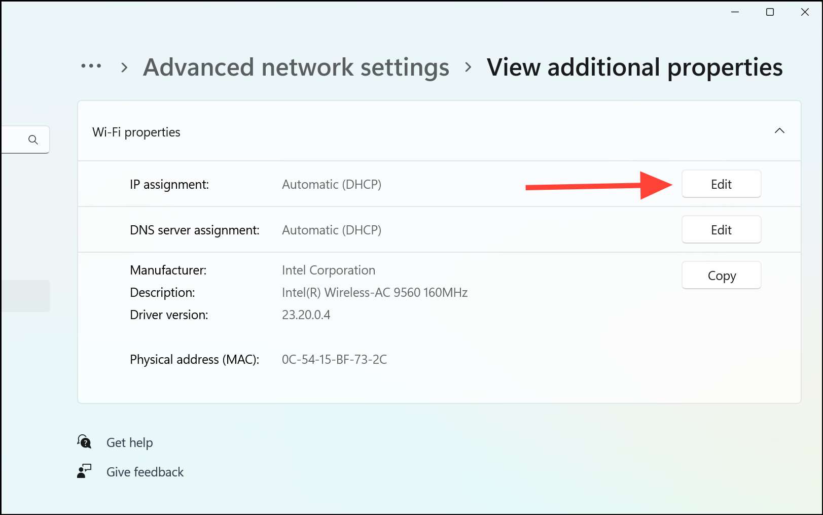
- In the pop-up window, choose 'Manual' from the drop-down menu.
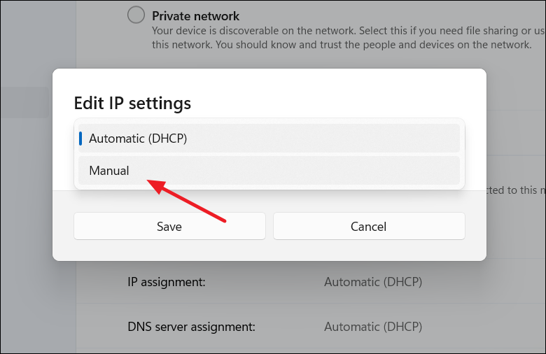
- Find the switch labeled 'IPv4' and flip it to the 'on' position. This enables your computer to connect to the internet using the IPv4 protocol.
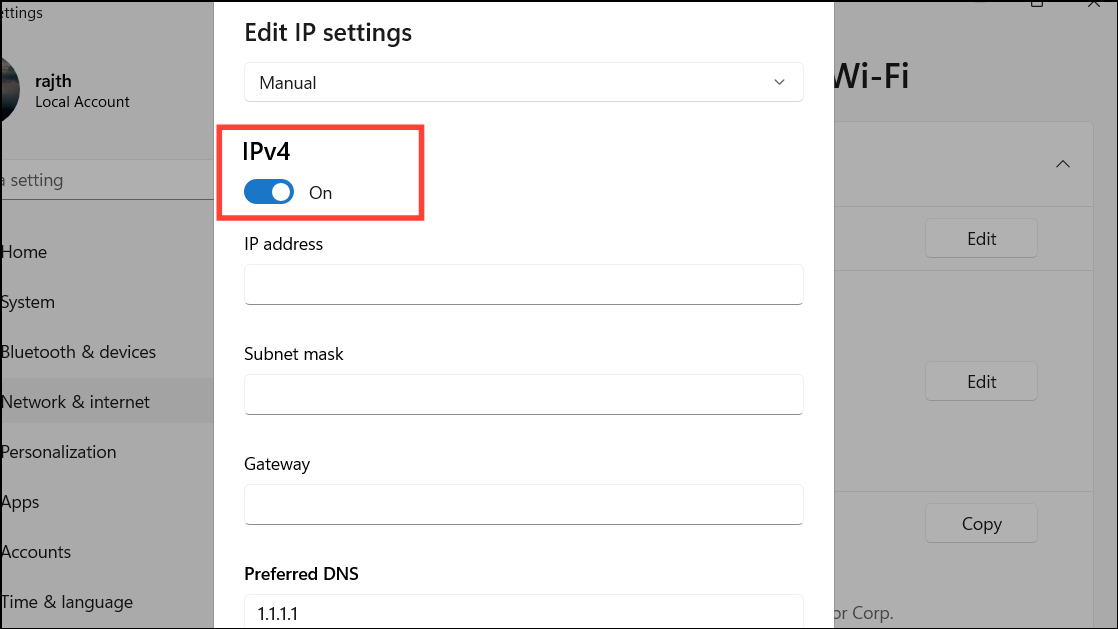
- Then, fill out your network details in the below fields:
- IP address: Choose a unique address from your router's range, typically between 192.168.0.2 and 192.168.0.254 .
- Subnet mask: Generally set to 255.255.255.0 for home networks, indicating your network's size.
- Gateway: Your router's IP address, acting as the central point for network traffic, often 192.168.0.1 or 192.168.1.1 . Find it on your router or via the ipconfig command .
- Preferred DNS: Input the IP of a DNS server like 1.1.1.1 (Cloudflare) or 8.8.8.8 (Google) , translating website names into IP addresses.
- Alternate DNS: Choose a secondary DNS, such as 1.0.0.1 (Cloudflare) , to ensure continuity if the primary is down.
- After filling in the details, click 'Save' to set the static IP address to your PC.
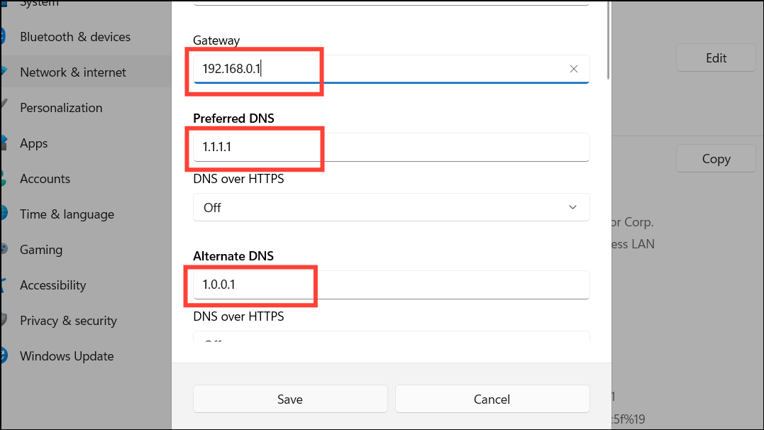
2. Enable Network Discovery
Turning on Network Discovery makes your PC visible to other devices on your local network, facilitating tasks like file sharing.
- Open Settings > Network & Internet > Advanced network settings.
- Click on 'Advanced sharing settings'.
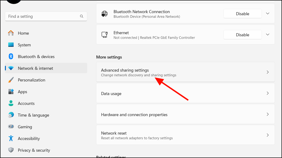
- Expand the 'Private networks' option and turn on the 'Network discovery' toggle. Then check the box 'Set up network connected devices automatically'.
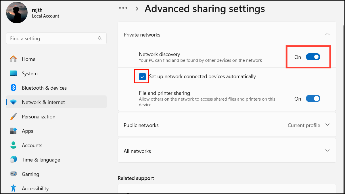
- Then, expand the 'Public networks' option and turn on the 'Network discovery'.
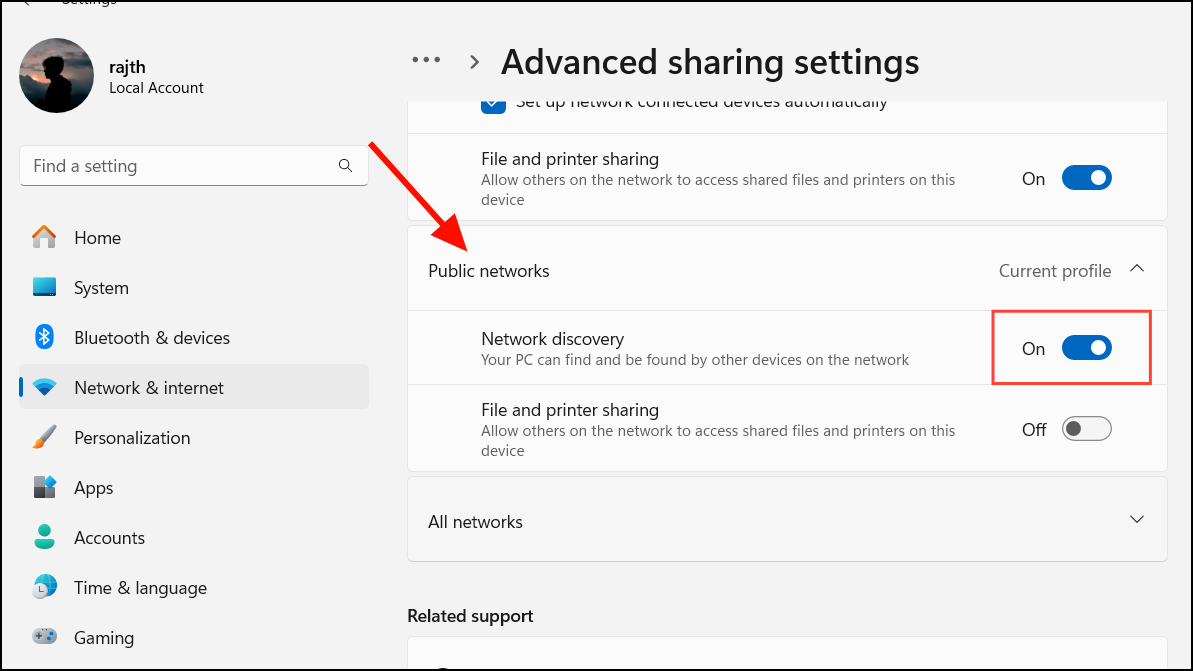
Configuring Your Router
Access your router settings to enable UPnP, manage port forwarding, activate DMZ mode, or edit the configuration file for tailored NAT adjustments.
Access Router Settings
- Open your browser and log in to your router’s web interface. To do this, type the default gateway address ` http://192.168.0.1 ` or http://192.168.1.1 in the address bar and hit Enter .
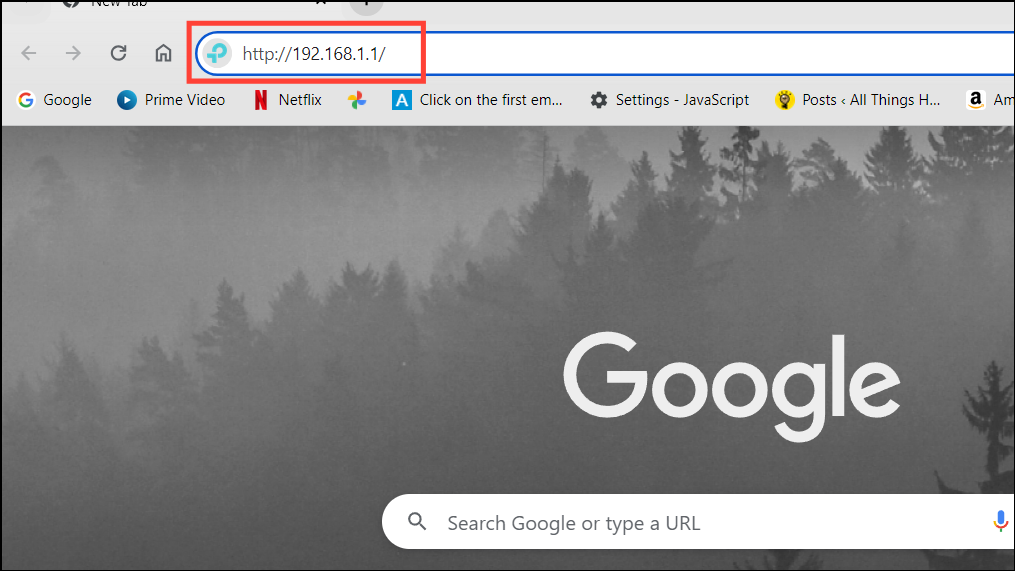
- Log in with your credentials (found in your router's manual or online).
Method 1: Enable UPnP (Universal Plug and Play)
Universal Plug and Play (UPnP) simplifies device communication on your network, essential for gaming and peer-to-peer connections.
- Once you are in the router settings, find UPnP settings (often under 'Advanced' or 'NAT Forwarding').
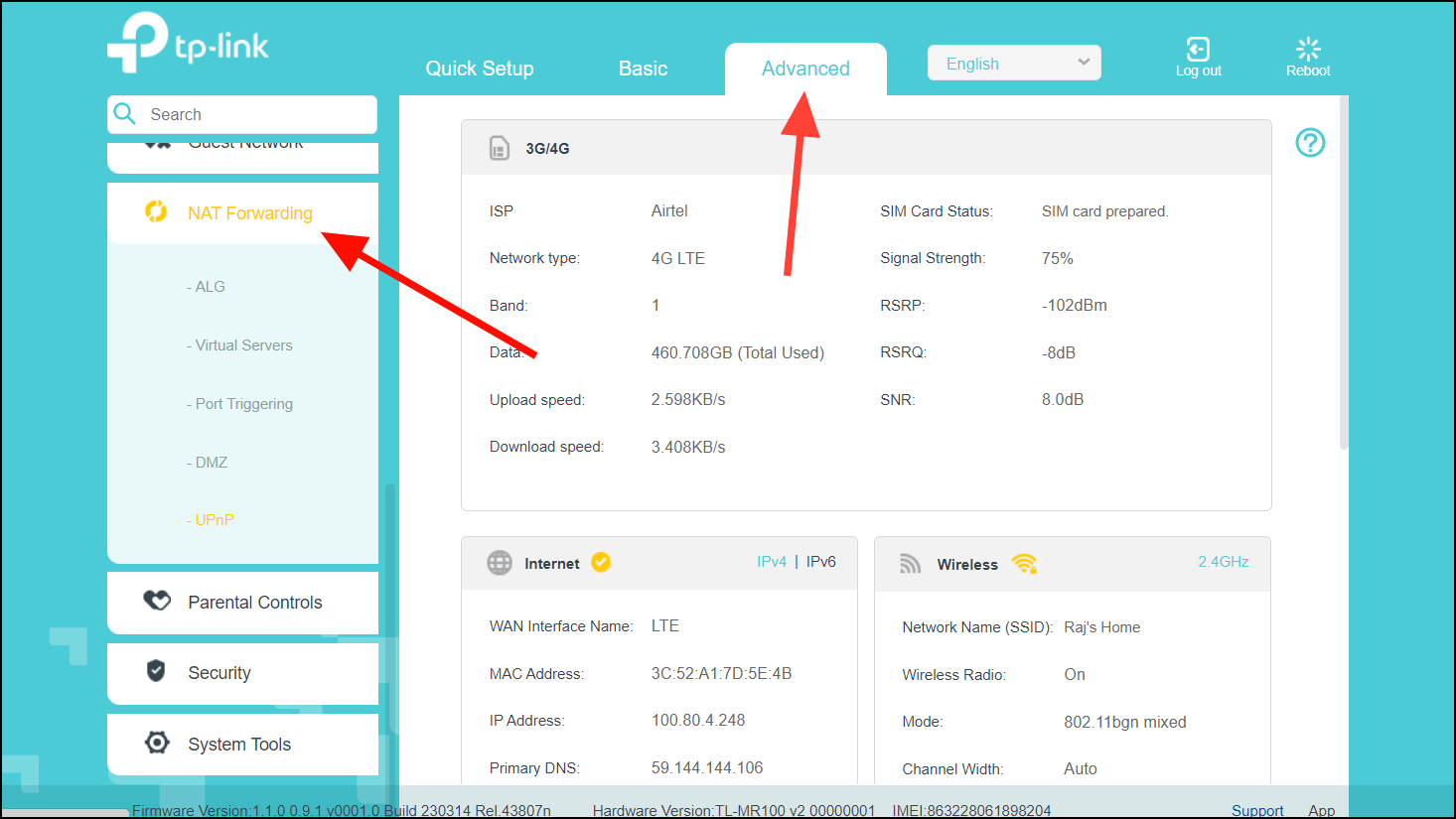
- Under NAT Forwarding, select the ‘UPnP’ tab and turn on the ‘UPnP’ switch.
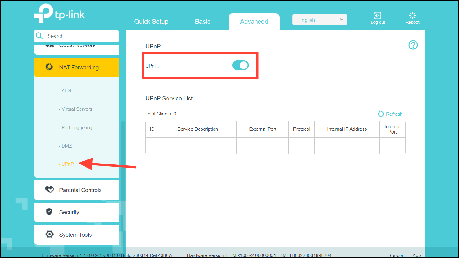
- Restart your router. After the reboot, your NAT Type will no longer be strict.
Method 2: Port Forwarding
Manual port forwarding allows specific ports to be open, improving connectivity for certain applications. This method is more secure but requires specific port information.
- First, log in to your router web app.
- Go to the 'Advanced' tab, look for the 'NAT Forwarding' or 'Forwarding' options and select it. If you don't have an Advanced tab or section, find and select 'NAT Forwarding' or 'Forwarding'.
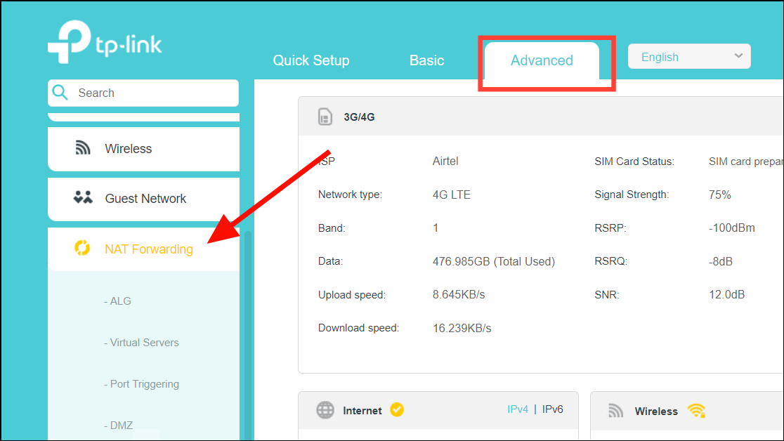
- In the left panel, expand the 'Forwarding' or 'NAT Forwarding' section and click on 'Port Triggering' or 'Port Forwarding'.
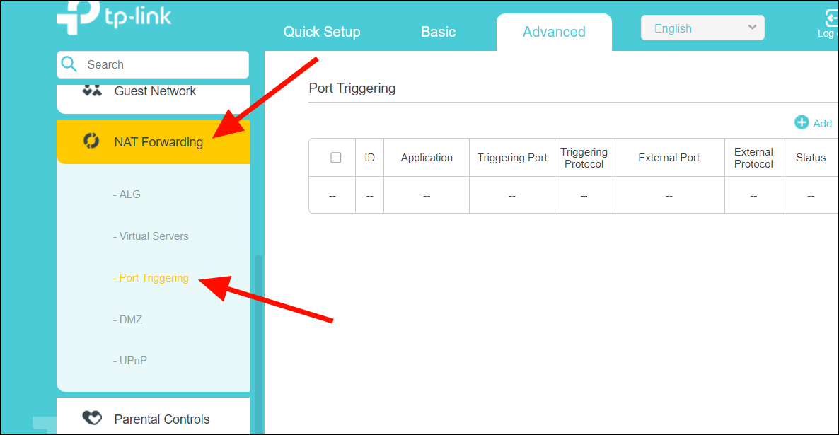
- Now, click the 'Add' or 'Add New' button to create a new port forwarding entry.
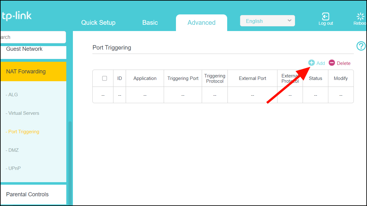
- In the 'Adding Port Forwarding Entry' window, fill in the fields for 'Service Name' or 'Application' with the name of your application or game, and 'Device IP Address' (if available) with your computer's static IP address you set, whether it's connected via Ethernet or Wi-Fi.
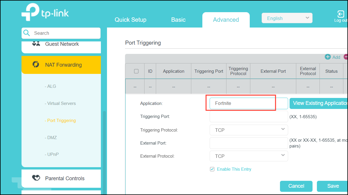
- To select an app from a list of existing options, simply click the 'View Existing Applications" button.
- Select the type of port (UDP or TCP) for both 'Triggering Protocol/Internal' and 'External Protocol' depending on the specific requirements of the game or apps. Some games or apps might use only UDP, some only TCP, and others might use both. But make sure to choose the same protocol type for both ports.
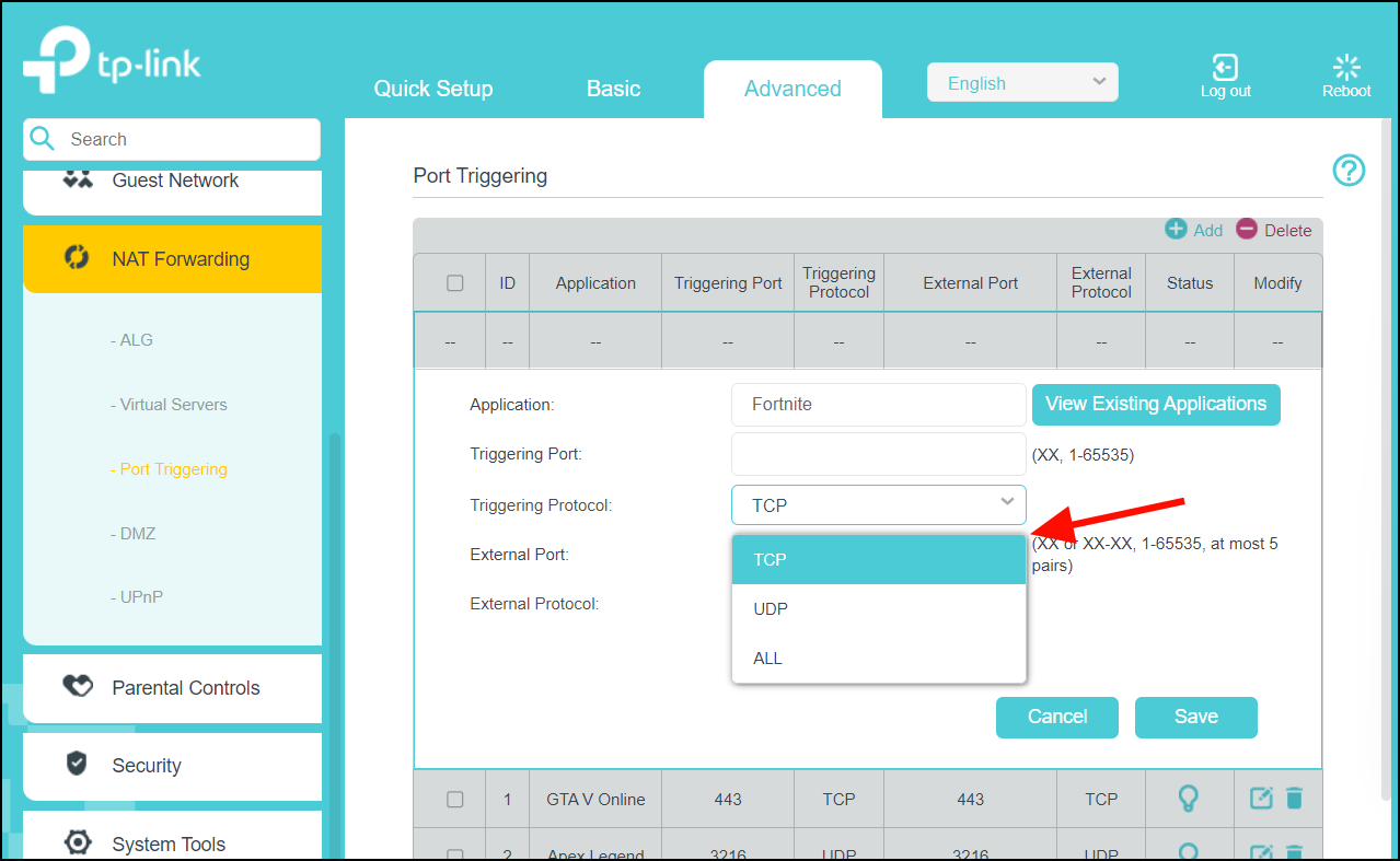
- Then, enter the same port number for 'Triggering Protocol' and 'External Protocol' whether you're using UDP or TCP. For example, we are using the port '5062' with TCP protocol for the Fortnite game.
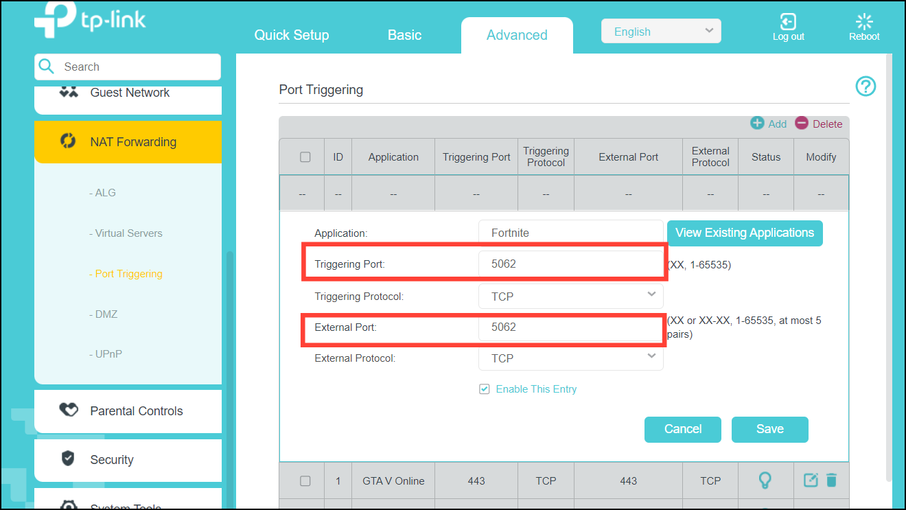
- Unless your app or game requires a single protocol type (TCP or UDP), you can streamline port forwarding by selecting 'All' in the Protocols field. This opens ports for both protocols for smooth performance.
- Finally, click 'Save' to save the port forwarding rule.
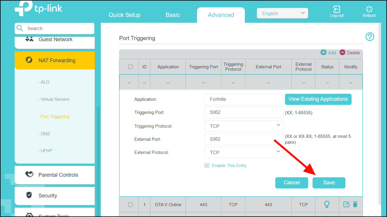
- Your port forwarding rule is now saved. You can easily enable or disable the rule using the buttons under the 'Status' column.
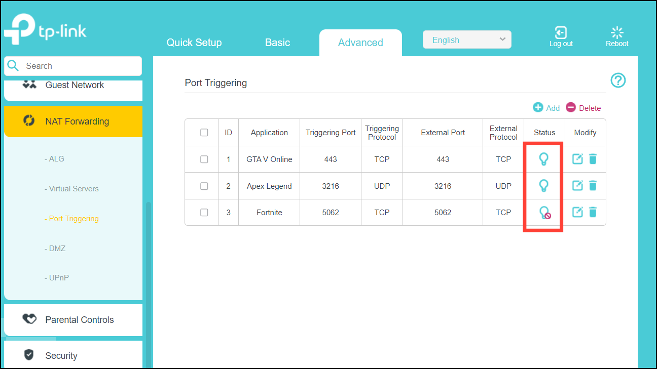
- Once it's done, restart your router. After it comes back online, launch your game again and check your NAT type. It should be set Open NAT type now.
Method 3: Enable DMZ (Demilitarized Zone) Mode
Some routers have a DMZ option that allows you to place a device outside the local network. You can quickly enable DMZ mode if you can't set up port forwarding or change other router settings. While this can potentially solve NAT issues, it's a less secure option.
- Open your router's web configuration page and head over to your router's 'Advanced' settings.
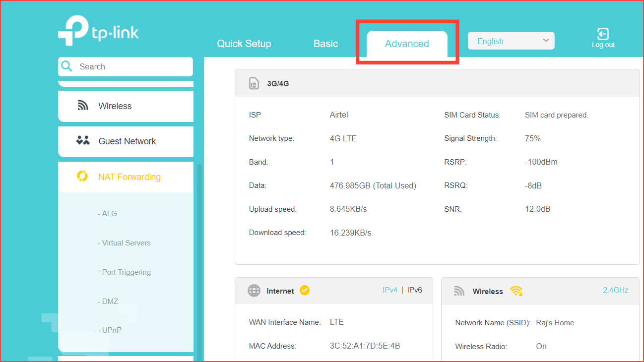
- In the left panel, expand 'NAT Forwarding' or 'Forwarding' and click 'DMZ' option.
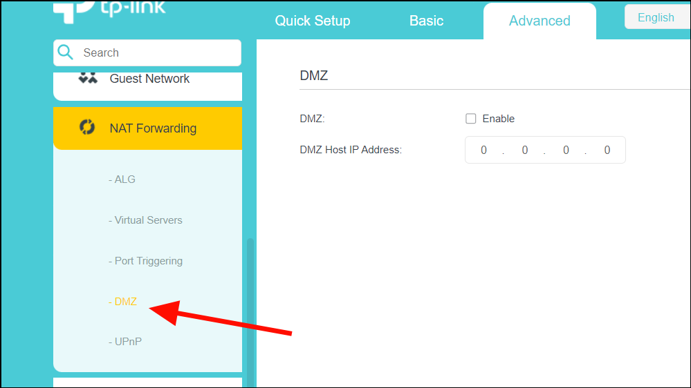
- Enable the 'DMZ' option, enter the static IP address you set for your PC, and click 'Save'.
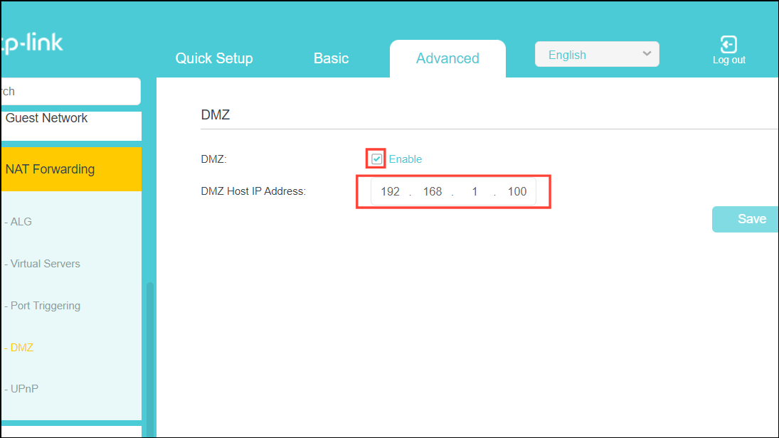
- Restart your router.
While this might be helpful for specific situations like video conferencing, remember it comes with significant security risks. DMZ mode may cause issues like latency and server quality for online gaming , but it will open all ports for an 'Open NAT'.
Method 4: Edit Router Configuration File to Change NAT Type
Editing your router's configuration file offers a powerful way to customize your Network Address Translation (NAT) type permanently. This will improve your online experiences without compromising device security.
The configuration file directly manages every router function including the assignment of IP addresses, stores Wi-Fi passwords, and even decides which apps get priority for fast internet access. Here’s how you can edit the configuration file.
- Open your favorite web browser and head to your router's configuration page. You can usually find the address printed on the bottom or back of your router.
- Go to the 'Advanced' tab in the web app and look for 'System Tools'. Then, select it.
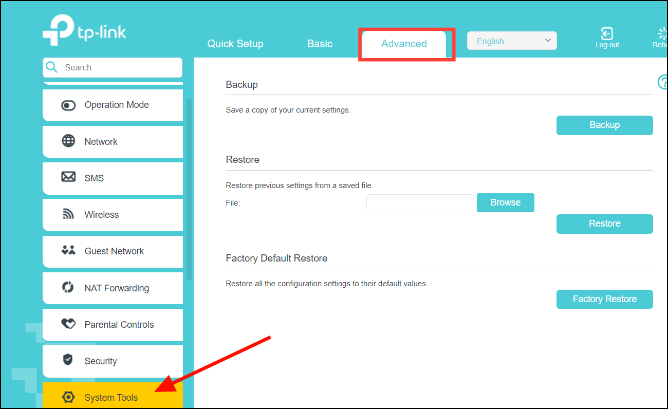
- Then, click on 'Backup & Restore' or 'Save and Restore Settings'. Before making any changes, make sure you save your current configuration. So, look for the backup option.
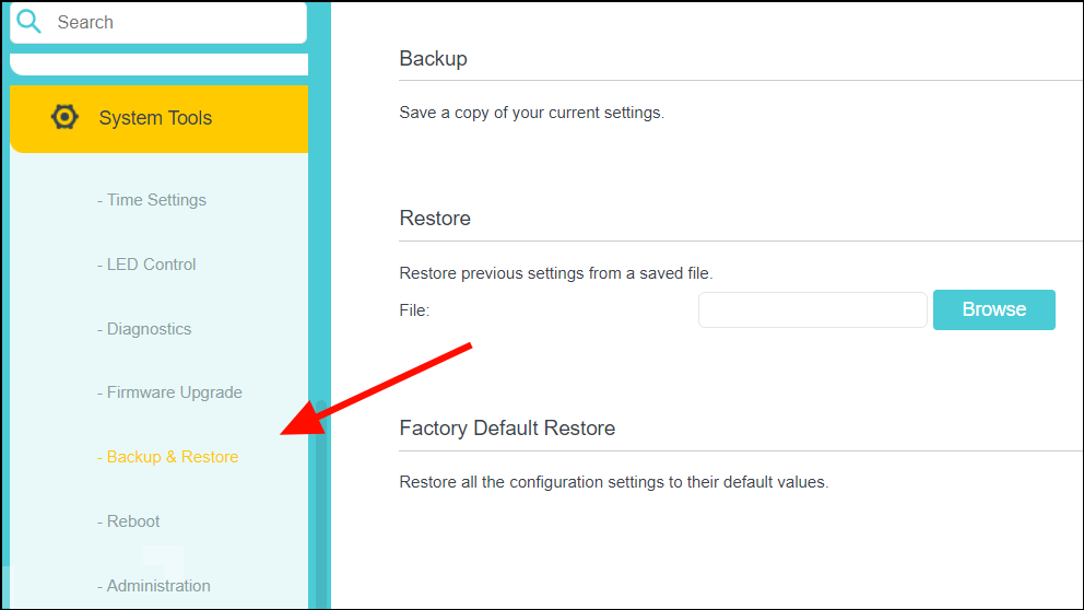
- Then, find and click the 'Backup' or 'Save Configuration' button. It usually has an option that will allow you to back up your router’s configuration.
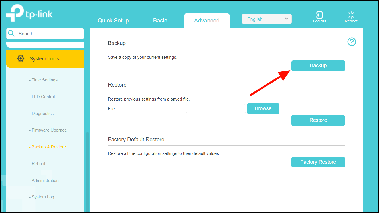
- In the Save as window, choose a location and click 'Save' to save the router configuration file. You can use the backup file to restore the settings in case something goes wrong.
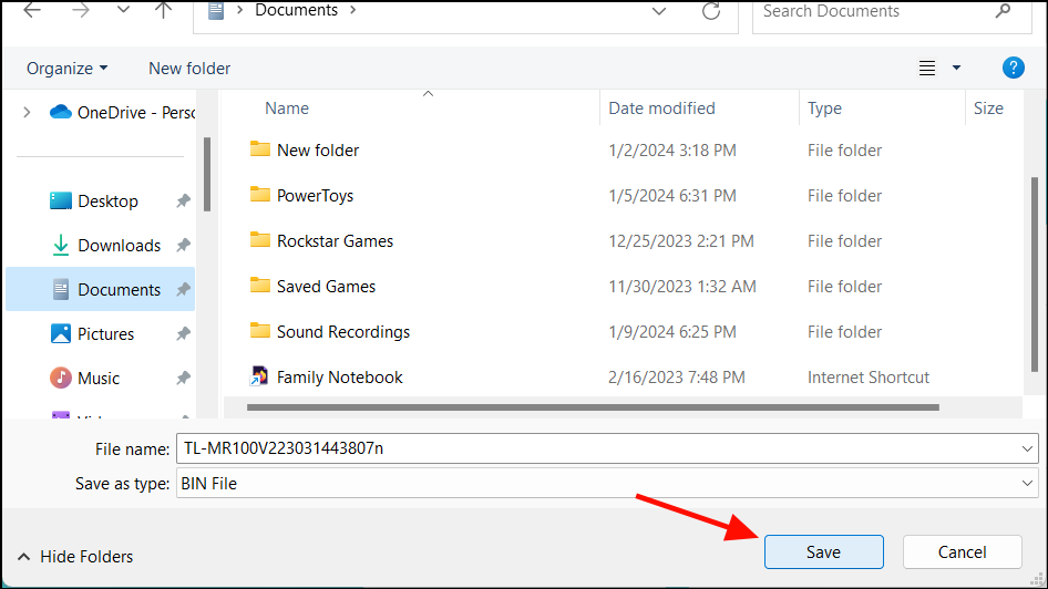
- If you are prompted to keep or discard the saved configuration file, click 'Keep'.
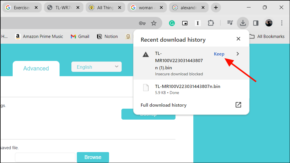
- After creating the backup file, locate it in your computer, make a duplicate copy, and save that second copy in a different, secure location.
- Now, you can edit the configuration file to change the NAT type. However, you can only do this if the file is in '.ini' format not '.bin' format.
- Right-click the file and select 'Open with' then 'Notepad'.
- Then, quickly find the connection.ini section by pressing Ctrl + F and typing it in the search bar.
- Then, look for the last bind text.
- Underneath the last 'bind' line, paste the following lines but replace the ports number (3478-3479) with those required by your specific game or app:
- If you need multiple ports for different apps, just copy and paste the same code you used for the first port, but change the port number in each new copy.
- Then, save the edited configuration file.
- Go back to your router's configuration page, where you previously backed up the file.
- Click the 'Browse' button under the Restore section. Find and select the updated configuration file you just saved.
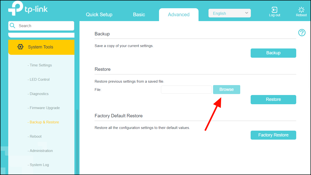
- Then, click 'Restore' to restore the settings.
- After that, reboot your router and check if the NAT type is changed on your app.
Enable UPnP using Windows Network Settings
If you cannot enable UPnP via router settings or your router doesn't have options for it, you can do it using Network Infrastructure.
Manually forwarding ports is like opening and closing these gates yourself, while UPnP acts like an automatic gatekeeper, opening ports for applications as needed.
- Open File Explorer and click on 'Network' at the bottom left corner.
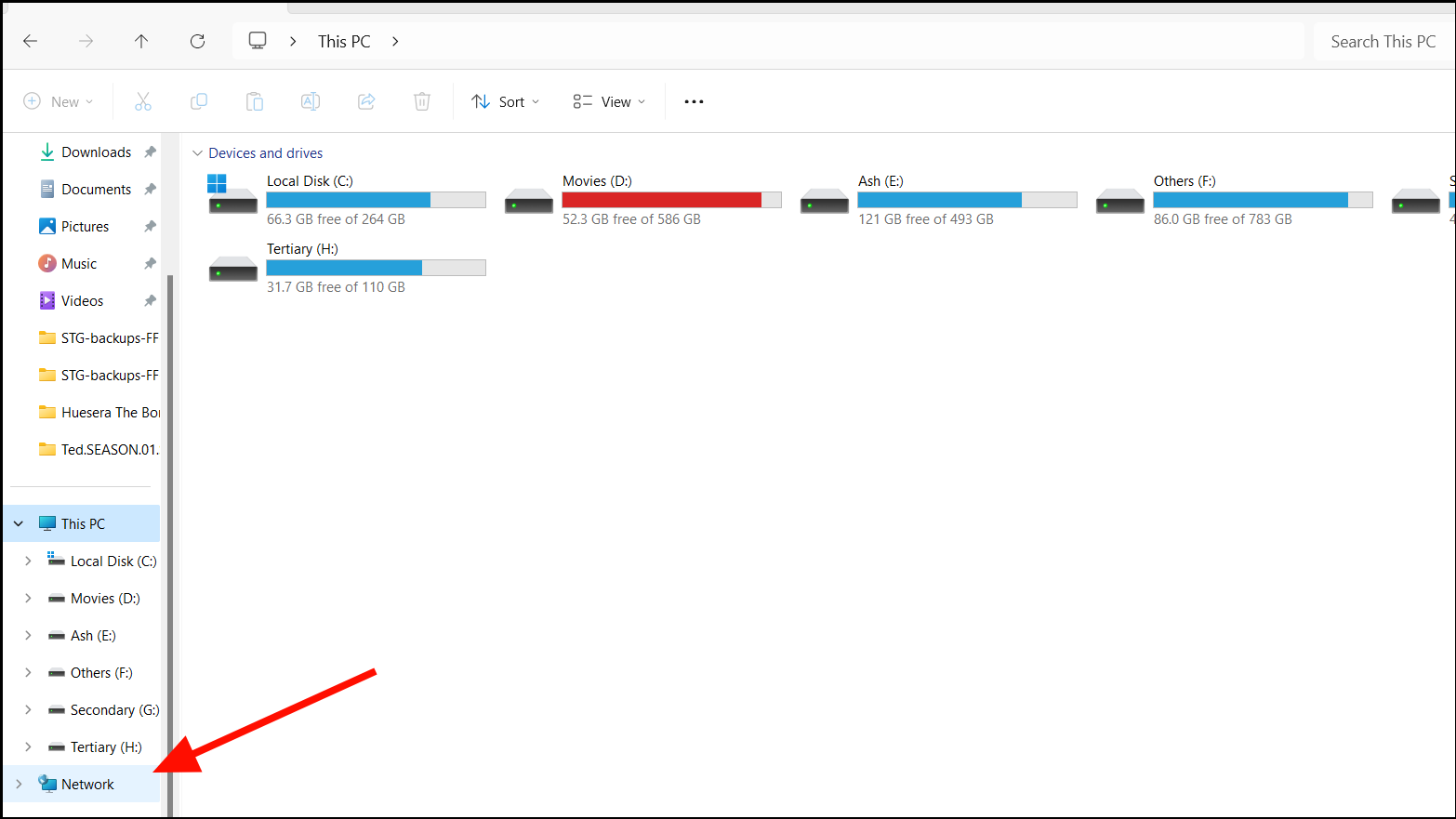
- Right-click the 'Network Adapter' (or "Network Infrastructure" if available) and choose 'Properties'.
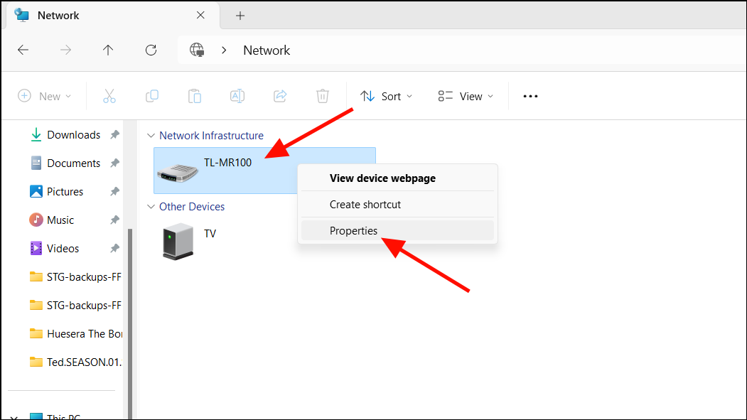
- In the newly opened window, click 'Settings'.
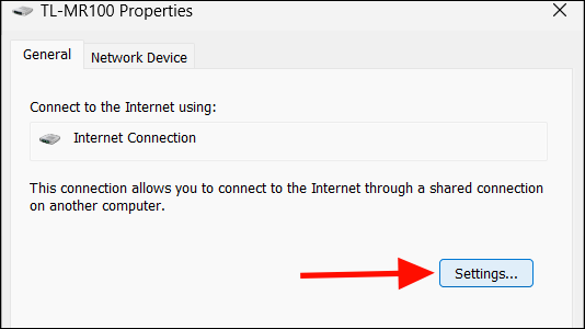
- After that, click 'Add' in the Advanced Settings window.
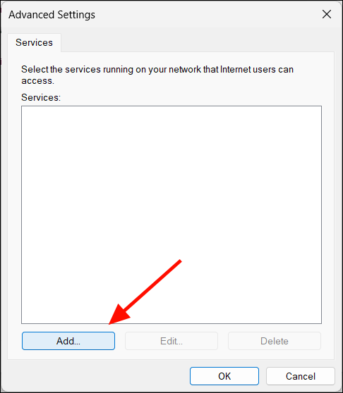
- Type a descriptive name like 'GTA V Online' in the Description of service field.
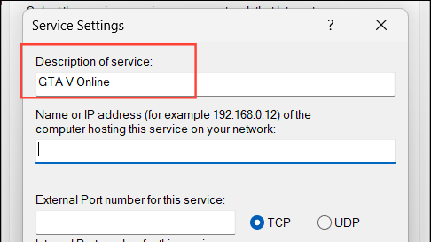
- Enter your IPv4 address in the Name or IP address field.
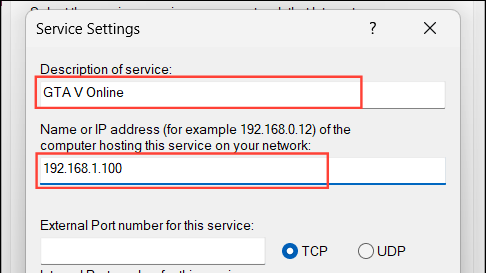
- Type the same port number specific to your game in both the 'External' and 'Internal Port Number' fields.
- Select your protocol type (UDP or TCP) and then click 'OK'.
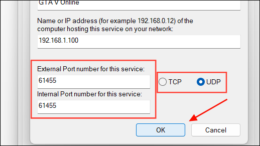
- Repeat the above steps for different services or apps.
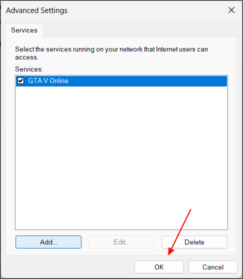
- Once it's done, click 'Apply' and then 'OK' on all open windows.
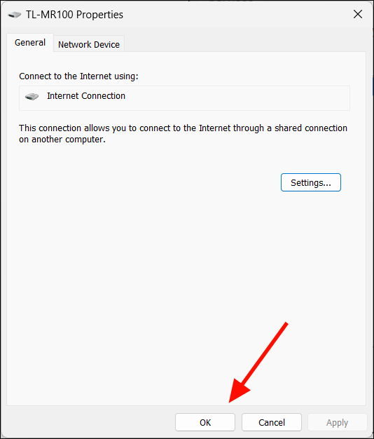
This method creates temporary port forwarding rules that reset every time you restart your router or disconnect your network. Then you will need to repeat the process each time you encounter a closed NAT type.
Verifying NAT Type Changes
After making changes, you can often check the NAT type directly in applications (like games) or via specific router settings. If not, below is a quick guide to check NAT type using Command Prompt in Windows 11.
- Verify the NAT Type in Application Settings. For most online games and some applications, you can find the NAT type displayed within the application’s network settings. Launch the application, navigate to its network or connection settings, and look for a section that displays the NAT type. This immediate feedback can help you understand if the adjustments have enhanced your connectivity as intended.
- Check the NAT Type in Your Router's Interface. Access your router's web interface by typing its IP address into your web browser. Log in with your credentials. Once inside, navigate to a section related to NAT settings, network, or status. Different routers have different terminologies, but you're looking for a page that shows your current NAT type. This method provides a direct insight from your router's perspective.
- Restart Your Router and PC. In some cases, changes to NAT types won't take effect until after a system restart. Turn off your router and PC, wait for a few moments, then turn them back on. This step ensures that all new configurations are loaded correctly and can solve connectivity issues that a simple refresh might not.
Security Considerations
- Always ensure your router's firmware is up to date to protect against vulnerabilities.
- Consider the risks associated with each NAT type, especially if enabling UPnP or DMZ.
- Regularly review and update your router's security settings.
Conclusion. Adjusting your NAT type in Windows 11 involves configuring your router and making corresponding settings adjustments on your PC. While changing NAT type can improve connectivity for certain applications, it's vital to understand and manage the security risks involved. Always maintain a balance between network accessibility and protection.

How to Code Using AI

Microsoft Copilot Pro Review: There is a lot of Unrealized Potential

How to Create a Custom Copilot GPT
Get all the latest posts delivered straight to your inbox., member discussion.

How to Fix Windows 11 Error "The Instruction at 0x00007FF referenced memory 0x0000000. The memory could not be written"

How to Fix "AMDRyzenMasterDriverV22 service failed to start" Error in Windows

What is VmmemWSA Process and How to Stop it From Consuming Excess Memory in Windows 11

How to Use Your Phone as a Webcam in Windows 11

How to Open Apps and Websites with Keyboard Shortcuts in Windows 11
IP and Network Assignment
The IP and network assignment setting in the Aruba Instant On mobile app allows you to configure internal/external DHCP and NAT for clients on employee networks or guest networks. You can configure one of the following settings on your device:
- Same as local network (default) —This setting is referred to as Bridged mode . Clients will receive an IP address provided by a DHCP service on your local network. By default, the default network created during setup is assigned as your local network. To assign other networks, select the network from the Assigned network drop-down. The VLAN ID will be assigned to your network based on your network assignment. This option is enabled by default for employee networks.
- Specific to this wireless network —This setting is referred to as NAT mode . Clients will receive an IP address provided by your Instant On devices. Enter the Base IP address of the Instant On AP and select the client threshold from the Subnet mask drop-down list. This option is enabled by default for guest networks.

The NAT node
Starting with GNS3 2.0, the NAT node became available. This node allows you to connect a topology to internet via NAT. The Internet node was deprecated in favor of this node, and the Cloud node.
Your topology will not be directly accessible from the internet or local LAN, when using the NAT node. If that is required, then the Cloud node should be used.
It’s useful when you need to download things from the internet, like packages, if nodes need to perform license check, etc…). It’s also much simpler to use than the preexisting Cloud node.
The NAT node requires either the GNS3 VM, or a Linux computer with libvirt installed. Libvirt is necessary, to create a virbr0 interface for this node to function.
By default, the NAT node runs a DHCP server with a predefined pool in the 192.168.122.0/24 range. It’s located in the End devices category:

To add the NAT node to a topology, drag and drop it into the workspace. You will be prompted to specify the server type you want to use, to run the NAT node. This article will use the Webterm docker container for testing internet connectivity, so the server type needs to be set to GNS3 VM, as this is being done on a Win10 workstation:

The NAT node will appear in the workspace:

Next, the Webterm docker container will also be added to the workspace:

The NAT node has a single interface named nat0:

To allow more than one topology node to have access to the internet, it will be necessary to connect a switch or router to the NAT node, and then connect the topology nodes to the other device.
For simplicity, the built-in ethernet switch will be connected to the NAT node, and the Webterm container will be connected to the switch:

You enable DHCP or manually configure static IP assignment to docker container like Webterm, by right-clicking on it while it’s shutdown, and then select “Edit config”:

A window will open, showing this container’s /etc/network/interfaces file:

To configure this container to use DHCP, you uncomment the two lines shown in the below image, and click Save:

(uncomment means removing the ‘#’ symbol at the front of those lines. That symbol causes the system to not read those lines, and are commonly used to add comments to code, which should not be processed)
Starting up the Webterm container (the NAT node will automatically be running from the moment it’s added to a topology) and opening its console will result in a VNC window appearing. Click on the “Restore” symbol in the upper-right corner of Firefox, to take it out of the fullscreen view:

Left-clicking on the black background and selecting “Terminal” will open terminal window:

You can use the terminal for a variety of things, but in this article, it’ll just be used to check the IP configuration of the container.
Using the ‘ifconfig’ command in the terminal will show that the DHCP running on the NAT node assigned this container the 192.168.122.200 address from its pool:

Back in Firefox, enter a URL in the address bar, to access a website:

You aren’t restricted to just using dynamic address assignment with the NAT node. You can also statically assign IP addressing on it, and still have internet access.
Stop the Webterm container, right-click it, and choose “Edit config” again.
This time, you’ll comment out the two lines for DHCP, and uncomment the lines in the Static IP section of the /etc/network/interfaces file;

In the above example, the Webterm container was statically assigned the 192.168.122.25/24 IP address and mask, its default gateway was set to 192.168.122.1 (the internal IP address of the NAT node), and the nameserver was set to 8.8.8.8, which is one of Google’s free public DNS servers.
Click Save, start the container, and console back into it. Opening a terminal and running “ifconfig” will show that the container is using the statically assigned IP address:

Entering a URL in the Firefox address bar will open a website:

- Knowledge Base
- Networking Solution
- Wi-Fi Access Points
- Advanced Features
- GWN76xx NAT & Firewall Guide
GWN76xx NAT & Firewall Guide
In this guide we will cover the Firewall rules for inbound and outbound traffic with which we can configure a set of rules that will either deny or allow it. With the firewall rule. This provides a centralized management for the entire network flow by selecting which SSID to have a rule or a set of rules applied on one or multiple SSIDs
This guide will also include the Network Address Translation (NAT) configuration on GWN Access points, so in NAT mode, clients will get the IP addresses from the specified NAT pool, while the communication and clients connecting to different APs are isolated from each other.
A firewall is a set of security measures designed to prevent unauthorized access to a networked computer system. It is like walls in a building construction, because in both cases their purpose is to isolate one “network” or “compartment” from another.
To protect private networks and individual machines from the dangers of Internet, a firewall can be employed to filter incoming or outgoing traffic based on a predefined set of rules called firewall policies.
Traffic Rules: Used to control incoming/outgoing traffic and taking actions for specified rules such as Permit and Deny.
Outbound Rules
This section allows user to control the outgoing traffic from clients connected to certain SSIDs or all SSIDs by manually setting up the policies to either deny or permit the traffic based on protocol type and by specifying destinations.
To create a new outbound rule:
- Select the Service Protocol to apply the rule on like ICMP , HTTP … Any or Custom .
- Set Policy to either Permit or Deny .
- Select Destination type whether Particular Domain , IP Address , Particular Network or All .
- Select the SSID (s) to have the rule applied on.
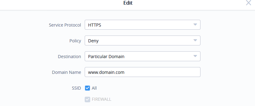
The following table lists and describes the available options:
The Outbound Rules will be displayed as the figure below:
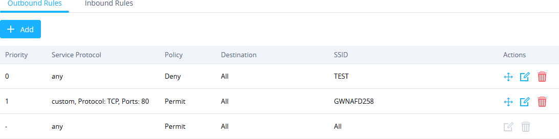
Inbound Rules
User can define inbound rules by setting up actions to either block or accept incoming from specific and/or to a specific destination.
To create a new inbound rule:
- Select the Service Protocol to be apply the rule on like ICMP , HTTP, Any, Custom.. .
- Set Policy to Permit or Deny.
- Select Source to either All , Particular IP, or Particular Network . (IP field must be enter if selecting Particular IP, additionally Netmask field must be entered if selecting Particular Network).
- Select Destination to either All , Particular IP , Particular Domain or Particular Network . (IP field must be enter if selecting Particular IP, additionally Netmask field must be entered if selecting Particular Network, while Domain Name must be entered if selecting Particular Domain).
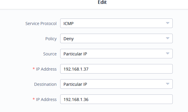
GWN76xx NAT feature defines an address pool from which the Wi-Fi clients will acquire their IP address so that the access point acts as a lightweight home router.
- This option cannot be enabled when Client Assignment IP is set to Bridge mode.
- This option is not supported in GWN7610.
In order to use the lightweight NAT service of the GWN76XX AP, please proceed as follow:
- In the Client IP Assignment select NAT option and configure the rest of the parameter like password and Access points involved.
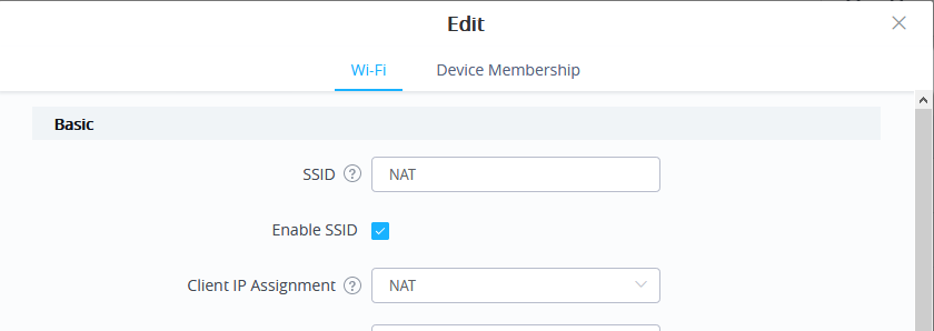
- Then proceed from Service → DHCP Server → NAT Pool , in order to configure the Gateway, with which the client will communicate with along with DHCP Server Subnet Mask, DHCP Lease Time and DHCP Preferred/Alternate DNS:
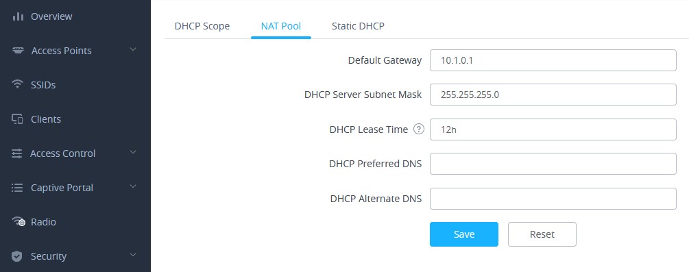
- Proceed from Clients page to be informed on the IP the clients have acquired.
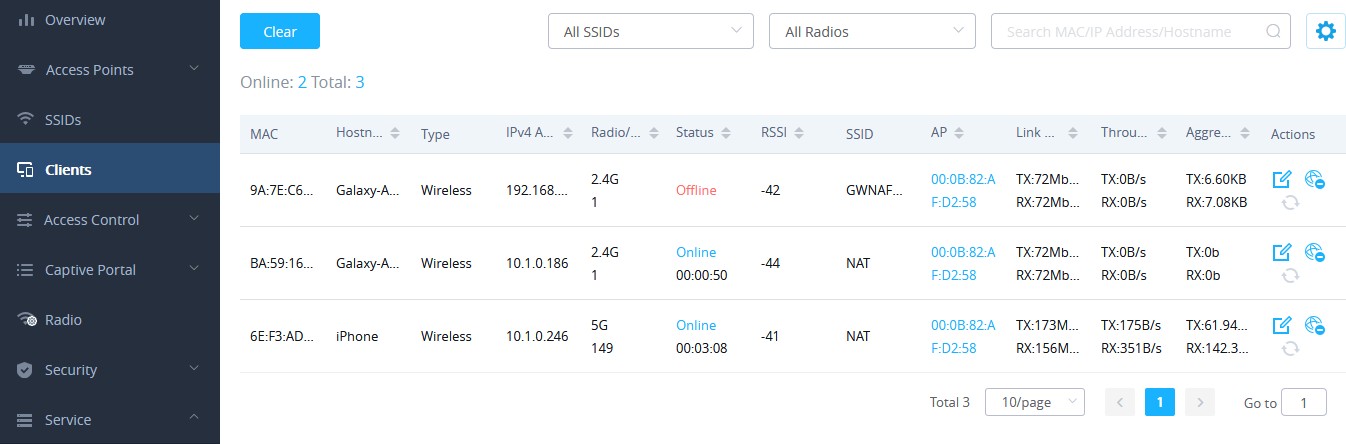
Was this article helpful?
Related articles.
- GWN7664(LR) - Port Aggregation Guide
- GWN76xx - Wi-Fi and LED Scheduling Guide
- GWN76xx - Client Isolation
- GWN76xx - Client Bridge Guide
- GWN76xx SNMP Guide
- GWN76xx - Rogue AP Detection Guide
Leave a Comment
You must be logged in to post a comment.
Meraki Community
- Community Platform Help
- Contact Community Team
- Meraki Documentation
- Meraki DevNet Developer Hub
- Meraki System Status
- Technical Forums
Meraki Assign NAT Mode WiFi - Internet Traffic Flow Preference?
- Subscribe to RSS Feed
- Mark Topic as New
- Mark Topic as Read
- Float this Topic for Current User
- Printer Friendly Page

- Mark as New
- Report Inappropriate Content
Solved! Go to solution.

View solution in original post
- All forum topics
- Previous Topic

- New April 1: And we're live! New community look & feel is here!
- March 27: [LAUNCH POSTPONED] Planned downtime for the launch of the new Community look & feel
- March 26: New community look & feel, coming soon!
- Installation 201
- Interference 76
- RF Spectrum 93
- Community guidelines
- Cisco privacy
- Khoros privacy
- Terms of service

How to Change NAT Type on Windows 11/10
- Changing the NAT type from strict to open can improve network connectivity and reduce network-related issues when playing multiplayer games online.
- You can change your NAT type on Windows by enabling Discovery Mode, UPnP, or port forwarding.
- Port forwarding provides greater control over open ports and enhances security compared to UPnP, but it requires knowing the specific TCP and UDP ports used by your game.
You may want to change your NAT type from strict to open when playing multiplayer games online. A strict or moderate NAT type may cause network problems when joining a game party, like abrupt disconnections, lags, and making it difficult to host matches.
You can change the NAT type on Windows to ease restrictions, resulting in a faster and more reliable network connection. But you must balance your needs with potential security risks when changing the NAT.
What Is NAT, and What Are the NAT Types?
Network Address Translation (NAT) is a feature in routers (and firewalls) that translates the private IPv4 address from devices in your home and office to the public IPv4 address assigned to your router by the ISP and vice versa. NAT helps address the limited number of public IPv4 addresses available worldwide.
A NAT type describes the status of your network connection. The three NAT types are Strict, Moderate, and Open.
- NAT Type Strict: It is the most secure of the NAT types but also the most restrictive one. Users with a Strict NAT type can join games hosted by a system with an Open NAT type. However, the connection is dropped if a system with a Moderate NAT type joins the same game.
- NAT Type Moderate : It is moderately secure and opens a few ports. Systems with a Moderate NAT type can join other systems using the Moderate or Open NAT type.
- NAT Type Open : Choose Open NAT if you want to host matches. It has no restrictions and facilitates data transfer between all devices without restrictions, irrespective of their NAT type or firewall configuration.
Your default NAT type depends on your router configuration. If you experience network-related issues, changing your NAT type from Strict or Moderate to Open can help. However, be wary of potential security risks associated with changing your NAT type to Open.
How to Set a Static Private IP Address
Whether you want to change the NAT type using the UPnP method or port forwarding, you'll need a static IP address to make it work. Since most routers assign a dynamic IP address, you must manually configure a static IP for your Windows device.
If you already have a static IP address assigned to your device, skip to the following steps to change the NAT type. If not, follow the below steps to set a static IP address on your Windows computer :
- Press Win + R to open Run .
- Type cmd and click OK to open Command Prompt .
- In Command Prompt, type the following command to view your network information: ipconfig
- For this guide, we'll set up a static IP for the Ethernet adapter. So, scroll down to the Ethernet adapter section and note down the IPv4 Address , Subnet Mask , and Default Gateway .
- Next, press Win + I to open Settings .
- Go to Network & internet , and click on Ethernet to open the Ethernet adapter properties.
- Click the Edit button beside IP assignment.
- Select the Automatic (DCHP) drop-down and choose Manual.
- Toggle the switch to enable IPv4 .
- Enter the IP address by ensuring the first three octets of your IP address match the IPv4 address obtained using the ipconfig command—for example, type 192.168.0.200 . As you can see, we have kept the first three octets of the IP address ( 192.168.0 ) but changed the fourth octet to 200 from 101 .
- Enter the Subnet mask , and Default gateway address for the Ethernet adapter obtained using the ipconfig command.
- In the Preferred DNS field, enter 8.8.8.8 ; for Alternate DNS , enter 8.8.4.4 . This is a public DNS server offered by Google.
- Leave other settings as default and click Save to set up your static IP address for the device.
Once you have a static IP, you can follow the steps below to change the NAT type on your Windows computer.
1. Turn On Discovery Mode on Windows
Network Discovery is a built-in Windows feature to help you allow other computers on the network to detect your computer. You can turn On or Off the Network Discovery mode on Windows 10 from the Settings apps. Here's how to do it on Windows 11:
- Press Win + I to open Settings .
- Open the Network & internet tab in the left pane.
- Click on Advanced network settings .
- Scroll down and click Advanced sharing settings under the More settings section.
- Toggle the switch for Network Discovery to turn it on for public networks.
2. Enable UPnP On Your Router
You can change your NAT type to Open by enabling Universal Plug and Play (UPnP) in your router settings. This is the easiest way to change the NAT type, provided you can access your router configuration page. However, there are security concerns with the UPnP method , which hackers may exploit.
Note that the following steps apply to a TP-Link router. The process to enable UPnP may differ for routers from other manufacturers. Check your router's user manual or manufacturer knowledge base online for instructions.
Follow these steps to enable UPnP:
- Log in to your router's web-based utility. To do this, type the default gateway address (for example (http://192.168.0.1) in the search bar and press Enter. If not, here's how to find your router's IP address .
- On the router dashboard, open the Advanced tab.
- Click to expand NAT Forwarding in the left pane.
- Open the UPnP tab under NAT Forwarding .
- Toggle the switch to enable UPnP .
You can now close your router's web-based utility and check for any improvements in your network connectivity.
3. Change NAT Type Using Port Forwarding
Alternatively, you can use the safer port forwarding method to change your NAT type for a specific game title or application. While the process is a little complicated compared to UPnP, port forwarding gives greater control over open ports and their usage with enhanced security.
To create a new port forwarding entry, you'll need to know the TCP or UDP ports used for your specific game. For example, Call of Duty: Black Ops Cold War uses the following ports:
TCP: 3074, 27014-27050
UDP: 3074-3079
To find your game's UDP and TCP ports, perform a web search with your game title for port forwarding. Often, the game developers include port information for the game on their website.
Alternatively, go to portforward , select your game, and then your router name and model using the given options. On the following page, scroll down to locate the specific ports for your game. Port Forward keeps a database of ports for games on multiple platforms and for different router makers.
To change NAT type using Power Forwarding:
- Log in to your router's web app. In this instance, we'll use TP-Link's web-based utility.
- Open the Advanced tab.
- In the left pane, click to expand NAT Forwarding .
- Open the Port Forwarding tab.
- Click the + Add icon in the top right corner to create a new port forwarding entry.
- In the Add a Port Forwarding Entry dialog, type a name for Service Name . Make sure to add a name to make it easy to identify this port forwarding entry for future reference.
- In Device IP Address , type your computer's static IP address for Ethernet or Wi-Fi.
- Type your game's port number in the External and Internet Port fields. You can use a UDP or TCP port, but use the same port in both the External Port and Internal Port fields.
- Set the Protocol field to All .
- Once done, click Save to save the port forwarding entry.
The entry will be saved in the Port Forwarding table. You can enable or disable the entry using the Status toggle switch.
Apart from port forwarding, you can also change the NAT type by modifying your router's configuration file. However, some router manufacturers, including TP-Link, encrypt the configuration file, making it extremely difficult to make necessary modifications.
Changing NAT Type on Windows to Fix Network Issues
Changing the NAT type may be necessary to troubleshoot network-related issues. You can enable UPnP or turn on Network Discovery to ease network restrictions. However, we recommend port forwarding to reduce network restrictions without compromising network security.

ePMP: Configuring SM Network page for NAT Mode
The SM’s Network page is used to configure system networking parameters and VLAN parameters. Parameter availability is based on the configuration of the SM Network Page for NAT Mode .

Spanning Tree Protocol
Disabled: When disabled, Spanning Tree Protocol (802.1d) functionality is disabled at the SM.
Enabled: When enabled, Spanning Tree Protocol (802.1d) functionality is enabled at the SM, allowing for the prevention of Ethernet bridge loops.
DHCP Server Below SM
Disabled: This blocks DHCP servers connected to the SM’s LAN side from handing out IP addresses to DHCP clients above the SM (wireless side).
Enabled: This allows DHCP servers connected to the SM’s LAN side to assign IP addresses to DHCP clients above the SM (wireless side). This configuration is typical in PTP links.
NAT Helper For SIP
Disabled: When disabled, the SM does not perform any deep packet manipulation on the SIP request packet from a SIP Client.
Enabled: When enabled, the SM in NAT mode replaces the Source IP within the SIP request to the Wireless IP of the SM. Please note that this translation is often times handled by the SIP server so this option may not always be needed.
The Link Layer Discovery Protocol (LLDP) is a vendor-neutral link layer protocol (as specified in IEEE 802.1AB) used by ePMP for advertising its identity, capabilities, and neighbors on the Ethernet/wired interface.
Disabled: ePMP does not Receive or Transmit LLDP packets from/to its neighbors.
Enabled : ePMP can Receive LLDP packets from its neighbors and Send LLDP packets to its neighbors, depending on the LLDP Mode configuration below.
Receive and Transmit: ePMP sends and receives LLDP packets to/from its neighbors on the Ethernet/LAN interface.
Receive Only : ePMP receives LLDP packets from its neighbors on the Ethernet/LAN interface and discovers them.

- Contact Sales
Meraki Campus LAN; Planning, Design Guidelines and Best Practices
- Last updated
- Save as PDF
Introduction
The enterprise campus .
The enterprise campus is usually understood as that portion of the computing infrastructure that provides access to network communication services and resources to end-users and devices spread over a single geographic location. It might span a single floor, building or even a large group of buildings spread over an extended geographic area. Some networks will have a single campus that also acts as the core or backbone of the network and provide inter-connectivity between other portions of the overall network. The campus core can often interconnect the campus access, the data centre and WAN portions of the network. In the largest enterprises, there might be multiple campus sites distributed worldwide with each providing both end-user access and local backbone connectivity. From a technical or network engineering perspective, the concept of campus has also been understood to mean the high-speed Layer-2 and Layer-3 Ethernet switching portions of the network outside of the data centre. While all of these definitions or concepts of what a campus network is are still valid, they no longer completely describe the set of capabilities and services that comprise the campus network today.
The campus network, as defined for the purposes of the enterprise design guides, consists of the integrated elements that comprise the set of services used by a group of users and end-station devices that all share the same high-speed switching communications fabric. These include the packet-transport services (both wired and wireless), traffic identification and control (security and application optimization), traffic monitoring and management, and overall systems management and provisioning. These basic functions are implemented in such a way as to provide and directly support the higher-level services provided by the IT organization for use by the end-user community.
This document provides best practices and guidelines when deploying a Campus LAN with Meraki which covers both Wireless and Wired LAN.
Wireless LAN
Planning, design guidelines and best practices .
Planning is key for a successful deployment and aims in collecting/validating the required design aspects for a given solution. The following section takes you through the whole design and planning process for Meraki Wireless LAN. Please pay attention to the key design items and how this will influence the design of WLAN but also other components of your architecture (e.g. LAN, WAN, Security, etc).
Planning Your Deployment
The following points summarizes the design aspects for a typical Wireless LAN that needs to be taken into consideration. Please refer to Meraki documentation for more information about each of the following items.
- Get an estimation of the number of users per AP (Influenced by the AP model, should be the outcome of a coverage survey AND a capacity survey )
- Determine the total number of SSIDs that are required ( do not exceed 5 per AP or generally speaking per "air" field such that 802.11 probes of no more than 5 SSIDs compete for airtime )
- For each of your SSIDs, determine their visibility requirements (Open, Hidden , Scheduled , etc) based on your policy and service requirements
- For each of your SSIDs, determine their association requirements (e.g Open, PSK, iPSK , etc) based on the clients' compatibility as well as the network policy
- SSID encryption requirements (e.g WPA1&2, WPA2, WPA3 if supported, etc). Please verify that it's supported on all clients connecting to this SSID and choose the lowest common denominator for a given SSID .
- Client Roaming requirements (if any) per SSID and how that will reflect on your Radio and network settings (e.g. Layer 2 roaming, Layer 3 roaming, 802.11r, OKC, etc). Review recommendations and pay attention to caveats mentioned in the following section.
- Wireless security requirements per SSID (e.g Management Frame Protection , Mandatory DHCP, WIPS , etc)
- Splash pages needed on your SSIDs ( e.g. Meraki Splash page, External Captive Portal, etc) and what is the format of your splash page (e.g. Click through, sign-on challenge, etc )
- Splash page customizations ( e.g welcome message, company logo, special HTML parameters, etc )
- Is it required to have Active Directory Integration for any of your SSIDs (What is the connectivity to AD server? IP route, VPN ,etc)
- Do you require an integration with a Radius Server (What is the connectivity to Radius server, How many Radius servers, Do you need to proxy Radius traffic, Any special EAP timers, etc, Will CoA be required, Dynamic Group Policy assignment via Radius, Dynamic VLAN assignment via Radius, etc)
- Client IP assignment and DHCP (Which SSID mode is suitable for your needs, which VLAN to tag your SSID traffic, etc)
- If you are tagging SSID traffic, ensure that the Access Point is connected to a trunk switch port and that the required VLANs are allowed
- Do you need to tag Radius and other traffic in a separate VLAN other than the management VLAN? (Refer to Alternate Management Interface )
- What are your traffic shaping requirements per SSID (e.g Per SSID, per Client, per Application)
- What are your QoS requirements per SSID (Per Application settings). Remember, you will need to match this on your Wired network.
- Do you need group policies ? (e.g. Per OS group policy, Per Client group policy, etc)
- What are the wired security requirements per SSID (e.g Layer 2 isolation , IPv6 DHCP guard, IPv6 RA guard, L3/7 firewall rules, etc)
- Are you integrating Cisco Umbrella with Meraki MR (Requires a valid LIC-MR-ADV license or follow the manual integration guid e)
- How do you want your SSIDs to be broadcasted (e.g. On all APs, specific APs with a tag, all the time, per schedule, etc)
- Is BLE scanning required?
- Is BLE beaconing required (What UUIDs and assignment method)
- What Radio profile best suits your AP(s) (e.g Dual-band, Steering, 2.4GHz off, channel width, Min and Max Power, Bit rate, etc)
- Do you need multiple Radio profiles (e.g. per zone, per AP, per location, etc)
- If you require end-to-end segmentation inclusive of the Wireless edge (Classification, Enforcement, etc.) using Security Group Tags (Requires LIC-MR-ADV license)
- If enabling Adaptive Policy , choose the assignment method (Static vs Dynamic via Radius) and SGT per SSID
- Follow the guidance when configuring your Radius server (e.g. Cisco ISE) to enable dynamic VLAN/Group-Policy/SGT assignment
- For energy saving purposes, consider using SSID scheduling
Design Guidelines and Best Practices
To digest the information presented in the following table, please find the following navigation guide:
- Item : Design element (e.g. Wireless roaming)
- Best Practices : Available options and recommended setup for each ( e.g. Bridge mode for seamless roaming )
- Notes : Additional supplementary information to explain how a feature works ( e.g. For NAT mode SSID, the AP runs an internal DHCP server)
- Caution/Caveat/Consideration : Things to be aware of when choosing a design option and/or implications to the other network components ( e.g. Layer 3 roaming mode requires AP to AP access on port UDP 9358 )
Please pay attention to all sections in the below table to ensure that you get the best results of your Wireless LAN design
Wired LAN
Introduction .
A traditional Campus LAN Solution will reflect a hierarchical architecture with the following layers:
- Access Layer
- Distribution Layer
When designing your Wired Campus LAN, it is recommended to start planning in a bottom-up approach (i.e. start at the Access Layer and go upwards). This will simplify the design process and ensure that you have taken into account the design requirements from an end to end perspective. As always, the design process should be done in iterations revising each stage and refining the design elements until the desired outcome can be achieved.
Here's an explanation of each layer in details and what design aspects should be considered for each:
Access Layer
The access layer is the first tier or edge of the campus. It is the place where end devices (PCs, printers, cameras, and the like) attach to the wired portion of the campus network. It is also the place where devices that extend the network out one more level are attached—IP phones and wireless access points (APs) being the prime two key examples of devices that extend the connectivity out one more layer from the actual campus access switch. The wide variety of possible types of devices that can connect and the various services and dynamic configuration mechanisms that are necessary, make the access layer one of the most feature-rich parts of the campus network.
Distribution Layer
The distribution layer in the campus design has a unique role in that it acts as a services and control boundary between the access and the core. It's important for the distribution layer to provide the aggregation, policy control and isolation demarcation point between the campus distribution building block and the rest of the network. It defines a summarization boundary for network control plane protocols (OSPF, Spanning Tree) and serves as the policy boundary between the devices and data flows within the access-distribution block and the rest of the network. In providing all these functions the distribution layer participates in both the access-distribution block and the core. As a result, the configuration choices for features in the distribution layer are often determined by the requirements of the access layer or the core layer, or by the need to act as an interface to both.
Core Layer
The campus core is in some ways the simplest yet most critical part of the campus. It provides a very limited set of services but yet must operate as a non-stop 7x24x365 service. The key design objectives for the campus core must also permit the occasional, but necessary, hardware and software upgrade/change to be made without disrupting any network applications. The core of the network should not implement any complex policy services, nor should it have any directly attached user/server connections. The core should also have the minimal control plane configuration combined with highly available devices configured with the correct amount of physical redundancy to provide for this non-stop service capability.
The following table compares between the main functions and design aspects of the three campus layers:
Collapsed Core Layer
One question that must be answered when developing a campus design is this: Is a distinct core layer required? In those environments where the campus is contained within a single building—or multiple adjacent buildings with the appropriate amount of fiber—it is possible to collapse the core into the two distribution switches.
It is important to consider that in any campus design even those that can physically be built with a collapsed distribution core that the primary purpose of the core is to provide fault isolation and backbone connectivity. Isolating the distribution and core into two separate modules creates a clean delineation for change control between activities affecting end stations (laptops, phones, and printers) and those that affect the data center, WAN or other parts of the network. A core layer also provides for flexibility for adapting the campus design to meet physical cabling and geographical challenges.
To illustrate the differences between having a Core layer and a Collapsed Core layer and how that relates to scalability, please see the following two diagrams:
Topology without Core Layer

Topology with Core Layer

Having a dedicated core layer allows the campus to accommodate this growth without compromising the design of the distribution blocks, the data center, and the rest of the network. This is particularly important as the size of the campus grows either in number of distribution blocks, geographical area or complexity. In a larger, more complex campus, the core provides the capacity and scaling capability for the campus as a whole.
The question of when a separate physical core is necessary depends on multiple factors. The ability of a distinct core to allow the campus to solve physical design challenges is important. However, it should be remembered that a key purpose of having a distinct campus core is to provide scalability and to minimize the risk from (and simplify) moves, adds, and changes in the campus. In general, a network that requires routine configuration changes to the core devices does not yet have the appropriate degree of design modularisation. As the network increases in size or complexity and changes begin to affect the core devices, it often points out design reasons for physically separating the core and distribution functions into different physical devices.
As a general rule of thumb, if your Distribution Layer is more than one stack (or two distribution units); it is recommended to introduce a dedicated Core Layer to interconnect the Distribution Layer and all the other network components
It's recommended to follow a collapsed core approach if you're distribution layer is:
- A single switch ( No HSRP/VRRP/GLBP needed in this case )
- A stack of MS switches ( No VRRP/warm-spare needed in this case )
- A pair of MS switches ( Enable routing on access layer if possible, more guidance given in the below sections, otherwise enable VRRP/Warm-spare )
- Two stacks of Cisco catalyst switches (e.g. C9500)
Otherwise, it's recommended to follow a traditional three-tier approach to achieve a more scalable architecture
Planning, Design Guidelines and Best Practices
Planning for your deployment .
The following points summarize the design aspects for a typical Wired LAN that needs to be taken into consideration. Please refer to Meraki documentation for more information about each of the following items
- Hierarchical design traditional approach with 3 layers (access, aggregation, core) vs more common approach with 2 layers (access, collapsed core)
- Port density required on your access layer
- What port type/speeds are required on your MDF layer (GigE, mgigE, 10GigE, etc)
- Patching requirements between your IDF and MDF (Electrical, Multi-mode fibre, Single-mode fibre, etc)
- Number of stack members where applicable (this will influence your ether channels and thus number of ports on aggregation layer)
- Stackpower requirements where applicable (e.g MS390, C9300-M, etc)
- Port density required on your aggregation/collapsed-core layer
- Switching capacity is required on your aggregation/collapsed-core layer
- Consider using physical stacking on the access layer (typically useful if they are part of an IDF closet and cross-chassis port channeling is required)
- Layer 3 routing on Access layer (typically useful to reduce your broadcast domain and helps with fault isolation/downtime within your network)
- Calculate your PoE budget requirements (Which will influence your switch models, their power supplies and power supply mode )
- Check your Multicast requirements (IGMP snooping, Storm Control, Multicast routing , etc)
- If you require DHCP services on your access layer (distributed DHCP as opposed to centralized DHCP)
- End-to-end segmentation (Classification, Enforcement, etc.) using Security Group Tags requires MS390 Advanced License
- What uplink port speeds are required on the access layer (GigE, mgigE, 10GigE, etc)
- If any ports on your switch(s) that needs to be disabled
- On your access switches designate your upstream connecting ports (For non modular switches, e.g Ports 1-4)
- On your access switches, designate your Wireless LAN connecting ports (e.g Ports 5-10)
- On your access switches, designate your client-facing ports (e.g Ports 12-24)
- On your access switches, designate ports connecting to downstream switches (where applicable)
- On your access switches, designate ports that should provide PoE (e.g. Connecting downstream Access Points, etc)
- On your aggregation switches, designate ports connecting to upstream network (For non modular switches, e.g Ports 1-4)
- On your aggregation switches, designate ports connecting to downstream switches (e.g. Ports 10-16)
- On your switches, designate ports that should be isolated (e.g Restrict access between clients on the same VLAN)
- On your switches, designate ports that should be mirroring traffic (e.g Call recording software, WFM software, etc)
- On your switches, designate ports that should be in Trusted mode where applicable (For DAI inspection purposes)
- Choose your QoS mark and trust boundaries (i.e where to mark traffic, marking structure and values, trust or re-mark incoming traffic, etc)
- All client-facing ports should be configured as access ports
- Ports connecting downstream Access Points can either be configured as access (e.g NAT mode SSID, untagged bridge mode SSID, etc) or trunk (e.g tagged bridge mode SSID)
- Using Port Tags can be useful for administration and management purposes
- Using Port names can be useful for management purposes
- Do you require an access policy on your access ports (Meraki Authentication, external Radius, CoA, host mode, etc)
- What native VLAN is required on your access port(s) and will that be different per switch/stack?
- What management VLAN do you wish to use on your network? Will that be the same for all switches in the network or per switch/stack?
- Do you require a Voice VLAN on your access port(s)
- Size your STP domain based on your topology, no more than 9 hops in total.
- Designate your root switch based on your topology and designate STP priority values to your switches/stacks accordingly
- Do not disable STP unless absolutely required (e.g speed up DHCP process, entailed by network topology, etc)
- Use STP guards on switch ports to enhance network performance and stability
- Use STP BPDU guard on client-facing access ports
- Disable STP BPDU guard on ports connecting downstream switches
- Use STP Root guard on downstream ports connecting switches that are not supposed to become root
- Use STP Loop guard in a redundant topology on your blocking ports for further loop prevention (e.g Receiving data frames but not BPDUs)
- Always enable auto-negotiation unless the other end does not support that
- Enable UDLD when supported on the other end (Also please refer to Meraki firmware changelog for Meraki switches)
- It is recommended to enable UDLD in Alert-only mode on point to point links
- It is recommended to enable UDLD in Enforce mode on multi-point ports (e.g two or more UDLD-capable ports are connected through one or more switches that don't support UDLD)
- If using Layer 3 routing, plan your OSPF areas and routing flow from one area to the other (OSPF timers, interfaces, VLANs, etc)
- If enabling Adaptive Policy , choose the assignment method (Static vs Dynamic via Radius) and SGT per access port and whether trunk port peers are SGT capable or not
- Check your MTU considerations taking into account all additional headers (e.g AnyConnet, Other VPNs, etc)
- Switch ACL requirements (e.g IPv4 ACLs, IPv6 ACLs, Group policy ACLs , etc). Click here for more information about Switch ACL operation
- Switch security requirements (e.g DHCP snooping behavior, Alerts, DAI , etc)
- For saving energy purposes, consider using Port schedules
Installation, Deployment & Maintenance
General guidance .
- Have your Campus LAN design finalized in terms of L2 and L3 nodes as well as the SVIs required where applicable (Please refer to the below sections for guidance on the design elements)
- Start with the network edge and have your firewalls and routers ( e.g. Meraki MX SD-WAN & Security Appliance ) connected to the public internet and able to access the Meraki cloud ( Check firewall rules requirements for cloud connectivity )
- Connect the aggregation switches with uplinks and get them online on dashboard so they can download available firmware and configuration files ( Refer to the installation guide for your Meraki aggregation switches )
- Configure stacking for your aggregation switches and connect stacking cables to bring the stack online ( Please follow stacking best practices )
- Enable OSPF where applicable and choose what interfaces should be advertised (Please refer to routing best practices)
- Connect access switches with uplinks and get them online on dashboard so they can download available firmware and configuration files ( Refer to the installation guide of your Meraki access switches )
- Configure stacking for your access switches and connect stacking cables to bring the stack online ( Please follow stacking best practices )
- Ensure that your security settings ( e.g. Switch ACL ) have been completed
- Connect access points with uplinks to your access switches and get them online on dashboard so they can download available firmware and configure files ( Refer to the installation guide for your Meraki access point )
- Ensure that your switch QoS settings match incoming DSCP values from your APs
- Check your administration settings and adjust dashboard access as required ( e.g. Tag based port access )
- Complete other settings in dashboard as required (e.g. Traffic analytics)
- Revisit your dashboard after 7 days to monitor activity and configure tweaks based on actual traffic profiles ( e.g. Traffic Shaping on MR APs and switch QoS ) and also monitor security events (e.g. DHCP snooping)
- Remember that Campus LAN design is like any other design process and should run in iterations for continuous enhancements and development
- For any Client VLAN changes, start from where your SVI resides (assuming its within the Campus LAN)
- For any native VLAN changes, start from. the lowest layer (e.g. Access Layer) working your way upwards. This will prevent losing access to downstream devices which might require Factory reset
- For any management VLAN changes, attempt to change your IP address settings to DHCP first allowing the switch to acquire an IP address in the designated VLAN automatically. When back online in Dashboard with the new IP address, change the settings to Static assigning the required IP address
- Any SVI or routing changes should be done in a maintenance window as it will result in a brief outage in traffic forwarding
- Always pay attention to platform specific requirements/restrictions. Please refer to the following sections below for further guidance
Redundancy & Resiliency
For optimum distribution-to-core layer convergence, build redundant triangles, not squares, to take advantage of equal-cost redundant paths for the best deterministic convergence. See the below figure for an illustration:

Redundant Triangles
The multilayer switches are connected redundantly with a triangle of links that have Layer 3 equal costs. Because the links have equal costs, they appear in the routing table (and by default will be used for load balancing). If one of the links or distribution layer devices fails, convergence is extremely fast, because the failure is detected in hardware and there is no need for the routing protocol to recalculate a new path; it just continues to use one of the paths already in its routing table.
Redundant Squares
In contrast, only one path is active by default, and link or device failure requires the routing protocol to recalculate a new route to converge.
- Consider default gateway redundancy (where applicable) using dual connections to redundant distribution layer switches that use VRRP/HSRP/GLBP such that it provides fast failover from one switch to the other at the distribution layer
- Link Aggregation (Ether-Channel or 802.3ad) between switches And/Or switch stacks which provide higher effective bandwidth while reducing complexity and improving service availability
- Deploy redundant triangles as opposed to redundant squares
- Deploy redundant distribution layer switches (preferably stacked together)
- Deploy redundant point-to-point L3 interconnections in the core
- High availability in the distribution layer should be provided through dual equal-cost paths from the distribution layer to the core and from the access layer to the distribution layer. This results in fast, deterministic convergence in the event of a link or node failure
- Redundant power supplies to enhance the overall service availability
- High availability in the distribution layer is achieved through dual equal-cost paths from the distribution layer to the core and from the access layer to the distribution layer. ( This results in fast, deterministic convergence in the event of a link or node failure ).
The following Meraki MS platforms support Power Supply resiliency:
Meraki MS390 switches support StackPower in addition to Power resiliency and are in combined power mode by default
Firmware
- It’s always important to consider the topology of your switches as, when you drive closer to the network core and away from the access layer, the risk during a firmware upgrade increases
- For Large Campus LAN, it is recommended to start the upgrade closest to the access layer
- For Core switches, it is recommended to reschedule the upgrade to your desired maintenance window
- Staged Upgrades allows you to upgrade in logical increments ( For instance, starting from low-risk locations at the access layer and moving onto the higher risk core )
- Firmware for MS switches is set on the network level and therefore all switches in that network will have the same firmware
- Major releases; A new major firmware is released with the launch of new products, technologies and/or major features. New major firmware may also include additional performance, security and/or stability enhancements
- Minor releases; A new minor firmware version is released to fix any bugs or security vulnerabilities encountered during the lifecycle of a major firmware release
- On average, Meraki deploys a new firmware version once a quarter for each product family
- Please plan for sufficient bandwidth to be available for firmware downloads as they can be large in size
- It is recommended to set the out-of-hours preferred upgrade date and time in your network settings for automatic upgrades ( remember to set the network's timezone )
- You can also manually upgrade network firmware from Organization > Firmware Upgrades ( Meraki will notify you 2 weeks in advance of the scheduled upgrade and, within this two week time window, you have the ability to reschedule to a day and time of your choice )
- Meraki MS devices use a “safe configuration” mechanism, which allows them to revert to the last good (“safe”) configuration in the event that a configuration change causes the device to go offline or reboot.
- During routine operation, if a device remains functional for a certain amount of time (30 minutes in most circumstances, or 2 hours on the MS after a firmware upgrade), a configuration is deemed safe
- When a device comes online for the first time or immediately after a factory reset, a new safe configuration file is generated since one doesn’t exist previously
- It is recommended to leave the device online for 2 hours for the configuration to be marked safe after the first boot or a factory reset.
Multiple reboots in quick succession during initial bootup may result in a loss of this configuration and failure to come online. In such events, a factory reset will be required to recover
General Recommendation
When upgrading Meraki switches it is important that you allocate enough time in your upgrade window for each group or phase to ensure a smooth transition. Each upgrade cycle needs enough time to download the new version to the switches, perform the upgrade, allow the network to reconverge around protocols such as spanning tree and OSPF that may be configured in your network, and some extra time to potentially roll back if any issue is uncovered after the upgrade.
Meraki firmware release cycle consists of three stages during the firmware rollout process namely beta, release candidate (RC) and stable firmware. This cycle is covered in more detail in the Meraki Firmware Development Lifecycle section .
Please note that Meraki beta is fully supported by Meraki Technical Support and can be considered as an Early Field Deployment release. If you have any issues with the new beta firmware you can always roll back to the previous stable version, or the previously installed version if you roll back within 14 days
The high-level process for a switch upgrade involves the following:
The switch downloads the new firmware (time varies depending on your connection)
The switch starts a countdown of 20 minutes to allow any other switches downstream to finish their download
The switch reboots with its new firmware (about a minute)
Network protocols re-converge (varies depending on configuration)
Meraki Firmware Version Status will show with one of the following options:
Each firmware version now has an additional Status column as follows:
- Good (Green) status indicates that your network is set to the latest firmware release. Minor updates may be available, but no immediate action is required.
Warning (Yellow) status means that a newer stable major firmware or newer minor beta firmware is available that may contain security fixes, new features, and performance improvements. We recommend that you upgrade to the latest stable or beta firmware version.
Critical (Red) status indicates that the firmware for your network is out of date and may have security vulnerabilities and/or experience suboptimal performance. We highly recommend that you upgrade to the latest stable and latest beta firmware release.
For more information about Firmware Upgrades, please refer to the following FAQ document.
MS390 Specific Guidance
- Meraki continues to develop software capabilities for the MS390 platform, therefore it is important to refer to the firmware changelog before setting a firmware for your network which includes MS390 switches.
- Please ensure that the firmware selected includes support for MS390 build.
- Also pay attention to the new features section as well as the known issues related to this firmware.
Staged Upgrades Guidance
- To make managing complex switched networks simpler, Meraki supports automatic staged firmware updates
- This allows you to easily designate groups of switches into different upgrade stages
- When you are scheduling your upgrades you can easily mark multiple stages of upgrades (e.g. Stage1, Stage2 and Stage3)
- Each stage has to complete its upgrade process before proceeding to the next stage
- All members of a switch stack must be upgraded at the same time, within the same upgrade window.
- You cannot select an individual switch stack member to be upgraded; only the entire switch stack can be selected
- Switch stacks upgrade behavior; each stack member rebooting close to the same time and the stack then automatically re-forming as the members come online
This feature is currently not supported when using templates
Firmware Upgrade Barriers
- Firmware upgrade barriers is a built-in feature to prevent certain upgrade paths on devices running older firmware versions trying to upgrade to a build that would otherwise cause compatibility issues.
- Having devices use intermediary builds defined by Meraki will ensure a safe transition when upgrading your devices.
Here is an example of when firmware upgrade barriers come into effect. You might find yourself in a situation where you are unable to upgrade a device for an extended period of time due to uptime or business requirements. There is a switch in the network that is running MS 9.27 and would like to update to the latest stable version, which at the time of writing, is 11.30. Attempting to upgrade from 9.27 to 11.30 will not be a selectable option in the dashboard and administrators will have to upgrade to 10.35 first.

In order to complete the upgrade from the current version to the target version, two manual upgrades will be required. The first from your current to the intermediary version, and another from the intermediary to your target version.
Meraki Switches per Dashboard Network
General guidance .
- It is recommended to keep the total number of Meraki switches (e.g. Access AND Distribution) in a dashboard network within 400 for best performance of dashboard.
- If switch count exceeds 400 switches, it is likely to slow down the loading of the network topology/ switch ports page or result in display of inconsistent output.
- It is recommended to keep the total switch port count in a network to fewer than 8000 ports for reliable loading of the switch port page
There is no hard limit on the number of switches in a network, therefore please take this into consideration when you are planning for the whole Campus LAN network.
Cabling
- It is recommended to use Category-5e cables for switch ports up to 1Gbps
- While Category-5e cables can support multigigabit data rates upto 2.5/5 Gbps, external factors such as noise, alien crosstalk coupled with longer cable/cable bundle lengths can impede reliable link operation.
- Noise can originate from cable bundling, RFI, cable movement, lightning, power surges and other transient events.
- It is recommended to use Category-6a cabling for reliable multigigabit operations as it mitigates alien crosstalk by design
- Please ensure that you are using Approved Meraki SFPs and Accessories per hardware model
Meraki will only support the Approved Meraki SFPs and Accessories for use with MS and MX platforms. A number of Cisco converters have also been certified for use with Meraki MS switches:
- SFP-H10GB-CU1M
- SFP-H10GB-CU3M
- SFP-10G-SR-S
Power Over Ethernet (PoE)
- MS platforms allocate power based on the actual drawn power from the client device
- MS390s allocate power based on the requested power from the client device (as opposed to the actual drawn power).
- It is recommended to calculate your power budget based on the maximum power mentioned on the client device data sheet ( e.g. MR56 consumes 30W ).
- This is based on the power class advertised using Layer 2 discovery protocols (e.g. LLDP, CDP). Refer to the following table for more information on the power class and the corresponding power values:
IP Addressing and VLANs
- All Meraki MS platforms switchports are configured in Trunk mode with Native VLAN 1 by default with Management VLAN 1
- Even if it is undesirable to use Native VLAN 1, it is recommended to use it for provisioning the switches for ZTP purposes. Once the switches/stacks are online on dashboard in running steady, you can then change the Management VLAN as required. Remember to change port settings downstream first to avoid losing access to switches.
- Assign a dedicated management VLAN for your switches which has access to the Internet (More info here )
- Avoid overlapping subnets as this may lead to inconsistent routing and forwarding
- Dedicate /24 or /23 subnets for end-user access
- Do not configure a L3 interface for the management VLAN. Use L3 interfaces only for data VLANs. This helps in separating management traffic from end-user data
All MS platforms (excluding MS390) use a separate routing table for management traffic. Configuring a Management IP within the range of a configured SVI interface can lead to undesired behavior. The Management VLAN must be separate from any configured SVI interface.
- Unrequired VLANs should be manually pruned from trunked interfaces to avoid broadcast propagation.
- If you require that your Radius, Syslog or SNMP traffic to be encapsulated in a separate VLAN ( that is not necessarily exposed to the internet ) then consider using the Alternate Management Interface on MS . Please refer to the table below for this feature compatibility:
The Alternate Management Interface (AMI) functionality is enabled at a per-network level and, therefore, all switches within the Dashboard Network will use the same VLAN for the AMI. The AMI IP address can be configured per switch statically as shown below:

Please note that the subnet of the AMI (the subnet mask for the AMI IP address) is derived from Layer-3 interface for the AMI VLAN, if one has been configured on the switch. In the absence of a Layer-3 interface for the AMI VLAN, each switch will consider its AMI to be /32 network address
Layer 3 routing must be enabled on a switch for its AMI to be activated
- The default active VLANs on any MS390 port is 1-1000. This can be changed via local status page or in dashboard ( See note below )
- Please ensure that the MS390 switch/stack has a maximum of 1000 VLANs
- The total number of VLANs supported on ANY MS390 switch port is 1000
For example, If you have an existing stack with each port set to Native VLAN 1, 1-1000 and the new member ports are set to native VLAN 1; allowed VLANs: 1,2001-2500 then your total number of VLAN in the stack will be 1000(1-1000)+500(2001-2500) = 1500. Dashboard will not allow the new member to be added to the stack and will show an error.
To utilize any VLANs outside of 1-1000 on an MS390, the switch or switch stack must have ALL of its trunk interfaces set to an allowed vlan list that contains a total that is less than or equal to 1000 VLANs, including any of the module interfaces that are not in use. Here's a quick way to do that.
MS390 Stacking Specific Guidance
- Please refer to the MS390 Stacking guidance provided below
DHCP
- DHCP is recommended for faster deployments and zero-touch
- It is recommended to fix the DHCP assignments on the DHCP server as this will ensure that other network applications (e.g. Radius) will always use the same source IP address range (i.e. the Management/AMI VLAN)
- Static IP addressing can also be used however to minimize initial provisioning it's recommended to use DHCP for initial setup, then change IP addressing from dashboard. Meraki MS switches will attempt to do DHCP discovery on all supported VLANs.
Please refer to the stacking section for further guidance on IP addressing when using switch stacks
- When installing an MS390, it is important to ensure that any DHCP services or IP address assignments used for management fall within the active VLAN range ( 1-1000 by default, unless changed via the local status page or dashboard )
- If you require using Static IP addressing (OR an IP Address outside of the default active VLANs 1-1000) please connect each MS390 switch with an uplink to the Meraki dashboard and upgrade firmware to latest stable prior to changing any configuration. Once the switch upgrades and reboots, you can now change the management IP as required ( please ensure the upstream switch/device allows this VLAN in its port configuration ).
MS390 Stacks Specific Guidance
- It is recommended to set the same IP address on all switches in dashboard once DHCP assigns IP addressing and the stack is online ( e.g. dashboard shows that the management IP of the stack is 10.0.5.20, then please statically set this IP on all switch members of the stack)
- Thus, it is recommended to use Static IP address as opposed to DHCP. Please connect each MS390 switch with an uplink ( do not connect any stacking cables at this stage ) to dashboard and upgrade firmware to latest stable prior to changing any configuration. Once the switch upgrades and reboots, you can now change the management IP as required ( please ensure the upstream switch/device allows this VLAN in its port configuration ). Don't forget to assign the same IP address to all members of the stack. ( Start with the master switch, this should automatically assign the same IP to all members within the same stack )
MS390 Stack IP Address Provisioning Sequence for Best Results:
- Claim your MS390s into a dashboard network (do not create a stack)
- Set the firmware to 11.31+
- Connect an uplink to each switch (members un-stacked)
- Ensure that the stacking cables are not connected to any member
- Power on switches (members un-stacked)
- Have DHCP available on native VLAN 1
- Wait for firmware to be loaded and configuration to be synced
- Power off switches
- Disconnect all uplinks from all switches
- Connect stacking cables to all members to form a ring topology
- Connect one uplink to one member ( only one link for the stack)
- Power on switches and wait for them to come online on dashboard
- Create a stack on dashboard by adding all members
- Wait for the stack ports to show online on all members in dashboard
- Observe the IP address used on the stack members ( should be the same for all members )
- Click on the IP address of each switch and change settings from DHCP to Static . Configure the IP address that is used for the stack for each switch member
- Configure Link aggregation as needed and add more uplinks accordingly
- Make sure to abide to the maximum VLAN count as described in the below section when you provision your MS390 stack/switches
Please note that the Master switch owns the Management IP and will resolve ARP requests to its own MAC address
Supported VLANs
- All MS platforms (except MS390): VLANs 1-4096 supported
- It is recommended to take some initiative in designing the campus to decrease the size of broadcast domains by limiting where VLANs traverse. This requires that your VLANs to be trunked to only certain floors of the building or even to only certain buildings depending on the physical environment. This reduces the flooding expanse of broadcast packets so that traffic doesn’t reach every corner of the network every time there’s a broadcast, reducing the potential impact of broadcast storms
Meraki MS platforms do not support the VTP Protocol
- MS390s support the following VLAN ranges: 1-1001 and 1006-4092 with a maximum VLAN count* of 1000
- MS390 has the following Default Active VLANs: VLAN ID 1-1000 (i.e. configured by default) However, the active VLANs can be changed via the local status page or dashboard ( after the switch has come online )
The following VLAN ranges are reserved on MS390 switches: 1002-1005, 4093-4094
* MS390 switches support up to 1000 VLANs in total. It is recommended to configure the switch ports with the specific VLANs (or ranges) to stay within the 1000 VLAN count (e.g. 1-20, 100-300, 350, 900-1000, 1050-1250)
Please ensure that all trunk ports on MS390 switches are configured such that the maximum VLAN count is 1000. ( i.e. Do not exceed the maximum VLAN count of 1000 on any switch port )
MS390 Stacks Specific Guidance
- Same guidance for MS390s
Spanning Tree Protocol & UDLD
- All Meraki MS switches (with the exception of MS390) support RSTP for loop prevention
- RSTP is enabled by default and should always be enabled. Disable only after careful consideration ( Such as when the other side is not compatible with RSTP )
- MS switches will automatically place all access interfaces into EDGE mode. This will cause the interface to immediately transition the port into STP forwarding mode upon linkup ( Please note that the port still participates in STP )
- Configure other switches in your network (where possible) in RSTP mode. Otherwise, please plan carefully for interoperability issues
You must set allow VLAN 1 on the trunk between MS switches and other switches as this is required for RSTP
- Core/Collapsed Core = 4096*
- Distribution = 16384
- Access = 61440
- Designate the switch with the minimal changes ( configuration, links up/down, etc ) as the root bridge
- Root bridge should be in your distribution/core layer
- STP priority on your root bridge should be set to 4096*
- Ideally, the switch designated as the root should be one which sees minimal changes ( config changes, link up/downs etc. ) during daily operation
- Enable BPDU Guard on all access ports ( Including ports connected to MR30H/36H )
- Enable Root Guard on your distribution/core switches on ports facing your access switches
- Enable Loop Guard on trunk ports connecting switches within the same layer ( e.g. Trunk between two access switches that are both uplinked to the distribution/core layer )
- It is also recommended that Loop Guard be paired with Unidirectional Link Detection ( UDLD )
- Keep your STP domain diameter to 7 hops as maximum
- With each hop, increase your STP priority such that it is less preferred than the previous-hop
If you are running a routed access layer, it is recommended to set the uplink ports as access and keep STP enabled as a failsafe
- It is recommended to couple STP with UDLD
- Remember that UDLD must be supported and enabled on both ends
- UDLD is supported on the following MS platforms: MS22, MS42, MS120, MS125, MS210, MS220, MS225, MS250, MS320, MS350, MS355, MS390 ( Running MS15.3 and above ), MS400 series ( Running MS10.10 and above )
- UDLD is run independently on a per-switch basis, regardless of any stacking involved
- The Meraki implementation is fully interoperable with the one implemented in traditional Cisco switches
- UDLD can either be configured in Alert only or Enforce
- UDLD is fully compatible with Cisco switches ( more info here )
- It is also recommended that Loop Guard be paired with Unidirectional Link Detection
* While it is acceptable to set the STP priority on the root bridge to 0, it allows for no room for modification when replacing a switch or changing the topology temporarily. Thus, setting it to 4096 gives you that flexibility
- MS390s support MST in instance 0 / region 1 / revision 1
- MST is enabled by default and should always be enabled. Disable only after careful consideration ( Such as when the other side is not compatible with MST )
- MS90 switches with 12.28.1+ supports portfast
- Please ensure that other switches in the STP domain are configured with MST ( where possible ) or alternatively with RSTP since it's backward compatible.
- It's required to have the same native VLAN configured for all switches in a STP domain as a switch will only send (or listen to) backward compatible BPDUs ( e.g. PVST, PVST+ ) on its native VLAN ( which is VLAN 1 by default ). More information about Hybrid LAN in the below section.
- All access ports on MS390 running 12.28 and higher will have Portfast enabled by default
- Ideally, the switch designated as the root should be one which sees minimal changes ( config changes, link up/downs etc .) during daily operation
- With each hop, increase your STP priority such that it is less preferred than the previous hop
- UDLD is supported on MS390 with firmware 15.3 and above ( Please check firmware changelog for more info )
Further Guidance on Cisco interoperability and UDLD
Traditional Cisco equipment supports 'aggressive' and 'normal' UDLD modes. Meraki is able to implement similar functionality using just the 'normal' mode
In Alert only mode, the Meraki implementation generates a Dashboard alert and Event Log entry. Traffic is still forwarded when a UDLD-error state is seen while configured in Alert only mode
In Enforce mode, Meraki behavior is mostly comparable to Cisco's aggressive mode. Similar to 'disabling' the port, Meraki blocks all traffic, similar to the STP blocking state. This does not physically bring the link down, though, as in a traditional Cisco 'aggressive' configuration
STP in a Hybrid LAN
A hybrid LAN is a Wired LAN which consists of multi-vendor platforms. In many cases, each vendor has its own implementation of the STP protocol. In fact, some vendors will even slightly deviate from the protocol standard.
Since STP is all about preventing network loops and electing a root bridge by exchanging BPDUs across the network, it is vital that this process does not get interrupted across the different platforms in a hybrid environment. For instance, if a bridge is sending out BPDUs in a VLAN that is not allowed on the trunk connecting between the two bridges it may very well lead to a problem.
As such, it is very important to understand how STP operates on each switch and revise the vendor's documentation to understand the specifics of STP.
Meraki MS (except MS390) supports standard based 802.1W RSTP
Meraki MS390 supports standard based 802.1S MSTP in a single instance ( Instance 0 )
General Guidance for STP in a Hybrid LAN
- Please ensure that all your VLANs in your PVST+/Rapid-PVST domain are running STP
- All these VLANs should be allowed on all trunks
- Ensure that all VLANs have the same root bridge
- When using PVST/PVST+, ensure that the root bridge is in the Presides on a PVST switch
- Consider using Native VLAN 1 on all switches for the best results ( Otherwise ensure Native VLAN consistency everywhere in your STP domain )
- When adding VLANs, be wary of the order of change that might push some ports into inconsistent state. As a rule of thumb, start from Core working your way downstream
- Do not leave your PVST+/Rapid-PVST Bridge priority to their default values and ensure consistency of the root location across all VLANs
- Bridge Priority 4096 can facilitate a root migration as opposed to priority 0
- With each switch hop increase the STP priority to be higher than last hop
- Where possible, avoid using default priority 32768
- Use STP guard Root Guard to protect your Root
- Use STP guard BPDU Guard to protect your STP domain from the access edge
- It is highly recommended to run MSTP in a Hybrid LAN where possible as this will reduce misconfiguration and eliminate chances of falling back to legacy STP (802.1D)
The following table provides some further guidelines on STP interoperability in a hybrid LAN network. Please follow the recommended design options and/or the guidance provided based on your specific implementation.
It is highly recommended to run the same STP protocol across all switches in your network where possible. The below design guidelines can help you to achieve better integration and performance results where running the same protocol is not possible however it requires that you understand the caveats and implications of each of the design options
To illustrate the behavior of the different switching platforms in a Hybrid STP domain, please refer to the following diagram which explains for a given topology the operational behavior and the considerations that need to be taken into account when designing your STP domain.
The below diagram by no means should be considered as a recommended STP design but rather it is there to help you understand the interoperability considerations between the different platforms when running different STP protocols.
.png?revision=1 "ip assignment nat mode")
Physical Stacking - General
Migrating to a switch stack is an effective, flexible, and scalable solution to expand network capacity:
- Physical stacking will provide a high-performance and redundant access layer
- Physical stacking can also provide the network with ample bandwidth for an enterprise deployment
- Multiple uplinks can be used with cross-stack link aggregation to achieve more throughput to aggregation or core layers
- The switch stack behaves as a single device (characteristics and functionality of a single switch)
- The switch stack allows expansion of switch ports without having to manage multiple devices
- Switches can be added or removed from the switch stack without affecting the overall operation of the switch stack
- Create a full ring topology (i.e. stacking port 1 / switch 1 to stacking port 2 / switch 2, stacking port 1 / switch 2 to stacking port 2 / switch 3, etc)
- Finish your full ring topology by connecting stacking port 1 / switch x to stacking port 2 on switch 1)
- Use distributed uplinks across the stack such that they are equidistant (e.g. distance between uplinks is 2 hops). This will ensure that there are minimal hops across the stack for traffic to get to an uplink.
- Where applicable, use cross-stack link aggregation to increase your uplink capacity from access to distribution
Please refer to the below diagram for recommendations on stack uplinks:
.png?revision=1 "ip assignment nat mode")
For selected models, it is possible to stack different switch models together. Please refer to this document for more information on the supported platforms
In case of switch stacks, ensure that the management IP subnet does not overlap with the subnet of any configured L3 interface. Overlapping subnets on the management IP and L3 interfaces can result in packet loss when pinging or polling (via SNMP) the management IP of stack members. NOTE: This limitation does not apply to the MS390 series switches.
MS switches support one-to-one or many-to-one mirror sessions. Cross-stack port mirroring is available on Meraki stackable switches. Only one active destination port can be configured per switch/stack
Physical Stacking - All models except MS390/420/425
- Add the switch(s) to a dashboard network (Assuming they have already been claimed to your dashboard account)
- Power on each switch
- Connect a functional uplink to each switch such that it can access the Meraki Cloud ( Please note that switches will use Management VLAN 1 by default so make sure the upstream device is configured accordingly )
- Set the firmware level for your switches from Organization > Firmware Upgrades ( Consult the firmware changelog to choose the latest stable vs beta firmware )
- Wait until all your switches download firmware and come back online with the new firmware
- Power off all switches
- Disconnect uplink cables from all switches
- Connect the stacking cables to create a full ring topology
- Connect one uplink for the entire stack ( Choose one of the ports used previously but only one port with one uplink for the entire stack )
- Power on each switch
- Wait for all switches to come online in dashboard and show the same firmware on the switch page
- Enable stacking on dashboard ( Please note that dashboard might auto detect the stack and show it under Detected potential stacks )
- Provision the stack as required ( either via Detected potential stacks or by manually selecting the switches and adding them into a stack )
- Where applicable, configure link aggregation to add more uplinks and connect the uplink cables to the designated ports on the selected switches
If required, IP addressing can be changed to different settings (e.g. Static IP address or a different management VLAN) after the stack has been properly configured and is showing online on dashboard
If the network is bound to a template, please follow the instructions here instead.
If you face problems with stacking switches, please check the common alerts here .
Adding a new switch(s) to an existing MS Switch Stack (all supported models except MS390/420/425)
- Add the switch(s) to the same dashboard network (Assuming they have already been claimed to your dashboard account)
- Power off all new switches
- Disconnect the stacking cable from stacking port 2 / switch 1 ( keep it connected on the other end )
- Now connect the stacking cable to stacking port 2 / new switch ( i.e. Have the last stack member connect to port 2 on the new switch )
- Connect the new members with stacking cables and ensure that you create a full ring topology (stacking port 1 / last switch to stacking port 2 / first switch)
- Power on the new switch(s)
- Wait for all new switches to come online in dashboard and show the same firmware on the switch page
- From Switch > Switch stacks choose your stack and click Manage members
- Provision the stack as required ( by manually selecting the new switches and adding them into the existing stack )
Physical Stacking - MS390
Do not stack more than 8 MS390 switches together. To install stacking cables; align the connector and connect the stack cable to the stack port on the switch back panel and finger-tighten the screws (clockwise direction).
- Power on each new switch simultaneously
- Connect a functional uplink to each new switch such that it can access the Meraki Cloud ( Please note that switches will use Management VLAN 1 by default so make sure the upstream device is configured accordingly )
- Set the firmware level for your switches from Organization > Firmware Upgrades ( Consult the firmware changelog to choose the latest stable vs beta firmware, and make sure it supports the MS390 build )
- Wait until all your switches download firmware and come back online with the new firmware ( this might take up to an hour )
- Navigate to Switch > Switch stacks
- Click Add one
- Select the switches to be added to the stack and click Create
Please note that all MS390 switches in a stack will show the same management IP address as there is only one control plane running on the primary or master switch. It is recommended to configure the same IP address on all switches to ensure that traffic uses the same IP during failover scenarios
If required, IP addressing can be changed to different settings (e.g. Static IP address or a different management VLAN) on all stack members after the stack has been properly configured and is showing online on dashboard. Again, it is recommended to configure the same IP address on all switches to ensure that traffic uses the same IP during failover scenarios
If a member needs to be removed from a stack, please amend to its unique IP address details before removing it from the stack.
Rebooting a member from dashboard (or by power recycle) will reboot all members in a stack.
Factory resetting a member will reboot all members in a stack
If you have already configured settings in your dashboard network with port settings etc, please ensure that the switch/stack has a maximum of 1000 VLANs. For example, If you have an existing stack with each port set to Native VLAN 1, 1-1000 and the new member ports are set to native VLAN 1; allowed VLANs: 1,2001-2500 then your total number of VLAN in the stack will be 1000(1-1000)+500(2001-2500) = 1500. Dashboard will not allow the new member to be added to the stack and will show an error
- Make sure to abide to the maximum VLAN count as described in the above section when you provision your MS390 stack/switches
Adding a new MS390 switch(s) to an existing MS390 Switch Stack
- Power on each new switch
StackPower for MS390
StackPower is an innovative feature that aggregates all the available power in a stack of switches and manages it as one common power pool for the entire stack. StackPower feature is introduced for the first time ever in Meraki Switching portfolio with the MS390s.
By pooling & distributing power across MS390s using a series of StackPower cables, StackPower provides simple and resilient power distribution across the stack. Below is the back panel of MS390 depicting the location of StackPower ports.
Guidance and steps to deploy StackPower:
- StackPower is only supported on MS390s with MS15+
- Do not add more than 4 x MS390 switches in power-stack
- If need be, split your MS390 switches into two power-stack units within a single Data stack ( For instance, if you have a total of 5 MS390 switches in a data-stack, you can configure 3 switches in one power-stack setup and the rest 2 switches in another power-stack setup as shown below )
- Connect the end of the cable with a green band to either StackPower port on the first switch
- Align the connector correctly, and insert it into a StackPower port on the switch rear panel.
- Connect the end of the cable with the yellow band to another switch
- Hand-tighten the captive screws to secure the StackPower cable connectors in place.
- StackPower feature doesn't need any dashboard configuration but is automatically enabled when the cables are installed
If after connecting the cables you do not see the power-stack in dashboard, please contact Meraki support for further troubleshooting
Physical Stacking - MS420/425
Please note that 10 Gb/s is the minimum speed required to support flexible stacking.
Please use identical ports on both ends for stacking ports (e.g. both 10Gbps SFP+ or 40Gbps QSFP)
- Connect an uplink to all your switch(s) such that it can access the Meraki Cloud ( Please note that switches will use Management VLAN 1 by default so make sure the upstream device is configured accordingly )
- Please ensure that your uplink port is different from the intended stacking ports
- Configure the designated stacking port with the stacking enabled
- Connect one uplink ( or link aggregate ) for the entire stack and remove all other uplinks
Converting a link aggregate to a stacking port is not a supported configuration and may result in unexpected behavior.
Physical Stacking - Replacing a Stack Member
Replacing a stack member can be useful in one of these occasions:
- A failed switch that is RMA'd and needs to be replaced with a new one (like for like)
- A switch that is being migrated to another switch (e.g. larger switch, PoE enabled, etc)
- Power off the stack member to be replaced
- Claim the new/replacement switch in the inventory
- Add the switch to the network containing the stack
- Edit the name of the switch if required ( For instance, to resemble the old switch e.g. SW-SFO-#5-02 )
- Power on the switch that is replacing the old one
- Connect a functional uplink to one of the ports on the switch
- Wait for the switch to come online and update its firmware to the one configured on your network ( Refer to Organization > Firmware Upgrades and check the Switch details page )
- Select the existing stack
- Navigate to the failed switch that is RMA'd and needs to be replaced with a new one (like for like)
- To RMA a switch : Select the old switch (the one being replaced) and the new switch (that one replacing the old switch) and click clone switch
- To replace a member with a new switch : Instead, click on Manage members and select the new switch and add it to the stack ( The new switch can then be configured as part of the stack with the desired configuration )
- Physically swap the switches
- Remove the old switch from the stack
- Remove the old switch from the network
After the switch has been added to the network and before it is added to the stack or replaced , it should be brought online individually and updated to the same firmware build as the rest of the stack. Failing to do so can prevent the switch from stacking successfully. The configured firmware build for the network can be verified under Organization > Firmware Upgrades . A flashing white or green LED on the status light on the switch indicates that a firmware upgrade is in progress.
Physical Stacking - Cloning a stack member
Cloning a stack member can be useful in one of these occasions:
- An identical switch is being added to the network and configuration needs to be cloned from an existing member in one of your stacks
- A failed switch that is RMA'd and needs to be replaced with a new one (like for like) but needs to be operational before the replacement occurs
- Claim the new/replacement switch in the inventory
- Navigate to Switch > Switches
- Select the new/replacement switch and click on Edit > Clone
- Choose the switch that you want to clone the config from
- Click clone
- Navigate to Manage members and add the new switch
Layer 2 Loop-Free Topology
Introduction .
Layer 2 loop-free topology and the possibility of enabling Layer 3 on the access switches is an emerging design blueprint due to the following reasons:
- Better convergence results than designs that rely on STP to resolve convergence events
- A routing protocol can even achieve better convergence results than the time-tested L2/L3 boundary hierarchical design
- Convergence based on the up or down state of a point-to-point physical link is faster than timer-based non-deterministic* convergence
- The default gateway is at the Access switch/stack, and a first-hop redundancy protocol is not needed
- Instead of indirect neighbour or route loss detection using hellos and dead timers, physical link loss indicates that a path is unusable; all traffic is rerouted to the alternative equal-cost path
- Using all links from access to core (no STP blocking) thanks to ECMP
* Non-deterministic means that the path of execution isn't fully determined by the specification of the computation, so the same input can produce different outcomes, while deterministic execution is guaranteed to be the same , given the same input
Please check the following diagrams for better understanding the benefits of layer 2 loop-free topology:
Option 1: Gateway Redundancy Protocol (e.g. VRRP) Model

Per the above diagram, L2 links are deployed between the access and distribution nodes. However, no VLAN exists across multiple access layer switches. Additionally, the distribution-to-distribution link is an L3 routed link. This results in an L2 loop-free topology in which both uplinks from the Access layer are forwarding from an L2 perspective and are available for immediate use in the event of a link or node failure. This architecture is ideal for multiple buildings that are linked via fiber connections
In a less-than-optimal design where VLANs span multiple Building Access layer switches, the Building Distribution switches must be linked by a Layer 2 connection. That extends the layer 2 domain from the access layer to the distribution layer. Also, set your STP root and primary gateway on the same Distribution switch
Option 2: Dynamic Routing Protocol (e.g. OSPF) Model

Per the above diagram, L3 links are deployed between the access and distribution nodes using Transit VLANs and SVIs are hosted on the Access Switches. Nonetheless, Etherchannels are used between Access and Distribution Stacks. This results in an L2 loop-free topology in which both uplinks from the Access layer are forwarding from an L2 perspective and are available for immediate use in the event of a link or node failure. This architecture is ideal for a single building where the distribution switches are stacked together in the same rack/cabinet
As seen with the above two options, you can achieve a layer 2 loop free topology. However, Please note that some additional complexity (uplink IP addressing and subnetting) and loss of flexibility are associated with this design alternative.
Now compare that to a Layer 2 looped topology as shown in the following diagram:

As you can see, some L2 links are blocked because of the loop prevention mechanism that is being used (i.e. STP). You must make sure that the STP root and default gateway (HSRP or VRRP) match. STP/RSTP convergence is required for several convergence events. Depending on the version of STP, convergence could take as long as 90 seconds.
- Localize your VLANs to an access switch/stack where possible ( Mapping your broadcast domain to your physical space can be beneficial for more than one reason )
- There are many reasons why STP/RSTP convergence should be avoided for the most deterministic* and highly available network topology
- In general, when you avoid STP/RSTP, convergence can be predictable, bounded, and reliably tuned
- L2 environments fail open, forwarding traffic with unknown destinations on all ports and causing potential broadcast storms
L3 environments fail closed, dropping routing neighbor relationships, breaking connectivity, and isolating the soft failed devices
If you're running routed distribution layer, it is recommended to summarize routes to the core (where applicable)
Layer 3 Features
L3 configuration changes on MS210, MS225, MS250, MS350, MS355, MS410, MS425, MS450 require the flushing and rebuilding of L3 hardware tables. As such, momentary service disruption may occur. We recommend making such changes only during scheduled downtime/maintenance window
OSPF
- All Meraki MS switches support OSPF as a dynamic routing protocol
- All configured interfaces should use broadcast mode for hello message
- Normal Areas (LSA types 1,2,3,4 and 5)
- Stub Areas (LSA types 1,2, and 3)
- Not-So-Stubby Areas NSSA (LSA types 1,2 and 7)
The OSPF area IDs must be consistent on all OSPF peers
- It is recommended to keep your backbone area manageable in terms of size ( e.g. maximum 30 routers ) for better performance and convergence
- It is recommended to design your backbone area such that you have clear demarcation from core to access ( e.g. backbone area covers core and distribution and access is segregated into multiple Stub/NNSA areas ) so basically making your aggregation switches ABRs
- It is recommended to summarize routes where possible for instance at the edge of your backbone area ( e.g. Hybrid Campus LAN with Cat9500 Layer 3 Core )
- It is recommended to use route filtering in the backbone area to avoid asymetrical routing ( e.g. Hybrid Campus LAN with Cat9500 Core )
- The default cost is 1, but can be increased to give lower priority
- Choose passive on interfaces that do not require forming OSPF peerings
- We recommend leaving the “hello” and “dead” timers to a default of 10s and 40s respectively ( If more aggressive timers are required, ensure adequate testing is performed )
The value configured for timers must be identical between all participating OSPF neighbors. If introducing an MS switch to an existing OSPF topology, be sure to reference the existing configuration
- Ensure all areas are directly attached to the backbone Area 0 ( Virtual links are not supported )
- Configure a Router ID for ease of management
- Meraki Router Priority is 1 (this cannot be adjusted)
In a hybrid Campus LAN, it is recommended to set priorities on the Catalyst switches. If OSPF peering is happening over LACP channels, it is recommended to set the LACP mode on Catalyst switches to active mode
- Create a Transit VLAN for OSPF peering between access and distribution (or use management VLAN) and set OSPF to passive on all other interfaces ( this will reduce load on CPU )
- Configure MD5 authentication for security purposes
Please note that routing protocol redistribution is not supported on MS platforms. As such, redistribution can be implemented on higher layers (e.g. Catalyst distribution or core). Virtual links are not supported on MS platforms
Layer 3 Interfaces (SVIs)
- In order to route traffic between VLANs, routed interfaces must be configured.
- Only VLANs with a routed interface configured will be able to route traffic locally on the switch, and only if clients/devices on the VLAN are configured to use the switch's routed interface IP address as their gateway or next hop.
- The layer 3 interface IP cannot be the same as the switch's management IP
- Multicast can be enabled per SVI if required (Refer to Multicast section)
- The Default gateway is the next hop for any traffic that isn't going to a directly connected subnet or over a static route. This IP address must exist in a subnet with a routed interface. This option is available for the first configured SVI interface and will automatically create a static route (essentials a default route via the configured default gateway)
- OSPF can be enabled per SVI if required (Refer to OSPF section)
- Stay within the limits provided in the below table "Routing Scaling Consideration for MS Platforms"
- Each SVI can be configured per switch/stack
- Each switch can have a single SVI per VLAN
- You can edit or move an existing SVI from one switch/stack to another
- You can also delete an existing SVI but please note that A switch must retain at least one routed interface and the default route
- Navigate to Switch > Configure > Routing and DHCP
- Delete any static routes other than the Default route for the desired switch
- Delete any layer 3 interfaces other than the one which contains the next hop IP for the default route on the desired switch
- Delete the last layer 3 interface to disable layer 3 routing
Important Notes
- The management IP is treated entirely different from the layer 3 routed interfaces and must be a different IP address.
- Traffic using the management IP address to communicate with the Cisco Meraki Cloud Controller will not use the layer 3 routing settings, instead using its configured default gateway.
- Therefore, it is important that the IP address, VLAN, and default gateway entered for the management/LAN IP ALWAYS provide connectivity to the internet
- The management interface for a switch (stack) performing L3 routing cannot have a configured gateway of one of its own L3 interfaces
- For switch stacks performing L3 routing, ensure that the management IP subnet does not overlap with the subnet of any of its own configured L3 interfaces ( except MS390 )
- Overlapping subnets on the management IP and L3 interfaces can result in packet loss when pinging or polling (via SNMP) the management IP of stack members ( except MS390 )
MS Switches with Layer 3 enabled will prioritize forwarding traffic over responding to pings
Because of this, packet loss and/or latency may be observed for pings destined for a Layer 3 interface.
In such circumstances, it's recommended to ping another device in a given subnet to determine network stability and reachability.
- For switch stacks performing L3 routing, it is possible that the management IP subnet can overlap with the subnet of any of it's own configured L3 interfaces
Please refer to the below table for scaling considerations when configuring SVI interfaces on Meraki Switches
Static Routes
- In order to route traffic elsewhere in the network, static routes must be configured for subnets that are not being routed by the switch or would not be using the default route already configured
- Static routes can be configured per switch or stack
- The Next hop IP is The IP address of the next layer 3 device along the path to this network. This address must exist in a subnet with a routed interface.
- You can edit an existing static route
- The default route cannot be manually deleted
- If OSPF is enabled, Dashboard provides the ability to pick and choose which static routes should be redistributed into the OSPF domain. You can also choose if you want to prefer the static route over OSPF or not
Routing Scaling Considerations for MS Platforms
* The alert, " This switch is routing for too many hosts. Performance may be affected " will be displayed if the current number of routed clients exceeds the values listed in the table above
(1) The maximum number of learned OSPF routes is 900
(2) The maximum number of learned OSPF routes is 1500
L3 configuration changes on MS210, MS225, MS250, MS350, MS355, MS410, MS425, MS450 require the flushing and rebuilding of L3 hardware tables. As such, momentary service disruption may occur. We recommend making such changes only during scheduled downtime/maintenance window
- Please refer to the above guidance for MS390 platforms as well
Warm-Spare Switch Redundancy
It is recommended to use switch stacking to ensure reliability and high availability as opposed to warm-spare as it offers better redundancy and faster failover. If stacking is not available for any reason, warm-spare could be an option. Warm-spare with VRRP will also allow for the failure or removal of one of the distribution nodes without affecting endpoint connectivity to the default gateway.
- Both switches must be Layer 3 switches
- You will need to use two identical switches each with a valid license
- Have a direct connection between the two switches for the exchange of VRRP messages ( Multicast address 224.0.0.18 every 300ms )
- Ensure that both the primary and spare have unique management IP addresses for communication with Dashboard ( that does not conflict with the layer 3 interface IP addresses )
- Any changes made to L3 interfaces of MS Switches in Warm Spare may cause VRRP Transitions for a brief period of time. This might result in a temporary suspension in the routing functionality of the switch for a few seconds. We recommend making any changes to L3 interfaces during a change window to minimize the impact of potential downtime
When using Warm Spare on an MS switch it cannot be part of a switch stack or enable OSPF functionality as those features are mutually exclusive
All active L3 interfaces and routing functions on the "Spare" switch will be overwritten with the L3 configuration of the selected primary switch.
- MS390 series switches do not support warm spare/VRRP at this stage
DHCP Server
- MS switch platforms with layer 3 capabilities can be configured to run DHCP services (Please refer to datasheets for guidance on supported features)
- The MS switch can either disable DHCP ( i.e. The MS will not process or forward DHCP messages on this subnet. This disables the DHCP service for this subnet ), Run DHCP and respond to requests OR relay requests to another server
- If the Relay option is chosen, the MS will forward DHCP messages to a server in a different VLAN.
- If there are multiple DHCP relay server IPs configured for a single subnet, the MS will send the DHCP discover message to all servers. Whichever server responds back first is where the communication will continue
- You can proxy DNS requests to an upstream server in a different VLAN, to google DNS (8.8.8.8 and 8.8.4.4) or to Umbrella DNS servers
Please note that the Proxy to Umbrella features uses the OpenDNS server from Umbrella. If you require to use premium Umbrella services, please purchase the appropriate license(s) and instead choose the option " Proxy to Upstream DNS "
- DHCP options can also be specified
On MS, if an NTP server (option 42) is not configured, by default, the switch will use its SVI IP address as the NTP server option. This can cause problems for legacy devices that do not have hardcoded NTP servers since the MS does not respond to NTP requests
DHCP Snooping
Dashboard displays DHCP Servers seen by Meraki Switches on the LAN using DHCP snooping . Administrators can configure Email Alerts to be sent when a new DHCP server is detected on the network, block specific devices from being allowed to pass DHCP traffic through the switches, and see information about any currently active or allowed DHCP servers on the network.
Unlike DHCP, DHCP snooping does not require that the MS switches with layer 3 capabilities
- By default DHCP Servers can be explicitly blocked by entering the MAC address of the server in dashboard ( This will prevent DHCP traffic sourced from that MAC from traversing the switches )
- Please note that DHVPv6 servers cannot be blocked using the MAC address
- You can also block or allow automatically detected DHCP servers from the DHCP Servers list
- Meraki switches detect a DHCP server if it detects a DHCP response from that server. ( Dashboard will show further details such as MAC, VLANs and Subnets, Time last seen and a copy of the most recent DHCP packet )
- Meraki Switches configured as DHCP servers are auto whitelisted
- It is recommended to check DHCP snooping on regular bases to track and action any Rogue DHCP servers
Blocking a DHCP server is done for its MAC address. Thus this server will be blocked for ALL VLANs and subnets.
If the policy is set to Deny DHCP Servers ( i.e. Block DHCP Servers ) then please when introducing a new DHCP server on your network ( apart from the Meraki switches, e.g. Upstream your network ) remember to unblock that DHCP server.
These features only apply to switches which are NOT bound to a configuration template
DHCPv6 is not logged on the DHCP servers and ARP page of the switch
- Please refer to the above for MS390 platforms as well
Dynamic ARP Inspection (DAI)
- Dynamic ARP Inspection (DAI) is a security feature in MS switches that protects networks against man-in-the-middle ARP spoofing attacks
- DAI inspects Address Resolution Protocol (ARP) packets on the LAN and uses the information in the DHCP snooping table on the switch to validate ARP packets.
- DAI performs validation by intercepting each ARP packet and comparing its MAC and IP address information against the MAC-IP bindings contained in the DHCP snooping table ( i.e Any ARP packets that are inconsistent with the information contained in the DHCP snooping table are dropped )
- DAI associates a trust state with every port on the switch. Ports marked as trusted are excluded from DAI validation checks and all ARP traffic is permitted. Ports marked as untrusted are subject to DAI validation checks and the switch examines ARP requests and responses received on those ports.
- It is recommended to configure only ports facing end-hosts as untrusted (Trusted: disabled)
- It is recommended to configure ports connecting network devices ( e.g switches, routers ) as trusted to avoid connectivity issues
- Since DAI relies on the DHCP snooping tables, it is recommended to enable DAI only on subnets with DHCP enabled otherwise the ARP packet will be dropped
- DAI is disabled by default and needs to be enabled before configuring port settings
- DAI blocked events are logged , it is recommended to check those logs on regular bases
DAI is supported on the following platforms with MS10+:
MS210, MS225, MS250, MS350, MS355, MS390, MS410, MS425, MS450
- MS390 series switches do support DAI with firmware
Multicast
- The most important consideration before deploying a multicast configuration is to determine which VLAN the multicast source and receivers should be placed in.
- If there are no constraints, it is recommended to put the source and receiver in the same VLAN and leverage IGMP snooping for simplified configuration and operational management
- PIM SM requires the placement of a rendezvous point (RP) in the network to build the source and shared trees. It is recommended to place the RP as close to the multicast source as possible. Where feasible, connect the multicast source directly to the RP switch to avoid PIM’s source registration traffic which can be CPU intensive ( Typically, core/aggregation switches are a good choice for RP placement )
Ensure every multicast group in the network has an RP address configured on Dashboard
Ensure that the source IP address of the multicast sender is assigned an IP in the correct subnet. For example, if the sender is in VLAN 100 (192.168.100.0/24), the sender's IP address can be 192.168.100.10 but should not be 192.168.200.10.
Make sure that all Multicast Routing enabled switches can ping the RP address from all L3 interfaces that have Multicast Routing enabled
Configure an ACL to block non-critical groups such as 239.255.255.250/32 (SSDP) ( Please note that as of MS 12.12 , Multicast Routing is no longer performed for the SSDP group of 239.255.255.250 )
Disable IGMP Snooping if there are no layer 2 multicast requirements. IGMP Snooping is a CPU dependent feature, therefore it is recommended to utilize this feature only when required ( For example, IPTV )
It is recommended to use 239.0.0.0/8 multicast address space for internal applications
Always configure an IGMP Querier if IGMP snooping is required and there are no Multicast routing enabled switches/routers in the network. A querier or PIM enabled switch/router is required for every VLAN that carries multicast traffic
Storm control is recommended to be set to 1%
Storm control expected behavior is that it will drop excessive packets if the limit has been exceeded
Storm control is not supported on the following MS platforms: MS120, MS220 and MS320
Multicast Scaling Considerations
Meraki switches provide support for 30 multicast routing enabled L3 interfaces on a per switch level
- All above guidance, plus:
- Without IGMP snooping, MS390 will flood all traffic
- With IGMP snooping, MS390 will not flood traffic
- Storm control expected behavior is that it will drop all packets if the limit has been exceeded (not just the excess traffic) until the monitored traffic drops below the defined limit (1 sec interval)
Link Aggregation
- It is very important to match Link Aggregation (aka Ether-Channel ) settings between CatOS, Cisco IOS and Meraki MS Switches
- Please note that the defaults are different between the different platforms
- The supported protocols might also be different so please consult the configuration guides of each of your switches and ensure the configuration is consistent across your Ether-Channels.
- MS platforms support both 802.3ad and 802.1ax LACP
- Running any other state or protocol on the remote side (this includes pagp and just set to ‘ON’) will cause issues
- Up to 8 members in a single Ether-Channel
- Aggregates of ports spread over multiple members of a stack is supported
- LACP is set to active mode and LACPDUs will be sent out the ports trying to initiate a LACP negotiation
- In a Hybrid Campus LAN ( includes Cisco IOS and/or CatOS devices ) make sure that PAgP settings are the same on both sides. The defaults are different. CatOS devices should have PAgP set to off when connecting to a Cisco IOS software device if EtherChannels are not configured.
- It is recommended to configure aggregation on the dashboard before physically connecting to a partner device
- It is recommended to configure the downlink device first, wait for the config to state up to date, before configuring the aggregation uplink device ( If the process is performed in the uplink side first, there may be an outage depending on the models of switches used )
- If you are setting up Ether-channel between Meraki switches, it is recommended to set it on auto-negotiate
- If you are setting up Ether-channel between Meraki and other switches (e.g. Cisco Catalyst), it is recommended to set it on forced IF you are unsure that the other switch(es) supports auto-negotiate mode.
- If you are setting up Ether-channel between Meraki MS and Cisco Catalyst, it may be advantageous on the Catalyst switch to disable the feature " spanning-tree etherchannel guard misconfig " if there are issues with getting the LACP aggregate established
In relation to SecureConnect, If an MR access-point that does not support LACP is plugged into a switchport which is part of an LACP aggregate group, the switchport will be disabled by LACP . MR access-points that do support LACP, when plugged into a switchport configured as a part of an LACP aggregate group will continue to function as they would if SecureConnect was disabled .
Link Aggregation is supported on ports sharing similar characteristics such as link speed and media-type (SFP/Copper).
- It is recommended to refresh your browser (Dashboard UI for switchports) before enabling link aggregation
- Please ensure that you enable link aggregation on dashboard before connecting multiple links to the other switch
- By default, prior to configuring LACP, the MS series runs an LACP Passive instance per port. This is to prevent loops when a bonded link is connected to a switch running the default configuration. Once LACP is configured, the MS will run an Active LACP instance with a 30-second update interval and will always send LACP frames along the configured links.
Oversubscription and QoS
- It is recommended for oversubscription on access-to-distribution uplinks to be below 20:1 , and distribution-to-core uplinks to be 4:1 ( This will be mostly dependent on the application requirements so should be considered as a rule of thumb )
- When congestion does occur, QoS is required to protect important traffic such as mission-critical data applications, voice, and video
- Meraki MS series switches support adding (i.e. Marking) and honoring of DSCP tags for incoming traffic ( DSCP tags can be added, modified or trusted )
- QoS rules are processed top to bottom
- It is recommended to mark your traffic as close as possible to the source. So, have your traffic marked at the SSID level using the MR traffic shaping feature. Marked traffic can be trusted on the MS platforms and will be policed based DSCP to CoS mappings mentioned below
- Configuring QoS on your Meraki switches is done at the Network level which means that it automatically applies to all of the switches in the Meraki Network
- QoS rules can be defined based on VLAN, Source port (or range), destination port (or range)
MS120 and MS125 series switches support QoS rules based on VLANs only . Port-range based rules are not supported and will be not be applied and dashboard will display an error
- An MS network has 6 configurable CoS queues labeled 0-5. Each queue is serviced using FIFO. Without QoS enabled, all traffic is serviced in queue 0 (default class) using a FIFO model. The queues are weighted as follows:
To translate the above weights to bandwidth allocations, please refer to the following table:
* Assumption for the values above is that you will always keep the Default class (CoS value 0). Hence, the Max BW represents 2 queues. And the Min BW represents all 6 in use.
Please refer to this example to calculate the bandwidth allocated in a certain queue.
Also, here is a simple tool that computes the percentage of BW based on the CoS queues that are in use on the MS switch. Please bear in mind that this calculates the bandwidth reserved per queue (not per port).
Traffic will be assigned to the default FIFO queue if one of the following is true:
- QoS is not enabled on switch
- No match to the DSCP value
- Match DSCP value which is mapped to CoS value 0
- You can edit the default DSCP to CoS mapping as well (See below)

- If you do not specify a mapping for DSCP value to CoS, the default CoS value assigned will be 0
Please note that as soon as the first QoS rule is added, the switch will begin to trust DSCP bits on incoming packets that have a DSCP to CoS mappings. This rule is invisible and processed last.
However if an incoming packet has a DSCP tag set but no matching QoS rule or DSCP to CoS mapping, it will be placed in the default queue.
- Same guidance as above
Access Policy
- Use Access Policy on MS platforms to authenticate devices against a Radius server
- These access policies are typically applied to ports on access-layer switches
- As of MS 9.16, changes to an existing access policy will cause a port-bounce on all ports configured for that policy
- Use Single-host mode (default) on switchports with only one client attached ( if multiple devices are connected, only the first client will be allowed network access upon successful authentication )
- Use Multi-domain mode to authenticate one device in each of the data and voice VLANs. This mode is recommended for switchports connected to a phone with a device behind the phone ( Authentication is independent on each VLAN and will not affect the forwarding state of each other )
MS Switches require the Cisco-AVPair: device-traffic-class=voice pairs within the Access-Accept frame to put devices on the voice VLAN
- Use Multi-Auth mode to authenticate each device connected ( All hosts attached must have matching VLAN information or will be denied access, with only. one device supported in voice VLAN )
- Use Multi-Host mode to authenticate the first device connected and subsequently allowing ( i.e. ignoring authentication ) for all other hosts that will be granted access without authentication. This is recommended in deployments where the authenticated device acts as a point of access to the network, for example, hubs and access points
- With 802.1x the client will be prompted to provide their domain credentials which are authenticated against a Radius server ( If no Access-Request is presented, the device will be placed in the Guest VLAN if defined )
- With MAC Authentication Bypass (MAB) the client's MAC address is authenticated against a Radius server ( no user prompt ). It is typically used to offer seamless user experience restricting the network to specific devices without having to prompt the user
- With Hybrid Authentication the client will first be prompted to provide credentials for 802.1x authentication. If that fails ( e.g. no EAP received within 8 seconds ) then the switch will use the client's MAC address and will be authenticated via MAB ( if both methods fail, the device will be placed in Guest VLAN if defined ). It is recommended to use Hybrid if not every device supports 802.1x since MAB can be used as a failover method.
Radius Attributes and Features
- NAS-IP-Address
- Calling-Station-Id: Contains the MAC address of the Meraki MS switch (all caps, octets separated by hyphens). Example: "AA-BB-CC-DD-EE-FF".
- Called-Station-Id: Contains the MAC address of the Meraki MS switch (all caps, octets separated by hyphens).
- NAS-Port-Type
- EAP-Message
- Message-Authenticator
- RADIUS traffic will always be sourced from the Management IP of the MS ( even if the RADIUS Server is reachable via a configured SVI and in this instance, the RADIUS traffic would first be sent to the default gateway associated with the Management IP, which would then forward this traffic back down towards the switch to reach the RADIUS server )
- When using PEAP EAP-MSCHAPv2 on an MS switchport, if an unmanaged switch is between the supplicant (user machine) and the RADIUS client (MS) the authentication will fail . ( It is possible to circumvent this by using MAC based RADIUS authentication . If one machine authenticates via MAC based RADIUS through the MS on an unmanaged switch, the machine that has authenticated will be granted access. It is a workaround and it is less secure and requires more configuration on the NPS and DC )
- Meraki MS switches support CoA for RADIUS re-authentication and disconnection as well as port bouncing ( UDP/1700 is the default port used by all MS for CoA with Cisco ISE and p ort 3799 for many other vendors )
The CoA Request frame is a RADIUS code 43 frame. Cisco Meraki switches require that all the following attribute pairs within this frame:
- Calling-Station-ID
- subscriber:command=reauthenticate
- audit-session-id ( The Cisco audit-session-id custom AVPair is used to identify the current client session that CoA is destined for. Meraki switches learn the session ID from the original RADIUS access accept message that begins the client session )
Please see the following CoA frame as an example:

The Disconnect Request frame is a RADIUS code 40 frame. The Cisco Meraki switch will utilize the following attribute pairs within this frame:
- Calling-Station-Id
Please see the following Disconnect Request frame as an example:

The Port Bounce request is a RADIUS code 43 request. The Cisco Meraki switch will utilize the following attribute pairs within this frame:
- subscriber:command=bounce-host-port
Please see the following Port Bounce frame as an example:

The URL-Redirect frame is a RADIUS code 2 frame. The Cisco Meraki switch will utilize the following attribute pairs within this frame:
- url-redirect
Please see the following URL-Redirect frame as an example:

- Reauthenticate Radius Clients ( Changing the policy (VLAN, Group Policy ACL, Adaptive Policy Group) for an existing client session )
- Disconnecting Radius Clients ( to 'kick off' a client device from the network. This will often force a client to re-authenticate and assign a new policy )
- Port Bounce ( Sending a Port Bounce CoA will cause the port to cycle. This can fix issues with sticky clients that have been profiled and the VLAN needs to be changed )
- URL Redirect Walled Garden ( This can be used to redirect clients to a webpage for authentication. Before authentication, http traffic is allowed but the switch redirects it to the redirect-url )
- Selected Meraki MS platforms (see below) supports URL Redirect Walled Garden which is used to redirect clients to a webpage. ( Configurations on this feature will be ignored on unsupported switches )
URL Redirect is supported on the following MS platforms: MS210, MS225, MS250, MS350, MS355, MS390 (with MS15+), MS410, MS420 and MS425
URL Redirect is not supported on the following MS platforms: MS120, MS125, MS220, MS320
- RADIUS Accounting can be enabled to send start, interim-update (default interval of 20 minutes) and stop messages to a configured RADIUS accounting server for tracking connected clients (RFC 2869 standard)
As of MS 10.19, device sensor functionality for enhanced device profiling has been added by including CDP/LLDP information in the RADIUS Accounting message (MS120/125/220/225/320/350/355/410/425/450). As of 14.19 the MS390 also supports device sensor with enhanced attributes across LLDP, CDP, and DHCP for profiling.
- With Radius Testing , the switch will periodically ( every 30 minutes ) send Access-Request messages to the configured Radius servers using identity 'meraki_8021x_test' to ensure that the RADIUS servers are reachable. If unreachable, the switch will failover to the next configured server
- With Radius Monitoring*, if all RADIUS servers are unreachable, clients attempting to authenticate will be put on the "guest" VLAN. When the connectivity to the server is regained, the switchport will be cycled to initiate authentication.
Please contact Meraki Support to enable this feature
- Tunnel -Medium-Type: Choose 802 (Includes all 802 media plus Ethernet canonical format) for the Attribute value Commonly used for 802.1X
- Tunnel-Private-Group-ID: Choose String and enter the VLAN desired (ex. "500") . This string will specify the VLAN ID 500 .
- Tunnel-Type: Choose Attribute value Commonly used for 802.1X and select Virtual LANs (VLANs).
* Dynamic VLAN Assignment is not supported on the voice VLAN/domain
- Guest VLANs can be used to allow unauthorized devices access to limited network resources
Guest VLANs is not supported on the voice VLAN/domain
- With Failed Authentication VLAN , A client device connecting to a switchport controlled by an access-policy can be placed in the failed authentication VLAN if the RADIUS server denies its access request (e.g. non-compliance with network security requirements)
Failed Authentication VLAN is only supported in the Single Host, Multi Host and Multi Domain modes
Access policies using Multi Auth mode are not supported .
- When the Re-authentication Interval (time in seconds) is specified, the switch will periodically attempt authentication for clients connected to switchports with access policies. This is recommended to provide a better security policy by periodically validating client authentication in a network, but also the re-authentication timer enables the recovery of clients placed in the Failed Authentication because of incomplete provisioning of credentials.
With Suspend Re-authentication when RADIUS servers are unreachable , Periodic re-authentication of clients can be an issue when RADIUS servers are unreachable. The Suspend Re-authentication when RADIUS servers are unreachable disables the re-authentication process when none of the RADIUS servers are reachable.
Suspend re-authentication when RADIUS servers are unreachable,' is not a configurable option on the MS390 series switches. An MS390 switch will automatically ignore this config, and will always suspend client re-authentication, if it loses connectivity with the RADIUS server
- With Critical Authentication VLAN, it can be used to provide network connectivity to client devices connecting on switchports controlled by an access-policy when all the RADIUS servers for that policy are unreachable or fail to respond to the authentication request on time. ( i.e. Critical authentication VLAN ensures that these clients are still able access the business-critical resources, by placing them in separate VLAN ). This also allows network administrators better control the network access available to clients when their identities cannot be established using RADIUS.
The critical data and critical voice VLANs should not be the same
Configuring Critical Authentication VLAN or Failed Authentication VLAN under an access policy may affect its existing Guest VLAN behavior. Please consult the Interoperability and backward compatibility section of this document for details.
With Suspend port bounce, You can STOP bouncing the clients placed in the Critical Authentication VLAN when any of the Radius servers are restored ( Determined by the Radius Testing process ). The switch does this by bouncing (turning off and on) the switchports on which these clients are connected. If required, this port-bounce action can be stopped by enabling the Suspend port bounce option ( i.e. the clients will be retained in the Critical Authentication VLAN until a re-authentication for these clients is manually triggered )
MS 14 is the minimum firmware version required for the following configuration options:
- Failed Authentication VLAN
- Re-authentication Interval,
- Suspend Re-authentication when RADIUS servers are unreachable
- Critical Authentication VLANs
- Suspend port bounce
MS390 Special Guidance
- MS390s support RADIUS CoA & URL-Redirect as of MS15
Interoperability and Backward Compatibility
If Critical and/or Failed Authentication VLANs are specified in an Access Policy, the Guest VLAN functionality gets modified to ensure backward-compatibility and inter-op between the configured VLANs. Please refer to the Interoperability and backward-compatibility table below for more details on this.
The following matrix shows the remediation VLAN, in any, that client device would be placed in for the different combinations of the remediation VLAN configuration options and the RADIUS authentication result.
1 When using hybrid authentication without increase access speed (concurrent-auth), a client failing both 802.1X and MAB authentication will also be placed in the Guest VLAN
Cisco ISE Integration Guidance
- Meraki MS platforms can integrate with Cisco ISE for authentication and posture
- It is important to understand the compatability when integrating with Cisco ISE. Please refer to the below table:
Named VLAN Profiles
Named VLAN profiles are currently in closed beta testing. Please reach out to Meraki support to have it enabled.
- Named VLAN Profiles work along with 802.1X RADIUS authentication to assign authenticated users and devices to specific VLANs according to a VLAN name rather than an integer number ( e.g. Use case of having multiple sites with different VLAN ID numbers for same functional group of users and devices )
Named Profiles Scaling Considerations:
Each profile can include up to 1024 VLAN name to ID mappings, and each VLAN name can be up to 32 characters long. The VLAN profile name itself has a 255 character limit.
You can also map more than one VLAN ID number to a VLAN name using commas or hyphens to separate non-contiguous and contiguous ranges (e.g. 100,200,120-130)
- In order to use named VLAN profiles, an access policy must be first configured and assigned to switchports to authenticate users and devices connecting to those ports
The RADIUS server must be configured to send three attributes to the switch as part of the RADIUS Access-Accept message sent to the switch as a result of a successful 802.1X authentication. These attributes tell the switch which VLAN name to assign to the session for that user or device. The required attributes are:
- [64] Tunnel-type = VLAN
- [65] Tunnel-Medium-Type = 802
- [81] Tunnel-Private-Group-ID = < vlan name >
If the RADIUS server returns a name value that is not defined in the VLAN profiles, the switchport will fail-closed and the client device will not be able to access the network
When using multi-auth mode, make sure to have matching VLAN information ( i.e. same VLAN ) for all subsequent hosts or they will be denied access to the port
Please make sure to enable Named VLAN Profiles for each network otherwise settings will not take effect
When VLAN profiles are disabled you can still configure and assign profiles, but they won't take effect until you enable named VLAN profiles for the network ( This also allows the feature to be temporarily removed from the switches and switch stacks without losing the existing configurations in dashboard )
It is recommended to create your own profiles otherwise any switch or stack that doesn't have a profile assigned will use the default profile ( Removing a profile from a switch or stack will reapply the default profile automatically )
With MS15+, Named VLAN Profiles is supported on the following MS platforms: MS120, MS125, MS210, MS250, MS350, MS355, MS390, MS410
Named VLAN Profiles is not supported on MS420, MS425 and MS450
- MS390s supports Named VLAN profiles with MS15+
- When using multi-auth mode, MS390 has a different behavior; When multiple hosts authenticate to a single port on the MS390, each host may be assigned a unique VLAN to their session ( e.g. the first host to authenticate on a switch port might be assigned to VLAN 3, and a subsequently authenticated host may be assigned to VLAN 5 )
Access Control Lists (ACLs)
MS ACLs configured on Meraki switches are stateless ( i.e. each packet is evaluated individually )
Remember to create rules that allow desired traffic in both directions where desired
All traffic traversing the switch (even non -outed traffic) will be evaluated
As traffic is evaluated in sequence down the list, it will only use the first rule that matches. Any traffic that doesn't match a specific allow or deny rule will be permitted by the default allow rule at the end of the list
Summarize IP addresses as much as possible to reduce ACL entries and improve overall performance
Configuration Guidelines for ACLs:
In a single rule, MS ACLs currently do not support following inputs:
- port ranges (e.g. '20000-30000')
- port lists (e.g. '80,443,3389')
- subnet lists (e.g. '192.168.1.0/24, 10.1.0.0/23')
- Review user and application traffic profiles and other permissible network traffic to determine the protocols and applications that should be granted access to the network.
- Please ensure traffic to the Meraki dashboard is permitted
- It may take 1-2 minutes for the changes to the ACL to propagate from the Meraki dashboard to the switches in your network
- MS platforms (except MS390) support a maximum of 128 access control entries (ACEs) per network
It is recommended to keep the number of ACLs for MS220-8P and MS220-24P platforms below 80
- To use IPv6 ACLs, please ensure to upgrade firmware to 10.0+
IPv6 ACL is not supported on MS220 and MS320
You need to specify the IP address information ( as opposed to just the VLAN ID like other MS platforms )
The VLAN qualifier is not supported on the MS390. For the MS390, ACL rules with non-empty VLAN fields will be ignored.
Group Policy Access Control Lists
- Group policies on MS switches allow users to define sets of Access Control Entries that can be applied to devices in order to control what they can access on the network.
- MS Group Policy ACLs can be applied to clients directly connected to an MS switch on access switchports
- This enables the application of the Layer 3 Firewall rules in a group policy on the MS switches within the network.
- When configuring this on dashboard, please note that the other configuration sections of the group policy will not apply to the MS switches, but will continue to be pushed to the devices in the network, such as the MX appliance and MR access-points, to which they are relevant.
- Only IP or CIDR based rules are supported. Groups containing rules using FQDNs are not be supported by MS switches
- Group Policy ACLs on MS are applied through client authentication Access Policies and, therefore, require a RADIUS server. Static assignment of a group to a client for Group Policy ACL application is not possible on MS switches.
- Access-Policy host-modes supported by Group Policy ACLs include single-host , multi-auth and multi-domain ; Application of Group Policy ACL to a client authenticated by an access-policy using multi-host mode is not supported
- Do not use Group Policy ACLs for connecting on trunks as it will not be applied
- Group Policy ACLs on MS switches are implemented as stateless access control entries
- Also please note that Group Policy ACL rules will take precedence over Switch ACL rules (configured from the Switch > ACL section) on and only on the switch where the client has been authenticated
- Please refer to the below table for a compatibility matrix for Group Policy Access Control Lists:
Scaling Considerations for GP ACLs
Active Groups per switch = 20
Total number of active rules with layer-4 port ranges per switch = 32*
* The per-switch limit of 32 rules with layer-4 ports is shared between QoS and Group Policy ACL rules. However, while every QoS rule with a port range counts towards the limit, a Group Policy ACL rule with port range is counted only if a client device in that group is connected to the switch
GP ACLs are not supported on the following MS platforms: MS120, MS125, MS220, MS320
As of MS 15-8, MS390s support GP-ACLs and use the same Filter-Id attribute to process the policy as classic MS
If a valid Filter-Id is received from the RADIUS server during a client's authentication, the MS390 will apply the associated Group Policy ACL to the client's traffic regardless of the configuration explained in this section
For using Group Policy ACLs in networks where Access Policies are shared by MS390 and non-MS390 switches, please set RADIUS attribute specifying group policy name to Filter-Id
Secure Connect
In relation to IP addressing, SecureConnect is a feature that is used to automate the process of securely provisioning Meraki MR Access Points when directly connected to switch-ports on Meraki MS Switches , without the requirement of a per-port configuration on the switch. With SecureConnect, connecting an MR access point to a switch-port on an MS switch triggers the switch-port to be configured to allow the MR to connect to the Meraki cloud and obtain a security certificate. The MR, subsequently, uses the certificate to identify itself at the switch-port via 802.1X and is allowed access to the network upon successful authentication.
- SecureConnect automates the process of securely provisioning Meraki MR Access Points when directly connected to switch-ports on Meraki MS Switches, without the requirement of a per-port configuration on the switch
- With SecureConnect, connecting an MR access point to a switch-port on an MS switch triggers the switch-port to be configured to allow the MR to connect to the Meraki cloud and obtain a security certificate
- The MR, subsequently, uses the certificate to identify itself at the switch-port via 802.1X and is allowed access to the network upon successful authentication
- For seamless operation of Secure Connect, it is recommended to have the same management VLAN configured for both the MR and the MS switch ( i.e. Either configure it as the native VLAN on the switchport connecting to MR or change this manually on dashboard and ensure that the VLAN is also allowed on the trunk connecting the MR )
- For more information on the supported switch models and firmware, please refer to the following guide . Details provided in the below table:
- For more information on the supported AP models and firmware, please refer to the following guide . Details provided in the below table:
Some MR44s , and MR46s are not yet supported by SecureConnect on firmware versions MS 14.18 and older. Please contact Meraki support to check for compatibility if you have any of these two models in your network.
- The management VLAN used by SecureConnect when configuring a port connected to an MR is the VLAN being used by the switch as its management VLAN at the time. This VLAN may differ from the user-configured management VLAN because, when unable to obtain an IP in the configured management VLAN, an MS switch will try to use the other VLANs for management connectivity.
- SecureConnect does not apply to LACP aggregate group ports . If an MR access-point that does not support LACP is plugged into a switchport which is part of an LACP aggregate group, the switchport will be disabled by LACP
- MR access-points that do support LACP, when plugged into a switchport configured as a part of an LACP aggregate group will continue to function as they would if SecureConnect was disabled .
- Supported APs will start off only being able to reach dashboard on the switch management VLAN. The APs will have 3 attempts of 5 seconds each to authenticate If this authentication fails, the switch's port will fall into a restricted state. ( e.g. Wireless clients connected are unable to browse, OR switchport shows that SecureConnect has failed )
SecureConnect can fail if the AP and switch are in different organizations, or if the AP is not claimed in inventory
- The following table provides details of the behaviour and the port configuration associated with the different SecureConnect swtichport states:
- SecureConnect-capable MR access point connected to an MS switch enabled for SecureConnect should not be configured with LAN IP VLAN number. While the other LAN IP settings can be configured, the VLAN field should be left blank (as shown below)

- SecureConnect is not yet supported on MS390 platforms
Please refer to the firmware changelog for guidance on when this feature will be introduced for MS390 platforms
Pre-requisites for Secure Connect: (In addition to above MS and MR platform notices)
- The MR access-point and the MS switch should be directly connected to support SecureConnect
- The switchport on which the MR is connected should be enabled
- The switchport must be configured for PoE if the MR is not using a power injector
Please note that the management VLAN used by SecureConnect when configuring a port connected to an MR is the VLAN being used by the switch as its management VLAN at the time . This VLAN may differ from the user-configured management VLAN because, when unable to obtain an IP in the configured management VLAN, an MS switch will try to use the other VLANs for management connectivity.
Multi Dwelling Units (MDUs)
In some situations, such as for IoT and for multi-dwelling unit (MDU) deployments, the access layer is often augmented with additional cascaded switches. For MDU deployments the devices may be small distributed access switches that are hanging off your access layer (i.e. daisy-chained) or even as an extension of the access layer itself. It is therefore important to remember that these switches will be an extension of your layer 2 domain and therefore your STP domain. The recommended design for these switches depends on the use cases implemented and the downstream devices requiring connectivity as this will also instigate specific port settings such as port security and port mode.
General Guidelines
- It is recommended to deploy MDUs as close as possible to the downstream devices
- It is recommended to avoid inter-connecting between the MDU units using direct links ( i.e. They should communicate via the upstream access switch )
- In the event that you have to interconnect between the MDU switches, please remember to configure STP Loop Guard and UDLD on both sides of the inter-connecting link(s)
- It is recommended ( where possible ) to use multiple uplinks grouped in an Ether-Channel to multiple switches in your access stack
- It is recommended to deploy smaller MDU switches serving a single VLAN rather than large switches serving multiple VLANs as this will simplify the troubleshooting process
- Typically, these MDU switches will require access to DHCP in VLAN 1 for ZTP ( Unless configured manually )
- It is recommended to configure the downstream port connecting an MDU switch in access mode ( unless the MDU switch requires a management IP in the designated management VLAN )
- Ensure that you configure STP Root Guard on downstream ports connecting the MDU switches
The reason you want to apply STP Root Guard as opposed to STP BPDU guard is that it is more likely that the MDU switches will be sending BPDUs (e.g. if you turn on STP) which in case of having STP BPDU Guard will cause the port to shutdown rather than the likelihood of the MDU switch being configured with a wrong Bridge Priority which in case of having STP Root Guard will cause the port to go in ErrDisabled state.
- Ensure that you configure a Bridge STP Priority that is higher than your access layer ( e.g. 61441 or higher )
- Do not extend your STP domain by more than 5 hops
Please refer to the following diagrams for some topology guidelines:
.png?revision=1 "ip assignment nat mode")
Adaptive Policy
- MS390 is the only platform that supports Adaptive Policy
- Non MS390 platforms will not tag traffic and will not enforce Adaptive Policy
- Non MS390 platforms will drop traffic with a SGT tag
- MS390 switches support Adaptive Policy
- It is recommended to keep the default infrastructure group as it is (SGT value 2) which is used to tag all Meraki Cloud traffic.
- All other network devices (e.g. Access Points, Switches, etc) can be either part of this group or create a separate group for management traffic if required.
- Also please note that ACLs are processed from the top down, with the first rule taking precedence over any following rules.
- If the device connected to a MS390 trunk port does not support SGTs, please ensure that Peer SGT Capable is disabled in dashboard otherwise the device on the other end won't be able to communicate.
- If you are using a Radius server (e.g. Cisco ISE) to return SGT values then please ensure that it returns the value in HEX value ( in this case do not use a static mapping on the port as Radius attribute: cisco-av-pair:cts:security-group-tag cannot override the static value )
Please note that you cannot have static group assignment AND an 802.1x access policy configured on a switchport. If 802.1x is used on the interface, you must configure the interface group tag to " Unspecified " for the configuration to work properly. In this case all Access-Accept messages for clients will require an SGT using the cisco-av-pair:cts:security-group-tag tag.
Adaptive Policy Scaling Considerations:
Maximum number of Adaptive Policy Groups: 60
Maximum number of policies configured: 3600
Maximum Custom ACLs per (Group > Group) policy: 10
Maximum number of ACE entries per Custom ACL: 16
Maximum number of ACES entries per source group to destination group policy : 160
Maximum IP to SGT mappings: 8000
Caution: If you DELETE a tag, it will be removed from mapping on every network device and every configuration including static port mappings and SSID configurations. DO NOT delete a tag unless that is the desired outcome. Also, Removing Adaptive Policy from a network will affect all Adaptive Policy capable devices in that network.
Operations, Administration and Maintenance
- Cable testing feature on dashboard can be used on all ports, however it can disrupt live traffic.
- Half-duplex mode is supported on all ports
- Syslog , SNMP are supported on all MS platforms (except MS390)
- L3 configuration changes on MS210, MS225, MS250, MS350, MS355, MS410, MS425, MS450 require the flushing and rebuilding of L3 hardware tables. As such, momentary service disruption may occur. it is recommended to make such changes only during scheduled downtime/maintenance window
- For MS220-8 and MS220-8P, it is recommended to keep the MAC entries below 8k . And for all other MS1xx and MS2xx platforms, it is recommended to keep the MAC entries below 16k . For any other MS platform, it is recommended to keep the MAC entries below 32k .
- Putting all switches in the same Dashboard Network will help in providing a topology diagram for the entire Campus, however that also means that firmware upgrades will be performed for all switches within the same network which could be disruptive.
Please work with Meraki Support to assist in rolling firmware upgrades to different switches such that not all switches are scheduled for a firmware upgrade at the same time
- It is recommended for an optimal experience with Dashboard Topology to keep the number of switches below 400 and number of devices below 1000 in a single dashboard network
- It is recommended to implement tag-based port permissions to restrict access to specific ports as required (Please refer to dashboard administration and management for more info)
- It is recommended for an optimal experience with Dashboard to keep the number of ACL entries per network below 128
- The Virtual stacking feature allows you to do port search with ease. Refer to this guide for guidance on how to search for ports and search filters.
- Port isolation allows a network administrator to prevent traffic from being sent between specific ports. This can be configured in addition to an existing VLAN configuration, so even client traffic within the same VLAN will be restricted
For MS210, MS225, and MS250 series switches, port isolation is only supported on the first 24 ports
- It may be necessary to configure a mirrored port or range of ports. This is often useful for network devices that require monitoring of network traffic, such as a VoIP recording solution or an IDS/IPS
MS switches support one-to-one or many-to-one mirror sessions. Cross-stack port mirroring is available on Meraki stackable switches. Only one active destination port can be configured per switch/stack
- Rebooting or power recycling a MS390 switch will reboot the entire stack. It is recommended to do that within a maintenance window
- Cable testing feature on dashboard can be used on all ports except the module ports (i.e uplink ports)
- The maximum jumbo frames supported on MS390 is 9198 bytes. Routed MTU is 1500 bytes
- Please note that half-duplex mode is not supported on mGig ports (only supported on GigE ports). As such, it is recommended to manually set MS390 mGig ports with full-duplex and the other switch port with full-duplex mode as well. ( This will also speed up the process for links to establish )
- SNMP and Syslog are not yet supported on MS390s
- Netflow and Encrypted Traffic Analytics is supported on MS390s with MMS15.x and Advanced Licensing
- MS390s take considerably more time to boot as compared to other Meraki MS switching platforms.
- Please be patient until the switches complete the bootup process. ( Do not power down or reset the device during a firmware upgrade. A device which has its power LED blinking white is indicating that it is going through a firmware upgrade ).
- Also please note that stacks will take longer to boot.
- Refer to the below for indicative bootup times:
Management Port
- All Meraki MS platforms are equipped with a dedicated management port with the exception of the following models: MS120-8, MS120-8FP, MS120-8LP, MS220-8, MS220-8P
Local Status Page
- For ALL MS platforms (except MS390) without a dedicated Management Port: Please connect a wired client to one of the switchports and assign a static IP address 1.1.1.99 with Subnet mask 255.255.255.0 and browse to 1.1.1.100
- For MS390 platforms: Please connect a wired client to one of the switchports and assign a static IP address 10.128.128.132 with Subnet mask 255.0.0.0 and DNS 10.128.128.130 then browse to 10.128.128.130
- For ALL MS platforms (except MS390) with a dedicated Management Port: Please connect a wired client to the management port. No static IP address is needed. Simply browse to 1.1.1.100 to access the local status page
SM Sentry
- SM Sentry is a feature that is used to enroll end-user clients via Meraki devices (e.g. MR and MS)
- SM Sentry is supported on all MS platforms with the exception of: MS120, MS125, MS220, MS320
Netflow and Encrypted Traffic Analytics
- Encrypted Traffic Analytics is not supported on any MS platform at this stage except the MS390
- Starting with MS 15.X, the MS390 will support Network Based Application Recognition (NBAR) Netflow v10 (IPFIX) for IPv4 and IPv6 traffic, as well as Encrypted Traffic Analytics (ETA) flow export for use with NetFlow analyzers like Cisco's Secure Network Analytics (formerly Stealthwatch Enterprise and Cloud).
- When the feature is enabled, every interface will collect flow records in both the input and output directions
- When configured it will be also enabled on every interface on every switch in the network that supports the feature and is configured correctly
- ETA requires MS390 Advanced License
- ETA requires a L3 SVI configured on exporting switch/stack
- ETA requires that the Collector that is reachable via L3 SVI
- The Netflow recorder configurations are very granular and support these fields.
Sample Topologies
The following section demonstrates some sample topologies encompassing both full Meraki architectures and hybrid architectures. The designs presented below take into consideration the design guidelines and best practices that have been presented in the previous sections of this article.
Topology 1 - Meraki Full Stack with Layer 3 Access
Logical architecture .
Please refer to the following diagram for the logical architecture of Topology #1:
.png?revision=1 "ip assignment nat mode")
Assumptions
- It is assumed that Wireless roaming is confined within each zone area ( No roaming between stacks)
- It is assumed that VLANs are local to each closet/zone and not spanning across multiple zones
- Corporate/BYOD SSID terminates in a single VLAN based on the AP zone
- Guest SSID only broadcasted in Zone 1
- IoT SSID only broadcasted in Zone 4
- Cisco ISE used for authentication and posturing
Considerations
- Access Stacks will offer DHCP services to SSID clients
- Either Edge MX OR Core Stack to offer DHCP services in Management VLANs, In either case make sure that the Static Routes on the MX pointing downstream are adjusted accordingly
- There is no use of VLAN 1 in this topology
- Transit VLANs are required to configure a default gateway per stack which needs to be separate from the Management VLAN range
- Only the SVI interfaces for Transit VLANs will be OSPF active interfaces. All other interfaces should be passive.
- If it is desired to use a quarantine VLAN returned from Cisco ISE (e.g. Guest VLAN for failed corp-auth) then it will be required to create dedicated SVIs per stack to host this traffic. Remember not to span VLANs across multiple stacks.
- OSPF cannot be turned on the Edge MX appliances since we are using multiple VLANs (VLAN 500 and 1925)
- During the in-life production of this topology, any change on a layer 3 interface will cause a brief interruption to packet forwarding. It is therefore recommended to do that during a maintenance window
- When adding new stacks, you must prepare the network for that by creating the required SVIs and Transit VLANs
Topology 2 - Meraki Full Stack with Layer 2 Access
Please refer to the following diagram for the logical architecture of Topology #2:
_(3).png?revision=1 "ip assignment nat mode")
- It is assumed that Wireless roaming is required everywhere in the Campus
- It is assumed that VLANs are spanning across multiple zones
- Corporate SSID ( Broadcasted in all zones ) users are assigned VLAN 10 on all APs. CoA VLAN is VLAN 30 (Via Cisco ISE)
- BYOD SSID ( Broadcasted in all zones ) users are assigned a VLAN 20 on all APs. CoA VLAN is VLAN 30 (Via Cisco ISE)
- IoT and Guest SSID broadcasted everywhere in Campus
- Access Switches will be running in Layer 2 mode ( No SVIs or DHCP )
- Access Switch uplinks are in trunk mode with native VLAN = VLAN 100 (Management VLAN)
- STP root is at Distribution/Collapsed-core
- Distribution/Collapsed-core uplinks are in Trunk mode with Native VLAN = VLAN 1 (Management VLAN)
- All VLAN SVIs are hosted on the edge MX and not in Campus LAN
- Network devices will be assigned fixed IPs from the management VLAN DHCP pool. Default Gateway is 10.0.1.1
- Putting all switches in the same Dashboard Network will help in providing a topology diagram for the entire Campus, However that also means that firmware upgrades will be performed for all switches within the same network which could be disruptive.
- To enable Wireless roaming in Campus, SSIDs will be configured in Bridge mode which results in seamless Layer 2 roaming
- Layer 2 roaming requires that all APs are part of the same broadcast domain (i.e. Upstream VLAN consistency)
- All VLANs will be hosted on the MX appliance where DHCP will be running for both Network devices and end user clients. VRRP will be used to point devices to the "master" default gateway across the 2 appliances
- Upstream VLAN consistency across all stacks results in a broadcast domain that spans across the whole campus. Consequently, STP must be tightly configured to protect the network from loops
- Based on the number of users, the VLAN size might need to be adjusted leading to a larger broadcast domain
Topology 3 - Hybrid Campus with Layer 3 MS390 Access
Please refer to the following diagram for the logical architecture of Topology #3:
_(1).png?revision=1 "ip assignment nat mode")
- IoT SSID only broadcasted in Zone 2
- If you're using Virtual IP on the MX WAN uplinks, then the MXs must share the same broadcast domain on the WAN side.
- Core Stack or MX WAN Edge will offer DHCP services in Management VLANs
- Stacks in Native VLANs apart from VLAN 1 will need to be either pre-configured OR provisioned in VLAN 1 then changed to their respective native VLAN per the above diagram for ease of initial setup.
- Only the SVI interfaces for Management VLANs will be OSPF active interfaces. All other interfaces should be passive.
- If it's desired to use a quarantine VLAN returned from Cisco ISE (e.g. Guest VLAN for failed corp-auth) then it will be required to create dedicated SVIs per stack to host this traffic. Remember not to span VLANs across multiple stacks.
- When adding new stacks, you must prepare the network for that by creating the required SVIs for Management VLAN(s)
- Consider configuring STP in this architecture as a failsafe option. However, it is not expected that you have any blocking links based on the design proposed
Wireless Roaming (Layer 3)
To enable wireless roaming for this architecture, a dedicated MX in concentrator mode is required. Please refer to the following diagram for more details:
.png?revision=1 "ip assignment nat mode")
IMAGES
VIDEO
COMMENTS
Overlapping networks result when you assign an IP address to a device on your network. This device is already legally owned and assigned to a different device on the Internet or outside the network. ... Configures an interface and enters an interface configuration mode. Step 4: ip nat inside. Example: Device(config-if)# ip nat inside: Marks the ...
In NAT mode, Meraki APs run as DHCP servers to assign IP addresses to wireless clients out of a private 10.x.x.x IP address pool behind a NAT. NAT mode should be enabled when any of the following is true: Wireless clients associated to the SSID only require internet access, not access to local wired or wireless resources ; There is no DHCP ...
Using NAT overload the router sets up a connection between its public IP address and that of the server. It then sends the packets to the server, but also assigns a return destination port. This helps it know which packets are meant for which IP address on your private network. That's the PAT part of the process, incidentally.
There is a high probability that one of these rules is blocking access to the local LAN. The best troubleshooting steps would be: Check whether the SSID is in NAT mode. If it is, navigate to Wireless > Firewall & Traffic shaping Rules > Layer 3 firewall rule access to Local LAN. If it is set to Deny, set it to Allow.
PowerShell. Copy. New-NetIPAddress -IPAddress <NAT Gateway IP> -PrefixLength <NAT Subnet Prefix Length> -InterfaceIndex <ifIndex>. In order to configure the gateway, you'll need a bit of information about your network: IPAddress -- NAT Gateway IP specifies the IPv4 or IPv6 address to use as the NAT gateway IP.
R1 (config-if)#ip nat outside. R1 (config-if)#end. Now we would tell the router how to perform address translation and mention which IP addresses (source or destination) to re-write in packets moving between the inside and outside interfaces. Here we go: R1 (config)#ip nat inside source static 192.168.1.2 89.203.12.47.
Definition of Network Address Translation (NAT) Network address translation (NAT) is a technique commonly used by internet service providers (ISPs) and organizations to enable multiple devices to share a single public IP address. By using NAT, devices on a private network can communicate with devices on a public network without the need for ...
To configure NAT mode with Meraki DHCP on an SSID, follow the directions below: Navigate to Wireless > Configure > Access control. Select the appropriate SSID from the SSID menu at the top of the page. Under the Client IP and VLAN section, select Meraki AP assigned (NAT mode) , as seen in the image below. Click Save.
To map it with 50.0.0.10 IP address we will use following command. Router (config)#ip nat inside source static 10.0.0.10 50.0.0.10. In second step we have to define which interface is connected with local the network. On both routers interface Fa0/0 is connected with the local network which need IP translation.
In this example, the hosts that have addresses from 192.168.1.1 through 192.168.1.254 will be translated to an address from the pool which includes addresses from 172.16.1.10 through 172.16.1.20; if a 12 th host attempts to send traffic out of the f0/1 interface, the translation will fail.. TCP Load Balancing Configuration
Go to Settings ( Win + I) > Network & Internet > Advanced network settings. Choose your connection type (Ethernet/Wi-Fi) to expand and view related settings. Click on 'View additional properties' and then click on the 'Edit' button under IP assignment. In the pop-up window, choose 'Manual' from the drop-down menu.
The Bigleaf routers support LAN IP assignments via DHCP and NAT Firewall modes, in addition to the standard Static IP configuration. The DHCP and NAT Firewall modes configuration should only be used in limited situations where needed. ... You must first change from NAT mode to Static mode, assign a /30 prefix, and then change to DHCP mode. This ...
The VLAN ID will be assigned to your network based on your network assignment. This option is enabled by default for employee networks. Specific to this wireless network —This setting is referred to as NAT mode. Clients will receive an IP address provided by your Instant On devices. Enter the Base IP address of the Instant On AP and select ...
Here's how to Configure DMZ in NAT Mode. Navigate to Network |Interfaces. Click Notepad icon in the Configure column for the unassigned Interface you want to configure. The Edit Interface window is displayed. 3. Select the DMZ in the dropdown next to Zone. 4. Choose Static in the IP Assignment dropdown menu. 5.
Starting with GNS3 2.0, the NAT node became available. This node allows you to connect a topology to internet via NAT. The Internet node was deprecated in favor of this node, and the Cloud node. note. Your topology will not be directly accessible from the internet or local LAN, when using the NAT node. If that is required, then the Cloud node ...
Navigate to Wireless > Configure > Access control in Dashboard. Choose the desired SSID from the drop-down menu at the top of the page. Under Client IP and VLAN, select Meraki AP assigned (NAT mode) For Custom DNS servers, enter the preferred custom DNS IP addresses. A maximum of 2 DNS servers can be specified. Click Save to apply the settings.
NAT. GWN76xx NAT feature defines an address pool from which the Wi-Fi clients will acquire their IP address so that the access point acts as a lightweight home router. Notes: This option cannot be enabled when Client Assignment IP is set to Bridge mode. This option is not supported in GWN7610.
You can use the IP of the AP to set the flow preference to WAN2. The MX will not see the "real" IPs, only the IP of the AP for this traffic. It will also match the dashboard traffic of the AP, but that should be no problem. Get notified when there are additional replies to this discussion. Solved: We have two ISPs, I'd like to route our public ...
Scroll down and click Advanced sharing settings under the More settings section. Toggle the switch for Network Discovery to turn it on for public networks. 2. Enable UPnP On Your Router. You can ...
There are two client IP assignment options - NAT mode and Bridge mode. In NAT mode, Meraki APs run as DHCP servers to assign IP addresses to wireless clients out of a private 10.x.x.x IP address pool behind a NAT. In this case, a wireless client cannot initiate a connection to another wireless client or use any layer 2 discovery protocols. ...
NAT Mode, also referred to as Meraki DHCP, will have the access point assign clients a random address out of the 10.0.0.0/8 pool of IPs. All client traffic from these clients will get NAT'ed to the management IP of the Access Point before being forwarded on the LAN.
The SM's Network page is used to configure system networking parameters and VLAN parameters. Parameter availability is based on the configuration of the SM Network Page for NAT Mode. Attribute Meaning General Network Mode NAT: The SM acts as a router and packets are forwarded or filtered based on their IP header (source or destination). Bridge: The SM acts as a switch and packets are ...
Use NAT mode SSID if your network does not have a DHCP server. Use NAT mode SSID if you network has a DHCP server but without enough address space. In NAT mode, Meraki APs run as DHCP servers to assign IP addresses to wireless clients out of a private 10.x.x.x IP address pool behind a NAT.