
Three-tier architecture is a well-established software application architecture that organizes applications into three logical and physical computing tiers: the presentation tier, or user interface; the application tier, where data is processed; and the data tier, where application data is stored and managed.
The chief benefit of three-tier architecture is that because each tier runs on its own infrastructure, each tier can be developed simultaneously by a separate development team. And can be updated or scaled as needed without impacting the other tiers.
For decades three-tier architecture was the prevailing architecture for client-server applications. Today, most three-tier applications are targets for modernization that uses cloud-native technologies such as containers and microservices and for migration to the cloud.
Connect and integrate your systems to prepare your infrastructure for AI.
Register for the guide on app modernization

Presentation tier
The presentation tier is the user interface and communication layer of the application, where the end user interacts with the application. Its main purpose is to display information to and collect information from the user. This top-level tier can run on a web browser, as desktop application, or a graphical user interface (GUI), for example. Web presentation tiers are developed by using HTML, CSS, and JavaScript. Desktop applications can be written in various languages depending on the platform.
Application tier
The application tier, also known as the logic tier or middle tier, is the heart of the application. In this tier, information that is collected in the presentation tier is processed - sometimes against other information in the data tier - using business logic, a specific set of business rules. The application tier can also add, delete, or modify data in the data tier.
The application tier is typically developed by using Python, Java, Perl, PHP or Ruby, and communicates with the data tier by using API calls.
The data tier, sometimes called database tier, data access tier or back-end, is where the information that is processed by the application is stored and managed. This can be a relational database management system such as PostgreSQL , MySQL, MariaDB, Oracle, Db2, Informix or Microsoft SQL Server, or in a NoSQL Database server such as Cassandra, CouchDB , or MongoDB .
In a three-tier application, all communication goes through the application tier. The presentation tier and the data tier cannot communicate directly with one another.
Tier versus layer
In discussions of three-tier architecture, layer is often used interchangeably – and mistakenly – for tier , as in 'presentation layer' or 'business logic layer'.
They aren't the same. A 'layer' refers to a functional division of the software, but a 'tier' refers to a functional division of the software that runs on infrastructure separate from the other divisions. The Contacts app on your phone, for example, is a three - layer application, but a single-tier application, because all three layers run on your phone.
The difference is important because layers can't offer the same benefits as tiers.
Again, the chief benefit of three-tier architecture is its logical and physical separation of functionality. Each tier can run on a separate operating system and server platform - for example, web server, application server, database server - that best fits its functional requirements. And each tier runs on at least one dedicated server hardware or virtual server, so the services of each tier can be customized and optimized without impacting the other tiers.
Other benefits (compared to single- or two-tier architecture) include:
- Faster development : Because each tier can be developed simultaneously by different teams, an organization can bring the application to market faster. And programmers can use the latest and best languages and tools for each tier.
- Improved scalability : Any tier can be scaled independently of the others as needed.
- Improved reliability : An outage in one tier is less likely to impact the availability or performance of the other tiers.
- Improved security : Because the presentation tier and data tier can't communicate directly, a well-designed application tier can function as an internal firewall, preventing SQL injections and other malicious exploits.
In web development, the tiers have different names but perform similar functions:
- The web server is the presentation tier and provides the user interface. This is usually a web page or website, such as an ecommerce site where the user adds products to the shopping cart, adds payment details or creates an account. The content can be static or dynamic, and is developed using HTML, CSS, and JavaScript.
- The application server corresponds to the middle tier, housing the business logic that is used to process user inputs. To continue the ecommerce example, this is the tier that queries the inventory database to return product availability, or adds details to a customer's profile. This layer often developed using Python, Ruby, or PHP and runs a framework such as Django, Rails, Symphony, or ASP.NET.
- The database server is the data or backend tier of a web application. It runs on database management software, such as MySQL, Oracle, DB2, or PostgreSQL.
While three-tier architecture is easily the most widely adopted multitier application architecture, there are others that you might encounter in your work or your research.
Two-tier architecture
Two-tier architecture is the original client-server architecture, consisting of a presentation tier and a data tier; the business logic lives in the presentation tier, the data tier or both. In two-tier architecture the presentation tier - and therefore the end user - has direct access to the data tier, and the business logic is often limited. A simple contact management application, where users can enter and retrieve contact data, is an example of a two-tier application.
N-tier architecture
N-tier architecture - also called or multitier architecture - refers to any application architecture with more than one tier. But applications with more than three layers are rare because extra layers offer few benefits and can make the application slower, harder to manage and more expensive to run. As a result, n-tier architecture and multitier architecture are usually synonyms for three-tier architecture.
Move to cloud faster with IBM Cloud Pak solutions running on Red Hat OpenShift software—integrated, open, containerized solutions certified by IBM®.
Seamlessly modernize your VMware workloads and applications with IBM Cloud.
Modernize, build new apps, reduce costs, and maximize ROI.
IBM Consulting® application modernization services, which are powered by IBM Consulting Cloud Accelerator, offers skills, methods, tools, and initiatives that help determine the right strategy based on your portfolio. To modernize and containerize legacy system applications and accelerate the time-to-value of hybrid cloud environments.
Discover what application modernization is, the common benefits and challenges, and how to get started.
Learn about how relational databases work and how they compare to other data storage options.
Explore cloud native applications and how they drive innovation and speed within your enterprise.
Modernize your legacy three-tier applications on your journey to cloud. Whether you need assistance with strategy, processes, or capabilities—or want full-service attention—IBM can help. Start using containerized middleware that can run in any cloud—all bundled in IBM Cloud Paks.
Application Architecture Overview
Systems Analysis and Design Tutorial
An application system consists of three logical layers.
The presentation layer is what a system user sees or interacts with. It can consist of visual objects such as screens, web pages or reports or non-visual objects such as an interactive voice response interface.
When most people think of application systems, they think mainly of the presentation layer. Unfortunately, this layer represents a small portion of the effort involved in building application systems.
The business logic layer, on the other hand, implements and enforces the business rules via programming logic (computer instructions).
This business logic layer might on the surface appear to be very straight forward, however, that is rarely so.

The data access layer consists of the definitions of database tables and columns and the computer logic that is needed to navigate the database.
The layer in the application architecture enforces rules regarding the storage and access of information. For example: All date fields must be valid dates. All numeric fields must never contain alphanumeric characters.
This diagram on this page is a "logical" representation of an application system. When a system is implemented, application system components can be physically deployed on different computer systems.
For example, the presentation of the web page you are looking at is being handled by your computer or mobile device. The logic required to consolidate and communicate the visual objects that it needs is occurring on a web server located in Virginia USA.
Software Architecture Patterns by
Get full access to Software Architecture Patterns and 60K+ other titles, with a free 10-day trial of O'Reilly.
There are also live events, courses curated by job role, and more.
Chapter 1. Layered Architecture
The most common architecture pattern is the layered architecture pattern, otherwise known as the n-tier architecture pattern. This pattern is the de facto standard for most Java EE applications and therefore is widely known by most architects, designers, and developers. The layered architecture pattern closely matches the traditional IT communication and organizational structures found in most companies, making it a natural choice for most business application development efforts.
Pattern Description
Components within the layered architecture pattern are organized into horizontal layers, each layer performing a specific role within the application (e.g., presentation logic or business logic). Although the layered architecture pattern does not specify the number and types of layers that must exist in the pattern, most layered architectures consist of four standard layers: presentation, business, persistence, and database ( Figure 1-1 ). In some cases, the business layer and persistence layer are combined into a single business layer, particularly when the persistence logic (e.g., SQL or HSQL) is embedded within the business layer components. Thus, smaller applications may have only three layers, whereas larger and more complex business applications may contain five or more layers.
Each layer of the layered architecture pattern has a specific role and responsibility within the application. For example, a presentation layer would be responsible for handling all user interface and browser communication logic, whereas a business layer would be responsible for executing specific business rules associated with the request. Each layer in the architecture forms an abstraction around the work that needs to be done to satisfy a particular business request. For example, the presentation layer doesn’t need to know or worry about how to get customer data; it only needs to display that information on a screen in particular format. Similarly, the business layer doesn’t need to be concerned about how to format customer data for display on a screen or even where the customer data is coming from; it only needs to get the data from the persistence layer, perform business logic against the data (e.g., calculate values or aggregate data), and pass that information up to the presentation layer.

Figure 1-1. Layered architecture pattern
One of the powerful features of the layered architecture pattern is the separation of concerns among components. Components within a specific layer deal only with logic that pertains to that layer. For example, components in the presentation layer deal only with presentation logic, whereas components residing in the business layer deal only with business logic. This type of component classification makes it easy to build effective roles and responsibility models into your architecture, and also makes it easy to develop, test, govern, and maintain applications using this architecture pattern due to well-defined component interfaces and limited component scope.
Key Concepts
Notice in Figure 1-2 that each of the layers in the architecture is marked as being closed . This is a very important concept in the layered architecture pattern. A closed layer means that as a request moves from layer to layer, it must go through the layer right below it to get to the next layer below that one. For example, a request originating from the presentation layer must first go through the business layer and then to the persistence layer before finally hitting the database layer.

Figure 1-2. Closed layers and request access
So why not allow the presentation layer direct access to either the persistence layer or database layer? After all, direct database access from the presentation layer is much faster than going through a bunch of unnecessary layers just to retrieve or save database information. The answer to this question lies in a key concept known as layers of isolation .
The layers of isolation concept means that changes made in one layer of the architecture generally don’t impact or affect components in other layers: the change is isolated to the components within that layer, and possibly another associated layer (such as a persistence layer containing SQL). If you allow the presentation layer direct access to the persistence layer, then changes made to SQL within the persistence layer would impact both the business layer and the presentation layer, thereby producing a very tightly coupled application with lots of interdependencies between components. This type of architecture then becomes very hard and expensive to change.
The layers of isolation concept also means that each layer is independent of the other layers, thereby having little or no knowledge of the inner workings of other layers in the architecture. To understand the power and importance of this concept, consider a large refactoring effort to convert the presentation framework from JSP (Java Server Pages) to JSF (Java Server Faces). Assuming that the contracts (e.g., model) used between the presentation layer and the business layer remain the same, the business layer is not affected by the refactoring and remains completely independent of the type of user-interface framework used by the presentation layer.
While closed layers facilitate layers of isolation and therefore help isolate change within the architecture, there are times when it makes sense for certain layers to be open. For example, suppose you want to add a shared-services layer to an architecture containing common service components accessed by components within the business layer (e.g., data and string utility classes or auditing and logging classes). Creating a services layer is usually a good idea in this case because architecturally it restricts access to the shared services to the business layer (and not the presentation layer). Without a separate layer, there is nothing architecturally that restricts the presentation layer from accessing these common services, making it difficult to govern this access restriction.
In this example, the new services layer would likely reside below the business layer to indicate that components in this services layer are not accessible from the presentation layer. However, this presents a problem in that the business layer is now required to go through the services layer to get to the persistence layer, which makes no sense at all. This is an age-old problem with the layered architecture, and is solved by creating open layers within the architecture.
As illustrated in Figure 1-3 , the services layer in this case is marked as open, meaning requests are allowed to bypass this open layer and go directly to the layer below it. In the following example, since the services layer is open, the business layer is now allowed to bypass it and go directly to the persistence layer, which makes perfect sense.

Figure 1-3. Open layers and request flow
Leveraging the concept of open and closed layers helps define the relationship between architecture layers and request flows and also provides designers and developers with the necessary information to understand the various layer access restrictions within the architecture. Failure to document or properly communicate which layers in the architecture are open and closed (and why) usually results in tightly coupled and brittle architectures that are very difficult to test, maintain, and deploy.
Pattern Example
To illustrate how the layered architecture works, consider a request from a business user to retrieve customer information for a particular individual as illustrated in Figure 1-4 . The black arrows show the request flowing down to the database to retrieve the customer data, and the red arrows show the response flowing back up to the screen to display the data. In this example, the customer information consists of both customer data and order data (orders placed by the customer).
The customer screen is responsible for accepting the request and displaying the customer information. It does not know where the data is, how it is retrieved, or how many database tables must be queries to get the data. Once the customer screen receives a request to get customer information for a particular individual, it then forwards that request onto the customer delegate module. This module is responsible for knowing which modules in the business layer can process that request and also how to get to that module and what data it needs (the contract). The customer object in the business layer is responsible for aggregating all of the information needed by the business request (in this case to get customer information). This module calls out to the customer dao (data access object) module in the persistence layer to get customer data, and also the order dao module to get order information. These modules in turn execute SQL statements to retrieve the corresponding data and pass it back up to the customer object in the business layer. Once the customer object receives the data, it aggregates the data and passes that information back up to the customer delegate, which then passes that data to the customer screen to be presented to the user.

Figure 1-4. Layered architecture example
From a technology perspective, there are literally dozens of ways these modules can be implemented. For example, in the Java platform, the customer screen can be a (JSF) Java Server Faces screen coupled with the customer delegate as the managed bean component. The customer object in the business layer can be a local Spring bean or a remote EJB3 bean. The data access objects illustrated in the previous example can be implemented as simple POJO’s (Plain Old Java Objects), MyBatis XML Mapper files, or even objects encapsulating raw JDBC calls or Hibernate queries. From a Microsoft platform perspective, the customer screen can be an ASP (active server pages) module using the .NET framework to access C# modules in the business layer, with the customer and order data access modules implemented as ADO (ActiveX Data Objects).
Considerations
The layered architecture pattern is a solid general-purpose pattern, making it a good starting point for most applications, particularly when you are not sure what architecture pattern is best suited for your application. However, there are a couple of things to consider from an architecture standpoint when choosing this pattern.
The first thing to watch out for is what is known as the architecture sinkhole anti-pattern . This anti-pattern describes the situation where requests flow through multiple layers of the architecture as simple pass-through processing with little or no logic performed within each layer. For example, assume the presentation layer responds to a request from the user to retrieve customer data. The presentation layer passes the request to the business layer, which simply passes the request to the persistence layer, which then makes a simple SQL call to the database layer to retrieve the customer data. The data is then passed all the way back up the stack with no additional processing or logic to aggregate, calculate, or transform the data.
Every layered architecture will have at least some scenarios that fall into the architecture sinkhole anti-pattern. The key, however, is to analyze the percentage of requests that fall into this category. The 80-20 rule is usually a good practice to follow to determine whether or not you are experiencing the architecture sinkhole anti-pattern. It is typical to have around 20 percent of the requests as simple pass-through processing and 80 percent of the requests having some business logic associated with the request. However, if you find that this ratio is reversed and a majority of your requests are simple pass-through processing, you might want to consider making some of the architecture layers open, keeping in mind that it will be more difficult to control change due to the lack of layer isolation.
Another consideration with the layered architecture pattern is that it tends to lend itself toward monolithic applications, even if you split the presentation layer and business layers into separate deployable units. While this may not be a concern for some applications, it does pose some potential issues in terms of deployment, general robustness and reliability, performance, and scalability.
Pattern Analysis
The following table contains a rating and analysis of the common architecture characteristics for the layered architecture pattern. The rating for each characteristic is based on the natural tendency for that characteristic as a capability based on a typical implementation of the pattern, as well as what the pattern is generally known for. For a side-by-side comparison of how this pattern relates to other patterns in this report, please refer to Appendix A at the end of this report.
Get Software Architecture Patterns now with the O’Reilly learning platform.
O’Reilly members experience books, live events, courses curated by job role, and more from O’Reilly and nearly 200 top publishers.
Don’t leave empty-handed
Get Mark Richards’s Software Architecture Patterns ebook to better understand how to design components—and how they should interact.
It’s yours, free.

Check it out now on O’Reilly
Dive in for free with a 10-day trial of the O’Reilly learning platform—then explore all the other resources our members count on to build skills and solve problems every day.


11 July 2006
519,130 views
.NET Application Architecture: the Data Access Layer
Find out how to design a robust data access layer for your .NET applications.
Designing and building a robust data access layer
Building an understanding of architectural concepts is an essential aspect of managing your career. Technical interviews normally contain a battery of questions to gauge your architectural knowledge during the hiring process, and your architectural ability only becomes more important as you ascend through the ranks. So it’s always a good idea to make sure you have a good grasp on the fundamentals. In this article you will explore a key component of application architecture known as the Data Access Layer (DAL), which helps separate data-access logic from your business objects. The article discusses the concepts behind the DAL, and the associated PDF file takes a look at a full-blown DAL implementation. This is the first in a series of articles discussing some of the cool things you can do with a DAL, so the code and concepts in this article form the base for future discussions.
Layered design and the data access layer
Layered application designs are extremely popular because they increase application performance, scalability, flexibility, code reuse, and have a myriad of other benefits that I could rattle off if I had all of the architectural buzzwords memorized. In the classic three tier design, applications break down into three major areas of functionality:
- The data layer manages the physical storage and retrieval of data
- The business layer maintains business rules and logic
- The presentation layer houses the user interface and related presentation code.
Inside each of these tiers there may also exist a series of sub-layers that provide an even more granular break up the functional areas of the application. Figure 1 outlines a basic three tired architecture in ASP.NET along with some of the sub-tiers that you may encounter:

Figure 1 – Three tiered ASP.NET application with sub-tiers
The presentation tier
In the presentation layer, the code-behind mechanism for ASP.NET pages and user controls is a prominent example of a layered design. The markup file defines the look and layout of the web form and the code behind file contains the presentation logic. It’s a clean separation because both the markup and the code-behind layers house specific sets of functionality that benefit from being apart. Designers don’t have to worry about messing up code to make user interface changes, and developers don’t have to worry about sifting through the user-interface to update code.
The data tier
You also see sub-layers in the data tier with database systems. Tables define the physical storage of data in a database, but stored procedures and views allow you to manipulate data as it goes into and out of those tables. Say, for example, you need to denormalize a table and therefore have to change its physical storage structure. If you access tables directly in the business layer, then you are forced to update your business tier to account for the changes to the table. If you use a layer of stored procedures and views to access the data, then you can expose the same logical structure by updating a view or stored procedure to account for the physical change without having to touch any code in your business layer. When used appropriately, a layered design can lessen the overall impact of changes to the application.
The business tier
And of course, this brings us to the topic of business objects and the Data Access Layer (also known as the DAL), two sub-layers within the business tier. A business object is a component that encapsulates the data and business processing logic for a particular business entity. It is not, however, a persistent storage mechanism. Since business objects cannot store data indefinitely, the business tier relies on the data tier for long term data storage and retrieval. Thus, your business tier contains logic for retrieving persistent data from the data-tier and placing it into business objects and, conversely, logic that persists data from business objects into the data tier. This is called data access logic.
Some developers choose to put the data access logic for their business objects directly in the business objects themselves, tightly binding the two together. This may seem like a logical choice at first because from the business object perspective it seems to keep everything nicely packaged. You will begin noticing problems, however, if you ever need to support multiple databases, change databases, or even overhaul your current database significantly. Let’s say, for example, that your boss comes to you and says that you will be moving your application’s database from Oracle to SQL Server and that you have four months to do it. In the meantime, however, you have to continue supporting whatever business logic changes come up. Your only real option is to make a complete copy of the business object code so you can update the data access logic in it to support SQL Server. As business object changes arise, you have to make those changes to both the SQL Server code base and the Oracle code base. Not fun. Figure 2 depicts this scenario:

Figure 2 – Business objects with embedded data access logic
A more flexible option involves removing the data access logic from the business objects and placing it all in a separate assembly known as the DAL. This gives you a clean separation between your business objects and the data access logic used to populate those business objects. Presented with the same challenge of making the switch from Oracle to SQL Server, you can just make a copy of the Oracle DAL and then convert it to work with SQL Server. As new business requirements come in, you no longer need to make changes in multiple locations because you only maintain a single set of business objects. And when you are done writing the SQL Server DAL, your application has two functional data access layers. In other words, your application has the means to support two databases. Figure 3 depicts separating data access logic out into a separate DAL:

Figure 3 – Business objects with separate data access layer
Design principals in the data access layer
The objective of the DAL is to provide data to your business objects without using database specific code. You accomplish this by exposing a series of data access methods from the DAL that operate on data in the data-tier using database specific code but do not expose any database specific method parameters or return types to the business tier. Any time a business object needs to access the data tier, you use the method calls in the DAL instead of calling directly down to the data tier. This pushes database-specific code into the DAL and makes your business object database independent.
Now wait, you say, all you’ve accomplished is making the business objects dependent on the DAL. And since the DAL uses database-specific code, what’s the benefit? The benefit is that the DAL resides in its own assembly and exposes database-independent method signatures. You can easily create another DAL with the same assembly name and an identical set of method signatures that supports a different database. Since the method signatures are the same, your code can interface with either one, effectively giving you two interchangeable assemblies. And since the assembly is a physical file referenced by your application and the assembly names are the same, interchanging the two is simply a matter of placing one or the other into your application’s bin folder.
Note: You can also implement a DAL without placing it in a separate assembly if you build it against a DAL interface definition, but we will leave that to another article.
Exchanging Data with the DAL
Now the question is: how do you exchange data between your business objects, the DAL, and vice versa? All interaction between your business objects and the DAL occurs by calling data access methods in the DAL from code in your business objects. As mentioned previously, the method parameters and return values in the DAL are all database independent to ensure your business objects are not bound to a particular database. This means that you need to exchange data between the two using non-database-specific .NET types and classes. At first glance it may seem like a good idea to pass your business objects directly into the DAL so they can be populated, but it’s just not possible. The business object assembly references the DAL assembly, so the DAL assembly cannot reference the business object assembly or else you would get a circular reference error. As such, you cannot pass business objects down into the DAL because the DAL has no concept of your business objects. Figure 4 diagrams the situation:

Figure 4 – Business objects assembly references the DAL, so the DAL has no concept of business objects
The custom class option
One option is to pass information in custom classes, as long as those custom classes are defined in an assembly that both the business object and DAL assemblies can reference. From an academic standpoint, this approach is probably the truest form of a data abstraction for a DAL because you can make the shared classes completely data-source independent and not just database independent. Figure 5 depicts how the business object assembly and the DAL assembly can both reference a shared assembly:

Figure 5 – The business object assembly and the DAL assembly both reference a shared assembly, so they can exchange information using classes and data structures from the shared assembly.
In practice, I find that building out custom classes solely to exchange data doesn’t give you much return for your effort, especially when there are other acceptable options already built into .NET.
The XML approach
You could opt to use XML since it’s the poster child of flexibility and data-source independence and can easily represent any data imaginable. Of course, it also means that you will be doing a lot of XML parsing work to accommodate the data exchange, and I’m not a fan of extra work.
The database interface approach
You could also use the database interfaces from the System.Data namespace to exchange data between business objects and the DAL. Database specific objects such as SqlDataReader , SqlCommand , and SqlParameter are tied to SQL Server, and exposing them from the DAL would defeat the purpose. However, by exposing an IDataReader , IDBCommand , or IDataParameter object you do not tie yourself to particular database so they are an acceptable option, though not my first choice.
From an academic standpoint, the database interface objects do tie you to using a “database management system” even though they do not tie you to a specific database. Pure academics will tell you that the DAL should be “data-source independent” and not just “database independent” so be prepared for that fight if you have a Harvard or Oxford grad on your development team who majored in theoretical application design. Nobody else on the planet cares because the chances of your application moving away from a database system are fairly slim.
My preferred approach: DataSets
Another option for passing information, and the one that I gravitate towards because of its flexibility, is the DataSet. Microsoft created the DataSet class specifically for storing relational information in a non-database specific data structure, so the DataSet comes highly recommended for returning query information containing multiple records and or tables of data. Your work load shouldn’t suffer too significantly from using the DataSet because DataAdapters, which fill DataSets with information, already exists for most database systems. Furthermore, getting data out of the DataSet is fairly easy because it contains methods for extracting your data as tables, rows, and columns.
Also note that a DataSet is technically data-source independent, not just database independent. You can write custom code to load XML files, CSV files, or any other data source into a DataSet object. Additionally, you can even manipulate and move information around inside the DataSet, something that is not possible with the database interfaces from the System.Data namespace.
Exchanging non-relational data
Of course, you also deal with non-relational information when you pass data back and forth between your business objects and the DAL. For example, if you want to save a single business object to the data-tier, you have to pass that business object’s properties into the DAL. To do so, simply pass business object properties into the DAL via native .NET type method parameters. So a string property on your business object is passed into the DAL as a string parameter, and an int property on your business object is passed into the DAL as an int parameter. If the DAL updates the business object property, then you should mark the parameter with the ref modifier so the new value can be passed back to the business object. You can also use return values to return information as the result of a function when the need arises. Listing 1 contains examples of method signatures that you may need in the DAL if you have a Person business object in your application:
Listing 1 – Data access layer method signature examples
Data service classes
Normally you have one data access method in your DAL for each scenario in which you need to exchange data between a business object and the database. If, for example, you have a Person class then you may need data access methods like Person_GetAll , Person_GetPersonByID , Person_GetByLoginCredentials , Person_Update , Person_Delete , and so on, so you can do everything you need to do with a Person object via the DAL. Since the total number of data access methods in your DAL can get fairly large fairly quickly, it helps to separate those methods out into smaller more manageable Data Service Classes (or partial classes in .NET 2.0) inside your DAL. Aside from being more manageable from a shear number standpoint, breaking down the DAL into multiple data service classes helps reduce check-out bottle necks with your source control if you have multiple developers needing to work on the DAL at the same time. Figure 6 depicts a DAL broken down into three individual data service classes:

Figure 6 – Breaking down the DAL into multiple data service classes
Notice that all of the data service classes depicted in Figure 3 derive from a single base class named DataServiceBase . The DataServiceBase class provides common data access functionality like opening a database connection, managing a transaction, setting up stored procedure parameters, executing commands, and so forth. In other words, the DataServiceBase class contains the general database code and provides you with a set of helper methods for use in the individual data service classes. The derived data service classes use the helper methods in the DataServiceBase for specific purposes, like executing a specific command or running a specific query.
Putting theory into practice: the demo application
At this point you should have a descent understanding of what the data access layer is and how it fits into an application from an architectural point of view. Theory is great, but at some point you have to quit talking and start coding. Of course, going from theory to practice is no trivial step, so I wanted to make sure you had a solid example to use as a foundation both in terms of code and understanding.
At the top of this article is a link to a zip file containing two items: a demo application containing a DAL implementation and a Building a Data Access Layer PDF that explains the code in detail. The application is fairly simple, a two page web app that allows you to view / delete a list of people on one page and to add / edit those people on another. However, it does implement all of the design principles that we’ve covered here. Enjoy!

Standardize team-based development - Prevent rework and conflicts, build consistency and quality into your code, and gain time for development that adds value, with standardized best practices for database development.
Find out more
Subscribe for more articles
Fortnightly newsletters help sharpen your skills and keep you ahead, with articles, ebooks and opinion to keep you informed.
Rate this article
Damon Armstrong
Damon Armstrong is a consultant with SystemwarePS in Dallas, Texas. He is also a blogger and author of Pro ASP.NET 2.0 Website Programming and SharePoint 2013 Essentials for Developers . He specializes in the Microsoft stack with a focus on web technologies like MVC, ASP.NET, JavaScript, and SharePoint. When not staying up all night coding, he can be found watching a bunch of kids, studying Biblical topics, playing golf, or recovering from staying up all night coding.
Follow Damon Armstrong via
View all articles by Damon Armstrong
Load comments
Related articles

Inline PDF Viewer in an Angular App? Now you can

The Zen of Code Reviews: Review As If You Own the Code
Using c# to create powershell cmdlets: the basics.
Data layer implementation and examples to get you started
May 26, 2022

Is your business website optimized for data collection? If it doesn’t have a data layer, then it’s far from optimized. It takes a bit of work but is well worth the effort. Learn how to create a data layer from scratch and see some examples of the implementation in action.
What is a data layer?
A website is composed of layers that interact and relay information from one layer to another. More complex websites may have dozens of layers. At the most basic, websites have these three fundamental layers:
- Presentation layer: This is the outermost layer and is the part of the website that visitors see and interact with.
- Data layer: The data layer collects information from the presentation layer, such as a visitor’s geolocation, length of visit, pages navigated, etc. It relays the information to the application layer.
- Application layer: This comprises tools you add to your website for the web administrator’s use, such as Google Analytics and Facebook Pixel.
Why a data layer matters
Data layers ensure all tools in the application layer receive the same uniform data. It’s all about data consistency. Without the data layer, the application layer receives data straight from the presentation layer. This results in segmented data. Google Analytics and Facebook Pixel, for example, may receive information from different data sets.
Furthermore, data may also be inconsistent if modifications are made to the presentation layer. Data layers are insulated, and data within the layer is unaffected by alterations to the other layers.
Data layer examples
When do data layers come into play? Here are a couple of practical examples.
Let’s say you own a mortgage refinancing website. One page consists of a mortgage calculator that visitors can use to determine loan rates and eligibility based on their income.
In this instance, the data are the numbers visitors enter into the calculator. The information goes from the presentation layer to the data layer. The application layer, consisting of analytic tools, pulls the data from the data layer and yields performance metrics. It can also be set to trigger retargeting ads or special offers based on the specific data type.
Here’s another example: You can set your data layer to track click rates in your call to action. The data layer records this event and sends it to the analytic tools. Your data dashboard is updated, and you have new metrics to analyze. You can also set the system to automatically take a number of responsive actions, such as:
- Send exclusive email offers to the visitor
- Have related products appear in the visitor’s recommended list
- Direct the visitor to a QR code with product-specific details or even full whitepapers
Actions like punching numbers in a digital calculator or clicking a CTA link are events you can configure and assign custom dimensional values to. Set the data and application layer to initiate specific responses, from sending trial offers to special invites to loyalty programs.
How to create a data layer
To create a basic and single data layer (known as a flat data layer), there are three steps to follow:
- Build the data layer
- Create a channel to push the data from the presentation layer to the data layer
- Create a channel to pull the data from the data layer to the application layer
Let’s look at these steps in more detail.
1. Build the data layer
The most basic way to create a data layer from scratch is through JavaScript and to declare an empty array. You can do this using brackets ([ ]) or through a new array constructor method (new Array()). Both perform the same function. Most developers recommend brackets, simply because it’s easier to input.
Once you declare a data layer, the array object goes above the <head> tag. Here’s an example:
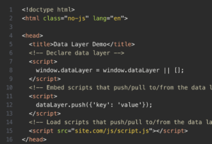
Photo credit: Makers Aid
An important note here is that the data layer declaration must come before any and all scripts that require a data push or pull from it. The script where you declare the data layer has to precede any third-party tools; this includes consent and tag managers. In other words, never reassign the data layer object . This action will delete all prior pushed data. This may disrupt the data as it moves to the application layer, creating inconsistencies.
Also, if you create multiple data layers, they need to be assigned different but uniform names. If you name the first one datalayer1, for instance, then follow the same formula by naming subsequent layers datalayer2, datalayer3, etc.
2. Create a data push
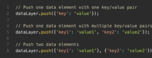
The next step is to create a data push to the data layer. The simplest method is to use JavaScript’s Array.push(). Furthermore, you can use the dataLayer.push() to push multiple data sets to the data layer. Be sure to distinguish nearby key and value pairs using a comma. Each data stream should also be surrounded by curly brackets. When implemented correctly, the data is incorporated into the array object end in the order you push them.
Here’s an example of creating a data push to the data layer:
3. Pull data
When pulling data from the data layer, you’ll most likely use a tag management system like Tealium or Google Tag Manager. From here, the data enters a downstream network where it’s absorbed by a suite of analytic and metric tools.
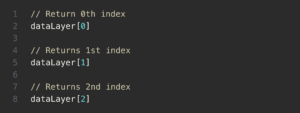
If you need to access data in the data layer, you can reference the array object’s name. Here’s an example of what this may look like for a data layer aptly named datalayer.
Simplify data layer implementation with Lytics
Try Lytic’s Cloud Connect today. Get 24/7 access to your data no matter where you’re at. Create efficient multi-layer data layers, produce data layer extensions, and completely eliminate data silos. Whether your team operates in-house or remotely, we make data layer implementation an intuitive process. Try Lytics risk-free for 30 days by signing up for a trial today.

Share this article
Get value straight to your inbox
Get the latest news, freshest insights, and newest product updates direct from Lytics experts.
We respect your information. Please see our privacy policy to learn more.
Recommended articles powered by Lytics

- Integrations
- Documentation
- Take a tour
- Deployment options
- Google preferred CDP
- Financial Services
- Media and Entertainment
- Retail + CPG
- Data analyst
- Marketing professional
- Optimize advertising spend
- Personalize email recommendations
- Personalize web experiences
- Product recommendations for commerce
- Build highly targeted audiences
- Customer stories
- White papers

Exploring the 3 layers of software interactions (APIs)

Application Programming Interfaces, commonly known as APIs, are a set of protocols, routines, and tools that enable software applications to interact with each other. They allow different software applications to exchange information seamlessly and efficiently.
APIs have become increasingly important in today's digital world, as they enable developers to build powerful applications that can connect with other services and platforms. APIs can be broken down into three different layers, each of which serves a different purpose.
In this blog post, we will explore the three layers of APIs and what they do.
1. Presentation Layer
The presentation layer, also known as the "API endpoint," is the layer that developers interact with most frequently. This layer provides a user-friendly interface for developers to access the functionality and data of the underlying service. It is responsible for processing incoming requests and returning responses in a format that developers can easily understand.
The presentation layer can take many different forms, depending on the requirements of the API. It could be a REST API that uses HTTP requests to exchange data or a SOAP API that uses XML messages to communicate. Regardless of the specific implementation, the presentation layer is the public-facing aspect of the API and is the first point of contact for developers.
2. Business Logic Layer
The business logic layer, also known as the "API middleware," is the layer that contains the core logic of the API. It is responsible for processing the requests received from the presentation layer and generating responses based on the requested actions.
The business logic layer is where the API's core functionality resides. It may perform data validation, authentication and authorization, database queries, or other complex operations. This layer is typically developed by the service provider and is not exposed directly to developers.
3. Data Storage Layer
The data storage layer, also known as the "API database," is the layer where all of the data used by the API is stored. This layer is responsible for managing data storage, retrieval, and modification. It may use a variety of database technologies such as SQL, NoSQL, or object-oriented databases.
The data storage layer is the most critical component of the API since it holds the data that the API relies on. If the data storage layer fails, the entire API may fail. Therefore, it is crucial to ensure that the data storage layer is designed and implemented correctly.
In conclusion, APIs consist of three layers: presentation layer, business logic layer, and data storage layer. Each layer plays a crucial role in the API's functionality and performance. Understanding the three layers of an API is essential for developers looking to build robust, reliable, and scalable APIs.
Related articles

What is Application Programming Interface (API)?
An API is a set of rules and practices that allow two applications to communicate. This means that one can use one application to retrieve data from another application or send data to another application.
NDepend Blog
Improve your .NET code quality with NDepend

Software Architecture: The 5 Patterns You Need to Know
Share this:.
When I was attending night school to become a programmer, I learned several design patterns : singleton, repository, factory, builder, decorator, etc. Design patterns give us a proven solution to existing and recurring problems. What I didn’t learn was that a similar mechanism exists on a higher level in the form of the software architecture pattern .
These are patterns for the overall layout of your application or applications. They all have advantages and disadvantages. And they all address specific issues.
In this post, we’ll take a look at 5 such patterns in detail. For each software architecture pattern, this will include a description, its advantages, its disadvantages, and the situation for which it is ideal. The patterns are as follows.
- The Layered Architectural Pattern
- The Microkernel Architectural Pattern
- The CQRS Architectural Pattern
- The Event Sourcing Architectural Pattern
- The Microservices Architectural Pattern
Download the NDepend trial for free and use dependency graphs to get a feel for what your software architecture really looks like.
1. The Layered Architectural Pattern
The layered pattern is probably one of the most well-known software architecture patterns.
Many developers use it, without really knowing its name. The idea is to split up your code into “layers”, where each layer has a certain responsibility and provides a service to a higher layer.
There isn’t a predefined number of layers, but these are the ones you see most often:
- Presentation or UI layer
- Application layer
- Business or domain layer
- Persistence or data access layer
- Database layer
The idea is that the user initiates a piece of code in the presentation layer by performing some action (e.g. clicking a button). The presentation layer then calls the underlying layer, i.e. the application layer.
Then we go into the business layer and finally, the persistence layer stores everything in the database. So higher layers are dependent upon and make calls to the lower layers.

You will see variations of this, depending on the complexity of the applications. Some applications might omit the application layer, while others add a caching layer.
It’s even possible to merge two layers into one. For example, the ActiveRecord pattern combines the business and persistence layers.
Layer Responsibility
As mentioned, each layer has its own responsibility.
The presentation layer contains the graphical design of the application, as well as any code to handle user interaction. You shouldn’t add logic that is not specific to the user interface in this layer.
The business layer is where you put the models and logic that is specific to the business problem you are trying to solve.
The application layer sits between the presentation layer and the business layer.
On the one hand, it provides an abstraction so that the presentation layer doesn’t need to know the business layer. In theory, you could change the technology stack of the presentation layer without changing anything else in your application (e.g. change from WinForms to WPF).
On the other hand, the application layer provides a place to put certain coordination logic that doesn’t fit in the business or presentation layer.

Finally, the persistence layer contains the code to access the database layer. The database layer is the underlying database technology (e.g. SQL Server, MongoDB). The persistence layer is the set of code to manipulate the database: SQL statements, connection details, etc.
- Most developers are familiar with this pattern.
- It provides an easy way of writing a well-organized and testable application .
Disadvantages
- It tends to lead to monolithic applications that are hard to split up afterward.
- Developers often find themselves writing a lot of code to pass through the different layers, without adding any value in these layers. If all you are doing is writing a simple CRUD application, the layered pattern might be overkill for you.
- Standard line-of-business apps that do more than just CRUD operations
2. The Microkernel Architectural Pattern
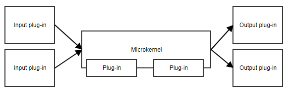
The microkernel pattern, or plug-in pattern, is useful when your application has a core set of responsibilities and a collection of interchangeable parts on the side. The microkernel will provide the entry point and the general flow of the application, without really knowing what the different plug-ins are doing.
An example is a task scheduler.
The microkernel could contain all the logic for scheduling and triggering tasks, while the plug-ins contain specific tasks. As long as the plug-ins adhere to a predefined API, the microkernel can trigger them without needing to know the implementation details.
Another example is a workflow. The implementation of a workflow contains concepts like the order of the different steps, evaluating the results of steps, deciding what the next step is, etc. The specific implementation of the steps is less important to the core code of the workflow.
- This pattern provides great flexibility and extensibility.
- Some implementations allow for adding plug-ins while the application is running.
- Microkernel and plug-ins can be developed by separate teams.
- It can be difficult to decide what belongs in the microkernel and what doesn’t.
- The predefined API might not be a good fit for future plug-ins.
- Applications that take data from different sources, transform that data and writes it to different destinations
- Workflow applications
- Task and job scheduling applications
3. The CQRS Architectural Pattern
CQRS is an acronym for Command and Query Responsibility Segregation . The central concept of this pattern is that an application has read operations and write operations that must be totally separated.
This also means that the model used for write operations (commands) will differ from the read models (queries). Furthermore, the data will be stored in different locations. In a relational database, this means there will be tables for the command model and tables for the read model. Some implementations even store the different models in totally different databases, e.g. SQL Server for the command model and MongoDB for the read model.
This pattern is often combined with event sourcing, which we’ll cover below.
How does it work exactly?
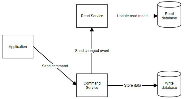
When the application needs to show data to the user, it can retrieve the read model by calling the read service, as shown below.
- Command models can focus on business logic and validation while read models can be tailored to specific scenarios.
- You can avoid complex queries (e.g. joins in SQL) which makes the reads more performant.
- Keeping the command and the read models in sync can become complex.
- Applications that expect a high amount of reads
- Applications with complex domains
4. The Event Sourcing Architectural Pattern
As I mentioned above, CQRS often goes hand in hand with event sourcing. This is a pattern where you don’t store the current state of your model in the database, but rather the events that happened to the model. So when the name of a customer changes, you won’t store the value in a “Name” column. You will store a “NameChanged” event with the new value (and possibly the old one too).
When you need to retrieve a model, you retrieve all its stored events and reapply them on a new object. We call this rehydrating an object.
A real-life analogy of event sourcing is accounting. When you add an expense, you don’t change the value of the total. In accounting, a new line is added with the operation to be performed.
If an error was made, you simply add a new line. To make your life easier, you could calculate the total every time you add a line. This total can be regarded as the read model. The example below should make it more clear.

You can see that we made an error when adding Invoice 201805. Instead of changing the line, we added two new lines: first, one to cancel the wrong line, then a new and correct line.
This is how event sourcing works. You never remove events, because they have undeniably happened in the past. To correct situations, we add new events.
Also, note how we have a cell with the total value. This is simply a sum of all values in the cells above. In Excel, it automatically updates so you could say it synchronizes with the other cells. It is the read model, providing an easy view for the user.
Event sourcing is often combined with CQRS because rehydrating an object can have a performance impact, especially when there are a lot of events for the instance. A fast read model can significantly improve the response time of the application.
- This software architecture pattern can provide an audit log out of the box. Each event represents a manipulation of the data at a certain point in time.
- It requires some discipline because you can’t just fix wrong data with a simple edit in the database.
- It’s not a trivial task to change the structure of an event. For example, if you add a property, the database still contains events without that data. Your code will need to handle this missing data graciously.
Ideal for Applications That:
- Need to publish events to external systems
- Will be built with CQRS
- Have complex domains
- Need an audit log of changes to the data
5. The Microservices Architectural Pattern
When you write your application as a set of microservices, you’re actually writing multiple applications that will work together. Each microservice has its own distinct responsibility and teams can develop them independently of other microservices.
The only dependency between them is the communication. As microservices communicate with each other, you will have to make sure messages sent between them remain backwards compatible. This requires some coordination, especially when different teams are responsible for different microservices.
A diagram can explain.
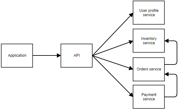
You can imagine this is an application where the user can order something. The separate microservices can call each other too. For example, the payment service may notify the orders service when a payment succeeds. The orders service could then call the inventory service to adjust the stock.
There is no clear rule of how big a microservice can be. In the previous example, the user profile service may be responsible for data like the username and password of a user, but also the home address, avatar image, favorites, etc. It could also be an option to split all those responsibilities into even smaller microservices.
- You can write, maintain, and deploy each microservice separately.
- A microservices architecture should be easier to scale, as you can scale only the microservices that need to be scaled. There’s no need to scale the less frequently used pieces of the application.
- It’s easier to rewrite pieces of the application because they’re smaller and less coupled to other parts.
- Contrary to what you might expect, it’s actually easier to write a well-structured monolith at first and split it up into microservices later. With microservices, a lot of extra concerns come into play: communication, coordination, backward compatibility, logging, etc. Teams that miss the necessary skill to write a well-structured monolith will probably have a hard time writing a good set of microservices.
- A single action of a user can pass through multiple microservices. There are more points of failure, and when something does go wrong, it can take more time to pinpoint the problem.
- Applications where certain parts will be used intensively and need to be scaled
- Services that provide functionality to several other applications
- Applications that would become very complex if combined into one monolith
- Applications where clear bounded contexts can be defined
I’ve explained several software architecture patterns, as well as their advantages and disadvantages. But there are more patterns than the ones I’ve laid out here. It is also not uncommon to combine several of these patterns.
They aren’t always mutually exclusive. For example, you could have several microservices and have some of them use the layered pattern, while others use CQRS and event sourcing.
The important thing to remember is that there isn’t one solution that works everywhere. When we ask the question of which pattern to use for an application, the age-old answer still applies: “it depends.”
You should weigh in on the pros and cons of a solution and make a well-informed decision.
Make your .NET code beautiful with NDepend
Download the NDepend Trial and gain valuable insights into your .NET code within a few minutes
- Pingback: Software Architecture: the 5 Patterns You Need to Know – NDepend – Bitbucket Bits
Nice article, Peter! These are great essentials that every developer should know about.
I like the clear structure of the article. What I’m missing is a suggestion on the architecture of the services of a microservice architecture.
could be added in this list the architecture of ports and adapters, the clean architecture or the onion
Simply fantastic with real-time examples
Comments are closed.
Flutter App Architecture: The Presentation Layer
Andrea Bizzotto
Updated Sep 21, 2023 11 min read
When writing Flutter apps, separating any business logic from the UI code is very important.
This makes our code more testable and easier to reason about , and is especially important as our apps become more complex.
To accomplish this, we can use design patterns to introduce a separation of concerns between different components in our app.
And for reference, we can adopt a layered app architecture such as the one represented in this diagram:
I have already covered some of the layers above in other articles:
- Flutter App Architecture with Riverpod: An Introduction
- Flutter App Architecture: The Repository Pattern
- Flutter App Architecture: The Domain Model
- Flutter App Architecture: The Application Layer
And this time, we will focus on the presentation layer and learn how we can use controllers to:
- hold business logic
- manage the widget state
- interact with repositories in the data layer
This kind of controller is the same as the view model that you would use in the MVVM pattern . If you've worked with flutter_bloc before, it has the same role as a cubit .
We will learn about the AsyncNotifier class, which is a replacement for the StateNotifier and the ValueNotifier / ChangeNotifier classes in the Flutter SDK.
And to make this more useful, we will implement a simple authentication flow as an example.
Ready? Let's go!
A simple authentication flow
Let's consider a very simple app that we can use to sign in anonymously and toggle between two screens:
And in this article, we'll focus on how to implement:
- an auth repository that we can use to sign in and sign out
- a sign-in widget screen that we show to the user
- the corresponding controller class that mediates between the two
Here's a simplified version of the reference architecture for this specific example:
You can find the complete source code for this app on GitHub . For more info about how it is organized, read this: Flutter Project Structure: Feature-first or Layer-first?
The AuthRepository class
As a starting point, we can define a simple abstract class that contains three methods that we'll use to sign in, sign out, and check the authentication state:
In practice, we also need a concrete class that implements AuthRepository . This could be based on Firebase or any other backend. We can even implement it with a fake repository for now. For more details, see this article about the repository pattern .
For completeness, we can also define a simple AppUser model class:
And if we use Riverpod, we also need a Provider that we can use to access our repository:
Next up, let's focus on the sign-in screen.
The SignInScreen widget
Suppose we have a simple SignInScreen widget defined like so:
This is just a simple Scaffold with an ElevatedButton in the middle.
Note that since this class extends ConsumerWidget , in the build() method we have an extra ref object that we can use to access providers as needed.
Accessing the AuthRepository directly from our widget
As a next step, we can use the onPressed callback to sign in like so:
This code works by obtaining the AuthRepository with a call to ref.read(authRepositoryProvider) . and calling the signInAnonymously() method on it.
This covers the happy path (sign-in successful). But we should also account for loading and error states by:
- disabling the sign-in button and showing a loading indicator while sign-in is in progress
- showing a SnackBar or alert if the call fails for any reason
The "StatefulWidget + setState" way
One simple way of addressing this is to:
- convert our widget into a StatefulWidget (or rather, ConsumerStatefulWidget since we're using Riverpod)
- add some local variables to keep track of state changes
- set those variables inside calls to setState() to trigger a widget rebuild
- use them to update the UI
Here's how the resulting code may look like:
For a simple app like this, this is probably ok.
But this approach gets quickly out of hand when we have more complex widgets, as we are mixing business logic and UI code in the same widget class.
And if we want to handle loading in error states consistently across multiple widgets, copy-pasting and tweaking the code above is quite error-prone (and not much fun).
Instead, it would be best to move all these concerns into a separate controller class that can:
- mediate between our SignInScreen and the AuthRepository
- provide a way for the widget to observe state changes and rebuild itself as a result
So let's see how to implement it in practice.
A controller class based on AsyncNotifier
The first step is to create a AsyncNotifier subclass which looks like this:
Or even better, we can use the new @riverpod syntax and let Riverpod Generator do the heavy lifting for us:
Either way, we need to implement a build method, which returns the initial value that should be used when the controller is first loaded.
If desired, we can use the build method to do some asynchronous initialization (such as loading some data from the network). But if the controller is "ready to go" as soon as it is created (just like in this case), we can leave the body empty and set the return type to Future<void> .
Implementing the method to sign in
Next up, let's add a method that we can use to sign in:
A few notes:
- We obtain the authRepository by calling ref.read on the corresponding provider ( ref is a property of the base AsyncNotifier class)
- Inside signInAnonymously() , we set the state to AsyncLoading so that the widget can show a loading UI
- Then, we call AsyncValue.guard and await for the result (which will be either AsyncData or AsyncError )
AsyncValue.guard is a handy alternative to try / catch . For more info, read this: Use AsyncValue.guard rather than try/catch inside your AsyncNotifier subclasses
And as an extra tip, we can use a method tear-off to simplify our code even further:
This completes the implementation of our controller class, in just a few lines of code:
Note about the relationship between types
Note that there is a clear relationship between the return type of the build method and the type of the state property:
In fact, using AsyncValue<void> as the state allows us to represent three possible values:
- default (not loading) as AsyncData (same as AsyncValue.data )
- loading as AsyncLoading (same as AsyncValue.loading )
- error as AsyncError (same as AsyncValue.error )
If you're not familiar with AsyncValue and its subclasses, read this: How to handle loading and error states with StateNotifier & AsyncValue in Flutter
Time to get back to our widget class and wire everything up!
Using our controller in the widget class
Here's an updated version of the SignInScreen that uses our new SignInScreenController class:
Note how in the build() method we watch our provider and rebuild the widget when the state changes.
And in the onPressed callback we read the provider's notifier and call signInAnonymously() . And we can also use the isLoading property to conditionally disable the button while sign-in is in progress.
We're almost done, and there's only one thing left to do.
Listening to state changes
Right at the top of the build method, we can add this:
We can use this code to call a listener callback whenever the state changes.
This is useful for showing an error alert or a SnackBar if an error occurs when signing in.
Bonus: An AsyncValue extension method
The listener code above is quite useful and we may want to reuse it in multiple widgets.
To do that, we can define this AsyncValue extension :
And then, in our widget, we can just import our extension and call this:
By implementing a custom controller class based on AsyncNotifier , we've separated our business logic from the UI code .
As a result, our widget class is now completely stateless and is only concerned with:
- watching state changes and rebuilding as a result (with ref.watch )
- responding to user input by calling methods in the controller (with ref.read )
- listening to state changes and showing errors if something goes wrong (with ref.listen )
Meanwhile, the job of our controller is to:
- talk to the repository on behalf of the widget
- emit state changes as needed
And since the controller doesn't depend on any UI code, it can be easily unit tested , and this makes it an ideal place to store any widget-specific business logic.
In summary, widgets and controllers belong to the presentation layer in our app architecture:
But there are three additional layers: data , domain , and application , and you can learn about them here:
Or if you want to dive deeper, check out my Flutter Foundations course. 👇
Flutter Foundations Course Now Available
I launched a brand new course that covers Flutter app architecture in great depth, along with other important topics like state management, navigation & routing, testing, and much more:

Flutter Foundations Course
Learn about State Management, App Architecture, Navigation, Testing, and much more by building a Flutter eCommerce app on iOS, Android, and web.
Invest in yourself with my high-quality Flutter courses.

Flutter & Firebase Masterclass
Learn about Firebase Auth, Cloud Firestore, Cloud Functions, Stripe payments, and much more by building a full-stack eCommerce app with Flutter & Firebase.

The Complete Dart Developer Guide
Learn Dart Programming in depth. Includes: basic to advanced topics, exercises, and projects. Fully updated to Dart 2.15.

Flutter Animations Masterclass
Master Flutter animations and build a completely custom habit tracking application.
Presentation Layer
- First Online: 13 June 2023
Cite this chapter

- Brian Hodel 2
424 Accesses
3 Altmetric
The presentation layer consists of various methods of presenting and interacting with your data. In Power Platform, there are several tools with which to do this, such as Power Apps, Power BI, and Power Pages. Designing an interface for your data is one of the more challenging aspects of designing a solution because it is where users interact with data. It needs to be built in such a way that users can intuitively find and navigate data structures. In my experience, this part of the process involves numerous iterations to find a balance between functionality and what makes sense to users.
This is a preview of subscription content, log in via an institution to check access.
Access this chapter
- Available as EPUB and PDF
- Read on any device
- Instant download
- Own it forever
- Compact, lightweight edition
- Dispatched in 3 to 5 business days
- Free shipping worldwide - see info
Tax calculation will be finalised at checkout
Purchases are for personal use only
Institutional subscriptions
Author information
Authors and affiliations.
Bothell, WA, USA
Brian Hodel
You can also search for this author in PubMed Google Scholar
Rights and permissions
Reprints and permissions
Copyright information
© 2023 The Author(s), under exclusive license to APress Media, LLC, part of Springer Nature
About this chapter
Hodel, B. (2023). Presentation Layer. In: Beginning Microsoft Dataverse. Apress, Berkeley, CA. https://doi.org/10.1007/978-1-4842-9334-8_5
Download citation
DOI : https://doi.org/10.1007/978-1-4842-9334-8_5
Published : 13 June 2023
Publisher Name : Apress, Berkeley, CA
Print ISBN : 978-1-4842-9333-1
Online ISBN : 978-1-4842-9334-8
eBook Packages : Professional and Applied Computing Apress Access Books Professional and Applied Computing (R0)
Share this chapter
Anyone you share the following link with will be able to read this content:
Sorry, a shareable link is not currently available for this article.
Provided by the Springer Nature SharedIt content-sharing initiative
- Publish with us
Policies and ethics
- Find a journal
- Track your research
This browser is no longer supported.
Upgrade to Microsoft Edge to take advantage of the latest features, security updates, and technical support.
Creating a Business Logic Layer (C#)
- 9 contributors
by Scott Mitchell
Download PDF
In this tutorial we'll see how to centralize your business rules into a Business Logic Layer (BLL) that serves as an intermediary for data exchange between the presentation layer and the DAL.
Introduction
The Data Access Layer (DAL) created in the first tutorial cleanly separates the data access logic from the presentation logic. However, while the DAL cleanly separates the data access details from the presentation layer, it does not enforce any business rules that may apply. For example, for our application we may want to disallow the CategoryID or SupplierID fields of the Products table to be modified when the Discontinued field is set to 1, or we might want to enforce seniority rules, prohibiting situations in which an employee is managed by someone who was hired after them. Another common scenario is authorization perhaps only users in a particular role can delete products or can change the UnitPrice value.
In this tutorial we'll see how to centralize these business rules into a Business Logic Layer (BLL) that serves as an intermediary for data exchange between the presentation layer and the DAL. In a real-world application, the BLL should be implemented as a separate Class Library project; however, for these tutorials we'll implement the BLL as a series of classes in our App_Code folder in order to simplify the project structure. Figure 1 illustrates the architectural relationships among the presentation layer, BLL, and DAL.

Figure 1 : The BLL Separates the Presentation Layer from the Data Access Layer and Imposes Business Rules
Step 1: Creating the BLL Classes
Our BLL will be composed of four classes, one for each TableAdapter in the DAL; each of these BLL classes will have methods for retrieving, inserting, updating, and deleting from the respective TableAdapter in the DAL, applying the appropriate business rules.
To more cleanly separate the DAL- and BLL-related classes, let's create two subfolders in the App_Code folder, DAL and BLL . Simply right-click on the App_Code folder in the Solution Explorer and choose New Folder. After creating these two folders, move the Typed DataSet created in the first tutorial into the DAL subfolder.
Next, create the four BLL class files in the BLL subfolder. To accomplish this, right-click on the BLL subfolder, choose Add a New Item, and choose the Class template. Name the four classes ProductsBLL , CategoriesBLL , SuppliersBLL , and EmployeesBLL .

Figure 2 : Add Four New Classes to the App_Code Folder
Next, let's add methods to each of the classes to simply wrap the methods defined for the TableAdapters from the first tutorial. For now, these methods will just call directly into the DAL; we'll return later to add any needed business logic.
If you are using Visual Studio Standard Edition or above (that is, you're not using Visual Web Developer), you can optionally design your classes visually using the Class Designer . Refer to the Class Designer Blog for more information on this new feature in Visual Studio.
For the ProductsBLL class we need to add a total of seven methods:
- GetProducts() returns all products
- GetProductByProductID(productID) returns the product with the specified product ID
- GetProductsByCategoryID(categoryID) returns all products from the specified category
- GetProductsBySupplier(supplierID) returns all products from the specified supplier
- AddProduct(productName, supplierID, categoryID, quantityPerUnit, unitPrice, unitsInStock, unitsOnOrder, reorderLevel, discontinued) inserts a new product into the database using the values passed-in; returns the ProductID value of the newly inserted record
- UpdateProduct(productName, supplierID, categoryID, quantityPerUnit, unitPrice, unitsInStock, unitsOnOrder, reorderLevel, discontinued, productID) updates an existing product in the database using the passed-in values; returns true if precisely one row was updated, false otherwise
- DeleteProduct(productID) deletes the specified product from the database
ProductsBLL.cs
The methods that simply return data GetProducts , GetProductByProductID , GetProductsByCategoryID , and GetProductBySuppliersID are fairly straightforward as they simply call down into the DAL. While in some scenarios there may be business rules that need to be implemented at this level (such as authorization rules based on the currently logged on user or the role to which the user belongs), we'll simply leave these methods as-is. For these methods, then, the BLL serves merely as a proxy through which the presentation layer accesses the underlying data from the Data Access Layer.
The AddProduct and UpdateProduct methods both take in as parameters the values for the various product fields and add a new product or update an existing one, respectively. Since many of the Product table's columns can accept NULL values ( CategoryID , SupplierID , and UnitPrice , to name a few), those input parameters for AddProduct and UpdateProduct that map to such columns use nullable types . Nullable types are new to .NET 2.0 and provide a technique for indicating whether a value type should, instead, be null . In C# you can flag a value type as a nullable type by adding ? after the type (like int? x; ). Refer to the Nullable Types section in the C# Programming Guide for more information.
All three methods return a Boolean value indicating whether a row was inserted, updated, or deleted since the operation may not result in an affected row. For example, if the page developer calls DeleteProduct passing in a ProductID for a non-existent product, the DELETE statement issued to the database will have no affect and therefore the DeleteProduct method will return false .
Note that when adding a new product or updating an existing one we take in the new or modified product's field values as a list of scalars as opposed to accepting a ProductsRow instance. This approach was chosen because the ProductsRow class derives from the ADO.NET DataRow class, which doesn't have a default parameterless constructor. In order to create a new ProductsRow instance, we must first create a ProductsDataTable instance and then invoke its NewProductRow() method (which we do in AddProduct ). This shortcoming rears its head when we turn to inserting and updating products using the ObjectDataSource. In short, the ObjectDataSource will try to create an instance of the input parameters. If the BLL method expects a ProductsRow instance, the ObjectDataSource will try to create one, but fail due to the lack of a default parameterless constructor. For more information on this problem, refer to the following two ASP.NET Forums posts: Updating ObjectDataSources with Strongly-Typed DataSets , and Problem With ObjectDataSource and Strongly-Typed DataSet .
Next, in both AddProduct and UpdateProduct , the code creates a ProductsRow instance and populates it with the values just passed in. When assigning values to DataColumns of a DataRow various field-level validation checks can occur. Therefore, manually putting the passed in values back into a DataRow helps ensure the validity of the data being passed to the BLL method. Unfortunately the strongly-typed DataRow classes generated by Visual Studio do not use nullable types. Rather, to indicate that a particular DataColumn in a DataRow should correspond to a NULL database value we must use the SetColumnNameNull() method.
In UpdateProduct we first load in the product to update using GetProductByProductID(productID) . While this may seem like an unnecessary trip to the database, this extra trip will prove worthwhile in future tutorials that explore optimistic concurrency. Optimistic concurrency is a technique to ensure that two users who are simultaneously working on the same data don't accidentally overwrite one another's changes. Grabbing the entire record also makes it easier to create update methods in the BLL that only modify a subset of the DataRow's columns. When we explore the SuppliersBLL class we'll see such an example.
Finally, note that the ProductsBLL class has the DataObject attribute applied to it (the [System.ComponentModel.DataObject] syntax right before the class statement near the top of the file) and the methods have DataObjectMethodAttribute attributes . The DataObject attribute marks the class as being an object suitable for binding to an ObjectDataSource control , whereas the DataObjectMethodAttribute indicates the purpose of the method. As we'll see in future tutorials, ASP.NET 2.0's ObjectDataSource makes it easy to declaratively access data from a class. To help filter the list of possible classes to bind to in the ObjectDataSource's wizard, by default only those classes marked as DataObjects are shown in the wizard's drop-down list. The ProductsBLL class will work just as well without these attributes, but adding them makes it easier to work with in the ObjectDataSource's wizard.
Adding the Other Classes
With the ProductsBLL class complete, we still need to add the classes for working with categories, suppliers, and employees. Take a moment to create the following classes and methods using the concepts from the example above:
CategoriesBLL.cs
- GetCategories()
- GetCategoryByCategoryID(categoryID)
SuppliersBLL.cs
- GetSuppliers()
- GetSupplierBySupplierID(supplierID)
- GetSuppliersByCountry(country)
- UpdateSupplierAddress(supplierID, address, city, country)
EmployeesBLL.cs
- GetEmployees()
- GetEmployeeByEmployeeID(employeeID)
- GetEmployeesByManager(managerID)
The one method worth noting is the SuppliersBLL class's UpdateSupplierAddress method. This method provides an interface for updating just the supplier's address information. Internally, this method reads in the SupplierDataRow object for the specified supplierID (using GetSupplierBySupplierID ), sets its address-related properties, and then calls down into the SupplierDataTable 's Update method. The UpdateSupplierAddress method follows:
Refer to this article's download for my complete implementation of the BLL classes.
Step 2: Accessing the Typed DataSets Through the BLL Classes
In the first tutorial we saw examples of working directly with the Typed DataSet programmatically, but with the addition of our BLL classes, the presentation tier should work against the BLL instead. In the AllProducts.aspx example from the first tutorial, the ProductsTableAdapter was used to bind the list of products to a GridView, as shown in the following code:
To use the new BLL classes, all that needs to be changed is the first line of code simply replace the ProductsTableAdapter object with a ProductBLL object:
The BLL classes can also be accessed declaratively (as can the Typed DataSet) by using the ObjectDataSource. We'll be discussing the ObjectDataSource in greater detail in the following tutorials.

Figure 3 : The List of Products is Displayed in a GridView ( Click to view full-size image )
Step 3: Adding Field-Level Validation to the DataRow Classes
Field-level validation are checks that pertains to the property values of the business objects when inserting or updating. Some field-level validation rules for products include:
- The ProductName field must be 40 characters or less in length
- The QuantityPerUnit field must be 20 characters or less in length
- The ProductID , ProductName , and Discontinued fields are required, but all other fields are optional
- The UnitPrice , UnitsInStock , UnitsOnOrder , and ReorderLevel fields must be greater than or equal to zero
These rules can and should be expressed at the database level. The character limit on the ProductName and QuantityPerUnit fields are captured by the data types of those columns in the Products table ( nvarchar(40) and nvarchar(20) , respectively). Whether fields are required and optional are expressed by if the database table column allows NULL s. Four check constraints exist that ensure that only values greater than or equal to zero can make it into the UnitPrice , UnitsInStock , UnitsOnOrder , or ReorderLevel columns.
In addition to enforcing these rules at the database they should also be enforced at the DataSet level. In fact, the field length and whether a value is required or optional are already captured for each DataTable's set of DataColumns. To see the existing field-level validation automatically provided, go to the DataSet Designer, select a field from one of the DataTables and then go to the Properties window. As Figure 4 shows, the QuantityPerUnit DataColumn in the ProductsDataTable has a maximum length of 20 characters and does allow NULL values. If we attempt to set the ProductsDataRow 's QuantityPerUnit property to a string value longer than 20 characters an ArgumentException will be thrown.

Figure 4 : The DataColumn Provides Basic Field-Level Validation ( Click to view full-size image )
Unfortunately, we can't specify bounds checks, such as the UnitPrice value must be greater than or equal to zero, through the Properties window. In order to provide this type of field-level validation we need to create an event handler for the DataTable's ColumnChanging event. As mentioned in the preceding tutorial , the DataSet, DataTables, and DataRow objects created by the Typed DataSet can be extended through the use of partial classes. Using this technique we can create a ColumnChanging event handler for the ProductsDataTable class. Start by creating a class in the App_Code folder named ProductsDataTable.ColumnChanging.cs .

Figure 5 : Add a New Class to the App_Code Folder ( Click to view full-size image )
Next, create an event handler for the ColumnChanging event that ensures that the UnitPrice , UnitsInStock , UnitsOnOrder , and ReorderLevel column values (if not NULL ) are greater than or equal to zero. If any such column is out of range, throw an ArgumentException .
ProductsDataTable.ColumnChanging.cs
Step 4: Adding Custom Business Rules to the BLL's Classes
In addition to field-level validation, there may be high-level custom business rules that involve different entities or concepts not expressible at the single column level, such as:
- If a product is discontinued, its UnitPrice cannot be updated
- An employee's country of residence must be the same as their manager's country of residence
- A product cannot be discontinued if it is the only product provided by the supplier
The BLL classes should contain checks to ensure adherence to the application's business rules. These checks can be added directly to the methods to which they apply.
Imagine that our business rules dictate that a product could not be marked discontinued if it was the only product from a given supplier. That is, if product X was the only product we purchased from supplier Y , we could not mark X as discontinued; if, however, supplier Y supplied us with three products, A , B , and C , then we could mark any and all of these as discontinued. An odd business rule, but business rules and common sense aren't always aligned!
To enforce this business rule in the UpdateProducts method we'd start by checking if Discontinued was set to true and, if so, we'd call GetProductsBySupplierID to determine how many products we purchased from this product's supplier. If only one product is purchased from this supplier, we throw an ApplicationException .
Responding to Validation Errors in the Presentation Tier
When calling the BLL from the presentation tier we can decide whether to attempt to handle any exceptions that might be raised or let them bubble up to ASP.NET (which will raise the HttpApplication 's Error event). To handle an exception when working with the BLL programmatically, we can use a try...catch block, as the following example shows:
As we'll see in future tutorials, handling exceptions that bubble up from the BLL when using a data Web control for inserting, updating, or deleting data can be handled directly in an event handler as opposed to having to wrap code in try...catch blocks.
A well architected application is crafted into distinct layers, each of which encapsulates a particular role. In the first tutorial of this article series we created a Data Access Layer using Typed DataSets; in this tutorial we built a Business Logic Layer as a series of classes in our application's App_Code folder that call down into our DAL. The BLL implements the field-level and business-level logic for our application. In addition to creating a separate BLL, as we did in this tutorial, another option is to extend the TableAdapters' methods through the use of partial classes. However, using this technique does not allow us to override existing methods nor does it separate our DAL and our BLL as cleanly as the approach we've taken in this article.
With the DAL and BLL complete, we're ready to start on our presentation layer. In the next tutorial we'll take a brief detour from data access topics and define a consistent page layout for use throughout the tutorials.
Happy Programming!
About the Author
Scott Mitchell, author of seven ASP/ASP.NET books and founder of 4GuysFromRolla.com , has been working with Microsoft Web technologies since 1998. Scott works as an independent consultant, trainer, and writer. His latest book is Sams Teach Yourself ASP.NET 2.0 in 24 Hours . He can be reached at [email protected]. or via his blog, which can be found at http://ScottOnWriting.NET .
Special Thanks To
This tutorial series was reviewed by many helpful reviewers. Lead reviewers for this tutorial were Liz Shulok, Dennis Patterson, Carlos Santos, and Hilton Giesenow. Interested in reviewing my upcoming MSDN articles? If so, drop me a line at [email protected].
Previous Next
Was this page helpful?
Coming soon: Throughout 2024 we will be phasing out GitHub Issues as the feedback mechanism for content and replacing it with a new feedback system. For more information see: https://aka.ms/ContentUserFeedback .
Submit and view feedback for
Additional resources
Oracle® Fusion Middleware
Data Modeling Guide for Oracle Business Intelligence Publisher
12c (12.2.1.4.0)
August 2021
Documentation for the individual responsible for modeling data sources used in building an Oracle Business Intelligence metadata repository, setting up and connecting to data sources, and building the Physical layer, Business Model and Mapping layer, and Presentation layer. Includes how to use the multiuser development environment.
Oracle Fusion Middleware Data Modeling Guide for Oracle Business Intelligence Publisher, 12c (12.2.1.4.0)
Copyright © 2015, 2021, Oracle and/or its affiliates.
Primary Author: Hemala Vivek
Contributing Author: Christine Jacobs, Suzanne Gill
Contributor: Oracle Business Intelligence Publisher development, quality assurance, and product management teams.
This software and related documentation are provided under a license agreement containing restrictions on use and disclosure and are protected by intellectual property laws. Except as expressly permitted in your license agreement or allowed by law, you may not use, copy, reproduce, translate, broadcast, modify, license, transmit, distribute, exhibit, perform, publish, or display any part, in any form, or by any means. Reverse engineering, disassembly, or decompilation of this software, unless required by law for interoperability, is prohibited.
The information contained herein is subject to change without notice and is not warranted to be error-free. If you find any errors, please report them to us in writing.
If this is software or related documentation that is delivered to the U.S. Government or anyone licensing it on behalf of the U.S. Government, then the following notice is applicable:
U.S. GOVERNMENT END USERS: Oracle programs (including any operating system, integrated software, any programs embedded, installed or activated on delivered hardware, and modifications of such programs) and Oracle computer documentation or other Oracle data delivered to or accessed by U.S. Government end users are "commercial computer software" or "commercial computer software documentation" pursuant to the applicable Federal Acquisition Regulation and agency-specific supplemental regulations. As such, the use, reproduction, duplication, release, display, disclosure, modification, preparation of derivative works, and/or adaptation of i) Oracle programs (including any operating system, integrated software, any programs embedded, installed or activated on delivered hardware, and modifications of such programs), ii) Oracle computer documentation and/or iii) other Oracle data, is subject to the rights and limitations specified in the license contained in the applicable contract. The terms governing the U.S. Government’s use of Oracle cloud services are defined by the applicable contract for such services. No other rights are granted to the U.S. Government.
This software or hardware is developed for general use in a variety of information management applications. It is not developed or intended for use in any inherently dangerous applications, including applications that may create a risk of personal injury. If you use this software or hardware in dangerous applications, then you shall be responsible to take all appropriate fail-safe, backup, redundancy, and other measures to ensure its safe use. Oracle Corporation and its affiliates disclaim any liability for any damages caused by use of this software or hardware in dangerous applications.
Oracle, Java, and MySQL are registered trademarks of Oracle and/or its affiliates. Other names may be trademarks of their respective owners.
Intel and Intel Inside are trademarks or registered trademarks of Intel Corporation. All SPARC trademarks are used under license and are trademarks or registered trademarks of SPARC International, Inc. AMD, Epyc, and the AMD logo are trademarks or registered trademarks of Advanced Micro Devices. UNIX is a registered trademark of The Open Group.
This software or hardware and documentation may provide access to or information about content, products, and services from third parties. Oracle Corporation and its affiliates are not responsible for and expressly disclaim all warranties of any kind with respect to third-party content, products, and services unless otherwise set forth in an applicable agreement between you and Oracle. Oracle Corporation and its affiliates will not be responsible for any loss, costs, or damages incurred due to your access to or use of third-party content, products, or services, except as set forth in an applicable agreement between you and Oracle.
Scripting on this page enhances content navigation, but does not change the content in any way.
- Help center
- Chinese (traditional)
Learn more
- Case Study
- Knowledge Center
- Glossary
Getting Started (119)
Product Updates (117)
News & Announcements (40)
Self Service (10)
Troubleshooting Guide (6)
Client Reviews (5)
Configuration Guide (5)
Product Testing (4)
Installation Guide (3)
Hear It from Experts (1)
Optics and Transceivers (97)
Switches (97)
Networking Devices (62)
Network Cabling and Wiring (59)
Optical Networking (18)
Networking (84)
Fiber Optic Communication (53)
Data Center (30)
General (26)
Wireless and Mobility (8)
Business Type (6)
Routing and Switching (5)
United Kingdom (1)
- Product Updates
- Networking Devices
- Case Study
- Knowledge Center

What is SD-WAN?
SD-WAN is an automated and programmatic method for managing enterprise network connectivity and circuit expenses. It expands the concept of software-defined networking (SDN) into a practical application that enables businesses to efficiently establish a sophisticated hybrid WAN.
Comprising business-grade IP VPN, broadband Internet, and wireless services, SD-WAN empowers you to efficiently oversee applications, especially those in the cloud, in a cost-effective manner. Traffic is automatically and dynamically directed through the optimal and most efficient WAN path, taking into account network conditions, application traffic security, quality-of-service (QoS) demands, and circuit costs. Routing policies can be configured according to your preferences.
SD-WAN in Industry Standards
Different SD-WAN vendors provide different definitions for SD-WAN. The following are typical industry definitions of SD-WAN.
SD-WAN Defined by Gartner
Gartner clearly defines the following basic features of SD-WAN:
1. Supports connections through hybrid links (including MPLS, Internet, and LTE links).
2. Supports dynamic path adjustment for load balancing of traffic across WAN connections.
3. Simplifies management and service provisioning, and enables zero touch provisioning (ZTP) of branch networks as easy as home Wi-Fi networks.
4. Supports virtual private networks (VPNs) and other value-added services (VASs), such as WAN optimization controllers (WOCs) and firewalls.
SD-WAN Defined by the MEF
The Metro Ethernet Forum (MEF) standardizes SD-WAN to MEF 70 (the first SD-WAN service standard). MEF 70 clearly defines SD-WAN components and capabilities, and defines the framework and application programming interface (API) service specifications for all interfaces of each component.
SD-WAN Benefits
Due to the comprehensive financial and operational benefits, enterprises are rapidly adopting SD-WAN technology. Key advantages include:
1. Lowers WAN OpEx, CapEx, and overall total cost of ownership.
2. Improving application performance and increasing agility.
3. Enables the use of several secure, high-performance connections, removing the backhaul penalties enforced by MPLS networks.
4. Enhances efficiency by distributing traffic across multiple connections and recalibrating data paths according to the state of the network.
5. Facilitates the automatic set-up and adjustment of advanced network functionalities, including Virtual Private Networks, firewalls, protection measures, Wide Area Network acceleration, and management of application traffic.
6. Supports Zero-Touch Provisioning (ZTP).
7. Bolsters network defenses by implementing WAN encryption and creating distinct network segments to contain the impact of any security compromises.
What are the Layers and Components of the SD-WAN Logical Architecture?
Viewed in terms of logical layers and functionalities, the SD-WAN logical architecture encompasses the service presentation layer, management layer, control layer, and network layer. Each layer serves distinct functions and comprises numerous core components, as delineated in the accompanying illustration.

Service Presentation Layer
The service presentation layer establishes a connection with a network controller in the southbound direction, enabling the implementation of SD-WAN service presentation and provisioning through service portals. This layer offers:
Proprietary portal: The SD-WAN solution provider offers a portal that allows customers to conduct end-to-end SD-WAN service configuration and management.
Third-party BSS/OSS: Third parties can utilize the northbound open APIs of the network controller to integrate the SD-WAN Solution and customize the GUI according to service functions and GUI layout requirements.
Management Layer
The network controller serves as the central component of the management layer, acting as the "smart brain" of the entire SD-WAN solution. It offers network orchestration and management functions:
Network orchestration: The network controller abstracts service-oriented SD-WAN network models, orchestrates enterprise WAN networking services, and enforces network policies. It automates service provisioning by defining enterprise WAN network models, shielding technical intricacies of SD-WAN deployment, and simplifying WAN configuration and service provisioning.
Network management: Within the network controller's management component, network management and operations functions are implemented for enterprise WANs. This includes tasks such as fault information collection (e.g., alarms, NE logs), performance data collection, statistics, and analysis based on links, applications, and networks. It also involves gathering and displaying multi-dimensional O&M information, including network topologies, alarms, and performance data.
Control Layer
The route reflector (RR) serves as a fundamental component within the control layer, tasked with network control responsibilities. It undertakes tasks such as distributing and filtering VPN routes for SD-WAN tenants, as well as creating and modifying VPN topologies. Additionally, the RR is responsible for establishing and maintaining overlay tunnels between sites.
In contrast to the distributed control mode found in traditional networks, this centralized control mode segregates the control plane from the forwarding plane of enterprise WANs. This approach streamlines network O&M operations, diminishes network configuration errors, and enhances the operational efficiency of enterprise WANs.
Network Layer
From a service standpoint, enterprise sites encompass branches, headquarters, data centers, and IT infrastructures deployed in the cloud. The SD-WAN network layer comprises network devices employed for WAN interconnection at various enterprise sites, along with the intermediate WAN infrastructure.
SD-WAN network devices include edge devices and gateways.
Edge devices
Edge devices are egress Customer Premises Equipment (CPEs) located at various enterprise sites including headquarters, branches, data centers, or cloud locations. They serve as the starting or ending points of SD-WAN tunnels and also act as border sites within the SD-WAN network. Overlay tunnels between edge devices can utilize any wired or wireless underlay WAN links and typically employ data encryption technologies such as IPsec to ensure the security of enterprise WAN data transmission.
Typically, both traditional hardware-based CPEs or universal (uCPEs) and virtual CPEs (vCPEs) can serve as edge devices in the SD-WAN Solution.
CPE: A traditional hardware CPE, initially deployed as a hardware device at a site, typically comprises a switching and routing unit (SRU), interface cards, multi-core CPUs, and various hardware components. Functioning at both hardware and software levels, a CPE provides Layer 2 switching and Layer 3 routing functions to connect internal and external networks at sites. This type of CPE is commonly referred to as a traditional CPE.
uCPE: With the emergence of cloud computing and Network Functions Virtualization (NFV) technologies, cloudification and virtualization have become inevitable trends. Functions traditionally offered by dedicated hardware devices can now be realized through software. For instance, security, WAN acceleration, and load balancing functions can be delivered through virtual network functions (VNFs). Integrating these functions into CPEs can lower device costs, reduce power consumption, and enable flexible and rapid service provisioning.
vCPE: When network functions typically performed by traditional CPEs are instead implemented through software, the software is decoupled from the hardware. These CPEs are known as vCPEs. vCPEs can replace dedicated hardware devices, executing the functions of traditional CPEs through software. This facilitates swift service deployment, enhances service scalability and flexibility, and decreases deployment and operational expenses.
An SD-WAN gateway serves as an intermediary device linking newly established SD-WAN sites with legacy VPN sites within an enterprise. With legacy non-SD-WAN sites still in operation, gateways are deployed to facilitate connectivity between SD-WAN networks and the traditional branch networks of enterprises.
SD-WAN Uses and Functions
The SD-WAN software that runs on the customer premises equipment (CPE) monitors the health of all the public and private line services and determines how each type of application traffic should be routed. For example, voice-over-IP (VoIP) traffic might default to an MPLS VPN service. However, if the MPLS connection becomes congested, the SD-WAN can redirect that traffic to a broadband Internet or 4G LTE wireless circuit. In this way, SD-WAN enables automatic load balancing and network congestion management for the best performance and most cost-effective routing.
You might be interested in

Email Address
Please enter your email address.
Please make sure you agree to our Privacy Policy and Terms of Use.

Cloud-based Networks Grow with Your Business

Anchor Your Hybrid Cloud Networking Strategy
- Network Cabling and Wiring
- Buying Guide
- Fiber Optic Communication
- Optics and Transceivers
- Data Center
- Ethernet Patch Cords
- Business Type
- Routing and Switching
- Optical Networking
- Best Practices
- 10G Network
- Home Networking

Fiber Optic Cable Types: Single Mode vs Multimode Fiber Cable
May 10, 2022

Layer 2 vs Layer 3 Switch: Which One Do You Need?
Oct 6, 2021

Multimode Fiber Types: OM1 vs OM2 vs OM3 vs OM4 vs OM5
Sep 22, 2021

Running 10GBASE-T Over Cat6 vs Cat6a vs Cat7 Cabling?
Mar 18, 2024

PoE vs PoE+ vs PoE++ Switch: How to Choose?
Mar 16, 2023
IMAGES
VIDEO
COMMENTS
The presentation tier and the data tier cannot communicate directly with one another. Tier versus layer. In discussions of three-tier architecture, layer is often used interchangeably - and mistakenly - for tier, as in 'presentation layer' or 'business logic layer'. They aren't the same.
The presentation layer should only be concerned about presenting data, not about how to retrieve it. Suppose you move your whole database into CSV files (I know, crazy idea), then your presentation layer should not be aware of this at all. So ideally, you have a business layer method that returns just the data you want to show to the user.
Architectural Overview - Presentation, Business Logic and Data Access layers. An application system consists of three logical layers. The presentation layer is what a system user sees or interacts with. It can consist of visual objects such as screens, web pages or reports or non-visual objects such as an interactive voice response interface.
Here are five main layers in software architecture: 1. Presentation layer. The presentation layer, also called the UI layer, handles the interactions that users have with the software. It's the most visible layer and defines the application's overall look and presentation to the end-users.
The Business-Logic Layer (BLL) is a component of a software architecture that is responsible for implementing the business logic of an application. It sits between the presentation layer (e.g., the user interface) and the data access layer (e.g., the database), and is responsible for processing and manipulating data before it is presented to ...
Assuming that the contracts (e.g., model) used between the presentation layer and the business layer remain the same, the business layer is not affected by the refactoring and remains completely independent of the type of user-interface framework used by the presentation layer. While closed layers facilitate layers of isolation and therefore ...
web development. One of the most common ways to modularize an information-rich program is to separate it into three broad layers: presentation (UI), domain logic (aka business logic), and data access. So you often see web applications divided into a web layer that knows about handling HTTP requests and rendering HTML, a business logic layer ...
Business Layer: Also known as the Logic Layer, it contains the business logic and rules that govern the application's behavior. This layer processes data from the presentation layer and ...
In the classic three tier design, applications break down into three major areas of functionality: The data layer manages the physical storage and retrieval of data. The business layer maintains business rules and logic. The presentation layer houses the user interface and related presentation code. Inside each of these tiers there may also ...
2. Create a data push. The next step is to create a data push to the data layer. The simplest method is to use JavaScript's Array.push (). Furthermore, you can use the dataLayer.push () to push multiple data sets to the data layer. Be sure to distinguish nearby key and value pairs using a comma.
The data storage layer is the most critical component of the API since it holds the data that the API relies on. If the data storage layer fails, the entire API may fail. Therefore, it is crucial to ensure that the data storage layer is designed and implemented correctly. In conclusion, APIs consist of three layers: presentation layer, business ...
Business or domain layer; Persistence or data access layer; Database layer; The idea is that the user initiates a piece of code in the presentation layer by performing some action (e.g. clicking a button). The presentation layer then calls the underlying layer, i.e. the application layer. Then we go into the business layer and finally, the ...
Prerequisite : OSI Model. Introduction : Presentation Layer is the 6th layer in the Open System Interconnection (OSI) model. This layer is also known as Translation layer, as this layer serves as a data translator for the network. The data which this layer receives from the Application Layer is extracted and manipulated here as per the required ...
The presentation layer is located at Layer 6 of the OSI model. The tool that manages Hypertext Transfer Protocol ( HTTP) is an example of a program that loosely adheres to the presentation layer of OSI. Although it's technically considered an application-layer protocol per the TCP/IP model, HTTP includes presentation layer services within it.
Flutter App Architecture: The Domain Model. Flutter App Architecture: The Application Layer. And this time, we will focus on the presentation layer and learn how we can use controllers to: hold business logic. manage the widget state. interact with repositories in the data layer. This kind of controller is the same as the view model that you ...
The presentation layer ensures the information that the application layer of one system sends out is readable by the application layer of another system. On the sending system it is responsible for conversion to standard, transmittable formats. [7] On the receiving system it is responsible for the translation, formatting, and delivery of ...
Data Access Layer (DAL). This layer is separated into two: DAL abstractions and DAL. The data access layer is the layer that implements the communication with the data source (usually a database).
Abstract. The presentation layer consists of various methods of presenting and interacting with your data. In Power Platform, there are several tools with which to do this, such as Power Apps, Power BI, and Power Pages. Designing an interface for your data is one of the more challenging aspects of designing a solution because it is where users ...
In this tutorial we'll see how to centralize your business rules into a Business Logic Layer (BLL) that serves as an intermediary for data exchange between the presentation layer and the DAL. Introduction. The Data Access Layer (DAL) created in the first tutorial cleanly separates the data access logic from the presentation logic. However ...
It's the presentation layer that knows to put the right information into the appropriate fields of a customer record, for example: Name, Date of Birth, Address, etc. The presentation layer is where you'll find the code for making a program look nice as well. Most importantly to this discussion, the presentation layer is where RPA functions.
Documentation for the individual responsible for modeling data sources used in building an Oracle Business Intelligence metadata repository, setting up and connecting to data sources, and building the Physical layer, Business Model and Mapping layer, and Presentation layer. Includes how to use the multiuser development environment.
Layers. The "Layers" architectural pattern has been described in various publications. Common layers. In a logical multilayer architecture for an information system with an object-oriented design, the following four are the most common: . Presentation layer (a.k.a. UI layer, view layer, presentation tier in multitier architecture); Application layer (a.k.a. service layer or GRASP Controller ...
It covers what you are asking here. The file with .aspx extension in your case is responsible for rendering a view. So it's categorized as a presentation layer. The second one with .cs extension is looking like it's trying to access the database. So it could be categorized as a data access layer. The business layer make use of your data access ...
Viewed in terms of logical layers and functionalities, the SD-WAN logical architecture encompasses the service presentation layer, management layer, control layer, and network layer. Each layer serves distinct functions and comprises numerous core components, as delineated in the accompanying illustration. Service Presentation Layer