- Sign in / Register
- Administration
- Edit profile

The PhET website does not support your browser. We recommend using the latest version of Chrome, Firefox, Safari, or Edge.

What Is Electronegativity and How Does It Work?
ThoughtCo/Todd Helmenstine
- Chemical Laws
- Periodic Table
- Projects & Experiments
- Scientific Method
- Biochemistry
- Physical Chemistry
- Medical Chemistry
- Chemistry In Everyday Life
- Famous Chemists
- Activities for Kids
- Abbreviations & Acronyms
- Weather & Climate
- Ph.D., Biomedical Sciences, University of Tennessee at Knoxville
- B.A., Physics and Mathematics, Hastings College
Electronegativity is the property of an atom which increases with its tendency to attract the electrons of a bond. If two bonded atoms have the same electronegativity values as each other, they share electrons equally in a covalent bond. Usually, the electrons in a chemical bond are more attracted to one atom (the more electronegative one) than to the other. This results in a polar covalent bond. If the electronegativity values are very different, the electrons aren't shared at all. One atom essentially takes the bond electrons from the other atom, forming an ionic bond.
Key Takeaways: Electronegativity
- Electronegativity is an atom's tendency to attract electrons to itself in a chemical bond.
- The most electronegative element is fluorine. The least electronegative or most electropositive element is francium.
- The greater the difference between atom electronegativity values, the more polar the chemical bond formed between them.
Avogadro and other chemists studied electronegativity before it was formally named by Jöns Jacob Berzelius in 1811. In 1932, Linus Pauling proposed an electronegativity scale based on bond energies. Electronegativity values on the Pauling scale are dimensionless numbers that run from about 0.7 to 3.98. The Pauling scale values are relative to the electronegativity of hydrogen (2.20). While the Pauling scale is most often used, other scales include the Mulliken scale, Allred-Rochow scale, Allen scale, and Sanderson scale.
Electronegativity is a property of an atom within a molecule, rather than an inherent property of an atom by itself. Thus, electronegativity actually varies depending on an atom's environment. However, most of the time an atom displays similar behavior in different situations. Factors that affect electronegativity include the nuclear charge and the number and location of electrons in an atom.
Electronegativity Example
The chlorine atom has a higher electronegativity than the hydrogen atom, so the bonding electrons will be closer to the Cl than to the H in the HCl molecule.
In the O 2 molecule, both atoms have the same electronegativity. The electrons in the covalent bond are shared equally between the two oxygen atoms.
Most and Least Electronegative Elements
The most electronegative element on the periodic table is fluorine (3.98). The least electronegative element is cesium (0.79). The opposite of electronegativity is electropositivity, so you could simply say cesium is the most electropositive element. Note that older texts list both francium and cesium as least electronegative at 0.7, but the value for cesium was experimentally revised to the 0.79 value. There is no experimental data for francium, but its ionization energy is higher than that of cesium, so it is expected that francium is slightly more electronegative.
Electronegativity as a Periodic Table Trend
Like electron affinity, atomic/ionic radius, and ionization energy, electronegativity shows a definite trend on the periodic table .
- Electronegativity generally increases moving from left to right across a period. The noble gases tend to be exceptions to this trend.
- Electronegativity generally decreases moving down a periodic table group. This correlates with the increased distance between the nucleus and the valence electron.
Electronegativity and ionization energy follow the same periodic table trend. Elements that have low ionization energies tend to have low electronegativities. The nuclei of these atoms don't exert a strong pull on electrons . Similarly, elements that have high ionization energies tend to have high electronegativity values. The atomic nucleus exerts a strong pull on electrons.
Jensen, William B. "Electronegativity from Avogadro to Pauling: Part 1: Origins of the Electronegativity Concept." 1996, 73, 1. 11, J. Chem. Educ., ACS Publications, January 1, 1996.
Greenwood, N. N. "Chemistry of the Elements." A. Earnshaw, (1984). 2nd Edition, Butterworth-Heinemann, December 9, 1997.
Pauling, Linus. "The Nature of the Chemical Bond. IV. The Energy of Single Bonds and the Relative Electronegativity of Atoms". 1932, 54, 9, 3570-3582, J. Am. Chem. Soc., ACS Publications, September 1, 1932.
Pauling, Linus. "The Nature of the Chemical Bond and the Structure of Molecules and Crystals: An Introduction to Mode." 3rd Edition, Cornell University Press, January 31, 1960.
- How to Use a Periodic Table of Elements
- Periodic Table Definition in Chemistry
- Printable Periodic Tables (PDF)
- Electronegativity and Chemical Bonding
- What Is the Most Electronegative Element?
- Learn Which Element Has the Lowest Electronegativity Value
- The Periodic Properties of the Elements
- Most Reactive Metal on the Periodic Table
- Why Do Atoms Create Chemical Bonds?
- Cool Chemical Element Facts
- Polar Bond Definition and Examples
- The Main Types of Chemical Bonds
- Periodic Law Definition in Chemistry
- Ionic vs Covalent Bonds - Understand the Difference
- Properties of Ionic and Covalent Compounds
- Chart of Periodic Table Trends
Electronegativity falls as you go down the Periodic Table. So, for example, the electronegativities of boron and aluminium are:
So, comparing Be and Al, you find the values are (by chance) exactly the same.
The increase from Group 2 to Group 3 is offset by the fall as you go down Group 3 from boron to aluminium.
Something similar happens from lithium (1.0) to magnesium (1.2), and from boron (2.0) to silicon (1.8).
In these cases, the electronegativities aren't exactly the same, but are very close.
Similar electronegativities between the members of these diagonal pairs means that they are likely to form similar types of bonds, and that will affect their chemistry. You may well come across examples of this later on in your course.
Warning! As far as I am aware, none of the UK-based A level (or equivalent) syllabuses any longer want the next bit. It used to be on the AQA syllabus, but has been removed from their new syllabus. At the time of writing, it does, however, still appear on at least one overseas A level syllabus (Malta, but there may be others that I'm not aware of). If in doubt, check your syllabus.
Otherwise, ignore the rest of this page. It is an alternative (and, to my mind, more awkward) way of looking at the formation of a polar bond. Reading it unnecessarily just risks confusing you.
The polarising ability of positive ions
What do we mean by "polarising ability"?
In the discussion so far, we've looked at the formation of polar bonds from the point of view of the distortions which occur in a covalent bond if one atom is more electronegative than the other. But you can also look at the formation of polar covalent bonds by imagining that you start from ions.
Solid aluminium chloride is covalent. Imagine instead that it was ionic. It would contain Al 3+ and Cl - ions.
The aluminium ion is very small and is packed with three positive charges - the "charge density" is therefore very high. That will have a considerable effect on any nearby electrons.

We say that the aluminium ions polarise the chloride ions.
In the case of aluminium chloride, the electron pairs are dragged back towards the aluminium to such an extent that the bonds become covalent. But because the chlorine is more electronegative than aluminium, the electron pairs won't be pulled half way between the two atoms, and so the bond formed will be polar.
Factors affecting polarising ability
Positive ions can have the effect of polarising (electrically distorting) nearby negative ions. The polarising ability depends on the charge density in the positive ion.
Polarising ability increases as the positive ion gets smaller and the number of charges gets larger.
As a negative ion gets bigger, it becomes easier to polarise. For example, in an iodide ion, I - , the outer electrons are in the 5-level - relatively distant from the nucleus.
A positive ion would be more effective in attracting a pair of electrons from an iodide ion than the corresponding electrons in, say, a fluoride ion where they are much closer to the nucleus.
Aluminium iodide is covalent because the electron pair is easily dragged away from the iodide ion. On the other hand, aluminium fluoride is ionic because the aluminium ion can't polarise the small fluoride ion sufficiently to form a covalent bond.
Where would you like to go now?
To look at electronegativity in an organic chemistry context . . .
To the bonding menu . . .
To the atomic structure and bonding menu . . .
To Main Menu . . .
© Jim Clark 2000 (last modified March 2013)

- Science Notes Posts
- Contact Science Notes
- Todd Helmenstine Biography
- Anne Helmenstine Biography
- Free Printable Periodic Tables (PDF and PNG)
- Periodic Table Wallpapers
- Interactive Periodic Table
- Periodic Table Posters
- How to Grow Crystals
- Chemistry Projects
- Fire and Flames Projects
- Holiday Science
- Chemistry Problems With Answers
- Physics Problems
- Unit Conversion Example Problems
- Chemistry Worksheets
- Biology Worksheets
- Periodic Table Worksheets
- Physical Science Worksheets
- Science Lab Worksheets
- My Amazon Books
List of Electronegativity Values of the Elements
Electronegativity is a chemical property which describes how well an atom can attract an electron to itself. Values for electronegativity run from 0 to 4. Electronegativity is used to predict whether a bond between atoms will be ionic or covalent. It can also be used to predict if the resulting molecule will be polar or nonpolar. This table is a list of electronegativity values of the elements.

Table of Electronegativity Values
Download the PDF of this table to view this list in periodic table form.
- Mullay, J. (1987). “Estimation of atomic and group electronegativities”. Electronegativity . Structure and Bonding. Vol. 66. pp. 1–25. ISBN 978-3-540-17740-1. doi: 10.1007/BFb0029834
- Sanderson, R. T. (1983). “Electronegativity and bond energy”. Journal of the American Chemical Society . 105 (8): 2259–2261. doi: 10.1021/ja00346a026
Related Posts
Electronegativity—a perspective
- Original Paper
- Published: 23 July 2018
- Volume 24 , article number 214 , ( 2018 )
Cite this article

- Peter Politzer 1 &
- Jane S. Murray 1
1540 Accesses
41 Citations
Explore all metrics
Electronegativity is a very useful concept but it is not a physical observable; it cannot be determined experimentally. Most practicing chemists view it as the electron-attracting power of an atom in a molecule. Various formulations of electronegativity have been proposed on this basis, and predictions made using different formulations generally agree reasonably well with each other and with chemical experience. A quite different approach, loosely linked to density functional theory, is based on a ground-state free atom or molecule, and equates electronegativity to the negative of an electronic chemical potential. A problem that is encountered with this approach is the differentiation of a noncontinuous function. We show that this approach leads to some results that are not chemically valid. A formulation of atomic electronegativity that does prove to be effective is to express it as the average local ionization energy on an outer contour of the atom’s electronic density.
This is a preview of subscription content, log in via an institution to check access.
Access this article
Price includes VAT (Russian Federation)
Instant access to the full article PDF.
Rent this article via DeepDyve
Institutional subscriptions
The Hellmann-Feynman theorem: a perspective

The conceptual power of the Hellmann–Feynman theorem

Electron Charge Density: A Clue from Quantum Chemistry for Quantum Foundations
Iczkowski RP, Margrave JL (1961) J Am Chem Soc 83:3547–3551
Pauling L (1932) J Am Chem Soc 54:3570–3582
Pauling L (1960) The nature of the chemical bond, 3rd edn. Cornell University Press, Ithaca
Allred AL (1961) J Inorg Nucl Chem 17:215–221
Cárdenas C, Heidar-Zadeh F, Ayers PW (2016) Phys Chem Chem Phys 18:25721–25734
Politzer P, Shields ZP-I, Bulat FA, Murray JS (2011) J Chem Theory Comput 7:377–384
Pearson RG (1968) Chem Commun 65–67
Murphy LR, Meek TL, Allred AL, Allen LC (2000) J Phys Chem A 104:5867–5871
Mulliken RS (1934) J Chem Phys 2:782–793
Mulliken RS (1935) J Chem Phys 3:573–585
Hinze J, Jaffé HH (1962) J Am Chem Soc 84:540–546
Gordy W (1946) Phys Rev 69:604–607
Allred AL, Rochow EO (1958) J Inorg Nucl Chem 5:264–268
Mande C, Deshmukh P (1977) J Phys B 10:2293–2300
Boyd RJ, Markus GE (1981) J Chem Phys 75:5385–5388
Luo Y-R, Benson SW (1992) Acc Chem Res 25:375–381
Politzer P, Grice ME, Murray JS (2001) J Mol Struct (THEOCHEM) 549:69–76
Li K, Xue D (2006) J Phys Chem A 110:11332–11337
Sanderson RT (1952) J Am Chem Soc 74:272–274
Sanderson RT (1955) Science 121:207–208
Gyftopoulos EP, Hatsopoulos GN (1968) Proc Natl Acad Sci USA 60:786–793
Hohenberg P, Kohn W (1964) Phys Rev B 136:864–871
Parr RG, Donnelly RA, Levy M, Palke WE (1978) J Chem Phys 68:3801–3807
Einhorn ME, Blankenbecler R (1971) Ann Phys 67:480
March NH (1993) Struct Bond 80:71–86
Nguyen-Dang TT, Bader RFW, Essén H (1982) Int J Quantum Chem 22:1049–1058
Hinze J (1999) Chapter 7. In: Maksic ZB, Orville-Thomas WJ (eds) Pauling’s legacy: modern modelling of the chemical bond. Elsevier, Amsterdam, pp 189–212
Chermette H (1999) J Comput Chem 20:129–154
Gopinathan MS, Whitehead MA (1980) Israel J Chem 19:209–214
Perdew JP, Parr RG, Levy M, Balduz Jr JL (1982) Phys Rev Lett 49:1691–1694
Kohn W, Becke AD, Parr RG (1996) J Phys Chem 100:12974–12980
Zhang Y, Yang W (2000) Theor Chem Accounts 103:346–348
Yang W, Zhang Y, Ayers PW (2000) Phys Rev Lett 84:5172–5175
Geerlings P, De Proft F, Langenaeker W (2003) Chem Rev 103:1793–1874
Miranda-Quintana RA, Ayers PW (2016) J Chem Phys 144:244112
Heidar-Zadeh F, Miranda-Quintana RA, Verstraelen T, Bultinck P, Ayers PW (2016) J Chem Theory Comput 12:5777–5787
Gazquez JL, Ortiz E (1984) J Chem Phys 81:2741–2748
Politzer P, Huheey JE, Murray JS, Grodzicki M (1992) J Mol Struct (THEOCHEM) 259:99–120
Politzer P, Murray JS (2006) Chem Phys Lett 431:195–198
Politzer P, Murray JS, Concha MC, Jin P (2007) Collect Czechoslov Chem Commun 72:51–63
Pearson RG (1988) Inorg Chem 27:734–740
Gázquez JL, Martínez A, Méndez F (1993) J Phys Chem 97:4059–4063
Pal S, Chandra AK, Roy RK (1996) J Mol Struct (THEOCHEM) 361:57–61
Torrent-Sucarrat M, Luis JM, Duran M, Solà M (2001) J Am Chem Soc 123:7951–7952
Zhan C-G, Nichols JA, Dixon DA (2003) J Phys Chem A 107:4184–4195
Toro-Labbé A (ed) (2007) Chemical reactivity. Elsevier, Amsterdam
Chattaraj P (ed) (2008) Theory of chemical reactivity. Taylor & Francis, Boca Raton
Liebman JF, Huheey JE (1987) Phys Rev D 36:1559–1561
Bratsch SG (1988) J Chem Ed 65:34–41
Bratsch SG (1988) J Chem Educ 65:223–227
Allen LC (1989) J Am Chem Soc 111:9003–9014
von Szentpály L (2018) J Phys Chem A 119:1715–1722
Anslyn EV, Dougherty DA (2006) Modern physical organic chemistry. University Science Books, Herndon
Parr RG, Pearson RG (1983) J Am Chem Soc 105:7512–7516
Pearson RG (1990) Acc Chem Res 23:1–2
Komorowski L (1983) Chem Phys Lett 103:201–204
Allen LC (1990) Acc Chem Res 23:175–176
Datta D, Shee NK, von Szentpály L (2013) J Phys Chem A 117:200–206
Donnelly RA, Parr RG (1978) J Chem Phys 69:4431–4439
Bergmann D, Hinze J (1996) Angew Chem Int Ed Eng 35:150–163
Sjoberg P, Brinck T, Murray JS, Politzer P (1990) Can J Chem 68:1440–1443
Politzer P, Murray JS (2007) Chapter 8. In: Toro-Labbé A (ed) Chemical reactivity. Elsevier, Amsterdam, pp 119–137
Politzer P, Murray JS, Bulat FA (2010) J Mol Model 16:1731–1742
Clark T (2010) J Mol Model 16:1231–1238
Brinck T, Carlqvist P, Stenlid JH (2016) J Phys Chem A 120:10023–10032
Stenlid JH, Brinck T (2017) J Organomet Chem 82:3072–3083
Sacher E, Currie JF (1988) J Electron Spectrosc Relat Phenom 46:173–177
Luo Y-R, Benson SW (1989) J Phys Chem 93:7333–7335
DeKock RL (1990) J Phys Chem 94:1713–1714
Allen LC (1994) Int J Quantum Chem 49:253–277
Allen LC (1998) In: PvR S (ed) Encyclopedia of computational chemistry, vol 2. Wiley, New York, pp 835–852
Mann JB, Meek TL, Allen LC (2000) J Am Chem Soc 122:2780–2783
Mann JB, MeekTL KET, Capitani JF, Allen LC (2000) J Am Chem Soc 122:5132–5137
Jorgensen CK (1971) Chimia 25:213
Politzer P, Daiker KC (1973) Chem Phys Lett 20:309–316
Huheey JE, Keiter EA, Keiter RL (1993) Inorganic chemistry: principles of structure and reactivity, 4th edn. HarperCollins, New York
Politzer P, Murray JS, Grice ME (2005) Collect Czechoslov Chem Commun 70:550–558
Koopmans TA (1934) Physica 1:104–113
Nesbet RK (1965) Adv Chem Phys 9:321–363
Bader RFW, Carroll MT, Cheeseman JR, Chang C (1987) J Am Chem Soc 109:7968–7979
Politzer P, Abu-Awwad F, Murray JS (1998) Int J Quantum Chem 69:607–613
Politzer P, Murray JS, Concha MC (2002) Int J Quantum Chem 88:19–27
Ryabinkin IG, Staroverov VN (2014) J Chem Phys 141:084107 1–8
Kohut SV, Cuevas-Saavedra R, Staroverov VN (2016) J Chem Phys 145:074113
Delgado-Barrio G, Prat RF (1975) Phys Rev A 12:2288–2297
Politzer P, Murray JS, Grice ME, Brinck T, Ranganathan S (1991) J Chem Phys 95:6699–6704
Murray JS, Politzer P (2009) Croat Chim Acta 82:267–275
Perdew JP, Burke K, Ernzerhof M (1996) Phys Rev Lett 77:3865–3868
Lee C, Yang W, Parr RG (1988) Phys Rev B 37:785–789
Becke AD (1993) J Chem Phys 98:5648–5652
Zhao Y, Truhlar DG (2008) Theor Chem Accounts 120:215–241
Zhao Y, Truhlar DG (2008) Acc Chem Res 41:157–167
Alonso JA, Girifalco LA (1980) J Chem Phys 73:1313–1319
March NH, Bader RFW (1980) Phys Lett 78A:242–243
Tkacz-Śmiech K, Ptak WS, Koleżyński A, Mrugalski J (1994) Int J Quantum Chem 51:569–575
Pearson RG (1992) Inorg Chim Acta 198-200:781–786
Download references
Author information
Authors and affiliations.
Department of Chemistry, University of New Orleans, New Orleans, LA, 70148, USA
Peter Politzer & Jane S. Murray
You can also search for this author in PubMed Google Scholar
Corresponding author
Correspondence to Peter Politzer .
Rights and permissions
Reprints and permissions
About this article
Politzer, P., Murray, J.S. Electronegativity—a perspective. J Mol Model 24 , 214 (2018). https://doi.org/10.1007/s00894-018-3740-6
Download citation
Received : 10 February 2018
Accepted : 27 June 2018
Published : 23 July 2018
DOI : https://doi.org/10.1007/s00894-018-3740-6
Share this article
Anyone you share the following link with will be able to read this content:
Sorry, a shareable link is not currently available for this article.
Provided by the Springer Nature SharedIt content-sharing initiative
- Electronegativity
- Electronic chemical potential
- Average local ionization energy
- Find a journal
- Publish with us
- Track your research

- school Campus Bookshelves
- menu_book Bookshelves
- perm_media Learning Objects
- login Login
- how_to_reg Request Instructor Account
- hub Instructor Commons
Margin Size
- Download Page (PDF)
- Download Full Book (PDF)
- Periodic Table
- Physics Constants
- Scientific Calculator
- Reference & Cite
- Tools expand_more
- Readability
selected template will load here
This action is not available.
1.3: Polar Covalent Bonds - Electronegativity
- Last updated
- Save as PDF
- Page ID 418073
\( \newcommand{\vecs}[1]{\overset { \scriptstyle \rightharpoonup} {\mathbf{#1}} } \)
\( \newcommand{\vecd}[1]{\overset{-\!-\!\rightharpoonup}{\vphantom{a}\smash {#1}}} \)
\( \newcommand{\id}{\mathrm{id}}\) \( \newcommand{\Span}{\mathrm{span}}\)
( \newcommand{\kernel}{\mathrm{null}\,}\) \( \newcommand{\range}{\mathrm{range}\,}\)
\( \newcommand{\RealPart}{\mathrm{Re}}\) \( \newcommand{\ImaginaryPart}{\mathrm{Im}}\)
\( \newcommand{\Argument}{\mathrm{Arg}}\) \( \newcommand{\norm}[1]{\| #1 \|}\)
\( \newcommand{\inner}[2]{\langle #1, #2 \rangle}\)
\( \newcommand{\Span}{\mathrm{span}}\)
\( \newcommand{\id}{\mathrm{id}}\)
\( \newcommand{\kernel}{\mathrm{null}\,}\)
\( \newcommand{\range}{\mathrm{range}\,}\)
\( \newcommand{\RealPart}{\mathrm{Re}}\)
\( \newcommand{\ImaginaryPart}{\mathrm{Im}}\)
\( \newcommand{\Argument}{\mathrm{Arg}}\)
\( \newcommand{\norm}[1]{\| #1 \|}\)
\( \newcommand{\Span}{\mathrm{span}}\) \( \newcommand{\AA}{\unicode[.8,0]{x212B}}\)
\( \newcommand{\vectorA}[1]{\vec{#1}} % arrow\)
\( \newcommand{\vectorAt}[1]{\vec{\text{#1}}} % arrow\)
\( \newcommand{\vectorB}[1]{\overset { \scriptstyle \rightharpoonup} {\mathbf{#1}} } \)
\( \newcommand{\vectorC}[1]{\textbf{#1}} \)
\( \newcommand{\vectorD}[1]{\overrightarrow{#1}} \)
\( \newcommand{\vectorDt}[1]{\overrightarrow{\text{#1}}} \)
\( \newcommand{\vectE}[1]{\overset{-\!-\!\rightharpoonup}{\vphantom{a}\smash{\mathbf {#1}}}} \)
After completing this section, you should be able to
- describe how differences in electronegativity give rise to bond polarity.
- arrange a given series of the elements most often encountered in organic chemistry (C, H, O, N, S, P and the halogens) in order of increasing or decreasing electronegativity, without referring to a table of electronegativities.
- predict whether a bond is covalent or ionic.
- predict the partial positive and partial negative ends of a given bond formed between any two elements.
Make certain that you can define, and use in context, the key terms below.
- electronegativity and inductive effect
- polar covalent bond
Study Notes
Students often wonder why it is important to be able to tell whether a given bond is polar or not, and why they need to know which atoms carry a partial positive charge and which a partial negative charge. Consider the chloromethane (CH 3 Cl) molecule. The carbon atom is shown as carrying a partial positive charge. Now, recall that opposite charges attract. Thus, it seems reasonable that the slightly positive carbon atom in chloromethane should be susceptible to attack by a negatively charged species, such as the hydroxide ion, OH − . This theory is borne out in practice: hydroxide ions react with chloromethane by attacking the slightly positive carbon atom in the latter. It is often possible to rationalize chemical reactions in this manner, and you will find the knowledge of bond polarity indispensable when you start to write reaction mechanisms.
Note: Because of the small difference in electronegativity between carbon and hydrogen, the C-H bond is normally assumed to be nonpolar.
Electronegativity
Because the tendency of an element to gain or lose electrons is so important in determining its chemistry, various methods have been developed to quantitatively describe this tendency. The most important method uses a measurement called electronegativity (represented by the Greek letter chi , χ, pronounced “ky” as in “sky”), which is defined as the relative ability of an atom to attract electrons to itself in a chemical compound . Elements with high electronegativities tend to acquire electrons in chemical reactions and are found in the upper right corner of the periodic table. Elements with low electronegativities tend to lose electrons in chemical reactions and are found in the lower left corner of the periodic table.
Electronegativity of an atom is not a simple, fixed property that can be directly measured in a single experiment. In fact, an atom’s electronegativity should depend to some extent on its chemical environment because the properties of an atom are influenced by the neighboring atoms in a chemical compound. Nevertheless, when different methods for measuring the electronegativity of an atom are compared, they all tend to assign similar relative values to a given element. Figure \(\PageIndex{1}\) shows the electronegativity values of the elements as proposed by one of the most famous chemists of the twentieth century: Linus Pauling. In this scale a value of 4.0 is arbitrarily given to the most electronegative element, fluorine, and the other electronegativities are scaled relative to this value. In general, electronegativity increases from left to right across a period in the periodic table and decreases down a group. Thus, the nonmetals, which lie in the upper right, tend to have the highest electronegativities, with fluorine the most electronegative element of all (EN = 4.0 as previously noted). It is important to notice that the elements most important to organic chemistry, carbon, nitrogen, and oxygen have some of the highest electronegativities in the periodic table (EN = 2.5, 3.0, 3.5 respectively). Metals, on the left, tend to be less electronegative elements, with cesium having the lowest (EN = 0.7). Note that noble gases are excluded from this figure because these atoms usually do not share electrons with others atoms since they have a full valence shell.
Electronegativity is defined as the ability of an atom in a particular molecule to attract electrons to itself. The larger the electronegativity value, the greater the attraction.

Electronegativity and Bond Type
The two idealized extremes of chemical bonding: (1) ionic bonding —in which one or more electrons are transferred completely from one atom to another, and the resulting ions are held together by purely electrostatic forces—and (2) covalent bonding , in which electrons are shared equally between two atoms. Most compounds, however, have polar covalent bonds , which means that electrons are shared unequally between the bonded atoms. Electronegativity determines how the shared electrons are distributed between the two atoms in a polar covalent bond. The more strongly an atom attracts the electrons in its bonds, the larger its electronegativity. Electrons in a polar covalent bond are shifted toward the more electronegative atom; thus, the more electronegative atom is the one with the partial negative charge. The greater the difference in electronegativity, the more polarized the electron distribution and the larger the partial charges of the atoms. Recall that a lowercase Greek delta ( δ ) is used to indicate that a bonded atom possesses a partial positive charge, indicated by δ + , or a partial negative charge, indicated by δ − , and a bond between two atoms that possess partial charges is a polar bond.
Whether a bond is ionic , nonpolar covalent , or polar covalent can be estimated by by calculating the absolute value of the difference in electronegativity (ΔEN) of two bonded atoms. When the difference is very small or zero, the bond is covalent and nonpolar. When it is large, the bond is polar covalent or ionic. The absolute values of the electronegativity differences between the atoms in the bonds H–H, H–Cl, and Na–Cl are 0 (nonpolar), 0.9 (polar covalent), and 2.1 (ionic), respectively. The degree to which electrons are shared between atoms varies from completely equal (pure covalent bonding) to not at all (ionic bonding). Figure 7.2.4 shows the relationship between electronegativity difference and bond type. This table is just a general guide, however, with many exceptions. The best guide to the covalent or ionic character of a bond is to consider the types of atoms involved and their relative positions in the periodic table. Bonds between two nonmetals are generally covalent; bonding between a metal and a nonmetal is often ionic.
Some compounds contain both covalent and ionic bonds. The atoms in polyatomic ions, such as OH – , NO 3 − , and NH 4 + , are held together by polar covalent bonds. However, these polyatomic ions form ionic compounds by combining with ions of opposite charge. For example, potassium nitrate, KNO 3 , contains the K + cation and the polyatomic NO 3 − anion. Thus, bonding in potassium nitrate is ionic, resulting from the electrostatic attraction between the ions K + and NO 3 − , as well as covalent between the nitrogen and oxygen atoms in NO 3 − .
Example \(\PageIndex{1}\): Ele ctronegativity and Bond Polarity
Bond polarities play an important role in determining the structure of proteins. Using the electronegativity values in Table A2 , arrange the following covalent bonds—all commonly found in amino acids—in order of increasing polarity. Then designate the positive and negative atoms using the symbols δ+ and δ–:
C–H, C–N, C–O, N–H, O–H, S–H
The polarity of these bonds increases as the absolute value of the electronegativity difference increases. The atom with the δ– designation is the more electronegative of the two. Table \(\PageIndex{1}\) shows these bonds in order of increasing polarity.
Visualizing Bonding
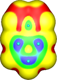
Calculated charge distributions in molecules can easily be visualized by using electrostatic potential maps. The color red is used to indicate electron-rich regions of a molecule while the color blue is used to indicated electron-poor regions. An easier method for visually representing electron displacement in a molecule uses a crossed arrow. By convention the arrow point in the direction of the electron-rich region of a molecule and away from the electron-poor. An example is shown in the molecule fluoromethane. The C-F bond is polarized drawing the bonding electrons toward the more electronegative fluorine giving it a partial negative charge. Consequently, the bonding electrons are drawn away from the less electronegative carbon giving it a partial positive charge. The the electron-rich fluorine is shown as red in the electrostatic potential map and while the electron-poor carbon is shown as blue. The crossed arrow points in the direction of the electron-rich fluorine.
Electrostatic Potential Map and Dipole Moment of Fluoromethane
Chemists often use the term, inductive effect , to describe the shifting of electrons in a sigma by the electronegativity of atoms. Relatively electronegative atoms, such as fluorine, tend to inductively draw electrons towards themselves and away from nearby atoms. The inductive effect will be used to explain chemical reactivity in many situations in organic chemistry. An excellent example of the inductive effect is seen when comparing the O-H bond polarities of water (H 2 O) and hypochlorous acid (ClOH). Replacing the less electronegative hydrogen (EN = 2.1) in water with the more electronegative chlorine (EN = 3.0) in hypochlorous acid creates a greater bond polarity. The chlorine draws electrons away giving the hydrogen a greater partial positive charge. This is shown in the electrostatic potential map as an increase in the blue color around hydrogen.
A "spectrum" of bonds
There is no clear-cut division between covalent and ionic bonds. In a pure non-polar covalent bond, the electrons are held on average exactly half way between the atoms. In a polar bond, the electrons have been dragged slightly towards one end. How far does this dragging have to go before the bond counts as ionic? There is no real answer to that. Sodium chloride is typically considered an ionic solid, but even here the sodium has not completely lost control of its electron. Because of the properties of sodium chloride, however, we tend to count it as if it were purely ionic. Lithium iodide, on the other hand, would be described as being "ionic with some covalent character". In this case, the pair of electrons has not moved entirely over to the iodine end of the bond. Lithium iodide, for example, dissolves in organic solvents like ethanol - not something which ionic substances normally do. Many bonds between metals and non-metal atoms, are considered ionic, however some of these bonds cannot be simply identified as one type of bond. Examples of this are the lithium - carbon bond in methyllithium which is usually considered as polar covalent (somewhat between covalent and ionic) and the potassium - oxygen bond in potassium tert -butoxide which is considered more ionic than covalent.
Covalent bonds form when electrons are shared between atoms and are attracted by the nuclei of both atoms. In pure covalent bonds, the electrons are shared equally. In polar covalent bonds, the electrons are shared unequally, as one atom exerts a stronger force of attraction on the electrons than the other. The ability of an atom to attract a pair of electrons in a chemical bond is called its electronegativity. The difference in electronegativity between two atoms determines how polar a bond will be. In a diatomic molecule with two identical atoms, there is no difference in electronegativity, so the bond is nonpolar or pure covalent. When the electronegativity difference is very large, as is the case between metals and nonmetals, the bonding is characterized as ionic.
- No electronegativity difference between two atoms leads to a non-polar covalent bond.
- A small electronegativity difference leads to a polar covalent bond.
- A large electronegativity difference leads to an ionic bond.

- Which of the following atoms is the more electronegative?
3. Which of the following molecules would you expect to have the more polarized O-H bond?
The molecule on the right would have the more polarized O-H bond. The presence of the highly electronegative fluorines would draw electrons away by the inductive effect
2.1 Polar Covalent Bonds: Electronegativity
2.1 exercises.
Rank the following from least polar to most polar using knowledge of electronegativity
CH 3 CH 2 -Li CH 3 CH 2 -K CH 3 CH 2 -F CH 3 CH 2 -OH
(least polar) OH < F < Li < K (most polar)
- Architecture and Design
- Asian and Pacific Studies
- Business and Economics
- Classical and Ancient Near Eastern Studies
- Computer Sciences
- Cultural Studies
- Engineering
- General Interest
- Geosciences
- Industrial Chemistry
- Islamic and Middle Eastern Studies
- Jewish Studies
- Library and Information Science, Book Studies
- Life Sciences
- Linguistics and Semiotics
- Literary Studies
- Materials Sciences
- Mathematics
- Social Sciences
- Sports and Recreation
- Theology and Religion
- Publish your article
- The role of authors
- Promoting your article
- Abstracting & indexing
- Publishing Ethics
- Why publish with De Gruyter
- How to publish with De Gruyter
- Our book series
- Our subject areas
- Your digital product at De Gruyter
- Contribute to our reference works
- Product information
- Tools & resources
- Product Information
- Promotional Materials
- Orders and Inquiries
- FAQ for Library Suppliers and Book Sellers
- Repository Policy
- Free access policy
- Open Access agreements
- Database portals
- For Authors
- Customer service
- People + Culture
- Journal Management
- How to join us
- Working at De Gruyter
- Mission & Vision
- De Gruyter Foundation
- De Gruyter Ebound
- Our Responsibility
- Partner publishers
Your purchase has been completed. Your documents are now available to view.
Using electrostatic potential maps as visual representations to promote better understanding of chemical bonding
Static visual representations (VRs) of chemical structures are necessary for an understanding of chemical bonding, a topic which continues to lead to learning difficulties and misconceptions for many students. The efficacy and problems associated with the use of VRs of chemical structures and chemical bonding in the form of electrostatic potential maps resulting from accurate quantum mechanical calculations are the subject of this study, which involved a sample of first year, second semester students, studying the elective course “Science Education” ( N = 31). Students distinguished between nonpolar and polar covalent bonding, however, they encountered difficulties with concepts related to ionic bonding. Most students did not employ multistructural thinking (in the sense of the SOLO taxonomy), when providing explanations about the variation of bond polarity. Persistence of a covalent-ionic bond dichotomy was apparent, while for some, ions can be involved in both ionic and covalent bonding. Many students preferred to use their established high school knowledge. On a positive note, many students were clearly affected by the information provided by the colored VRs. Finally, the minimal experience of our students with these VRs leads us to believe that a more systematic and extensive coverage would be likely to produce improved outcomes.
Introduction
The use of models and images (in general, of visual representations ) are vital to our understanding of chemistry, with physical models of molecules providing tools for visualization of the molecular world for both learners and researchers. Such static images have become a sine qua non for chemistry textbooks. Visualization of a range of phenomena is clearly necessary for development of an understanding of chemistry ( Ferk, 2003 ; Gkitzia, Salta, & Tzougraki, 2011 ; Kozma & Russell, 1997 ; Wu, Krajcik, & Soloway, 2001 ) so, in recent years, images, as a rule colored images, have taken up more and more space in textbooks. In addition, the use of technology, especially of personal computers and smart phones, has been increasingly important in enhancing both student interest and learning ( Kelly & Akaygun, 2019 ). For instance, VandenPlas, Herrington, Shrode, and Sweeder (2021) developed and used online materials (simulations and screencasts) to support students’ learning of chemistry outside of a face-to-face classroom, with a focus on student understanding of the concepts of force and energy changes as they pertain to bonding and intermolecular attractions. Also, Isaloka and Dwiningsih (2020) produced 2D interactive multimedia to display special-visual orientations of polar and nonpolar covalent bonds, and evaluated their content validity, construct validity and practicality, while Brown, Whaley, and Hyslop (2020) compared the effectiveness of three methods (virtual reality, computer simulation, and traditional modeling) used in teaching molecular geometry to college chemistry students, and reported that while differences among the three methods were not significant, the results showed that the virtual reality method resulted in more enthusiasm and positive attitudes toward the topic among the students.
However, the mere use of images and technology does not guarantee their effectiveness in promoting learning and it may even contribute to the formation of misconceptions by students. Learning outcomes appear to depend on both the quality and the pedagogic content of the images and also on how the images and the technology are used ( National Research Council, 2012 ). In particular, the speed with which a user can access different representations of molecules in a technology enabled environment can provide important benefits to cognitive development ( Polifka, Baluyut, & Holme, 2021 ). Education research has definitively an important role to play here in assessing the outcomes and the effectiveness of these tools.
One topic where visual representations currently play a crucial role is that of chemical bonding, which is fundamental to the teaching of chemistry ( Atkins, 1999 ; Gillespie, 1997 ; Holme & Murphy, 2012 ; Holme, Luxford, and Murphy, 2015 ; Taber & Coll, 2003 ). Chemical bonding is associated with the understanding of many chemistry concepts, such as chemical reactions and structure–property relationships, but continues to be difficult for teachers to organize and teach and for students to learn and understand. The initial focus here is on the teaching and learning of basic bonding concepts in upper secondary education (grades 10th to 12th). Prevailing approaches to teaching chemical bonding continue to lead to learning difficulties and misunderstandings for many students, with many of these misunderstandings proving resistant to instruction (e.g. Levy Nahum, Mamlok-Naaman, Hofstein, & Krajcik, 2007 ; Nicoll, 2001 ; Özmen, 2004 ; Taber & Coll, 2003 ).
Taber (1998) proposed an ‘alternative conceptual framework’ for chemical bonding, according to which the ‘octet rule’ is used by the students as an explanatory framework for chemical stability and reactivity, and he further identified the four key “pedagogical learning impediments” to the effective teaching and learning of chemical bonding ( Taber, 2001 ): (1) an atomic ontology and the initial atomicity; (2) the over-generalization of the octet rule; (3) the dichotomous classification of bonding; and (4) the use of anthropomorphic language , with student explanations commonly phrased in terms of what an atom might ‘want’ or ‘need’” ( Taber & Adbo, 2013 , p. 348). Taber (1999) considered this framework as a largely coherent theory-like basis for thinking about chemical stability, change and bonding (for a review, see Taber, 2013 ). In addition, Taber (2001) introduced a curricular model of chemical bonding, which starts with metallic structures, then goes on to ionic structures, to giant covalent structures, and finally to simple molecular structures. The model emphasizes molecules and ions (rather than atoms) as the basic unit of matter, so as to avoid the assumption of initial atomicity, while the nature of bonding, structures, and properties of substances are explained in terms of electrostatic forces, but not the octet rule, nor the desires of atoms. Addressing bonding in terms of electrostatics could also serve as a good foundation for subsequently learning about electronegativity, bond polarity, hydrogen bonds, and solvent-solute interactions.
Levy Nahum et al. (2007) (see also Kronik, Levy Nahum, Mamlok-Naaman, & Hofstein, 2008 ; Levy Nahum, Mamlok-Naaman, & Hofstein, 2013 ; Levy Nahum, Mamlok-Naaman, Hofstein, & Taber, 2010 ) also developed “a new teaching approach for the chemical bonding concept aligned with current scientific and pedagogical knowledge”. A qualitative description that is conceptually consistent with quantum mechanics was adopted, providing an answer to the question “what really causes atoms to interact and form a chemical bond?” The authors suggested the ‘ bottom up ’ approach for teaching the bonding concept. The crux of the suggestion is that bonding should be taught based on elementary principles and by using the idea of a continuum of bond strengths, removing the artificial dichotomous division between different types of bonding.
In a preceding publication, we reviewed studies concerning students’ conceptual difficulties with the topic of chemical bonding, tested the knowledge of 10th-grade Greek students on certain key aspects of bonding and presented our findings from the use of an enriched teaching text on this topic ( Tsaparlis, Pappa, & Byers, 2018 ). The enriched text started with covalent bonding between atoms of the same or different chemical elements and the nature of the bonding but postponed the study of bond polarity (polar covalent bonds) until after discussing ionic bonding. It included a careful discussion about the octet rule, paid particular attention to features that characterize both the covalent and the ionic bond, and gave a more detailed coverage of electronegativity, stressing its importance to the understanding of the continuum between ionic and covalent bonding. The intervention introduced with the treatment group demonstrated mixed results, with statistically significant differences being detected for some concepts/knowledge elements, but not for others. Finally, in a follow up study to our previous one ( Tsaparlis, Pappa, & Byers, 2020 ), we reviewed studies on student understanding and on teaching of bonding concepts and presented proposals for the teaching of chemical bonding at secondary level based on the findings of our own study ( Tsaparlis et al., 2018 ). The proposals included a spiral curriculum spanning all three upper-secondary grades, plus a learning progressions approach, employing lower and upper anchors of relevant scientific knowledge and a proposed list of potential core concepts, lever concepts, and stepping-stones.
The net conclusion is that critical details and some sophisticated reasoning are required for an understanding of chemical bonding, for example the many types of bonding (metallic, ionic, covalent, polar and non-polar bonding, intermolecular bonding). It is crucial to have in mind that, because bonding is taught at both the (mainly upper) secondary and the tertiary level, there is an overlap of concepts, instructional tools and approaches between the secondary and the first-year undergraduate level. Although, complexity is present from the early stages, it deepens as we move from secondary to tertiary education.
The ionic bond is referred to as just a transfer of electrons between separate atoms in order to acquire full valence shells and satisfy the octet rule.
Covalent and ionic bonds are often presented in isolation, as bonds that share electrons and bonds that transfer electrons respectively.
Bond polarity is directly linked to the covalent bond. As a consequence, students fail to realize the covalent-ionic bond continuum.
Ions are involved in both ionic and covalent bonding (deriving from the knowledge that a polar covalent bond possesses some ionic character).
In the final part of a previous paper, we considered the pros and cons of teaching a modern qualitative quantum mechanical approach to bonding ( Tsaparlis et al., 2020 ). Despite the fact that the teaching of modern qualitative quantum mechanical descriptions of atomic and molecular structure at secondary level has been criticized by some chemistry educators ( Bouayad, Kaddari, Lachkar, & Elachqar, 2014 ; Tsaparlis, 1997a , 1997b , 2013 ), there is no doubt that quantum mechanics can refine one’s understanding about the submicroscopic world. Atomic orbitals, their physical interpretation, as well as electron configurations of atoms and monoatomic ions are often discussed in upper secondary school. Although molecular orbitals are not generally introduced, Lewis structures, possibly hybrid atomic orbitals, use of the VSEPR model to discuss molecular structure and consideration of electron clouds and their overlap in bonding are all likely to be beneficial to students’ understanding. Pauling’s proposal that beginning courses in chemistry should emphasize the simpler aspects of molecular structure in relation to the properties of substances is clearly of relevance here. According to Pauling (1992) , concepts to be covered should include the electronic structure of the atom, with emphasis on the noble-gas structure, the shared electron-pair bond, the tetrahedral carbon atom, the electronegativity scale, the partial ionic character of bonds, and the idea of resonance as applied to the benzene molecule; but molecular orbitals should not be introduced at this stage.
Some researchers have encouraged early introduction of a quantum mechanical approach. For example, considering upper-secondary and first-year undergraduate students, Dhindsa and Treagust (2014) used the valence-bond model of bonding to explain covalent bonding in terms of the overlap of atomic orbitals on bonded atoms, while Nimmermark, Öhrström, Martensson, and Davidowitz (2016) , based on data concerning Swedish undergraduate students, suggested that it is likely to be beneficial to the understanding of bonding (and especially the covalent bond) if secondary-school students have been introduced to at least a simplified quantum model of the atom. Although the physical interpretation of atomic orbitals and the electron configurations of atoms and monoatomic ions may be useful, molecular orbitals should certainly not be introduced at the secondary level, and only Lewis structures and the VSEPR model should be used to consider molecular structures at this stage. It appears that the teaching of certain aspects of the molecular quantum mechanical model in secondary education, such as electron clouds and their overlap in bonding, can be beneficial to students and should not be ruled out. However, modern quantum-chemical concepts should only be introduced, with great care ( Dunstan, 1968 ; Tsaparlis, 1997a , 1997b ).
The importance of static visual representations of chemical structures resulting from quantum mechanical calculations
It is known that conventional undergraduate courses on quantum chemistry tend to be strongly mathematically oriented and this poses a learning impediment to most students, making it hard for them to gain conceptual understanding of the relevant concepts ( Tsaparlis, 1997a , 2013 ). On the other hand, qualitative approaches, which are based on the visualization of atomic and molecular orbitals and, as a rule, are employed in introductory general and inorganic chemistry courses, may also fail to provide a clear physical picture. For Barradas-Solas and Sánchez Gómez (2014) , the use of graphical representations of orbitals have characteristics that fall into the category of alternative conceptions or misconceptions and this has even led to suggestions that these ‘chemical’ orbitals should be omitted from chemistry education altogether. In any case, to be effective, such approaches require great care ( Tsaparlis & Papaphotis, 2009 ). Dangur, Avargil, Peskin, and Dori (2014) employed a qualitative visual-conceptual approach to teaching quantum chemistry (including bonding concepts, and emphasizing interdisciplinary real-life applications) and investigated the effectiveness of the approach on students’ visual and textual understanding of quantum mechanical concepts. According to their findings, the textual and visual understanding of quantum mechanical concepts and the ability to move across illustrations and explanations were significantly improved for high school honors and undergraduate chemistry students, who were exposed to this approach. Polifka, Baluyut, and Holme (2021) have used a “Variable Representation Assessment” tool, with which questions and responses are delivered via a web browser, and which can provide formative information about how students in a course are utilizing molecular representations to respond to questions about molecular properties that can be inferred from such representations. Using this tool, students in a US general chemistry course navigated among five different representation styles: (1) chemical formulas; (2) Lewis structures; (3) wedge and dash structures; (4) ball and stick structures; and (5) electrostatic potential maps. Results suggested that students needed to utilize a better balance among the various molecular representations. It was concluded that the preponderance of use of Lewis structures in many chemistry lessons might have led students to limit their use of a wider range of representations, while the students’ apparent lack of familiarity with electrostatic potential maps seems likely to have contributed to their relative aversion to using them.
Supplementary Material S1 discusses the concept of electron probability density (or simply electron density ) ( Jensen, 2010 ; Matta & Gillespie, 2001 , 2002 ; Pilar, 1967 ), while Supplementary Material S2 describes the method of construction and interpretation of isodensity surfaces and electrostatic potential maps ( Anslyn & Dougherty, 2006 ; Reed College, 2021 ). Note that this knowledge is supplied here for the benefit of the readers, but it was not part of the teaching and knowledge of the students in our study. Also, although electrostatic potential ranges were not included in the electrostatic potential maps used, it is important and useful to compare structures with the same electrostatic potential ranges (see Supplementary Material S2).
The present study – research questions
How do students interpret colored VRs when presented with them for the first time? Or equivalently:
Are students able to immediately decode and incorporate/synthesize colored VRs into their previous chemistry knowledge?
To what degree did the provided static colored VRs help the students to:
deduce the type of bonding in various molecules?
explain the variation of bond polarity in various molecules?
exploit the difference in size between an atom and its corresponding ion?
comprehend the concept of a continuum of bonding type and overcome the common misconception that bond polarity is only a feature of covalent bonds and not of ionic bonds? In addition:
What types of static VRs for common covalent molecules, such as H 2 and H 2 O, are the students already familiar with?
How does the information that students can obtain from the colored VRs resulting from quantum mechanical calculations compare with the information that they can obtain from the VRs that they are already familiar with?
The students of our study ( Ν = 31) were in their first year, second semester (age 18–19), studying the elective course “Science Education” in the Department of Chemistry at the University of Ioannina, in the spring semester of the academic year 2018–19. The purpose of the course was to function as an introduction to content knowledge and pedagogic content knowledge which is relevant to the profession of a secondary school chemistry teacher. Students take this course because “Chemistry Education” is prescribed by the Greek Ministry of Education and by Greek law as one of the tests to be taken by secondary chemistry teacher candidates.
The lecturer, who was one of the authors of this paper (GP), is a secondary science teacher with a first degree in physics, and a holder of a M.Sc. and a Ph.D. in science education and was hired to teach this course within a project offering university teaching experience to recent Ph.D. graduates. Instruction was carried out in Greek and followed an in-class lecture format, with the instructor adopting an interactive approach, making efforts to engage the students in thinking, questioning and discussion during the lectures. The students (both male and female, with females outnumbering males: 19 vs. 12) were majoring in chemistry and used Greek science education textbooks (in Greek) that were recommended for this course by the instructor.
The study utilized a final written in-class closed-book examination in June 2019. There were four sections in the examination paper, but only section D is relevant to this study and has been reproduced in English in Supplementary Material S3. The duration of the examination was 3 h, but the distribution of time to each section and question was left entirely up to the student.
The instrument
Section D of the examination consisted of four questions. Question D.1 (which addressed research question RQ5 and is also related to RQ6) asked the students to draw as many VRs as they knew about the hydrogen molecule (H 2 ) and the water molecule (H 2 O). Question D.2 involved five parts and related to a set of colored static structures, in the form of electron potential density (EPD) surfaces, which have resulted from proper quantum mechanical calculations of high accuracy ( Jensen, 2010 ). The electrostatic potential map for hydrogen fluoride was not included with the hydrogen halide molecules because its intense polarization, as shown through coloring, makes it very similar to the coloring of LiH, hence there was the fear that HF could be taken by the students as being essentially ionic (see Figure 1 ). Figure 2 shows the electrostatic potential maps used in the study. [1] Note that dipole moments, electronegativity differences and gas phase bond lengths were not supplied for the hydrogen halide molecules. [2]

The electrostatic potential maps for the hydrogen halide molecules HF, HCl, HBr and HI, where the colors show differences in chemical bond polarity. The dipole moments μ (in D) are 1.86 for HF, 1.11 for HCl, 0.788 for HBr, and 0.382 for HI. The corresponding Pauling electronegativity differences are 1.78/0.96/0.76/0.46. Note that the shapes shown do not reproduce the relative actual molecular sizes: the gas phase bond lengths D(H–X) (in pm) are 91.7 for HF, 127.4 for HCl, 141.4 for HBr, and 160.9 for HI.

The electrostatic potential maps used in the main study, including a color code scale for the polarity of electrostatic potential.
For convenience of reference for the reader, the five parts of question D.2 are listed in Table 1 , along with the research questions they were designed to address.
The five parts of question D.2 and the corresponding research questions (see also Figure 2 ).
Question D.3 (which addressed research question RQ2) provided pictures of colored VRs for two organic molecules with similar structures (CH 3 Li and CH 3 Cl) (see Figure 3 and Supplementary Material S3), and asked students to identify and justify which structure corresponded to which molecule. Note that the diagrams used for question D.3 (which were taken from the internet) have certain drawbacks, such as the weakness of the blue and red coloring, as well as the sizes of the shown nuclei of the chlorine and the lithium atoms, which must have caused problems to the students. This was taken into account when marking the students’ answers. Finally question D.4 (which addressed research question RQ6 and is also related to all previous research questions) was of a metacognitive nature and asked students to compare the VRs for the hydrogen molecule and the water molecule that they drew in answering question D.1 with the corresponding colorful quantum mechanical VRs.

Visual representations of chemical structures referring to chloromethane (CH 3 Cl) and methyllithium (CH 3 Li) from question D.3. (Students were asked to identify and justify which one corresponds to CH 3 Cl and which to CH 3 Li and why?).
Ethical considerations
Every effort was made to observe the rules of good ethical conduct for implementing a social research study with university students ( Taber, 2014 ). The students answered the questions as part of their final examination in the science education course, that is, they were not given any choice over taking part. Institutional permission to use formal examination material in the research was not required, but the lecturer had to report on the course and the exam to a departmental professor. In addition, the students were informed that the particular questions would be used as part of an education research study and no objections were received. All students provided written consent to the use for their responses for the stated research part of the test. Although the students were required to provide their names, as the questions were part of the examination, with responses contributing to their course mark, their names were not to be revealed to any third parties.
Method of analysis
A variety of assessment approaches was adopted for marking the scripts. Three of the authors agreed on the assessment approaches to be used. Question D.1 was marked on the basis of a sequence of expected VRs for the H 2 and H 2 O molecules. In the case of H 2 , half of the marks were assigned for the inclusion of the ellipsoid isodensity surface (a ‘flattened sack’) for H 2 [see maps (a) right in Figure 2 , and the top right shape in the answer of student #18 in Figure 4 ]. The marking is evident from the answers provided by the two best students, as shown in Figures 4 and 5 . Question 4 was of a metacognitive character and its marking was based on a list of expected points of view. In the cases of question D.2 (with the exception of part D.2e) and question D.3, the SOLO taxonomy was considered most appropriate. SOLO stands for “ Structure of Observed Learning Outcomes ”, and is suitable for open-ended questions where the complete answer involves many factors; it may, in addition, require relational and abstract thinking. More specifically, it classifies students’ responses into five levels of understanding from the simplest to the most complex: (1) pre-structural, (2) uni-structural, (3) multi-structural, (4) relational, and (5) extended abstract ( Biggs, 1999 ; Biggs & Collins, 1982 ). Extended abstract understanding is essential for complex conceptual situations and for real problem solving. Further information about the SOLO taxonomy and the marking scheme employed can be found in Supplementary Material S4. In our case, we first considered what should be expected as a complete answer for each question, and then judged the SOLO level that was required. Using this approach, we concluded that all questions were relatively straightforward, so extended abstract thinking was not required to answer any of them. Two parts (D.2b and D.2c) required only multi-structural thinking, while a further two parts (D.2a and D.2d) were more complex requiring relational understanding in addition to multi-structural thinking. Part D.2e required students to mention two features that the colored visual representations (VRs) help us to understand, so declarative and partly procedural knowledge were likely to be sufficient here, making the marking of this question relatively straightforward.

Student #18’s drawings in response to question 1. This student was marked 100% for the structures for H 2 and 96% for the structures of H 2 O.

Student #16’s drawings in response to question 1. This student was marked 50% for the structures for H 2 and 93% for the structures of H 2 O.
Reliability of the marking of the scripts was ensured on the one hand by the students’ scripts being subjected to three rounds of marking by one author (GT) according to a pre-determined marking scheme. The correlations between markings were positive and very strong. For example, the Pearson correlation coefficient between the second and the third marking for question D.2a was r = 0.851, while the corresponding Spearman coefficient was ρ = 0.835; also the Pearson correlation coefficient between the second and the third marking for question D.3 was r = 0.936, while the corresponding Spearman coefficient was ρ = 0.878. In addition, ten of the student scripts were marked by another author (EP) according to the set marking scheme. After the dissolution of discrepancies by discussion, the Pearson correlation coefficients between the two markers ranged from 0.831 to 0.980, and the Spearman correlation coefficients (with one exception: 0.583) ranged between 0.766 and 0.969.
In addition to descriptive statistics, quantitative data were subjected to an inductive analysis, employing nonparametric statistics tests, as follows: the Friedman test for comparing multiple measures and the Wilcoxon signed-ranks test (with a Bonferroni correction applied) for carrying out paired comparisons. Nonparametric statistics was adopted because of the limited sample size and the non-conformity of the data to normal distribution in most cases. Statistical analyses were made using the SPSS package. However, the main emphasis of our reported results is on qualitative conclusions based on students’ written justifications of their answers. The examination paper and students’ written responses were in Greek. Accuracy of translation into English was checked by back translation of the English version into Greek by one of the authors (GT). The two Greek versions (original and back-translated) were then compared, some changes to the English version were made and the final text in English was checked by another author (BB) ( Brislin, 1970 , 1986 ).
Results and discussion
Descriptive statistics.
The mean mark obtained by the 31 students on section D was 52.9% (s.d. 16.2%), reflecting a moderate performance. There were seven students (22.6% of all students) who achieved a mark >70% (students # 18, 8, 27,16, 9, 12, and 4, with student #18 achieving the highest mark 77.4%). Table 2 shows descriptive statistical data for each of the four questions and the total mark for section D. We note that the highest mean mark was for question D.2 (57.9%) and the lowest for questions D.1 (37.3%).
Results of descriptive statistics: Percent achievement on the individual questions and overall performance on section D.
Inductive statistical analysis I: comparison of the individual questions D.1, D.2, D.3 and D.4 of section D
The Friedman test statistic is χ 2 (3) = 8.089, which is significant ( p = 0.044). Table 3 shows the statistical comparisons between pairs of questions D.1, D.2, D.3 and D.4, according to the Wilcoxon signed-ranks test. It is seen that question D.1’s differences from questions D.2, D.3, and D.4 are statistically significant (for D.1–D.2, and D.1–D.3, p < 0.01; for D.1–D.4, p < 0.05), while D.2 and D.3, as well as D.2 and D.4 and D.3 and D.4 are not differentiated between themselves. It is concluded that while D.1 proved the most difficult question, the performances on D.2, D.3 and D.4 were all similar.
Paired comparisons of questions D.1, D.2, D.3 and D.4 on the basis of the Wilcoxon signed-ranks test. Values of z statistic, with 2-tailed significance level ( p ) within parenthesis.
a Based on negative ranks. b Based on positive ranks.
Question D.1: visual representations of the hydrogen and water molecules
Question D.1 showed the poorest achievement (37.3%), and this was the case for both its parts (see Table 4 ), dealing with VRs for the hydrogen and the water molecule respectively. The poor results resulted from the fact that many students used only simple structural formulas: H–H and linear and/or bent H–O–H, plus the corresponding Lewis structures. Many also used ball & sticks models. Very few included the value (104.5°) for the angle in H 2 O. Several students used models of atoms in molecules, such as two touching and/or overlapping circles for H 2 . Very few used the ellipsoid isodensity surface for H 2 (see Figure 4 ) or the sp 3 hybrid orbitals model for H 2 O (see Figures 4 and 5 ).
Percent achievement on the parts of question D.1.
Figures 4 and 5 show the best two answers (97 and 80% respectively) to question D.1, which were submitted by students #18 ( Figure 4 ) and #16 ( Figure 5 ). Note that student #18 was ranked first with a mark of 77.4% and student #16 was ranked fourth with a mark of 73.4 overall on section D.
Question D.2: using electrostatic potential maps as visual representations
We will now focus on question D.2 and its five parts (see Table 1 and Figure 2 ), which is particularly relevant to the present study. Table 5 shows the descriptive statistics. Students performed well on parts D.2e and D.2c (82.7 and 73.2% respectively). D.2e asked for two features of the colored VRs that help us to understand chemical bonding and most students provided good answers, while part D.2c asked about polar structures among the colored figures. The remaining three questions showed lower mean performances of around the 50% mark. Part D.2a asked for an explanation of the highly polar bond (approaching ionic) displayed in the compound LiH, Part D.2b concerned the color differences displayed by the hydrogen halides HCl, HBr and HI, while D.2d involved the continuity between ionic and covalent bonding. For a complete explanation, all three of these parts required multi-structural SOLO thinking, that is, employment of more than one feature or property was needed. In addition, parts D.2a and D2.d, where a complete answer requires a relational dimension of the SOLO taxonomy, in addition to the multi-structural elements were considered particularly demanding. For this reason, we chose to assign a higher contribution to these two parts in comparison to the other three parts of question D.2 (see Supplementary Material S3).
Percent achievement in the five parts of question D.2.
Inductive statistical analysis II: statistical comparison of the parts of question D.2
The Friedman test gives the test statistic χ 2 (4) = 42.064, which is significant at p < 0.001. Table 6 has the results of post hoc comparisons with the Wilcoxon signed-ranks test. It is seen that the easiest parts D.2c and D.2e are not differentiated between themselves, and the same is true concerning the by pair comparisons between the hardest parts D.2a, D.2b, and D.2d. On the other hand, the differences between D.2a–D.2c, D.2a–D2e, D.2b–D.2c, D2.b–D.2e, D.2c–D.2d, D.2d–D.2e are statistically significant ( p < 0.01).
Paired comparisons of the five parts of question D.2, on the basis of the Wilcoxon signed ranks test. Values of z statistic, with 2-tailed significance level ( p ) within parenthesis.
a Based on positive ranks. b Based on negative ranks.
Qualitative analysis
Ionicity of the compound lih.
Part D.2a asks for a justification of compound lithium hydride being considered ionic on the basis of the electrostatic potential maps (a) (left), (b) and (e) in Figure 2 . The acceptable answer should include that the marked decrease in size of the Li atom (being similar to the size of the Li + ion shown in map (b) right) and its large positive charge indicate that LiH can be essentially thought of as ionic (Li + H − ). This means that the bonding electron pair is not shared but rather belongs almost entirely to H − . The calculation models an isolated LiH molecule in vacuum.
We know of course that discrete molecules of genuine ionic compounds do not exist, with ions only being found in condensed phases. This is supported by the quantum mechanical optimization of the structure of the system consisting of two lithium and two hydrogen atoms, which favors the formation of a dimer, leading to a lattice structure (a crystal) This should be contrasted with the optimization of the geometry of four hydrogen atoms, which leads to the formation of two distinct covalently bonded H 2 molecules ( Jensen, 2010 , p. 110).
Clearly, part D.2a can be considered particularly demanding, because a complete answer requires consideration of both bond polarity and the sizes of ions, with reference to maps (a), (b) and (e), on the question paper (see Figure 2 ), and this requires both multi-structural and relational dimensions of the SOLO taxonomy.
Students were asked to identify the cation and the anion in the compound lithium hydride. Surprisingly, six students suggested that H + was the cation and Li − the anion, although one of these reverted to H − and Li + , when subsequently providing an explanation. It seems likely that these students were very familiar with the H + ion (which is present in aqueous chemistry) but had not encountered the lithium ion, which (being a metal ion) will clearly be the cation.
Only four students, plus another who came close, were able to provide a satisfactory explanation for the ionicity of lithium hydride, with the aid of the provided colored VRs. Performance was moderate (mean of 47.9%) on this part. Complete or nearly complete explanations were expected to include mention of both the plus and minus polarities and the relative sizes of the two ions (with Li + being much the smaller partner). We provide below an example of a nearly “complete” explanation:
Student #23: “Li lies lower (than H) in the periodic table, so it is less electronegative, therefore Η has a larger tendency to attract electrons. Consequently, H is the anion and Li is the cation. From maps (b) it is seen that the Li cation is smaller since it loses one electron, and its color is blue … and acquires a positive charge. On the other hand, H, which acquires a negative charge, becomes red. Therefore, with the formation of ionic bond between them, the representation in map (e) results” [ Note that this student, and also many others, were exact in their response to the first subquestion and just stated which is the cation and which the anion, without referring to their actual charges (Li + and H − ). Several other students, however, did write the Li + and H − ions ].
It is true that this student’s answer to the first subpart of D.2a was based on noting trends in electronegativity related to placement within the periodic table. This allowed the student to deduce that H would be the anion and Li the cation. This information was then mapped onto the VR to deduce which side is lithium and which side is hydrogen. Although most students utilized the color coding and electronegativity difference and/or the bond polarity, few made reference to the size of the two bonded entities:
Student #3: “Li + , H − . Ionic is the compound in map (e) because, as we see from the colors, the compound contains one blue color (the cation) and one red color (the anion)”.
Student #1: “From the colors [the color scale] for electronegativity, we see blue and red colors in Li–H, which means that there is a large difference in electronegativity, therefore the bond is much polarized, so that the elementary charges become nearly unity and we have an ionic compound (Besides, Li is a metal, so it does not make covalent bonds)” ( Note the more elaborate answer here ).
It is noteworthy that 10 students did not refer to the color coding for bond polarity at all, but instead used various arguments concerning the “mechanism” for ionic bond formation (the “history conjecture”, including anthropomorphic elements) ( Taber, 2013 ):
Student #26: “It is about an ionic compound because as Li has one electron, which is … donated to H, which has already one electron and wants to fill a He noble-gas structure. In map (e) we see that the bond is ionic because of the polarity difference, which is considerable” ( Note, the reference to the large bond polarity seems likely to have been deduced from the color differences observed ).
This argumentation is consistent with the approach taught in the upper secondary education (10th grade) chemistry lessons for these students (see Tsaparlis et al., 2018 ).
The polar character of the bonds in hydrogen halides and its chromatic interpretation
Part D.2b asked students to identify what the color differences of the HCl, HBr and HI hydrogen halides in maps (d) show. A complete answer required reference to both bond polarity and the difference in electronegativity among the three halogen atoms, as well as an explanation for the variety in the coloring. Most students used just one feature, and answers were often very short or vague. This accounted for the poor performance (mean of 50.2%) on this part.
Student #11: “[The color differences] show the difference of electronegativity between HCl, HBr, HI” [Similar: #12].
Student #17: “[It shows] where the charge is displaced”.
Student #10: “The color difference of the HCl molecule shows that from positive becomes negative, for HBr shows that from positive becomes neutral, while HI is a neutral molecule”.
Several students referred to ionic bonds or to ions, especially in the case of HCl:
Student #13: “[The color difference] shows the polarization of the ionic bond”.
Student # 23: “The stronger the ionic bond, the more intense and distinct the colors are in the quantum mechanical structures. Therefore, the color differences show the reduction of the electronegativity from Cl − to I − ".
Student # 6: “They show the larger overlap of the H + atom by the anions, because of their size and their electronegativity. [In terms of size] the case is that I − > Br − > Cl − ”.
Student #4: “The color differences of these molecules show the difference in electron density, and in this way we realize the ionic nature of the molecular bond and that there is a difference in electronegativity. The last molecule, HI, could even have a covalent bond because the electrons are nearly evenly distributed”.
Student #15: “The color differences show the difference in polarization of the atoms that make up each molecule; in short, they show the kind of the bond, which tends to ionic bond and which [tends] to covalent bond. Accordingly, HCl makes an ionic bond, where Cl pulls the common electron pair; HBr, where Br pulls a little the electrons; and HI makes covalent bond and shares the electrons”.
Note the elaborate wording of students #4 and #15, despite their conceptual deficiencies. Others referred to ‘ionicity’, meaning apparently the varying ‘ionic character of the (covalent) bond’:
Student #3: “The color changes show the difference of electronegativity between Cl, Br, I; that is, HCl is more ionic compound, while HBr and HI are not so ionic”.
Finally, we quote the best and three other very good answers to part D.2b (according to our marking):
Student #8: “The color difference show the change in bond polarity (HCl > HBr > HI). The larger the electronegativity difference, the more polarized the bond is: HCl, large difference, → much polarized; HBr, moderate difference, → little polarized; HI,small difference, → the least polarized [Similar: #9 and #26].
Student #22: “[They show] that because, in terms of the electronegativity, Cl > Br > I, … the particular coloring happens, because Cl causes a larger polarity than Br, and Br than I” [Similar: #26].
Student #18: “They show how much polarized each bond is, because of the electronegativity difference”.
Student #14: “The color difference shows bond polarity, that is, [an] electronegativity difference between the two atoms of the molecule. The more electronegative the atom is (Cl > Br > I), the more red is the color of the atom that is joined to H”.
Structures with a chemical bond polarity
Part D.2c asked which of the structures given in maps (c), (d) and (e) show polarity in a chemical bond. Nine students achieved a 100% and 2/3 of the students included in their answer an essentially ionic structure for LiH, which is encouraging, leading to a satisfactory performance (mean mark = 73.2%):
Student #12: “In maps (c), the water molecule is a polar chemical bond because oxygen attracts electrons toward it. In maps (d), HCl shows the largest polarity, and then follow HBr and HI, with much smaller (nearly zero) polarity. In map (e), LiH is a polar chemical bond”.
Student #8: “maps (c): H 2 O; maps (d): HCl, HBr (slightly), HI (almost not); map (e): LiH”.
On the other hand, apparently or implicitly, some students assumed that the LiH bond was nonpolar (Students #3, 25, 28 and 30). “In LiH we cannot talk about (bond) polarity” (Students #28 and 30). This is a known misconception: “Polarity occurs only in covalent bonds but not in ionic bonds” ( Tsaparlis et al., 2018 ). One student (#3) did not include HCl among the polar bonds because (s)he assumed that it was ionic. Actually, several students assumed HCl to be ionic as was found from their responses to part D.2d: # 3, 4, 12, and 16 (for #3 and #4, “it is clearly ionic”). Hydrogen chloride is of course encountered by students as a strong acid, in its ionized form as an aqueous solution, and this seems likely to contribute to the above misconception. However, we have also observed an unfortunate side-effect of the colored representations that appeared to confuse several students: the intense/“thick” blue and red colors were taken as an indication of ionic bonding. This was the case more often with HCl (as compared to HBr and HI) but was also found with H 2 O in some cases. The responses of students #23 and #25 were particularly notable:
“In maps (c), the continuity among bonds is apparent, because the form on the left (H 2 ) shows the covalent bond, while the form on the right (H 2 O) (shows) two ionic bonds” (#23).
“Maps (c) show continuity between covalent and ionic bond because on the basis of the [shown] polarity scale it passes through both stages in the formation of H 2 O” (#25).
What appears to have happened in these cases is that students have naively adopted the ionic-covalent bond dichotomy and failed to appreciate the difference between highly polar covalent and ionic bonding.
The covalent-ionic bond continuity
As we reported earlier, part D.2d which dealt with the continuity between covalent and ionic bonds, had the lowest mean mark (46.3%) among all five parts of question D.2. A complete answer involves both the third (multi-structural) and fourth (relational) dimensions of the SOLO taxonomy. It is noticeable that performance in this question was similar to that for D.2a (47.9%), the only other question requiring the relational level. Four students did not answer the question at all, one merely referred to “map (e)”, while a number of others provided only irrelevant explanations at the pre-structural SOLO level:
Student #6: “Map (e), because none atom dominates, but the charges are different”.
Student #14: “In maps (c), the structures show the difference between ionic and covalent bond, because H 2 does not show polarity (same color everywhere), while in H 2 O a difference in color appears, therefore it is a polarized molecule, that is, it forms a covalent bond”.
A serious problem reflected in several students’ responses to this question (which we referred to earlier) was that of misinterpreting the characteristic contrast between the blue and red colors as an indication of ionic bonding. This could also be a consequence of the fact that most students did not appear to pay attention to the change in size upon formation of ions and use this as a feature of ionic bonding. It is true that maps (d) alone do demonstrate the change of bond polarity on moving from HCl to HI, and these maps were used by most of the students, but map (e) (with the more polar LiH) and maps (c) (with H 2 and H 2 O) provide further support, so a complete answer should employ all maps (c), (d) and (e). We quote below two good answers employing only maps (d):
Student #24: “It [the continuity of bond type] is demonstrated in maps (d) because from the left to the right the difference in electronegativity appears to lessen, and eventually it appears that the electrons appear to be shared equally”.
Student #30: “Maps (d) shows the continuity between ionic and covalent bond because it is evident that the difference in electrochemical potential decides the bond”.
Some students did employ all three sets of maps (four students) or two of these sets (c) and (d) or (d) and (e) (another three students). The best response and another interesting one are reproduced below:
Student #27: “The structures that demonstrate the continuity between ionic and covalent bond are those of LiH, HCl, HBr, HI, H 2 O, because [starting] from LiH where we have very strong charges (the red and blue colors dominate), we move to H 2 O where it [the blue vs . the red coloring] starts diminishing and we arrive at HI, where we have mainly green color in the ends and in the middle. Therefore we do not have polarity as large as in the previous [cases]”.
Student #11: “The continuity between ionic and covalent bond is evident in maps (c), (d) and (e) because of the alternation of colors – appearance of blue-green-red – and as shown in the (color) scale, this change of color explains the above [observations].
Contribution of the colored visual representations to understanding
Part D.2e asked students to refer to two features of the colored VRs that helped them to understand chemical bonding and a mean mark of 82.7% was obtained on this part. Sixteen students’ responses were awarded 100%, and satisfactory answers were submitted by many other students. The few poor answers made reference to only one feature. On the other hand, placing a limit of two features probably restricted the students from referring to the many issues associated with these VRs. Features reported included the extent of polarization of the bonds, the evidence for electronegativity differences, the type of bond formed, the size of atoms/ions and/or the size and form of molecules. There were both short and lengthier good responses:
Student #25: “It helps us deduce the type of bonding, as well as how polarity changes within the molecule”.
Student #8: “(1) The electronegativity of each element (and) consequently the polarity of its bonds. (2) The shape of the electron density in a compound”.
Student #27: “One feature is the existence of ionic, polar covalent and nonpolar covalent bond, [as deduced] from the color scale which shows … the polarity of the bond. Also we realize which atom has the negative and which has the positive charge in the compound”.
Question D.3: an application – visual representations of organic molecules
Question D.3 presented students with colored VRs for two organic molecules which have similar structures, CH 3 Cl and CH 3 Li, [3] (see Figure 3 ) and asked for the identification with justification of the two VRs (which belongs to which molecule). The mean mark was 55.0%. A complete answer should involve not only bond polarities (on the basis of the colorings) but also a comparison between the larger electron cloud of Cl [in structure (a)] as compared to that of Li [in structure (b)]. The following is a good attempt to use both bond polarities and atomic sizes, however, it also refers to Li + and to an ionic bond in CH 3 Li: [4]
Student #9: “Cl has larger size than Li, and this follows from how the charge is distributed around the molecule. Also the bond [in CH 3 Cl] will be covalent, and therefore it will have a smaller polarity. In [the case of] CH 3 Li the bond will be ionic and this follows from the polarity of bond, but also by the fact that Li + , which has a smaller size in comparison to C or to Cl because it has lost one electron”.
Bond polarities in the C–Cl and C–Li bonds respectively, with Cl being electronegative and Li electropositive, as judged from the coloring, were used as a criterion for the explanation, for 17 out of the 31 students. An example:
Student #2: “Structure (a) corresponds to compound CH 3 Cl. Cl is more electronegative than C, so when they are bonded between themselves, the fraction of negative charge shifts toward Cl, so it acquires a red color in the above representation” [And similarly for structure (b)].
Question D.4: features and comparisons of various visual representations
Question D.4 asked for a comparison between the VRs for the hydrogen molecule and the water molecule that students had drawn when answering question (1) and the corresponding colored quantum mechanical VRs. In particular, the features and the advantages of the two visual representations were required. Although six students did not answer this question at all, many students provided more or less extensive answers, covering various aspects and views. Many students were supportive of the quantum mechanical colored VRs, although several realized that they have limitations and are just complementary to the traditional VRs. Some students suggested that they are likely to be more suitable for older students and one student even suggested that they were inferior to the traditional ones:
Student #27: “In VRs [of question 1] we have the elements represented with symbols, and these are more understandable, and also they show better the elements that combine. Also, in these VRs, there is the possibility to represent electrons symbolically around the atoms, and this makes the concept of bond and electron sharing more understandable. Finally, from these VRs we obtain information about the orbitals and the geometry of the molecules (e.g. the angles). On the contrary, in the case of the maps of Figure 2 , we have the electron density and [bond] polarity by means of a color scale. This facilitates understanding about which bond is polar or not, which atom has positive or negative charge in the bond, as well as how this charge is distributed along the bond”.
Student #9: “The simple VRs [of question 1] help simply in understanding of the bond in the molecule, [but] they don’t show clearly the nature of the bond, its type or its polarity. … [On the other hand], the quantum mechanical, color representations offer more information about the bond that is formed, the size of the participating atoms, as well as how polar in this bond”.
Student #28: “In maps (c), the VRs are better because they include color, the H 2 molecule appears in color in the form of a flattened sack. In [the case of] H 2 O, we have color that shows that it has a dipole moment, since the red [color] is on the side of oxygen and the blue on the side of hydrogen …”
Student #8. “It is better to use the color structures when teaching elder students, who have already understood concepts such as chemical bonds, charge, electronegativity of the elements, because while [these] demonstrate very well polarity, bond strength, [and] electron cloud, they do not show clearly the existence of electrons, the existence of bonds, and the presence of individual elements. On the contrary, the structures of question 1 make very distinctively apparent the existence of bonds and of elements [ (s)he means atoms ], the electrons of each element, and the electrons that participate in each bond. However, they do not show the difference in electronegativity, bond polarity, [or] the electron cloud. In conclusion, there is not a single representation which is better than another – we just consider which one is suitable for its purpose.
Student #31: “The [various] VRs present [various] advantages. Concerning the representations of question 1, they show the elements which form the compound, the bonds that connect them, the ‘free’ [non-bonded] electrons, their geometry in space. On the other hand, the color representations show the type of bond, [bond] polarity, the difference in electronegativity … In my opinion, the representations of question 1 show more information about a chemical compound and many details …”
Conclusions and implications
At the outset, we should point out that chemistry teaching in Greek secondary schools has traditionally been carried out with the aid of the chalkboard and textbooks, with particular attention being paid to the symbolic level of chemistry (writing molecular and structural formulas and chemical equations) and to solving computational exercises. Greek students’ experience of physical models of atoms and molecules tends to be limited to the pictures in their secondary-school textbooks, as no attention tends to be paid to them during the teaching. Note also that the chemical knowledge of these students was still immature, as they were just freshman students (at the end of their first year at university), so their responses should be judged taking this limitation into account. Let us first consider the answers to the individual subsidiary research questions posed in this study:
To what degree did the provided VRs help the students to deduce the type of bonding in various molecules?
The situation regarding nonpolar and polar covalent bonding appears encouraging. Part D.2c, which asked which of the structures of maps (c), (d) and (e) in Figure 2 show a chemical bond polarity, got a relatively high mean mark (73.2%). Consideration of LiH (part D.2a), however, where bonding starts to approach ionic caused difficulties (mean mark: 47.9%): only four students, plus another who was very close, provided complete or nearly complete multi-structural and relational explanations, which included mention of both the plus and minus polarities and the relative sizes of the two ions.
To what degree did the provided VRs help the students to explain the variation of bond polarity in various molecules?
When it came to providing explanations (part D2.b), the mean mark dropped from 73.2% (see above) to 50.2%, suggesting that students found difficulty in employing multi-structural thinking, often instead restricting themselves to considering only a single factor, aspect or feature.
To what degree did the provided VRs help the students exploit the difference in size between an atom and its corresponding ion?
The answer here is that only a minority of students appeared to understand the significance of size. It appears that the color scale marking different bond polarities as well as electronegativity differences played a dominant role in students’ impressions about the VRs provided, with size of atoms and ions attracting only limited attention.
To what degree did the provided VRs help the students to comprehend the concept of the continuum of bonding type and overcome the common misconception that bond polarity is a feature of covalent bonds only and not of ionic bonds?
The relevant part (D.2d) got the lowest mean mark (46.3%) among all parts of question D.2, showing persistence in the covalent-ionic bond dichotomy in the thinking of many students. It appears that students readily relapse into a dualistic position when considering highly polar bonds, which is again consistent with the approach taken in the upper secondary education (10th grade) chemistry lessons for these students (see Tsaparlis et al., 2018 ). It is therefore likely to be important to continue to stress the continuum between a non-polar covalent bond and an ionic bond with the latter extreme never being achieved in practice.
Regarding the common misconception that bond polarity is only a feature of covalent bonds and not of ionic bonds, it is difficult to provide a definitive answer because there were cases where students did appear to hold this misconception. In addition, some students appeared to believe that ions can be involved in both ionic and covalent bonding (deriving from the use of blue and red colors to mark bond polarity in both covalent and ionic structures).
What types of static VR for common covalent molecules, such as H 2 and H 2 O, are the students already familiar with?
The findings from question D.1, which had the lowest mean mark (37.3%) among all questions, suggest that few students had available and were familiar with a satisfactory collection of VRs for these common molecules. Here many students drew only the H–H and linear and/or bent H–O–H, plus the corresponding Lewis structures, and/or ball & sticks models. Very few included the H 2 O angle. Although, several students used models of atoms in molecules, such as two touching and/or overlapping circles for H 2 , very few used the ellipsoid isodensity for H 2 or the sp 3 hybrid orbitals model for H 2 O (see Figure 4 ).
On an optimistic note, the students worked with the colored quantum mechanical VRs and many of them expressed positive views about their features, as shown by the range of answers to question D.4 and the high mean mark (82.7%) obtained for part D2.e. Students referred to features such as the extent of polarization of the bonds, the evidence for electronegativity differences, the type of bond formed, and to a lesser extent the size of atoms/ions, thus suggesting that the students were able to appreciate that these colored VRs were able to provide information not available from the VRs that they were already familiar with. On the other hand, several students pointed out limitations of the colored VRs, considering them as merely complementary to the traditional VRs, and considered them as likely to be more suitable for older/more experienced students. The mean performance over the whole of section D, which was only moderate (52.9%, s.d. 16.5%) can be justified by the fact that many students preferred to use their established knowledge, such as the process for ionic bond formation or simple rules such as a bond between a metal and a non-metal is ionic, while a bond between non-metals is covalent, rather than to employ new knowledge involving the colored VRs.
Finally, the fact that the representations used result from quantum mechanical calculations of high accuracy is clearly an asset, which adds to their importance and usefulness. However, it was noteworthy that almost none of the students mentioned this characteristic, probably because the students were not yet familiar with quantum mechanical calculations. In general, students were somewhat uncomfortable with these VRs due to their lack of previous exposure to them. A more systematic and extensive coverage would be expected to lead to better outcomes. Emphasis should clearly be paid not only to color scaling (as this is related to bond polarity), but also to the size and forms of atoms, ions, and molecules. The inclusion of the bond-and-stick model or the tube model inside these electrostatic potential maps could be very helpful in providing a helpful bonding picture within the potential map, thus connecting the classical with the modern picture of bonding.
In conclusion and importantly, the main research question for the present study was: How do students interpret colored VRs when presented with them for the first time? Or equivalently: Are students able to immediately decode and incorporate/synthesize colored VRs into their previous chemistry knowledge? As stated, a substantial limitation of this study was that the students had not encountered the quantum-mechanical colored VRs prior to the examination. Although the students were certainly able to work with the VR maps, it was not clear whether they were actually using the colored VRs to inform their understanding, or, whether they were instead resorting to previous knowledge and other heuristics to map onto the VRs. Further, students found difficulty in employing multi-structural thinking or simply did not feel a need to do so, and restricted themselves instead to considering only a single factor, aspect or feature. So it is not really clear to what extent the VRs helped these students to make the required deductions. It is expected that with exposure to these VRs and the method of constructing them, that students will become familiar and comfortable with their various features and uses.
It is hoped that the findings of the present study will be of interest to teachers looking to improve the teaching and learning of chemical bonding. We believe that these VRs can help in deepening students’ conceptual knowledge of relevant structural matters, and in avoiding the formation of misconceptions derived from deficient knowledge and careless use. It is important that teachers stress the advantages of the colored VRs and provide advice to students on how best to use them. These VRs are not intended to replace other more common VRs but rather to synergistically supplement them by providing a simple new and different picture of the polarization in chemical bonds. Students will of course need practice to learn how best to use these VRs alongside other representations that they are already familiar with. These VRs provide information not only by using color but also through their representation of the size of the atomic cores. While the students in this study, by and large, tended to ignore or pay little attention to the latter factor, it seems reasonable to expect that with practice this should improve.
Acknowledgments
We thank all the students for their contribution in carrying out this study. Georgios Tsaparlis also thanks Professor Jan Jensen for personal communications about the quantum mechanical calculation of a LiH molecule in vacuum.
Author contributions: All the authors have accepted responsibility for the entire content of this submitted manuscript and approved submission.
Research funding: None declared.
Conflict of interest statement: The authors declare no competing financial interest.
Anslyn, E. V., & Dougherty, D. A. (2006). Modern physical organic chemistry . Sausalito, California: University Science Books. Search in Google Scholar
Atkins, P. (1999). Chemistry: The great ideas. Pure and Applied Chemistry , 71 (6), 927–929. https://doi.org/10.1351/pac199971060927 . Search in Google Scholar
Barradas-Solas, F., & Sánchez Gómez, P. J. (2014). Orbitals in chemical education. An analysis through their graphical representations. Chemistry Education Research and Practice , 15 (3), 311–319. https://doi.org/10.1039/c4rp00023d . Search in Google Scholar
Biggs, J. B. (1999). Teaching for quality learning at university . New York, N.Y.: McGraw-Hill/Society for Research into Higher Education/Open University Press. Search in Google Scholar
Biggs, J. B., & Collins, K. F. (1982). Evaluating the quality of learning. The SOLO taxonomy . New York: Academic Press. Search in Google Scholar
Bouayad, A., Kaddari, F., Lachkar, F. M., & Elachqar, A. (2014). Quantum model of chemical bonding: Barriers and learning difficulties. Procedia – Social and Behavioral Sciences , 116 , 4612–4616. https://doi.org/10.1016/j.sbspro.2014.01.994 . Search in Google Scholar
Brislin, R. W. (1970). Back-translation for cross-cultural research. Journal of Cross-Cultural Psychology , 1 (3), 185–216. https://doi.org/10.1177/135910457000100301 . Search in Google Scholar
Brislin, R. W. (1986). The wording and translation of research instruments. In W. J. Lonner & J. W. Berry (Eds.), Field methods in a cross-cultural psychology (pp. 137–164). Newbury Park, CA: Sage Publications. Search in Google Scholar
Brown, C. E., Whaley, B., & Hyslop, R. M. (2020). Visualizing molecular structures and shapes: A comparison of virtual reality, computer simulation, and traditional modeling. Chemistry Teacher International , 3 (1), 69–80. https://doi.org/10.1515/cti-2019-0009 . Search in Google Scholar
Burrows, N. L., & Reid Mooring, S. (2015). Using concept mapping to uncover students’ knowledge structures of chemical bonding concepts. Chemistry Education Research and Practice , 6 (1), 53–66. https://doi.org/10.1039/c4rp00180j . Search in Google Scholar
Dangur, V., Avargil, S., Peskin, U., & Dori, Y. J. (2014). Learning quantum chemistry via a visual-conceptual approach: Students’ bidirectional textual and visual understanding. Chemistry Education Research and Practice , 15 (3) 297–310. https://doi.org/10.1039/c4rp00025k . Search in Google Scholar
Dhindsa, H. S., & Treagust, D. F. (2014). Prospective pedagogy for teaching chemical bonding for smart and sustainable learning. Chemistry Education Research and Practice , 15 (4), 435–446. https://doi.org/10.1039/c4rp00059e . Search in Google Scholar
Dunstan, S. (1968). Principles of chemistry . London: Van Nostrand Reinhold. Search in Google Scholar
Ferk, V. (2003). Students’ understanding of molecular structure representations. International Journal of Science Education , 25 (10), 1227–1245. https://doi.org/10.1080/0950069022000038231 . Search in Google Scholar
Gillespie, R. J. (1997). The great ideas of chemistry. Journal of Chemical Education , 74 (7), 862–864. https://doi.org/10.1021/ed074p862 . Search in Google Scholar
Gkitzia, V., Salta, K., & Tzougraki, C. (2011). Development and application of suitable criteria for the evaluation of chemical representations in school textbooks. Chemistry Education Research and Practice , 12 (1), 5–14. https://doi.org/10.1039/c1rp90003j . Search in Google Scholar
Holme, T., Luxford, C., & Murphy, K. (2015). Updating the general chemistry anchoring concepts map. Journal of Chemical Education , 92 (6), 1115–1116. https://doi.org/10.1021/ed500712k . Search in Google Scholar
Holme, T., & Murphy, K. (2012). The ACS Exams Institute undergraduate chemistry anchoring concepts map I: General chemistry. Journal of Chemical Education , 89 (6), 721–723. https://doi.org/10.1021/ed300050q . Search in Google Scholar
Isaloka, I., & Dwiningsih, K. (2020). The development of 3D interactive multimedia oriented spatial visually on polar and nonpolar covalent bonding materials. JTK: Jurnal Tadris Kimiya , 5 (2), 153–165. https://doi.org/10.15575/jtk.v5i2.8688 . Search in Google Scholar
Jensen, J. H. (2010). Molecular modeling basics . Boca Raton, FL: CRC Press/Taylor & Francis. 10.1201/9781420075274 Search in Google Scholar
Kelly, R., & Akaygun, S. (2019). Visualizations and representations in chemistry education. Chemistry Eduation Research and Practice , 20 (4), 657–658. https://doi.org/10.1039/c9rp90009h . Search in Google Scholar
Kozma, R., & Russell, J. (1997). Multimedia and understanding: Expert and novice responses to different representations of chemical phenomena. Journal of Research in Science Teaching , 34 (9), 949–968. https://doi.org/10.1002/(sici)1098-2736(199711)34:9<949::aid-tea7>3.0.co;2-u . 10.1002/(SICI)1098-2736(199711)34:9<949::AID-TEA7>3.0.CO;2-U Search in Google Scholar
Kronik, L., Levy Nahum, T., Mamlok-Naaman, R., & Hofstein, A. (2008). A new “bottom-up” framework for teaching chemical bonding. Journal of Chemical Education , 85 (12), 1680–1685. https://doi.org/10.1021/ed085p1680 . Search in Google Scholar
Levy Nahum, T., Mamlok-Naaman, R., & Hofstein, A. (2013). Teaching and learning of the chemical bonding concept: Problems and some pedagogical issues and recommendations. In G. Tsaparlis & H. Sevian (Eds.), Concepts of matter in science education (pp. 373–390). Dordrecht: Springer. 10.1007/978-94-007-5914-5_18 Search in Google Scholar
Levy Nahum, T., Mamlok-Naaman, R., Hofstein, A., & Krajcik, J. (2007). Developing a new teaching approach for the chemical bonding concept aligned with current scientific and pedagogical knowledge. Science Education , 91 (4), 579–603. https://doi.org/10.1002/sce.20201 . Search in Google Scholar
Levy Nahum, T., Mamlok-Naaman, R., Hofstein, A., & Taber, K. (2010). Teaching and learning the concept of chemical bonding. Studies in Science Education , 46 (2), 179–207. https://doi.org/10.1080/03057267.2010.504548 . Search in Google Scholar
Matta, C. F., & Gillespie, R. J. (2001). Teaching the VSEPR model and electron densities. Chemistry Eduation Research and Practice , 2 (2), 73–90. 10.1039/B1RP90010B Search in Google Scholar
Matta, C. F., & Gillespie, R. J. (2002). Understanding and interpreting molecular electron density distributions. Journal of Chemical Education , 79 (9), 1141–1152. https://doi.org/10.1021/ed079p1141 . Search in Google Scholar
National Research Council . (2012). Instructional strategies. In S. R. Singer & N. R. Nielsen (Eds.), Discipline-based education research (pp. 119–139). Washington, DC: The National Academies Press. Search in Google Scholar
Nicoll, G. (2001). A report of undergraduates’ bonding misconceptions. International Journal of Science Education , 23 (7), 707–730. https://doi.org/10.1080/09500690010025012 . Search in Google Scholar
Nimmermark, A., Öhrström, L., Martensson, J., & Davidowitz, B. (2016). Teaching of chemical bonding: A study of Swedish and South African students’ conceptions of bonding. Chemistry Eduation Research and Practice , 17 (4), 985–1005. https://doi.org/10.1039/c6rp00106h . Search in Google Scholar
Özmen, H. (2004). Some student misconceptions in chemistry: A literature review of chemical bonding. Journal of Science Education and Technology , 13 (2), 147–159. https://doi.org/10.1023/b:jost.0000031255.92943.6d . 10.1023/B:JOST.0000031255.92943.6d Search in Google Scholar
Pauling, L. (1992). The nature of chemical bond – 1992. Journal of Chemical Education , 69 (7), 519–521. https://doi.org/10.1021/ed069p519 . Search in Google Scholar
Pilar, F. L. (1967). Elementary quantum chemistry . New York: McGraw-Hill. Search in Google Scholar
Polifka, J., Baluyut, J., & Holme, T. (2021). Technology, molecular representations, and student understanding in chemistry. In G. Tsaparlis (Ed.), Problems and problem solving in chemistry education (pp. 323–339). London, UK: Royal Society of Chemistry. 10.1039/9781839163586-00321 Search in Google Scholar
Reed College: Organic Chemistry (ROCO) . (2021). Online, Chapter 4 – Electrostatic potentials . Portland, Oregon: Reed College. https://www.reed.edu/chemistry/ROCO/Potential/electrostatic_maps.html [Accessed 17 May 2021]. Search in Google Scholar
Taber, K. S. (1998). An alternative conceptual framework from chemistry education. International Journal of Science Education , 20 (5), 597–608. https://doi.org/10.1080/0950069980200507 . Search in Google Scholar
Taber, K. S. (1999). Alternative conceptual frameworks in chemistry. Education in Chemistry , 36 (5), 135–137. Search in Google Scholar
Taber, K. S. (2001). Building the structural concepts of chemistry: Some considerations from educational research. Chemistry Education Research and Practice , 2 (2), 123–158. https://doi.org/10.1039/b1rp90014e . Search in Google Scholar
Taber, K. S. (2013). A common core to chemical conceptions: Learners’ conceptions of chemical stability, change and bonding. In G. Tsaparlis & H. Sevian (Eds.), Concepts of matter in science education (pp. 391–418). Dordrecht: Springer. 10.1007/978-94-007-5914-5_19 Search in Google Scholar
Taber, K. S. (2014). Ethical considerations of chemistry education research involving ‘human subjects’. Chemistry Education Research and Practice , 15 (2), 109–113. https://doi.org/10.1039/c4rp90003k . Search in Google Scholar
Taber, K. S., & Adbo, K. (2013). Developing chemical understanding in the explanatory vacuum: Swedish highschool students’ use of an anthropomorphic conceptual framework to make sense of chemical phenomena. In G. Tsaparlis & H. Sevian (Eds.), Concepts of matter in science education (pp. 347–370). Dordrecht: Springer. 10.1007/978-94-007-5914-5_17 Search in Google Scholar
Taber, K. S., & Coll, R. (2003). Bonding. In J. K. Gilbert, O. De Jong, R. Justy, D. F. Treagust, & J. H. Van Driel (Eds.), Chemical education: Towards research-based practice (pp. 213–234). Dordrecht: Kluwer. 10.1007/0-306-47977-X_10 Search in Google Scholar
Tsaparlis, G. (1997a). Atomic and molecular structure in chemical education – A critical analysis from various perspectives of science education. Journal of Chemical Education , 77 (8), 922–925. https://doi.org/10.1021/ed074p922 . Search in Google Scholar
Tsaparlis, G. (1997b). Atomic orbitals, molecular orbitals and related concepts: Conceptual difficulties among chemistry students. Research in Science Education , 27 (2), 271–287. https://doi.org/10.1007/bf02461321 . Search in Google Scholar
Tsaparlis, G. (2013). Learning and teaching the basic quantum chemical concepts. In G. Tsaparlis & H. Sevian (Eds.), Concepts of matter in science education (pp. 437–460). Dordrecht: Springer. 10.1007/978-94-007-5914-5_21 Search in Google Scholar
Tsaparlis, G., & Papaphotis, G. (2009). High-school students’ conceptual difficulties and attempts at conceptual change: The case of basic quantum chemical concepts. International Journal of Science Education , 31 (7), 895–930. https://doi.org/10.1080/09500690801891908 . Search in Google Scholar
Tsaparlis, G., Pappa, E. T., & Byers, B. (2018). Teaching and learning chemical bonding: Research-based evidence for misconceptions and conceptual difficulties experienced by students in upper secondary schools and the effect of an enriched text. Chemistry Education Research and Practice , 19 (4), 1253–1269. (Plus Supplementary files). https://doi.org/10.1039/c8rp00035b . Search in Google Scholar
Tsaparlis, G., Pappa, E. T., & Byers, B. (2020). Proposed pedagogies for teaching and learning chemical bonding in secondary education. Chemistry Teacher International , 2 (1), 20190002. https://doi.org/10.1515/cti-2019-0002 . Search in Google Scholar
VandenPlas, J. R., Herrington, D. G., Shrode, A. D., & Sweeder, R. D. (2021). Use of simulations and screencasts to increase student understanding of energy concepts in bonding. Journal of Chemical Education , 98 (3), 730–744. https://doi.org/10.1021/acs.jchemed.0c00470 . Search in Google Scholar
Wu, H. K., Krajcik, J. S., & Soloway, E. (2001). Promoting conceptual understanding of chemical representations: Students’ use of a visualization tool in the classroom. Journal of Research in Science Teaching , 38 (7), 821–842. https://doi.org/10.1002/tea.1033 . Search in Google Scholar
Supplementary Material
The online version of this article offers supplementary material ( https://doi.org/10.1515/cti-2021-0012 ).
© 2021 Georgios Tsaparlis et al., published by De Gruyter, Berlin/Boston
This work is licensed under the Creative Commons Attribution-NonCommercial-NoDerivatives 4.0 International License.
- X / Twitter
Supplementary Materials
- Supplementary Material Details
Please login or register with De Gruyter to order this product.
Journal and Issue
Articles in the same issue.
- Full property list
- Atomic numbers
- Atomic radii
- Atomic spectra
- Atomic weights
- Block in periodic table
- Boiling point
- Bond enthalpies
- Bond length in element
- Bulk modulus
- CAS Registry ID
- Classification
- Covalent radii
- Critical temperature
- Crystal structure
- Density of solid
- Description
- Effective nucl. charges
- Electron bind. energies
- Electrical resistivity
- Electron affinity
- Electron shell structure
- Electronegativity
- Electronic configuration
- Enthalpy: atomization
- Enthalpy of fusion
- Expansion coefficient
- Enthalpy: vaporization
- Group numbers
- Health hazards
- History of the element
- Hydration enthalpies
- Hydrolysis constants
- Ionization energies
- Lattice energies
- Liquid Range
- Mass in human
- Meaning of name
- Melting points
- Molar volume
- Names and symbols
- Orbital_properties
- Oxidation numbers
- Period numbers
- Poisson's ratio
- Ionic radii
- Radii - ionic, Pauling
- Radii - metallic (12)
- Radii - valence orbital
- Radii - Van der Waals
- Reactions of elements
- Reduction potentials
- Reflectivity
- Refractive index
- Rigidity modulus
- Standard state
- Superconductivity
- Term symbol
- Thermal conductivity
- Thermodynamics
- Velocity of sound
- X-ray mass abs. coeff.
- Young's modulus
- Electronegativity (Sanderson)
- Periodic table gallery
- Period 5spd
- Period 6spd
- s- and p-Block
A definition will appear here.
Pauling scale
- Electronegativity (Allen)
- Electronegativity (Allred-Rochow)
- Electronegativity (Pauling)
- Electronegativity (Mulliken-Jaffe)
- Electronegativity (Mulliken-Jaffe) p-orbital
- Electronegativity (Mulliken-Jaffe - s)
- Electronegativity (Mulliken-Jaffe - sp)
- Electronegativity (Mulliken-Jaffe -sp 2 )
- Electronegativity (Mulliken-Jaffe -sp 3 )
Literature sources
- R.T. Sanderson, J. Chem. Ed. , 1988, 65 , 112.
- J.E. Huheey, E.A. Keiter, and R.L. Keiter in Inorganic Chemistry : Principles of Structure and Reactivity , 4th edition, HarperCollins, New York, USA, 1993.
Thank you for visiting nature.com. You are using a browser version with limited support for CSS. To obtain the best experience, we recommend you use a more up to date browser (or turn off compatibility mode in Internet Explorer). In the meantime, to ensure continued support, we are displaying the site without styles and JavaScript.
- View all journals
- My Account Login
- Explore content
- About the journal
- Publish with us
- Sign up for alerts
- Open access
- Published: 10 May 2024
VOLTA: an enVironment-aware cOntrastive ceLl represenTation leArning for histopathology
- Ramin Nakhli ORCID: orcid.org/0000-0001-6463-4465 1 na1 ,
- Katherine Rich 2 na1 ,
- Allen Zhang 3 ,
- Amirali Darbandsari 4 ,
- Elahe Shenasa 3 ,
- Amir Hadjifaradji 1 ,
- Sidney Thiessen 5 ,
- Katy Milne ORCID: orcid.org/0000-0001-5616-1821 5 ,
- Steven J. M. Jones ORCID: orcid.org/0000-0003-3394-2208 6 , 7 ,
- Jessica N. McAlpine ORCID: orcid.org/0000-0001-6003-485X 8 ,
- Brad H. Nelson 5 ,
- C. Blake Gilks 3 ,
- Hossein Farahani ORCID: orcid.org/0000-0002-9503-1875 1 na2 &
- Ali Bashashati ORCID: orcid.org/0000-0002-4212-7224 1 , 3 , 6 na2
Nature Communications volume 15 , Article number: 3942 ( 2024 ) Cite this article
379 Accesses
4 Altmetric
Metrics details
- Cancer imaging
- Gynaecological cancer
In clinical oncology, many diagnostic tasks rely on the identification of cells in histopathology images. While supervised machine learning techniques necessitate the need for labels, providing manual cell annotations is time-consuming. In this paper, we propose a self-supervised framework (enVironment-aware cOntrastive cell represenTation learning: VOLTA) for cell representation learning in histopathology images using a technique that accounts for the cell’s mutual relationship with its environment. We subject our model to extensive experiments on data collected from multiple institutions comprising over 800,000 cells and six cancer types. To showcase the potential of our proposed framework, we apply VOLTA to ovarian and endometrial cancers and demonstrate that our cell representations can be utilized to identify the known histotypes of ovarian cancer and provide insights that link histopathology and molecular subtypes of endometrial cancer. Unlike supervised models, we provide a framework that can empower discoveries without any annotation data, even in situations where sample sizes are limited.
Cluster-based histopathology phenotype representation learning by self-supervised multi-class-token hierarchical ViT

Identification of cell types in multiplexed in situ images by combining protein expression and spatial information using CELESTA

Human-interpretable image features derived from densely mapped cancer pathology slides predict diverse molecular phenotypes
Introduction.
Cells located within the micro-environment of a tumor have a prominent impact on its developmental process 1 , 2 , 3 , 4 , 5 . Variations in the micro-environment have been associated with the epigenetic profiles within the tumor and the heterogeneity in the associated gene expression profiles 6 . Various cell types reside in the tumor micro-environment and growing evidence suggest that intratumoral heterogeneity is a large contributing factor to the therapeutic resistance of the tumor 6 , 7 . Several studies have shown that higher levels of intratumoral heterogeneity are strongly associated with poor outcomes in lung, ovarian, head and neck, and pancreatic cancers, with implications that the tumor is more likely to harbor a rare pre-existing resistant subclone 6 , 8 , 9 , 10 . Furthermore, spatial distribution of immune cells within the tumor microenvironment has a significant impact on the prognosis and therapeutic responses 4 , 11 , 12 , 13 , 14 . Therefore, the identification of individual cells within the tumor micro-environment is a vital step for tumor characterization in many complex tasks such as tissue classification, cancer diagnosis, subtyping and histological grading 15 , 16 , 17 , 18 .
The visual assessment of the Hematoxylin & Eosin (H&E)-stained tissue slides under the microscope is the conventional and widely utilized approach to tumor characterization and cell identification. However, manual cell identification can be cumbersome due to the time-consuming nature of the assessment of large numbers of cells (tens of thousands in a single slide) and suffers from pathologists’ intra- and inter-observer variability 19 . Machine learning and deep learning models coupled with the digitization of pathological material offer opportunities for computer-aided cell identification 20 , 21 , 22 . Despite the long history of machine learning research in cell classification using handcrafted features 23 , 24 , 25 , significant improvements have been reported by employing deep learning-based models 21 . For example, in a recent study 26 , authors developed a pipeline for segmentation and identification of several molecular features of cells from H&E images by employing supervised techniques while the ground truth data (i.e., labels) were generated through immunohistochemistry (IHC) staining and co-registration of IHC and H&E images.
Even though supervised models can potentially reduce the manual workload of cell identification, they require a large number of cell-level annotations for training. However, generating annotations requires labor-intensive manual examination of the tissue by pathologists. Furthermore, a model trained on a specific tissue type (e.g., ovarian cancer) cannot be directly applied to another tissue type (e.g., breast cancer); therefore, the data collection and labeling process has to be carried out again to retrained the model for a new tissue type. To address this issue, several studies have utilized unsupervised approaches for cell representation learning and clustering 27 . adopt InfoGAN 28 to train an implicit classifier, and in another attempt 29 , use a deep convolutional auto-encoder (DCAE) to learn the embeddings of cells. However, these studies focus on a single tissue type, which may not generalize to other tissues. Additionally, these techniques ignore the surrounding environment of a cell. Many recent studies have shown that cells are directly impacted by their environment 30 , 31 , 32 and as such, incorporation of the environment information may improve the performance of the models.
Recently, self-supervised learning (SSL) techniques have emerged as an important step towards generalizable representation learning. SSL is a technique developed for image representation learning, guided by using the augmentations of an image as its label. The utility of this technique has been investigated on different tasks in the natural image domain where 33 demonstrate the capability of this technique in object classification, and 34 show its efficacy in object detection. Despite the fact that a few studies 35 , 36 examine the utility of self-supervised methods in the patch-level classification of histopathology images, the potential of self-supervised techniques for labeling individual cells (rather than just classifying image patches) are largely ignored. More importantly, cell-based representation and classification techniques provide better linkages to biological mechanisms and tumor micro-environment assessment while patch-based techniques may fail to provide more explainable linkages to biology.
In this work, we propose a self-supervised framework for cell representation learning in histopathology images by introducing a technique to incorporate the mutual relationship between the cell and its environment for improved cell representation. We benchmark our model on data representing more than 800,000 cells in four cancer histotypes with three to six cell types in each dataset. Results confirm the superiority of our model in memory-efficient cell type representation compared to the state-of-the-art. We further utilize the proposed model in the context of ovarian and endometrial cancers and demonstrate that our cell representations, without any human annotations, can be utilized to identify the known histotypes of ovarian cancer, and gain novel insights that link histopathology and molecular subtypes of endometrial cancer.
Cell representation learning framework and benchmarking
Figure 1 depicts an overview of our proposed enVironment-aware cOntrastive cell represenTation leArning model (VOLTA). This framework consists of two major blocks, Cell Block and Environment Block . The Cell Block takes an image of a cell and applies two sets of augmentation operations to create visually distinct perspectives of the cell. This structure is inspired by the architectural design of self-supervised models 37 , 38 . The main purpose of doing so is to have two visually different-looking images of the exact same cell. These two augmented images are then transformed into their respective representation vectors using a stack of deep neural networks and, given that these representations correspond to the same cell, the models are trained to minimize the distance between the two representations. Even though it is possible to utilize more than two branches (i.e., more than two sets of augmentations), the two-branch design prevents complications in the pipeline and the loss function.

Overview of our proposed framework. The cell block trains the backbone model by applying two augmentations on the same cell image, encoding the images, and bringing their representations close to each other. While the backbone is trained through back-propagation, the momentum encoder averages the weights from the backbone. On the other hand, the Environment Block combines the cell representation created by the cell block with the surrounding environment (a larger region around the cell). We mask all of the cells in the environment patch to prevent the model from favoring the cell representation toward that of these cells (Source data are provided as a Source Data file).
The Environment Block of our proposed framework is utilized to increase the mutual information between the cell and a larger patch that captures the environment surrounding it. Specifically, we hypothesize that there is a mutual information between each cell and its environment; therefore, we aim to maximize this mutual information during training. By using the InfoNCE loss function 39 , VOLTA accomplishes this by performing a contrastive cross-modal learning between the cell representation and that of its environment. To prevent the model from biasing towards other cells appearing in the environment, we mask out these cells in the environment patch before feeding it to the model. Finally, the cell representations for downstream tasks such as cell clustering and classification can be obtained by using the backbone model trained in this setting.
We benchmarked these representations across multiple tasks and datasets. More specifically, nine public and private datasets (CoNSeP 21 , NuCLS 22 , Pannuke Breast 40 , Pannuke Colon 40 , Lizard 41 , SarcCell, Oracle, MastCell, and MiDOG 42 ) representing 800,000 cells and six cancer types (colon, breast, and ovarian, skin, neuroendocrine, and sarcoma) were utilized to evaluate the performance of the proposed cell representation model (Supplementary Note 1 and Supplementary Table 1) . Even though our model requires no labels for training, we split the data into train and test sets and use the former for the training of the model.
We also conducted ablation studies on the separate components of our model to measure their effects on the performance (see Supplementary Note 2) . Our experiments suggest that the cell masking operation (Supplementary Table 2) , whole- and local-view augmentations (Supplementary Tables 3 and 4) , memory storage (Supplementary Table 5) , environment patch size (Supplementary Table 6) , and momentum encoder (Supplementary Table 7) provide noticeable performance improvements to our model.
Identification of distinct cell clusters by self-supervised cell representation learning
VOLTA produces cell representations from histopathology images, and these representations should be capable of differentiating between biologically distinct cell types. To test this hypothesis, we used our method to identify cell clusters in each dataset. To be specific, after learning the cell representations in a self-supervised manner using VOLTA, we performed unsupervised clustering on the cell representations and examined the enrichment of the identified clusters with specific cell types. To show the utility of our approach, we compared the performance of VOLTA with the state-of-the-art morphology-based and deep learning-based models for cell representation. As shown in Table 1 , our model outperformed all counterparts by a large margin across multiple clustering metrics in all datasets (adjusted mutual index (AMI) 43 , adjusted rand index (ARI) 44 , Purity 45 , Dunn Index, and Silhouette Score - see Supplementary Note 3 , Supplementary Note 4 , and Supplementary Table 8) , reaching twice the performance of the best-performing baselines in some of the datasets (except for Oracle and SarcCell datasets where SimCLR and GAN perform better, respectively). More importantly, while the performance of the baseline models varies from one cancer to another, our model shows consistent results regardless of the cancer type. As an example, while the morphology-based representation method has the best performance compared to the other baselines over the NuCLS and PanNuke Breast cancer datasets, it has an inferior performance on PanNuke Colon and CoNSeP.
Figure 2 and Supplementary Fig. 1 (Supplementary Note 5) show the Uniform Manifold Approximation and Projection (UMAP) representations of various cell types that were derived by VOLTA using a contour-based and point-based visualization, respectively. The learned representations provide distinct and separable cell populations, thus confirming the comparison metrics that were presented in Table 1 . Additionally, one can observe that our model is able to differentiate between immune cells (T-cell and B-cell) and tumor cells in the Oracle dataset. While this behavior can be seen in the SimCLR baseline, it is not observed in the other baselines (Supplementary Figs. 2 – 4 and Supplementary Note 6) . Similarly, in the NuCLS dataset, our model is able to differentiate between stromal tumor-infiltrating lymphocytes (sTILs) and cancer cells. The same observations can be seen in the PanNuke Colon and CoNSeP datasets where various cell types such as epithelial and inflammatory cells are mapped to distinct locations in the embedding space.

Embedding space representation of each dataset using UMAP. Contours with the same color demonstrate the distribution of the learned representations by our model for that specific cell types. Despite not using labeled data in the training process, our model learns to map cells with the same type close to each other. The co-centered contours with the same color show the distribution of the representation for cells with a specific type (Source data are provided as a Source Data file).
Supervised cell classification accuracy and efficiency improvement
We then aimed to assess the effectiveness of the proposed model in few-shot cell classification in a supervised machine learning setting where labeled samples were available. Specifically, we trained the model using our self-supervised framework and utilized the learned cell representations as inputs for training a simple Multi-Layer Perceptron (MLP) for cell classification. The performance of the trained model on CoNSeP and NuCLS datasets across various settings is shown in Fig. 3 .

After pre-training using our self-supervised framework, a fully-connected layer (single- or double-layer) was added to the end of the backbone (the model generating the cell representations), and they were fine-tuned using the labeled data. We compared fine-tuning with both frozen and unfrozen backbone ( a - CoNSeP and b - NuCLS). To account for the color differences in the train and test cohorts of the NuCLS dataset, we also performed the Vahedain color normalization before the fine-tuning process, which showed a significant boost compared to the unnormalized approach ( c ). The results demonstrate that our fine-tuned model can achieve the same performance as the supervised baselines (HoVer-Net and NuCLS) using only 20% of the labeled data while outperforming these baselines with the full set of the labeled data ( a and c ) (Source data are provided as a Source Data file).
We also demonstrated the effectiveness of our self-supervised cell representation learning framework by using a subset of the labeled cell identities to train an MLP-based cell classifier. Our results showed that the proposed model achieved a reasonable performance with a small subset of the labeled training data (Supplementary Table 9 and Supplementary Note 7) . For instance, with only 0.1% of the training labels, our models achieved 62.7% and 72.6% Top-1 accuracy on the CoNSeP and NuCLS datasets, respectively, while a model that utilized the entire labeled dataset achieved 80.2% and 76.3%. Furthermore, as the number of training labels increased, the classification accuracy consistently improved to an extent that our model outperformed the state-of-the-art Hover-Net model 21 results on the CoNSeP dataset, even with 70% of the training data. It is of note to mention that the number of the parameters of our proposed model is reduced by 60% compared to the HoVer-Net model (Supplementary Table 10 and Supplementary Note 8) . Our model reached an accuracy that was close to the Masked-RCNN model which led to state-of-the-art results in the NuCLS dataset 22 .
Self-supervised cell representation learning is robust to undesired color variations
Previous studies have shown that normalization and domain adaptation methods can enhance the performance of supervised models when the train and test datasets are collected from different sites 46 . Given that the training and validation sets of NuCLS dataset are collected from different sites, we hypothesize that variations in staining and color profiles could lead to over-fitting of the supervised models to the training data. Therefore, we studied the effect of such methods on our proposed model when it was utilized for cell representation learning and supervised cell classification settings. To serve this purpose, we used the Vahadane normalization method 47 within the context of the NuCLS dataset where the slides were stained and scanned in different institutions.
Supplementary Table 11 illustrates the effect of the normalization in the self-supervised setting on the NuCLS dataset. Although 46 showed that patch and slide classification tasks can benefit from cross-institution stain normalization, we noticed that our self-supervised cell representation approach does not benefit much from color normalization strategies. This finding can be attributed to the strong augmentations that were utilized in our self-supervised model training. Moreover, we investigated the effect of color normalization in the supervised fine-tuning setting. Interestingly, although self-supervised clustering results were robust to stain normalization, the supervised fine-tuned model benefited from it to an extent that it outperformed the MaskRCNN model 22 on this dataset (Supplementary Table 12 and Supplementary Note 9) . It is of note to mention that the normalization method was only applied to the test set while the self-supervised model was still trained on the original data (i.e., without any normalization).
VOLTA as a building block for unsupervised cancer subtype identification
We sought to investigate the utility of our proposed self-supervised cell representation model as a building block for annotation-free cancer subtyping. Therefore, we put together a TMA cohort of 12 ovarian cancer cases comprising of clear cell, endometrioid, high-grade serous, and low-grade serous ovarian carcinomas. Applying the same procedure as described in 2.1, we utilized the cells extracted from these images to train our self-supervised model. Subsequently, after applying VOLTA, we extracted cell cluster distributions for each of the TMA core images and used them to perform hierarchical clustering to group the patients (see Supplementary Fig. 5) . The results demonstrate that our model is capable of separating the epithelial ovarian cancer histotypes without a need for annotation or prior knowledge of the histotypes (Fig. 4 a). In particular, four major clusters enriched with each of the four specific histotypes were identified with only two cases that were grouped with other subtypes. These results suggest an 91% accuracy (11 out of 12 that were correctly grouped) in ovarian cancer subtyping; a finding that is in line with results reported in the literature 48 .

a , c Ovarian cancer and ( b , d ) endometrial cancer datasets are hierarchically clustered based on cell cluster proportions. To achieve this, we first train our model to deliver cell representations in a self-supervised manner. For the ovarian cases ( a , c ), our model will be applied to patches, a graph of cells will be built based on the cluster predictions, and the distribution of cell type clusters around each cell will be measured. Lastly, this distribution will be used to cluster the cases into distinct cohorts. In the case of endometrial cancer ( b , d ), we realize the cell count distribution across patches capture enough information for providing the separation. Therefore, after applying the model to each patch, we measure the distribution of cell type clusters across all the patches and use this distribution for a hierarchical clustering. In panel b , the supercluster on the right (yellow) demonstrates a cohort of patients that mostly have the POLE subtype (only one sample from p53abn is in this group), the supercluster in the middle (red) depicts mainly the MMRd patients (with only one POLE case misclassified), and the superclass on the left (purple) shows the p53abn cases with only one POLE case misplaced (Source data are provided as a Source Data file).
We next visualized the identified cell clusters on multiple patches and combined the clusters with similar cell types as assessed by a pathologist. We observed that each of the cell clusters is typically enriched with a specific type of cell, demonstrating the capability of the model in capturing morphological differences between cell types (Supplementary Figs. 6 – 10) . Supplementary Table 13 represents the cell distributions across the epithelial ovarian histotypes after combining the initial cell clusters, while Supplementary Fig. 11 depicts the boxplot of the cell distributions before combination. Notably, we observed that the five identified cell clusters represented variations in tumor cell morphology associated with ovarian cancer histotypes. High-grade serous and clear cell tumors were relatively enriched for tumor cell clusters containing larger cells (tumor clusters 2, 4, and 5) compared to low-grade serous and endometrioid tumors (see Supplementary Figs. 12 and 13) , consistent with the well-known high-grade nuclear histology of high-grade serous and clear cell carcinomas 49 .
Additionally, we utilized a larger cohort of ovarian cancers containing 186 TMA cores to confirm our results in a larger scale. This cohort included two histotypes of epithelial ovarian cancers: high-grade serous and clear cell carcinomas. Following the same approach for patient clustering (as outlined above), we identified two major clusters (Fig. 4 c) that were enriched with either the high-grade serous or clear cell carcinoma cases, suggesting a 92% accuracy in separating the two histotypes (14 of 186 that were mistakenly clustered in the wrong group).
To demonstrate the superiority of Volta for downstream analysis tasks compared to patch-based representation approaches, we employed a recent self-supervised model for patch representations 35 . Hierarchical clustering results assessed through the AMI, ARI, and Purity metrics (Supplementary Fig. 14 and Supplementary Table 14 , Supplementary Note 10) demonstrate the superiority of clustering results of Volta compared to patched-based representation in downstream clustering of ovarian cancer histotypes.
We next demonstrated a potential application of VOLTA for exploratory cancer subtype discovery. More specifically, we scanned 19 whole-section slide images (WSI) corresponding to three molecular subtypes of endometrial cancer (EC): (1) DNA polymerase epsilon (POLE)-mutant cases, (2) cases with mismatch repair deficiency (MMRd), and (3) cases with p53 abnormality (p53abn) as assessed by immunohistochemistry. We next asked whether our proposed model could identify features in the H&E slides that would aid us in identifying the molecular subtypes of EC. After applying Volta and summarizing the features (Supplementary Note 10) , we subjected EC WSI representations to clustering and identified three clusters of patients (Fig. 4 b).
Interestingly, each of the three clusters was enriched with a specific molecular subtype of endometrial carcinoma. Similar to the procedure taken for the ovarian cancer dataset, we also visualized the cell clusters within the representative patches for each of the EC molecular subtypes (Supplementary Figs. 15 – 17) along with the cell cluster distributions (Supplementary Table 15 and Fig. 18) . In line with recent findings, MMR-deficient tumors had the highest proportion of lymphocytes in the endometrial cancer dataset 50 , 51 , 52 .
To further showcase the capability of the model on a larger scale dataset, we collected a cohort of patients with 633 TMA cores corresponding to the p53abn and NSMP (no specific molecular subtype) molecular subtypes of endometrial cancers. By taking the same approach as discussed above, we obtained two main clusters in the data (Fig. 4 d) where each of the clusters was enriched with one of the two molecular subtypes. Furthermore, similar to the ovarian cancer dataset, we utilized the patch-based self-supervised learning baseline 35 to compare with Volta representations. Qualitative and quantitative results (Supplementary Fig. 14 and Supplementary Table 14) confirm the superiority of Volta compared to patch-based representation learning.
In this paper, we proposed a self-supervised framework (VOLTA) for learning cell representations from annotation-free H&E images. Our investigations confirm the superiority of VOLTA over the state-of-the-art models. Specifically, we demonstrated that VOLTA significantly outperformed the state-of-the-art unsupervised morphology- and deep-learning-based cell clustering methods on nine datasets, six cancer types, and datasets compromised of multiple cell types. Utilizing unsupervised learning to generate cell representations introduces unique opportunities for discovery, prediction, and development purposes. For instance, as part of our experiments, we illustrated that VOLTA can be successfully used as a building block for cancer histotype clustering by applying it to two cohorts of ovarian (including 12 and 186 cases) as well as two cohorts of endometrical cancer (including 19 and 633 cases). Our findings are interesting from two aspects: 1) even though our model does not receive any patient labels at training time, it is able to identify clusters of patients that are similar to pathologist diagnosis or molecular subtypes; 2) VOLTA is data efficient to an extent that it worked on two datasets with 10–20 patients samples. This is in contrast to the commonly held notion that having a large dataset is usually a prerequisite for deep learning models. We also demonstrated that these improvements are not exclusive to the unsupervised aspects of the model but can also extend to a supervised setting. By using our pre-trained VOLTA as an initialization weight for a classification model, we achieved a performance equal to that of the state-of-the-art supervised models with as low as 10% of the labeled data, surpassing the state-of-the-art models with the full data. Additionally, we demonstrated that our self-supervised model is robust to undesired staining biases, which facilitates the utilization of a pre-trained model on datasets collected across different centers.
Our investigation has demonstrated the efficiency of VOLTA as a tool for cell discovery within multiple pathology pipelines. Leveraging a self-supervised framework, the model can be seamlessly integrated with a wealth of histopathology archives accessible from various clinical centers to enable the generation of extensive cell-level representation databases. Furthermore, the model has the potential to alleviate the laborious cell type labeling process by annotating cell clusters instead of individual cells and be used in an interactive pathology pipeline. In addition to its utilization in cell type discovery, we have also demonstrated that the model can serve as a foundational element for both histotype and molecular subtype identification. This illustrates the wide-ranging potential of our model for discovery at multiple levels, from morphological features to molecular basis. These findings point to interesting directions for linking histopathology data to more advanced and in-depth areas such as genomic and molecular information.
The spatial distribution of cells within a tumor has been widely acknowledged to have a profound impact on the progression and prognosis of the disease. As demonstrated by 6 , the bivariate analysis of immune and tumor cells can yield a wealth of information about the underlying biology of the disease. By utilizing metrics such as the Morisita-Horn index 53 , Ripley’s K function 54 , and Intra-Tumor Lymphocyte Ratio (ITLR) 55 , researchers have gained meaningful insights into the relationship between the spatial distribution of cells and clinical outcomes, identify immune-cancer hotspots, and predict chemotherapy response 32 , 56 , 57 . Considering the crucial role of cell identification in these applications, our research has the potential to be instrumental in enabling the aforementioned studies to be conducted at more extensive scales. This, in turn, can lead to a more profound understanding of the intricate correlation between disease phenotype and the spatial arrangement of the tumor microenvironment.
The Declaration of Helsinki and the International Ethical Guidelines for Biomedical Research Involving Human Subjects were strictly adhered throughout the course of this study. All study protocols have been approved by the University of British Columbia/BC Cancer Research Ethics Board.
Methodology
Fig. 1 provides an overview of the proposed self-supervised method for cell classification. This framework consists of two main blocks: 1) Cell Block ; 2) Environment Block . The Cell Block learns the cell embeddings (i.e., representations) by contrasting individual cell-level images while the Environment Block incorporates environment-level information into the cell representations.
The architectural design of the Cell Block is similar to our previously proposed model 58 , which has shown promising performance in cell representation learning tasks. In this block, cell embeddings are learned by pulling the embeddings of two augmentations of the same image together, while the embeddings of other images are pushed away. Let X = { x i ∣ 1 ≤ i ≤ N } be the input batch of cell images and N to be the number of images in the batch. Each x i is a small crop of the H&E image around a cell in a way that it only includes that specific cell. Two different sets of augmentations are applied to X to generate Q = { q i ∣ 1 ≤ i ≤ N } and K = { k i ∣ 1 ≤ i ≤ N }. We call these sets query and key, respectively. q i and k j are the augmentations of the same image if and only if i = j . The query batch is encoded using a backbone model, a neural network of choice, while the keys are encoded using a momentum encoder, which has the same architecture as the backbone. This momentum encoder is updated using ( 1 ) in which \({{{{{{{{\boldsymbol{\theta }}}}}}}}}_{k}^{t}\) is the parameter of momentum encoder at time t , m is the momentum factor, and \({{{{{{{{\boldsymbol{\theta }}}}}}}}}_{q}^{t}\) is the parameter of the backbone at time t
Consequently, the obtained query and key representations are passed through separate Multi-Layer Perceptron (MLP) layers called projector heads. Although the query projector head is trainable, the key projector head is updated with momentum using the weight of the query projector head. We restrict these layers to be 2-layer MLPs with an input size of 512, a hidden size of 128, and an output size of 64. In addition to the projector head, we use an extra MLP on the query side of the framework, called the prediction head. This network is a 2-layer MLP with input, hidden, and output sizes of 64, 32, and 64, respectively. Similar to the last fully-connected layers of a conventional classification network, the projection and prediction heads provide more representation power to the model.
The networks of the Cell Block are trained using the InfoNCE 39 loss which is shown in ( 2 )
In this equation, τ is the temperature that controls the sharpness of the distribution, ∥ ∥ is the normalization operator, Q is the number of items stored in the queue from the key branch, f q is the equal function for the combination of the backbone, query projection head, and query prediction head, and f k shows the equal function for the momentum encoder and the key projection head.
The augmentation pipelines include cropping, color jitter (brightness of 0.4, contrast of 0.4, saturation of 0.4, and hue of 0.1), gray-scale conversion, Gaussian blur (with a random sigma between 0.1 and 2.0), horizontal and vertical flip, and rotation (randomly selected between 0 to 180 degrees). To ensure the model consistently observes the entire cell image on one side, we eliminate the cropping step from one of the processes. Consequently, the pipeline that includes cropping generates localized sections of the cell image, while the other augmentation pipeline produces global images encompassing the complete view of the entire cell. Due to the randomness of augmentations, either one can be passed through the backbone or momentum-encoder.
Cell embeddings are generated from the trained momentum encoder at the inference time and are clustered by applying the K-means algorithm. One can use either the encoder or momentum encoder for embedding generation; however, the momentum encoder provides more robust representations since it aggregates the learned weights of the encoder network from all of the training steps (an ensembling version of the encoder throughout training) 33 .
Environment block
Many studies have shown that the Tumor Micro Environment (TME) plays an important role in the tumor progression behavior 32 , 57 . Motivated by these findings, we ask: should the representation of a cell reflect its environment as well? Inspired by this question, we hypothesize that a deeper knowledge of the environment leads to a better general understanding of the cell. In a mathematical formulation, this hypothesis is equivalent to the assumption that there exists mutual information between cells and their environment. Therefore, to validate this hypothesis, we propose to increase the mutual information between the corresponding cell and environment representations during the training process. Previous studies 59 have shown that the InfoNCE loss maximizes the lower bound of mutual information between different views of the image. Thus, we will use this loss function to achieve the aforementioned target by performing cross-modal contrastive learning as an auxiliary task.
Let E = { e i ∣ 1 ≤ i ≤ N } be the corresponding environment patches of the cells represented by X . Here, we refer to the environment as a large region around a cell in a way that includes the surrounding tissue and cells. Therefore, for ∀ i ∈ 1, 2, . . . , N , x i and e i are centered on the same cell (however, for the cases where the cells are located on the edge of the patch, we limit the patch border to the border of the image). After applying an augmentation pipeline, the environment patches are passed through an encoder network, called an environment encoder. Simultaneously, we apply a new projection head, the environment projection head, to the cell representations obtained from the query backbone in the Cell Block . Finally, one can train the Environment Block using these two sets of representations (environment and cell) and ( 3 )
Therefore, the final loss of the whole framework can be written as ( 4 ), in which λ is a hyperparameter. Increasing the value of λ prioritizes the mutual information of the cell with its environment over the consistency of the representation for different augmentations of the same cell
The augmentation pipeline of the Environment Block uses the same operations as that of the Cell Block except for cropping.
To prevent the model from focusing on the overlapping regions between the corresponding cell and environment images (called shortcut 60 , meaning that the model uses undesired features to solve the problem), we mask the target cell in the environment patch. Furthermore, the rest of the cells in the environment patch are also masked to ensure that the model does not bias the representation of a cell towards the neighboring cell types. We will investigate the effectiveness of the masking operation in the ablation study.
Data preparation
The aforementioned datasets included patch-level images, while we required cell-level ones for the training of the model. To generate such data, we used the instance segmentation provided in each of the external datasets to find cells and crop a small box around them. However, for the Oracle and SarcCell datasets, the instance segmentation masks were generated by applying HoVer-Net 21 segmentation pre-trained on the PanNuke dataset.
An adaptive window size was used to extract cell images from the H&E slides. More specifically, this window is selected based on the size of the cell, and this strategy is utilized to prevent overlapping with other cells. The adaptive window size was set to twice the size of the cell for the CoNSeP dataset while it was equal to the size of the cell for the rest of the datasets. Finally, cell images were resized to 32 × 32 pixels (to enable batch-wise processing operations) and were normalized to zero mean and unit standard deviation before being fed into our proposed framework. The environment patch used in the Environment Block was set to 200 pixels for all datasets.
Ground-truth label generation of the Oracle and SarcCell dataset cells was performed by finding the most expressed biomarker (by intensity and quantity) in the same position of the corresponding IHC image. To accommodate for the potential noise associated with image registration, two post-processing steps were performed: 1) the size of the window in the IHC image was set to 5 times of the window size in the H&E core (however, this scale was set to 1 for the SarcCell dataset due to more accurate co-registration performance); 2) the most expressed biomarker was considered as the label only if it contained at least 70% of the biomarker distribution in the IHC window.
Implementation details
The code was implemented in Pytorch (v1.9.0), and the model was run on one and two V100 GPUs for the w/ and w/o environment settings, respectively. The batch size was set to 1024 (unless specified otherwise), the queue size to 65,536, and pre-activated ResNet18 61 was used for the backbone and momentum encoder in the Cell Block . The environment encoder architecture was set to LambdaNet model 62 as it extracts more informative patch representations using self-attention while keeping the computation and memory usage tractable. The stack was trained using the Adam optimizer for 500 epochs (unless specified otherwise) with a starting learning rate of 0.001, a cosine learning rate scheduler, and a weight decay of 0.0001. We also adopted a 10-epoch warm-up step. The momentum factor in the momentum encoders was 0.999, and the temperature was set to 0.07.
In Table 1 experiments, the training epoch count and batch size of our models were set to 200 and 512 for the PanNuke Breast, Lizard, Oracle, and SarcCell datasets. Additionally, for the training of our model on the Oracle datasets, we used 15,000 randomly selected cells from the training set, to reduce the training time.
In the self-supervised to supervised transfer learning step (cell classification), we adopted SGD (Stochastic Gradient Descent) with a starting learning rate of 0.001 using a cosine learning rate scheduler for 300 epochs with a batch size of 1024. Also, the weight decay was set to 0.00001. In the case that we allowed the encoder to be fine-tuned, we set the encoder’s learning rate to 0.0001.
It is worth mentioning that for the cell classification of NuCLS, we followed the same super-class grouping of the original paper 22 . In this regard, we only used 3 super-classes out of 5 for cell type classification, including tumor, stromal, and sTILs.
The performance was also compared against five baselines. The pre-trained ImageNet model used weights that were pre-trained on the ImageNet dataset to generate the cell embeddings. The Morphological Features approach 63 adopted morphological features to produce a 30-dimensional feature vector, consisting of geometrical and shape attributes. Prior to clustering, the feature vectors were normalized to zero mean and unit standard deviation, and their size was reduced to 2 using t-SNE. The third baseline was Manual Feature 27 which used a combination of Scale-Invariant Feature Transform (SIFT) and Local Binary Patterns (LBP) features to provide representations for the cells. Similar to the previous baseline, we exercised standardization on the computed feature vectors. Additionally, our baseline set included two state-of-the-art unsupervised deep learning models. More specifically, the Auto-Encoder baseline adopted a deep convolution auto-encoder alongside a clustering layer to learn cell embeddings by performing an image reconstruction task 29 . And finally, the last baseline was GAN 27 which adopted the idea of InfoGAN 28 and developed a Generative Adversarial Network (GAN) for cell clustering by increasing the mutual information between the cell representation and a categorical noise vector.
Statistics & reproducibility
The data selection and stratification were performed completely blind without any previous exposure to the patient or cell data. For public datasets, we used the train and test sets provided by the original publication; however, for the rest of the process, we took a completely blind approach.
The sample sizes used in this study are based on the sample provided sets from the original publication for the public datasets and the most available data for the private datasets. In both cases, we believe these sample sizes are sufficient for the study as at least 17,000 samples are available for each dataset.
Due to the stochastic nature of deep learning models, the exact reproduction of an experiment is not possible. However, we conducted each experiment multiple times and used the average of the results as the output.
Reporting summary
Further information on research design is available in the Nature Portfolio Reporting Summary linked to this article.
Data availability
The publicly available data used in this study (CoNSeP, NuCLS, PanNuke, MiDOG, and Lizard datasets) are available in the original publications and their corresponding authors ( https://arxiv.org/pdf/2204.03742 , https://arxiv.org/pdf/1812.06499.pdf , https://arxiv.org/abs/2102.09099 , https://arxiv.org/abs/2003.10778 , https://arxiv.org/abs/2108.11195 ). The internal histopathology slides generated in this study (SarcCell, Oracle, and MastCell datasets) can be obtained by direct email to the corresponding author. All data accesses are subject to institutional permission and compliance with ethics from the corresponding institutions. Data can only be shared for non-commercial academic purposes and will require a data user agreement. The requested data will be provided as soon as all the corresponding institutions grant the required permissions. The rest of the data used for visualization purposes are included in the supplementary information. Source data are provided with this paper.
Code availability
The code for this manuscript will be publicly available in https://github.com/AIMLab-UBC/VOLTA .
Farc, O. & Cristea, V. An overview of the tumor microenvironment, from cells to complex networks. Exp. Therapeutic Med. 21 , 1–1 (2021).
Google Scholar
Yang, Y., Yang, Y., Yang, J., Zhao, X. & Wei, X. Tumor microenvironment in ovarian cancer: function and therapeutic strategy. Front. Cell Dev. Biol. 8 , 758 (2020).
Article ADS PubMed PubMed Central Google Scholar
Liu, W. et al. Transcriptome-derived stromal and immune scores infer clinical outcomes of patients with cancer. Oncol. Lett. 15 , 4351–4357 (2018).
PubMed PubMed Central Google Scholar
Bremnes, R. M. et al. The role of tumor-infiltrating lymphocytes in development, progression, and prognosis of non–small cell lung cancer. J. Thorac. Oncol. 11 , 789–800 (2016).
Article PubMed Google Scholar
Schalper, K. A. et al. Objective measurement and clinical significance of tils in non–small cell lung cancer. J. Natl Cancer Inst. 107 , dju435 (2015).
Article PubMed PubMed Central Google Scholar
Pogrebniak, K. L. & Curtis, C. Harnessing tumor evolution to circumvent resistance. Trends Genet. 34 , 639–651 (2018).
Article CAS PubMed PubMed Central Google Scholar
Zhang, A., Miao, K., Sun, H. & Deng, C.-X. Tumor heterogeneity reshapes the tumor microenvironment to influence drug resistance. Int. J. Biol. Sci. 18 , 3019 (2022).
Zhang, J. et al. Intratumor heterogeneity in localized lung adenocarcinomas delineated by multiregion sequencing. Science 346 , 256–259 (2014).
Article ADS CAS PubMed PubMed Central Google Scholar
Schwarz, R. F. et al. Spatial and temporal heterogeneity in high-grade serous ovarian cancer: a phylogenetic analysis. PLoS Med. 12 , e1001789 (2015).
Andor, N. et al. Pan-cancer analysis of the extent and consequences of intratumor heterogeneity. Nat. Med. 22 , 105–113 (2016).
Article CAS PubMed Google Scholar
Steinhart, B. et al. The spatial context of tumor-infiltrating immune cells associates with improved ovarian cancer survivalspatial interactions in the tumor immune microenvironment. Mol. Cancer Res. 19 , 1973–1979 (2021).
Fu, T. et al. Spatial architecture of the immune microenvironment orchestrates tumor immunity and therapeutic response. J. Hematol. Oncol. 14 , 98 (2021).
Brambilla, E. et al. Prognostic effect of tumor lymphocytic infiltration in resectable non–small-cell lung cancer. J. Clin. Oncol. 34 , 1223 (2016).
Corredor, G. et al. Spatial architecture and arrangement of tumor-infiltrating lymphocytes for predicting likelihood of recurrence in early-stage non–small cell lung cancer. Clin. Cancer Res. 25 , 1526–1534 (2019).
Javed, S. et al. Cellular community detection for tissue phenotyping in colorectal cancer histology images. Med. Image Anal. 63 , 101696 (2020).
Zhou, Y. et al. Cgc-net: Cell graph convolutional network for grading of colorectal cancer histology images. IEEE/CVF International Conference on Computer Vision workshop 0–0 (IEEE, 2019).
Martin-Gonzalez, P., Crispin-Ortuzar, M. & Markowetz, F. Predictive modelling of highly multiplexed tumour tissue images by graph neural networks. In: Interpretability of Machine Intelligence in Medical Image Computing, and Topological Data Analysis and Its Applications for Medical Data. (eds. Reyes, M. et al.) vol 12929, 98–107 (Springer, Cham, 2021). https://doi.org/10.1007/978-3-030-87444-5_10 .
Lu, W., Graham, S., Bilal, M., Rajpoot, N. & Minhas, F. Capturing cellular topology in multi-gigapixel pathology images. In IEEE/CVF Conference on Computer Vision and Pattern Recognition Workshops 260–261 (IEEE, 2020).
Elmore, J. G. et al. Diagnostic concordance among pathologists interpreting breast biopsy specimens. JAMA 313 , 1122–1132 (2015).
Sirinukunwattana, K. et al. Locality sensitive deep learning for detection and classification of nuclei in routine colon cancer histology images. IEEE Trans. Med. Imaging 35 , 1196–1206 (2016).
Graham, S. et al. Hover-net: Simultaneous segmentation and classification of nuclei in multi-tissue histology images. Med. Image Anal. 58 , 101563 (2019).
Amgad, M.et al. Nucls: A scalable crowdsourcing, deep learning approach and dataset for nucleus classification, localization and segmentation. Gigascience 11 , giac037 (2022).
Dalle, J.-R. et al. Nuclear pleomorphism scoring by selective cell nuclei detection. IEEE/CVF Winter Conference of Computer Vision (IEEE, 2009).
Nguyen, K., Jain, A. K. & Sabata, B. Prostate cancer detection: Fusion of cytological and textural features. J. Pathol. Informatics 2 , S3 (2011).
Cruz-Roa, A. A., Ovalle, J. E. A., Madabhushi, A. & Osorio, F. A. G. A deep learning architecture for image representation, visual interpretability and automated basal-cell carcinoma cancer detection. Med. Image Comput. Comput. Assist. Interv. 16 , 403–410 (2013).
Han, W. et al. Identification of molecular cell type of breast cancer on digital histopathology images using deep learning and multiplexed fluorescence imaging. Digital Comput. Pathol. 12471 , 26–31 (2023).
Hu, B. et al. Unsupervised learning for cell-level visual representation in histopathology images with generative adversarial networks. IEEE J. Biomed. Health Inform. 23 , 1316–1328 (2018).
Chen, X. et al. Infogan: Interpretable representation learning by information maximizing generative adversarial nets. In Proceedings of the 30th International Conference on Neural Information Processing Systems 2180–2188 (NIPS, 2016).
Vununu, C., Lee, S.-H. & Kwon, K.-R. A strictly unsupervised deep learning method for hep-2 cell image classification. Sensors 20 , 2717 (2020).
Keren, L. et al. A structured tumor-immune microenvironment in triple negative breast cancer revealed by multiplexed ion beam imaging. Cell 174 , 1373–1387 (2018).
Schürch, C. M. et al. Coordinated cellular neighborhoods orchestrate antitumoral immunity at the colorectal cancer invasive front. Cell 182 , 1341–1359 (2020).
Yuan, Y. Spatial heterogeneity in the tumor microenvironment. Cold Spring Harb. Perspect. Med. 6 , a026583 (2016).
Caron, M. et al. Emerging properties in self-supervised vision transformers. In: Proceedings of the IEEE/CVF international conference on computer vision. 9650–9660 (2021).
Sohn, K. et al. A simple semi-supervised learning framework for object detection. Preprint at https://arxiv.org/abs/2005.04757 (2020).
Ciga, O., Xu, T. & Martel, A. L. Self supervised contrastive learning for digital histopathology. Mach. Learn. Appl. 7 , 100198 (2022).
Zhang, L., Amgad, M. & Cooper, L. A. A histopathology study comparing contrastive semi-supervised and fully supervised learning. Preprint at https://arxiv.org/abs/2111.05882 (2021).
Chen, X., Fan, H., Girshick, R. & He, K. Improved baselines with momentum contrastive learning. Preprint at https://arxiv.org/abs/2003.04297 (2020).
LeCun, Y., Chopra, S., Hadsell, R., Ranzato, M. & Huang, F. A tutorial on energy-based learning. Predicting structured data 1 (2006).
Oord, A. v. d., Li, Y. & Vinyals, O. Representation learning with contrastive predictive coding. Preprint at https://arxiv.org/abs/1807.03748 (2018).
Gamper, J. et al. Pannuke dataset extension, insights and baselines. Preprint at https://arxiv.org/abs/2003.10778 (2020).
Graham, S. et al. Lizard: A large-scale dataset for colonic nuclear instance segmentation and classification. In Proceedings of the IEEE/CVF International Conference on Computer Vision 684–693 (IEEE, 2021).
Aubreville, M. et al. Mitosis domain generalization in histopathology images-the midog challenge. Med. Image Anal. 84 , 102699 (2023).
Vinh, N. X., Epps, J. & Bailey, J. Information theoretic measures for clusterings comparison: Variants, properties, normalization and correction for chance. J. Mach. Learn. Res. 11 , 2837–2854 (2010).
MathSciNet Google Scholar
Hubert, L. & Arabie, P. Comparing partitions. J. Classification 2 , 193–218 (1985).
Article Google Scholar
Rand, W. M. Objective criteria for the evaluation of clustering methods. J. Am. Stat. Assoc. 66 , 846–850 (1971).
Boschman, J. et al. The utility of color normalization for ai-based diagnosis of hematoxylin and eosin-stained pathology images. J. Pathol. 256 , 15–24 (2022).
Vahadane, A. et al. Structure-preserving color normalization and sparse stain separation for histological images. IEEE Trans. Med. imaging 35 , 1962–1971 (2016).
Farahani, H. et al. Deep learning-based histotype diagnosis of ovarian carcinoma whole-slide pathology images. Mod. Pathol. 35 , 1983–1990 (2022).
Moch, H. Female genital tumours: Who classification of tumours , vol. 4 (WHO, 2020).
Pasanen, A., Loukovaara, M. & Bützow, R. Clinicopathological significance of deficient dna mismatch repair and mlh1 promoter methylation in endometrioid endometrial carcinoma. Mod. Pathol. 33 , 1443–1452 (2020).
Ramchander, N. C. et al. Distinct immunological landscapes characterize inherited and sporadic mismatch repair deficient endometrial cancer. Front. Immunol. 10 , 3023 (2020).
Dong, D. et al. Pole and mismatch repair status, checkpoint proteins and tumor-infiltrating lymphocytes in combination, and tumor differentiation: identify endometrial cancers for immunotherapy. Front. Oncol. 11 , 640018 (2021).
Scalon, J. D., Avelar, M. B. L., Alves, Gd. F. & Zacarias, M. S. Spatial and temporal dynamics of coffee-leaf-miner and predatory wasps in organic coffee field in formation. Ciência Rural 41 , 646–652 (2011).
Ripley, B. D. The second-order analysis of stationary point processes. J. Appl. Probab. 13 , 255–266 (1976).
Article MathSciNet Google Scholar
Yuan, Y. Modelling the spatial heterogeneity and molecular correlates of lymphocytic infiltration in triple-negative breast cancer. J. R. Soc. Interface 12 , 20141153 (2015).
Denkert, C. et al. Tumor-associated lymphocytes as an independent predictor of response to neoadjuvant chemotherapy in breast cancer. J. Clin. Oncol. 28 , 105–113 (2010).
Blise, K. E., Sivagnanam, S., Banik, G. L., Coussens, L. M. & Goecks, J. Single-cell spatial architectures associated with clinical outcome in head and neck squamous cell carcinoma. NPJ Precis. Oncol. 6 , 1–14 (2022).
Nakhli, R., Darbandsari, A., Farahani, H. & Bashashati, A. Ccrl: Contrastive cell representation learning. European conference on computer vision. 397–407 (Springer, 2022).
Wu, M., Zhuang, C., Mosse, M., Yamins, D. & Goodman, N. On mutual information in contrastive learning for visual representations. Preprint at https://arxiv.org/abs/2005.13149 (2020).
Minderer, M., Bachem, O., Houlsby, N. & Tschannen, M. Automatic shortcut removal for self-supervised representation learning. In International Conference on Machine Learning 6927–6937 (ACM, 2020).
He, K., Zhang, X., Ren, S. & Sun, J. Identity mappings in deep residual networks. In Computer Vision–ECCV 2016: 14th European Conference. (eds. Leibe, B., Matas, J., Sebe, N. & Welling, M.) vol. 9908, 630–645 (Springer, Amsterdam, The Netherlands, 2016).
Bello, I. Lambdanetworks: Modeling long-range interactions without attention. Preprint at https://arxiv.org/abs/2102.08602 (2021).
Van der Maaten, L. & Hinton, G. Visualizing data using t-sne. J. Mach. Learn. Res. 9 , 2579−2605 (2008).
Download references
Acknowledgements
This work was supported by Terry Fox Research Institute (J.N.M., A.B., grant number: 1116), Canadian Institute of Health Research (A.B., grant number: 201903PJT-418734), Natural Sciences and Engineering Research Council of Canada (A.B., grant number: RGPIN-2019-04896), Michael Smith Foundation for Health Research (A.B., grant number: SCH-2021-1546), Canada Research Chair (J.N.M., S.J.M.J.), Canada Foundation for Innovation/BC Knowledge Development Funds (AB, grant number: 41144), OVCARE Carraresi, and VGH UBC Hospital Foundation (A.B.). The funders had no involvement in study conception, data collection, data analysis, data interpretation, writing of the report, or publication decision.
Author information
These authors contributed equally: Ramin Nakhli, Katherine Rich.
These authors jointly supervised this work: Hossein Farahani, Ali Bashashati.
Authors and Affiliations
School of Biomedical Engineering, University of British Columbia, Vancouver, BC, Canada
Ramin Nakhli, Amir Hadjifaradji, Hossein Farahani & Ali Bashashati
Bioinformatics Graduate Program, University of British Columbia, Vancouver, Canada
Katherine Rich
Department of Pathology and Laboratory Medicine, University of British Columbia, Vancouver, BC, Canada
Allen Zhang, Elahe Shenasa, C. Blake Gilks & Ali Bashashati
Department of Electrical and Computer Engineering, University of British Columbia, Vancouver, BC, Canada
Amirali Darbandsari
Deeley Research Centre, BC Cancer Agency, Victoria, BC, Canada
Sidney Thiessen, Katy Milne & Brad H. Nelson
Canada’s Michael Smith Genome Sciences Centre, BC Cancer Research Institute, Vancouver, Canada
Steven J. M. Jones & Ali Bashashati
Department of Medical Genetics, University of British Columbia, Vancouver, Canada
Steven J. M. Jones
Department of Obstetrics and Gynecology, University of British Columbia, Vancouver, BC, Canada
Jessica N. McAlpine
You can also search for this author in PubMed Google Scholar
Contributions
R.N. designed and benchmarked the models. A.D. initiated the study. R.N. and A.D. implemented the baseline models. R.N. and K.R. collected and pre-processed the data. R.N., A.B., and H.F. wrote the first draft of the manuscript. R.N., K.R., H.F., and A.B. revised the manuscript. A.Z. contributed to the pathology review of the model’s results in terms of biological relevance. A.H. contributed to data analysis. J.N.M., S.J.M.J., C.B.G., B.H.N., S.T., K.M., E.S. contributed to cohort construction, tumor banking, experiments, pathology review, and computational infrastructure. A.B. and H.F. designed the experiments and supervised the study. A.B. conceived and oversaw the project and is the senior corresponding author. All authors have reviewed and approved the manuscript content.
Corresponding author
Correspondence to Ali Bashashati .
Ethics declarations
Competing interests.
The authors declare no competing interests.
Peer review
Peer review information.
Nature Communications thanks Hamid Tizhoosh, and the other, anonymous, reviewer(s) for their contribution to the peer review of this work. A peer review file is available.
Additional information
Publisher’s note Springer Nature remains neutral with regard to jurisdictional claims in published maps and institutional affiliations.
Supplementary information
Supplementary information, peer review file, reporting summary, source data, source data, rights and permissions.
Open Access This article is licensed under a Creative Commons Attribution 4.0 International License, which permits use, sharing, adaptation, distribution and reproduction in any medium or format, as long as you give appropriate credit to the original author(s) and the source, provide a link to the Creative Commons licence, and indicate if changes were made. The images or other third party material in this article are included in the article’s Creative Commons licence, unless indicated otherwise in a credit line to the material. If material is not included in the article’s Creative Commons licence and your intended use is not permitted by statutory regulation or exceeds the permitted use, you will need to obtain permission directly from the copyright holder. To view a copy of this licence, visit http://creativecommons.org/licenses/by/4.0/ .
Reprints and permissions
About this article
Cite this article.
Nakhli, R., Rich, K., Zhang, A. et al. VOLTA: an enVironment-aware cOntrastive ceLl represenTation leArning for histopathology. Nat Commun 15 , 3942 (2024). https://doi.org/10.1038/s41467-024-48062-1
Download citation
Received : 29 March 2023
Accepted : 19 April 2024
Published : 10 May 2024
DOI : https://doi.org/10.1038/s41467-024-48062-1
Share this article
Anyone you share the following link with will be able to read this content:
Sorry, a shareable link is not currently available for this article.
Provided by the Springer Nature SharedIt content-sharing initiative
By submitting a comment you agree to abide by our Terms and Community Guidelines . If you find something abusive or that does not comply with our terms or guidelines please flag it as inappropriate.
Quick links
- Explore articles by subject
- Guide to authors
- Editorial policies
Sign up for the Nature Briefing: Cancer newsletter — what matters in cancer research, free to your inbox weekly.

IMAGES
VIDEO
COMMENTS
Visualizing electronegativity on the periodic table in a three-dimensional representation can help to better understand the trends in electronegativity acros...
Electronegativity is defined as the ability of an atom in a particular molecule to attract electrons to itself. The larger the electronegativity value, the greater the attraction. Figure \(\PageIndex{1}\): Pauling scale electronegativities of elements . Figure \(\PageIndex{2}\): Visual representation of electronegativities.
Transcript. Electronegativity is a measure of an atom's ability to attract shared electrons to itself. On the periodic table, electronegativity generally increases as you move from left to right across a period and decreases as you move down a group. As a result, the most electronegative elements are found on the top right of the periodic table ...
The electronegativity will depend upon a number of factors including other atoms in the molecule, the number of atoms coordinated to it, and the oxidation number for the atom. ... You can look at visual representations of the various electronegativity scales using the following links. Electronegativity; Electronegativity (Allen ...
A common scale for electronegativity is shown in Figure 6.4.1 6.4. 1. Figure 6.4.1 6.4. 1: Electronegativities of the Elements. Electronegativities are used to determine the polarity of covalent bonds. The polarity of a covalent bond can be judged by determining the difference of the electronegativities of the two atoms involved in the covalent ...
We recommend using the latest version of Chrome, Firefox, Safari, or Edge. When is a molecule polar? Change the electronegativity of atoms in a molecule to see how it affects polarity. See how the molecule behaves in an electric field. Change the bond angle to see how shape affects polarity.
None. You can look at visual representations of the various electronegativity scales using the following links. Electronegativity. Electronegativity (Allen) Electronegativity (Allred-Rochow) Electronegativity (Pauling) Electronegativity (Mulliken-Jaffe) Electronegativity (Mulliken-Jaffe) p-orbital. Electronegativity (Mulliken-Jaffe - s)
Electronegativity is the property of an atom which increases with its tendency to attract the electrons of a bond. If two bonded atoms have the same electronegativity values as each other, they share electrons equally in a covalent bond. Usually, the electrons in a chemical bond are more attracted to one atom (the more electronegative one) than ...
chemical bonding. electronegativity, in chemistry, the ability of an atom to attract to itself an electron pair shared with another atom in a chemical bond. The commonly used measure of the electronegativities of chemical elements is the electronegativity scale derived by Linus Pauling in 1932. In it the elements are tabulated in decreasing ...
Definition. Electronegativity is a measure of the tendency of an atom to attract a bonding pair of electrons. The Pauling scale is the most commonly used. Fluorine (the most electronegative element) is assigned a value of 4.0, and values range down to caesium and francium which are the least electronegative at 0.7.
Values for electronegativity run from 0 to 4. Electronegativity is used to predict whether a bond between atoms will be ionic or covalent. It can also be used to predict if the resulting molecule will be polar or nonpolar. This table is a list of electronegativity values of the elements.
within a covalent bond. A higher electronegativity value correlates to a stronger pull on the electrons in a bond. This value is only theoretical. It cannot be directly measured in the lab. 12. Using the definition stated in the Read This! box above, select the best visual representation for electronegativity. Explain your reasoning. B shoos 13.
Hence, the next step was to specify the 3D graphical representation of electronegativity and the dipole moment based on a dynamic model. To visualize electronegativity, two alternatives were ...
13.2: Electronegativity. Page ID. Electronegativity is a measure of the tendency of an atom to attract a bonding pair of electrons. The Pauling scale is the most commonly used. Fluorine (the most electronegative element) is assigned a value of 4.0, and values range down to cesium and francium which are the least electronegative at 0.7.
Electronegativity is a very useful concept but it is not a physical observable; it cannot be determined experimentally. Most practicing chemists view it as the electron-attracting power of an atom in a molecule. Various formulations of electronegativity have been proposed on this basis, and predictions made using different formulations generally agree reasonably well with each other and with ...
Electronegativity is a fundamental concept in chemistry. Despite its importance, the experimental determination has been limited only to ensemble-averaged techniques. Here, we report a methodology ...
Abstract: Static visual representations (VRs) of chemical structures are necessary for an understanding of chemical bonding, a topic which continues to lead to learning difficulties and misconceptions for many ... good foundation for subsequently learning about electronegativity, bond polarity, hydrogen bonds, and solvent-solute interactions.
Electronegativity is defined as the ability of an atom in a particular molecule to attract electrons to itself. The larger the electronegativity value, the greater the attraction. Figure \(\PageIndex{1}\): Pauling scale electronegativities of elements Figure \(\PageIndex{2}\): Visual representation of electronegativities.
Static visual representations (VRs) of chemical structures are necessary for an understanding of chemical bonding, a topic which continues to lead to learning difficulties and misconceptions for many students. The efficacy and problems associated with the use of VRs of chemical structures and chemical bonding in the form of electrostatic potential maps resulting from accurate quantum ...
Question: Prepare a visual representation (graph, illustration, or model) depicting periodic trends for each of following: Atomic radius First ionization energy Electronegativity. Here's the best way to solve it. The atomic radius of atoms decreases as we move along the period from left to right. The ….
You can look at visual representations of the various electronegativity scales using the following links. Electronegativity. Electronegativity (Allen) Electronegativity (Allred-Rochow) Electronegativity (Pauling) Electronegativity (Mulliken-Jaffe) Electronegativity (Mulliken-Jaffe) p-orbital. Electronegativity (Mulliken-Jaffe - s ...
A higher electronegativity value corresponds to a stronger pull on the electrons by this atom in a bond. This is a strictly theoretical value that cannot be measured in the lab. Select the best visual representation of electronegativity and explain your answer.
Without the 'Read This! box' visible, it's impossible to confidently choose the best visual representation for electronegativity among options A, B, C, or D. However, generally speaking, electronegativity can be visually represented using a periodic table where each element is color-coded based on its electronegativity value. This gives a clear ...
Cell representation learning framework and benchmarking. Figure 1 depicts an overview of our proposed enVironment-aware cOntrastive cell represenTation leArning model (VOLTA). This framework ...