Thank you for visiting nature.com. You are using a browser version with limited support for CSS. To obtain the best experience, we recommend you use a more up to date browser (or turn off compatibility mode in Internet Explorer). In the meantime, to ensure continued support, we are displaying the site without styles and JavaScript.
- View all journals
- My Account Login
- Explore content
- About the journal
- Publish with us
- Sign up for alerts
- Open access
- Published: 26 May 2024

Simulation and optimization of 30.17% high performance N-type TCO-free inverted perovskite solar cell using inorganic transport materials
- Emmanuel A. Nyiekaa 1 , 4 ,
- Timothy A. Aika 1 ,
- Eli Danladi 2 ,
- Christopher E. Akhabue 3 &
- Patience E. Orukpe 1
Scientific Reports volume 14 , Article number: 12024 ( 2024 ) Cite this article
589 Accesses
10 Altmetric
Metrics details
- Materials science
- Nanoscience and technology
Perovskite solar cells (PSCs) have gained much attention in recent years because of their improved energy conversion efficiency, simple fabrication process, low processing temperature, flexibility, light weight, and low cost of constituent materials when compared with their counterpart silicon based solar cells. Besides, stability and toxicity of PSCs and low power conversion efficiency have been an obstacle towards commercialization of PSCs which has attracted intense research attention. In this research paper, a Glass/Cu 2 O/CH 3 NH 3 SnI 3 /ZnO/Al inverted device structure which is made of cheap inorganic materials, n-type transparent conducting oxide (TCO)-free, stable, photoexcited toxic-free perovskite have been carefully designed, simulated and optimized using a one-dimensional solar cell capacitance simulator (SCAPS-1D) software. The effects of layers’ thickness, perovskite’s doping concentration and back contact electrodes have been investigated, and the optimized structure produced an open circuit voltage (V oc ) of 1.0867 V, short circuit current density (J SC ) of 33.4942 mA/cm 2 , fill factor (FF) of 82.88% and power conversion efficiency (PCE) of 30.17%. This paper presents a model that is first of its kind where the highest PCE performance and eco-friendly n-type TCO-free inverted CH 3 NH 3 SnI 3 based perovskite solar cell is achieved using all-inorganic transport materials.
All-inorganic perovskite photovoltaics for power conversion efficiency of 31%
An extensive study on multiple ETL and HTL layers to design and simulation of high-performance lead-free CsSnCl3-based perovskite solar cells
Device simulation of highly efficient eco-friendly CH3NH3SnI3 perovskite solar cell
Introduction.
Due to the enormous energy demand brought on by the growing world population, energy consumption is increasing at fast rate every day. Fossil fuels provide about 80% of the world’s energy requirements 1 , which have negative environmental effects and have forced the development of renewable energy sources 2 . Because of its abundant, clean, and limitless nature, solar energy is regarded as the most major and significant source of renewable energy 3 , making it the most promising contender because of its affordability and sustainability 4 . The generations of solar cells is recently categorized into four; the crystalline silicon (c-Si) and gallium arsenide (GaAs) constitute the first generation, while the thin films such as copper indium gallium selenide (CIGS), amorphous silicon (a-Si) and cadmium telluride (CdTe), formed the second generation. The evolving class of solar cells such as dye-sensitized solar cells (DSSC), copper zinc tin sulfide (CZTS) and quantum dot (QD) belongs to the third generation while the novel solar cells recognized as “inorganics-in-organics” such as hybrid perovskites represents one of the candidates of fourth-generation solar cells 5 . The monocrystalline and polycrystalline silicon-based are the known two kinds of solar cells 6 . Solar cells based on CdTe 7 , 8 , quantum dot sensitized-based solar cells 9 , CIGS 10 , 11 , organic photo cells 12 and perovskite-based solar cells 13 have also been explored by researchers.
The metal halide perovskites are represented by ABX 3 , where A refers to an organic cation, B refers to a metal cation, and X refers to a halogen anion. The cation embraces individual or mixed compositions of methylammonium (MA), cesium (Cs), and formamidinium (FA), whereas the halogen anion embraces individual or mixed compositions of Cl, Br, and I 14 . Recent researches have focused on perovskite solar cells (PSCs), due to their increased efficiencies 15 , low processing temperatures, high absorption, long diffusion length, high charge mobility, low trap density, low exciton binding energy, tunable bandgap and low-cost of fabrication 14 , 15 . PSCs have been the subject of numerous studies, which have improved energy power conversion efficiencies (PCEs) from 3.8% in 2009 to about 25% after 13 years of development 16 , while 15 reported PCE of 25.6%, and 26.1% have recently been attained 17 . The impressive characteristics of perovskite materials include good charge carrier mobility, high coefficient of absorption, high diffusion charge carrier and low binding energy 18 , 19 . Because of their excellent photovoltaic performance, methyl ammonium lead halides, both pure and modified, have been the subject of several studies 20 , 21 . However, lead-based electronics posed hindrance to commercialization due to its harmful nature 14 , 22 , 23 , 24 . Recent reports revealed stern circumscribe of lead-based electronics devices by many countries, notably the European Union because of its toxic nature to human and environment irrespective of their high-power conversion efficiency 25 , 26 , 27 , 28 .
Some of the major challenges affecting the large-scale production of PSCs is the high cost of electron and hole transport materials, toxicity of the perovskite materials and degradability of the solar cells. Despite significant improvements made thus far, high temperature and humidity as well as the presence of moisture results to reduced lifespan of some perovskite materials such as Spiro-OMeTAD, the popular hole transport material. The difficulty in processing, and the expensive nature of Spiro-OMeTAD is a possible impediment to commercialization of PSCs going forward 29 , 30 , 31 , 32 . Additionally, the Spiro-OMeTAD layer aids polarisation of the electrode and plays a significant part in the current density–voltage (J–V) hysteresis phenomenon, which ultimately influence the device’s instability 33 . Conventional structures of PSCs using organic-based materials as hole transport medium and the metallic electrodes constitute the major reasons for the PSCs’ shorter life span 34 . Pin-holes in the HTM have been a challenge of interest in recent studies as it leads to poor PSC’s stability owing to penetration of oxygen and ambient moisture which deteriorates the perovskite absorbent layer. Numerous attempts have been made to address the detrimental effects of pinholes in HTMs and perovskites. One of such efforts is the significant improvement of stability in perovskite solar cells through the use of doping engineering to create a hole transport layer free of pinholes 35 . Investigations by other scientists have concentrated on creating effective PSCs employing novel kinds of hole-transport materials as replacement to Spiro-OMeTAD 36 , 37 , or PSCs without HTL that are suitable for streamlining the device’s ideal process, and further reduce manufacturing cost and as well prevents perovskite’s degradation 38 , 39 , 40 . There is no doubt that the absence of pinholes in HTM layer considerably increases the PSC’s device stability under operating environments 41 .
Regardless of tremendous research progresses in PCSs, planar inverted PSCs have received lesser interest, hence limited research work is conducted in this area of study despites their easy fabrication, cost-effectiveness, and suppressed hysteresis characteristics 42 . Therefore, intense study is required in this field of study to improve and maximize their performances as compared to their conventional counterparts’ structures. Most of the available researches on inverted planar PSCs have focused on the use of gold as contact electrode, spiro-OMeTAD as HTM with a maximum achievable PCE of approximately 30% through simulations 43 , 44 , 45 , 46 , 47 .
This research sought to streamline production innovations in PSCs, lower production costs, and maximise performance. The use of eco-friendly perovskite material, cheap and suitable all-inorganic transport materials and the use of the appropriate back contact electrode will increase efficiency, stability, and significantly reduce the production costs. The possibility of attaining high efficiency by utilising the inverted planar technique without using silicon composites and organic HTMs can lead to a greater variety of benefits in the sector. This paper presents a simulation of an inverted planar and n-type transparent conducting oxide-free structure using inorganic transport materials. The selection of appropriate back contact electrode, variation of system’s parameters such as thickness of HTM, absorber material, ETM, absorber doping concentration and determination of optimal values of series and shunt resistances is carried out to achieve optimal performance of the device.
Materials and methods
Device structure and simulation.
There are different types of software used for simulation of solar cells such as PC1D, ASA, Amps-1D, WxAMPS, SCAPS-1D, SETFOS, Gpvdm, AFORS-het, Aspin-2D, PECSIM, Adept, TCAD, Atlas, Silvaco etc. However, SCAPS-1D software is used in this work to simulate an inverted tin-based perovskite solar cell with planar heterojunction because of its best accurate non-commercial tool that is straightforward in operation, with friendly dialog box and extremely quick in simulations at no additional expense and support for multi-junction solar cells 48 . Three related differential equations were solved to determine the energy bands, quantum efficiency of the device, current density–voltage (J–V) curve, and recombination rate curve. The Poisson Eq. ( 1 ), the electron continuity Eq. ( 2 ), and the hole Eq. ( 3 ) are built in the SCAPS-1D software. These curves are used to compute the solar cell device’s open circuit voltage (V oc ), short circuit current density (J SC ), fill factor (FF), and power conversion efficiency (PCE).
where \(G\) , \({\tau }_{n}\) , \({\tau }_{p},\) \(D\) , \(q\) , \(\varepsilon\) \(\psi,\) \({\mu }_{n}\) , \({\mu }_{p}\) , \(n\left(x\right), p\left(x\right),\) \({n}_{t}(x)\) , \({p}_{t}\left(x\right),\) \({N}_{A}^{-}(x),\) \({N}_{D}^{+}\left(x\right)\) and \(E\) represent the rate of generation, life time of electron, life time of hole, diffusion coefficient, electron charge, permittivity, electrostatic potential, electron mobility, hole mobility, concentration of free electrons, concentration of free holes, concentration of trapped electrons, concentration of trapped holes, ionized acceptor concentrations, ionized donor concentrations, and electric field respectively. Meanwhile, x represents the direction along the thickness of the solar cell 49 .
The device’s structure is composed of Cu 2 O as HTM layer, CH 3 NH 3 SnI 3 as absorber layer and ZnO as ETM layer. The choice of Cu 2 O as HTM in this work over other HTMs is based on the fact that it is relatively cheap when compared to organic based HTMs, high absorption coefficient, high intrinsic hole mobility, and acceptable energy levels that are aligned with the absorber layer (MASnI 3 ), high photochemical and thermal stability as well as long-term stability in air 50 . Similarly, CH 3 NH 3 SnI 3 is also adopted as the absorber layer because of its eco-friendliness with potentials for commercialization 51 , 52 and superior optoelectronic properties with 1.3 eV direct band gap, which is an appropriate range for the absorber layer 21 , 49 , 53 , 54 . Meanwhile, ZnO is used as ETM because of its high absorption coefficient, higher electron mobility 2 , 51 and aligned energy bandgap with the chosen perovskite (MASnI 3 ) when compared to the SnO 2 36 .
Background and selection of device parameters
Light generates electron–hole pairs within the absorber layer. The junction field draws holes to the HTM layers and electrons to the ETM layers, respectively. The thickness, coefficient of absorption, and mobility of the active material all affect the device’s J SC . The photocurrent will increase as the absorption coefficient increases 49 , 54 , 55 . Another important consideration is the absorber’s thickness, which must be sufficient to absorb the maximum cutoff wavelength of the incident solar light 49 , 53 . Aside from that, mobility is essential to achieving the high J SC which is ideally equal to the current in the solar cell. For the sample of CH 3 NH 3 SnI 3 produced using the open tube approach, a very high mobility of electrons (2000 cm 2 /Vs) and holes (300 cm 2 /Vs) was discovered by Ma et al. and Stoumpos et al. 56 , 57 . Lazemi et al. reported a high value of J SC using similar values of carrier mobility 53 . Devi et al. 58 and Khattak et al. 59 have taken into account the equal and noticeably lesser values of the electron and hole mobility, which are 1.6 cm 2 /Vs and 0.16 cm 2 /Vs respectively. In line with experimental work done by 60 , the electron (2000 cm 2 /Vs) and hole (300 cm 2 /Vs) mobility values for CH 3 NH 3 SnI 3 is adopted for use in this study. It is important to note that diffusion length also has a proportionality relationship to the square root of mobility 58 .
The device simulation was conducted under the 1000 W/m 2 light illumination at 300 K temperature and 1.5G air mass. The proposed device’s series resistance was adjusted to 1 Ωcm 2 while the shunt resistance at 10 4 Ωcm 2 during simulation. The value of work function for front electrode (Cu 2 O) is 5.0 eV while the surface recombination velocity for electrons and holes as 10 5 cm/s and 10 7 cm/s respectively. Moreover, the work function for the back contact electrode ticked as flat band with surface recombination velocity for electrons and holes as 10 7 cm/s and 10 5 cm/s respectively at the beginning of the simulation until an optimized back contact electrode work function was determined as discussed in section " Effect of back contact electrode on the proposed inverted perovskite solar cell ". The characteristics of the device’s material parameters adopted were carefully selected from theories, experiments and research reviews is presented in Table 1 , while the interface parameters are presented in Table 2 . Scientifically, the neutral defect type adopted in the simulation means non-reactive, which can further be explained as a situation where there is no donor nor acceptor of charges within the films of a layer or interface. The bulk defect densities of the materials were chosen above ideal values to demonstrate ideal experimental conditions.
Various decisive parameters like electron mobility, hole mobility, carrier diffusion length, interfacial resistance, etc., have been considered constant and taken from the literature. These parameters are extremely dependent on experimental processes and can hugely alter practical performance of the device. The relative humidity, temperature, the type of instruments used, procedural and human expertise, control of crystallization and grain growth rates are some of the factors behind the real-life performance and their variations from theoretical values.
Results and discussions
In general, the electron and hole pairs are produced within the absorber layer after illumination. The junction field causes holes and electrons to travel in the directions of HTM and ETM layers, respectively. A voltage is created when these holes and electrons are collected at the anode and cathode, respectively. The simulation results of the proposed inverted device structure Cu 2 O/CH 3 NH 3 SnI 3 /ZnO using the available initial device parameters as contained in Tables 1 and 2 shows the J–V characteristics of the proposed device as shown in Fig. 1 produced a Voc of 0.9854 V, J SC of 30.4185 mA/cm 2 , an FF of 82.48% and PCE of 24.72%. The proposed device structure Cu 2 O/MASnI 3 /ZnO underwent further simulation and optimization so as to obtain optimized thickness of the constituent layers.
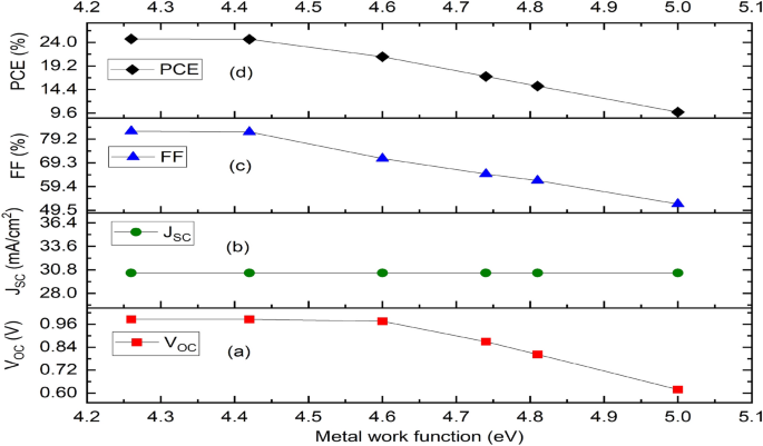
Effect of different back metal contact electrodes on parameters of the proposed IPSC. ( a ) Plot of V OC against metal work function, ( b ) Plot of J SC against metal work function, ( c ) Plot of FF against metal work function, ( d ) Plot of PCE against metal work function.
Effect of back contact electrode on the proposed inverted perovskite solar cell
Various metal back contact electrodes such as aluminium (4.26 eV), tin (4.42 eV) graphene (4.60 eV), silver (4.74 eV), iron (4.81 eV) and copper (5.00 eV) have been tested on the proposed inverted structure so as to determine the most appropriate one to be used for enhanced optimal performance. Figure 1 shows the work function of various metals used as back contact electrodes and their associated photovoltaic parameters on the proposed IPSC based device simulated using initial given parameters presented in Tables 1 and 2 . The results in Fig. 1 clearly show that the choice of aluminum (Al) for back electrode maintained the most optimal device performance, as the V oc , J SC , FF and PCE of 0.9854 V, 30.4185 mA/cm 2 , 82.48% and 24.72% respectively is produced. It is interesting to note in this model that the J SC (Fig. 1 b) remains constant as the work function of the back contact varies while the V OC , FF and PCE declines as the work function increases from 4.26 to 5.00 eV (Fig. 1 a,c,d). For p–n configuration, the current is negative because of the uphill diffusion of the minority charge carriers in terms of concentration gradient arising from reverse bias during solar illumination. The current growth from the negative quadrant towards the positive quadrant signifies power generation up to zero value of current where an open circuit voltage (V OC ) of 0.9854 V is achieved. The J–V characteristics of the device having used aluminum as the back contact electrode is shown as Fig. 2 .
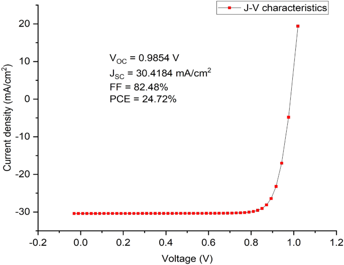
J–V Characteristics of the proposed inverted perovskite solar cell with initial parameters using MASnI 3 as absorber material, Cu 2 O as HTM, ZnO as ETM and Al as back contact respectively.
Effect of n-type TCO-free on inverted perovskite solar cell architecture.
There is no experimental result for this exact structure (Cu 2 O/CH 3 NH 3 SnI 3 /ZnO/Al) known to us, which makes this research novel and interesting. There is no clear reasons why the lack of experimental works to support this study, but this could be due to lack of good conductivity of all-inorganic transport materials in nano electronics compared to organic transport materials and high processing temperature required. However, there are few simulation results of exact combination in n–i–p structure reported in 63 , 64 . The PCEs of 26.55% and 9.27% respectively were obtained in 63 and 64 , while our designed n-type TCO-free p-i-n device produced a superior PCE of 30.17% as shown in Fig. 8 .
The proposed inverted model will not simulate when the conventional n-type TCO (ITO/FTO) of donor concentration ND is used with the acceptor concentration NA being zero, except an organic p-type TCO is used which is outside the scope of this study. It’s worth noting that the top transparent glass used as presented in Fig. 16 is an n-type TCO-free substrate in order to avoid non-convergence of voltage between the front and back electrodes when a conventional n-type TCOs are used. The carefully chosen transparent glass substrate size of 50 nm is not included in the simulation model, hence it is undoped and may not have significant impact on the device in real experimental situation. In this work, it is difficult to drive an output from the device if a TCO of an n-type material (FTO/ITO) is used as front electrode in the inverted structure when the same n-type material of same polarity is used as back hole blocker (ZnO) because of non-voltage convergence arising from non-compatible work function between the layers. The non-voltage convergence experienced when ITO with metal function of 4.7 eV is used is as a result of non-ideal band gap between the adjacent semiconductors layers (ITO/Cu 2 O) which makes the proposed n-type TCO-free model feasible. However, a back contact electrode of low metal function lower than ZnO like aluminium (4.26 eV) is required for optimal performance.
The use of Cu 2 O as front contact electrode may suffer setback due its high sheet resistance and poor conductivity when compared to n-type TCOs. However, the sheet resistance of most metal oxides depends on the method of deposition, temperature, oxygen flow rate and thickness of the films. The control of power and oxygen flow rates during deposition of copper oxide thin films at a thickness of less than 100 nm prepared by reactive magnetron sputtering can reduce the sheet resistance and enhance performance of the device in practical sense 65 . The provision of a high density of low energy sputtered copper radicals/ions, and when combined with a controlled amount of oxygen, can produce good quality p-type transparent Cu 2 O films with electrical resistivity ranging from 10 2 to 10 4 Ω-cm 66 which makes Cu 2 O a potential transparent front conducting oxide for photovoltaic applications. Also, the doping of Cu 2 O with nickel can improve its p–type conductivity via extrinsic doping and post–growth processing 67 . Therefore, the Cu 2 O may not be as conductive as other n-type TCOs in experimental sense but runs conveniently in the simulation model without challenge which means the proposed n-type TCO–free model is novel and less complex, providing good direction in the design and modeling of simple inverted perovskite solar cells as shown in Figs. 13 and 16 . Cu 2 O can act as a front electrode efficiently provided its thickness is thin enough to ensure adequate clarity and transparency to enhance admittance of photons into the absorber (perovskite) layer.
Effect of thickness of the HTM (Cu 2 O), absorber (CH 3 NH 3 SnI 3 ) and ETM (ZnO) layers
In this study, the variation of HTM’s layer thickness from 10 to 100 nm results to a slight increase in FF (Fig. 3 c) while a decline in device parameters such as V OC , J SC and PCE is experienced as presented in Fig. 3 a,b,d respectively.
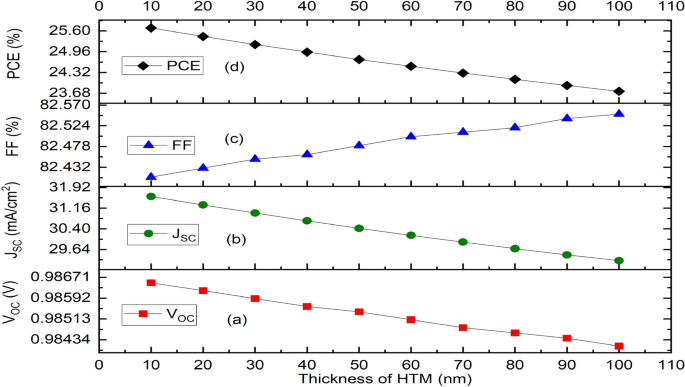
Effect of variation of thickness of the HTM layer (Cu 2 O) on solar cell parameters. ( a ) Plot of V OC against thickness, ( b ) Plot of J SC against thickness, ( c ) Plot of FF against thickness, ( d ) Plot of PCE against thickness.
The thickness of the absorber layer considerably affects the solar cell’s overall performance. The increase in absorber’s thickness decreases the V OC due to increase in series resistance. Meanwhile, the increase in absorber’s thickness increases the J SC, FF and PCE to the maximum after which it decreases with further increase in thickness. In this study, the thickness of CH 3 NH 3 SnI 3 has been adjusted in this simulation from 100 to 1500 nm. The fluctuation of photovoltaic characteristics with thickness of absorber layer is shown in Fig. 4 . The V OC declines as a result of faster recombination due to increased thickness (Fig. 4 a). A thicker absorber layer absorbs more photons, which increases short circuit current density (J CS ) and the fill factor (FF) and as seen in Fig. 4 b,c, respectively. The solar cell efficiency is increased as the thickness of absorber layer increases up to an ideal thickness for the solar cell after which efficiency declines (Fig. 4 d). However, as diffusion necessitates a longer charge travel distance, recombination is more common in larger absorber layers; hence, efficiency decreases after a certain thickness value. Our results concur with experimental findings in 62 , 68 . As shown in Fig. 4 d, the ideal absorber layer thickness for this inverted PSC is achieved between 1200 and 1300 nm.
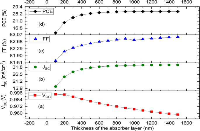
Effect of variation of thickness of the absorber layer (MASnI 3 ) on solar cell parameters. ( a ) Plot of V OC against thickness, ( b ) Plot of J SC against thickness, ( c ) Plot of FF against thickness, ( d ) Plot of PCE against thickness.
Nevertheless, the increase in ETM’s thickness leads to a non-noticeable change in V OC , J SC , FF and PCE (Fig. 5 a–d) respectively. Therefore, it can be inferred that while device performance is mostly determined by absorber thickness, IPSC device performance is not influenced by the ETM layer’s thickness but rather varies slightly with the HTM’s thickness, which is designed to be small enough to guarantee optical transparency and ensure easy photon penetration to the absorber layer. The selection of optimal thickness is important to regulate series and shunt resistance and ensure improved device performance in terms of short circuit current, open circuit voltage, fill factor and power conversion efficiency.
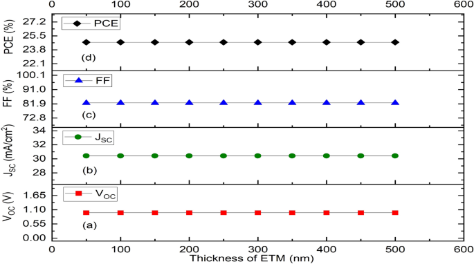
Effect of variation of thickness of the ETM layer (ZnO) on solar cell parameters. ( a ) Plot of V OC against thickness, ( b ) Plot of J SC against thickness, ( c ) Plot of FF against thickness, ( d ) Plot of PCE against thickness.
Simulation and thickness optimization of the proposed device structure
Simulation and optimization of the proposed device shows that the HTM (Cu 2 O) layer, the absorber (MASnI 3 ) layer and ETM layer (ZnO) have been optimized to the thickness of 40 nm, 1200 nm and 200 nm respectively. The simulation of these optimized dimensions led to an improvement in the solar cell parameters as it produced a Voc of 0.9633 V, J SC of 33.8049 mA/cm 2 , FF of 82.84% and PCE of 26.97% as shown in the J–V characteristics curve (Fig. 6 ).
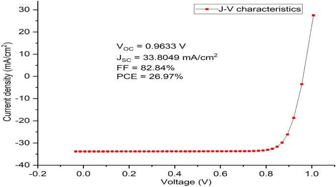
J–V characteristics of the optimized device’s thickness using MASnI 3 as absorber material, Cu 2 O as HTM, ZnO as ETM and Al as back contact respectively.
Effect of absorber’s doping concentration (NA)
The holes’ acceptor density of the absorber layer has a major impact on the photovoltaic cell’s device performance in addition to its thickness. As demonstrated in Fig. 7 , the Fermi energy level of the hole falls with increasing doping concentration of the acceptor, and as a result, V OC increases (Fig. 7 a). Also, an increase in the doping concentration of the acceptor leads to a built-in potential that increases charge separation, which in turn causes a rise in V OC . In this work, the acceptor concentration NA (1/cm 3 ) of the absorber layer is varied within a range of 3 × 10 14 cm −3 to 3 × 10 21 cm −3 to ascertain the most optimal value that can produce an optimal performance of the proposed device. Nevertheless, J SC maintains a steady decline marginally up to NA’s value of 3 × 10 19 cm −3 before falling off sharply. At the same NA’s value, the value of FF drops suddenly which might be caused by a rise in the rate at which charge carriers within the absorber layer recombine or an increase in series resistance 55 . The absorber layer’s doping concentration value of 3 × 10 19 cm −3 produced the best cell performance having V oc of 1.0867 V, J SC of 33.4942 mA/cm 2 , FF of 82.88% and PCE of 30.17% as shown in Fig. 7 a–d respectively, while its J–V characteristics is shown as Fig. 8 .
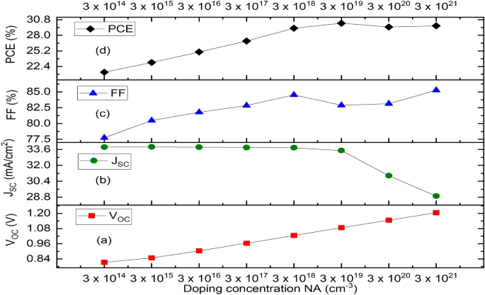
Effect of variation of doping concentration of the absorber (CH 3 NH 3 SnI 3 ) on solar cell parameters. ( a ) Plot of V OC against doping concentration (NA), ( b ) Plot of J SC against doping concentration (NA), ( c ) Plot of FF against doping concentration (NA), ( d ) Plot of PCE against doping concentration (NA).
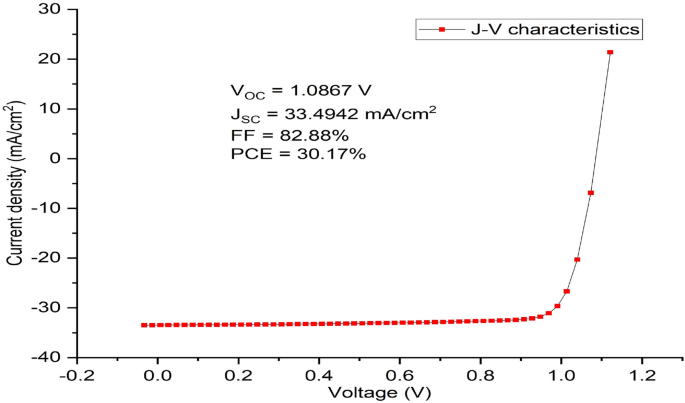
J–V Characteristics of the final optimized inverted simulated solar cell device using MASnI 3 as absorber material, Cu 2 O as HTM, ZnO as ETM and Al as back contact respectively.
The complex nature of an organic molecule in the A site of the perovskite structure (ABX 3 ) may be the cause of degradation, as evidenced by the absorber’s bandgap of 1.3 eV and the measured Voc of 1.0867 V. Using varying ratios of the precursors causes an intrinsic fault when the perovskite structure is distorted. Higher degrees of crystallization and a slower rate of breakdown are the results of vacancies in the structure caused by the excess CH 3 NH 3 I (MAI). The crystalline lattice’s anomalies emphasize the role MAI plays in the deterioration process. Excess MAI may potentially release halide ions, depending on the concentration. Afterwards, these halide ions function as dopants, altering the perovskite semiconductors' bandgap 69 . When exposed to air, the Sn 2+ in CH 3 NH 3 SnI 3 is changed to Sn 4+ (a process known as self-doping), converting the device into a p-type semiconductor. Sadly, this procedure deteriorates the device performance, such as the output power and the power conversion efficiency 56 , 70 .
Effect of series resistance R series and shunt resistance R shunt
The resistance in series and shunt (R series and R shunt ) affects the J–V curve’s form and slope, which in turn affects the solar cell’s efficiency. The connections electrodes, electrical dissipation in the perovskite, and layers of hole and electron transport materials (HTM and ETM) are primarily linked to the cause of the R series . However, different recombination pathways, device design, and defects induced during the layer deposition process are linked to the cause of the R shunt . According to the literature, a high shunt resistance and a low series resistance are necessary for a solar cell to have a high efficiency. Electrons cannot flow freely across a circuit if the series resistance is large, and leakage current will occur if the shunt resistance is low, producing PSCs with low stability and efficiency. When there’s a low shunt resistance or a high series resistance, the PSC’s maximum output and FF would both drop 71 , 72 . The ideal diode model’s Eq. ( 4 ) was applied in order to comprehend the impact of R series and R shunt on the perovskite solar cell’s performance 73 .
When \(J\approx\) 0 mA/cm 2 for open circuit state, the variables V OC and R shunt relationship is presented in Eq. ( 5 )
where J is the current flowing via the external circuit, V is the output voltage, A is the ideality factor, k is the Boltzmann constant, T is the temperature, q is the electron charge, J O is the saturation current density and J L is the light-induced current density. As a result, low R shunt reduces photovoltaic voltage and may also have an impact on the photocurrent that is collected, whereas high R series values primarily influence the FF and Jsc values 72 .
While keeping the other simulation parameters same, R series and R shunt were changed from 0 to 100 Ωcm 2 and 10 3 Ωcm 2 to 10 10 Ωcm 2 respectively, to better understand their influence on the J–V curves. The responses of V OC , J SC FF and PCE as a function of R series are presented in Fig. 9 . V OC stays fairly constant, J SC falls from 33.51 to 10.77 mA/cm 2 , and FF drops from 85.63 to 24.88% while R series grows from 0 to 100 Ωcm 2 . As a result, as Fig. 9 d illustrates, PCE’s behavior is precisely proportional to J SC and FF, decreasing from 31.16 to 2.91% for the same range. Alternatively, as Fig. 10 illustrates, when R shunt rises from 10 3 to 10 10 Ωcm 2 , V OC rises from 1.0858 to 1.0868 V, J SC maintains a constant 33.49 mA/cm 2 from 10 4 Ωcm 2 , FF rises from 80.75 to 83.12%, and the PCE rises from 29.34 to 30.26% respectively (Fig. 10 a–d). For R series and R shunt , the optimal values are therefore 1 Ωcm 2 and 10 6 Ωcm 2 respectively, which is in conformity with literature.
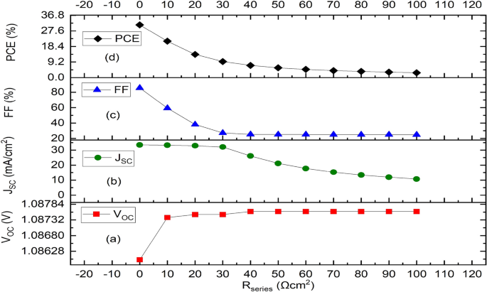
Effect of series resistance variation on the optimized IPSC based device parameters. ( a ) Plot of V OC against series resistance. ( b ) Plot of J SC against series resistance. ( c ) Plot of FF against series resistance, ( d ) Plot of PCE against series resistance.
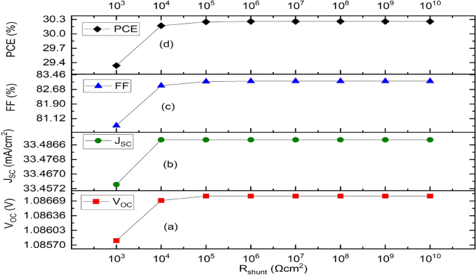
Effect of shunt resistance variation on parameters of the optimized IPSC device. ( a ) Plot of V OC against shunt resistance, ( b ) Plot of J SC against shunt resistance, ( c ) Plot of FF against shunt resistance, ( d ) Plot of PCE against shunt resistance.
Effect of the defect state of bulk and interface layers
The impact of the absorber’s defect density is an important factor that needs to be examined. In the absorber layer, defects are inevitable. Both at surfaces and in the bulk, they are present. Point defects in the perovskite absorber layer include lattice vacancies, interstitial, Schottky, and Frenkel defects. In addition, there may be higher order defects like grain boundaries and dislocations 74 . The self-doping process in the absorber layer creates the p-type semiconductor that results in an impurity defect 54 , 56 , 75 , 76 . These defects cause the energy bandgap to appear at shallow or deep levels 74 . Charge carriers have the ability to capture and promote nonradiative recombination of electron–hole as a result of these defects 53 , 55 . Noteworthy, the simulated interface defect density for both electron and hole recombination velocities was 1 × 10 -2 cm/s for both HTM/MASnI 3 and ETM/MASnI 3 interface. In the Sn-based perovskite absorber layer, the electron and hole diffusion lengths were 16 µm and 6.2 µm, respectively. The optimized device’s absorber defect density (Nt) of 2 × 10 15 cm −3 achieved a V OC of 1.0867 V, a J SC of 33.4942 mA/cm 2 , FF of 82.88%, and a PCE of 30.17%. Nevertheless, synthesizing a material with a low defect density value is a challenging task in an experiment 55 .
The Shockley–Read–Hall (SRH) recombination model has been applied to provide understanding regarding the impact of defect density in the absorber layer on device performance 49 , 53 , 77 . The effect of defect density on the recombination rate based on the SRH recombination model is essential to determining the critical influence of Nt on the device performance. The plot of recombination rate with depth from the optimized device’s surface is depicted in Fig. 11 .
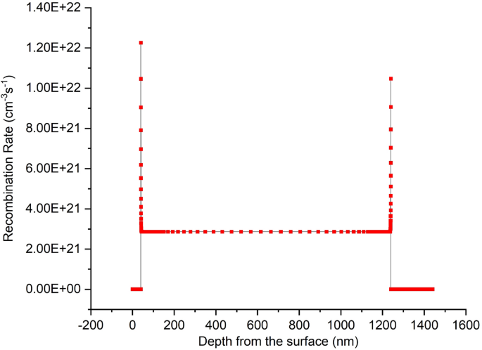
Recombination rate of the optimized device with depth from the surface.
The proposed device produced quantum efficiency curve covering the entire visible spectrum (300–900 nm) achieving an optimum quantum efficiency (QE) of 99.38% at 580 nm wavelength, which is in agreement with other works 15 , 43 , 54 , 61 , 78 , 79 is presented as Fig. 12 . The simulated inverted structure, energy band diagram, energy band alignment and complete device structure of the optimized inverted planar perovskite solar cells are presented as Figs. 13 , 14 , 15 and 16 , respectively. It’s very clear that the photovoltaic performance of the proposed device as shown in Table 3 is superior to other related works reported in the literature.
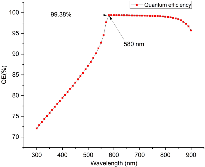
Quantum efficiency of the proposed inverted perovskite solar cell.
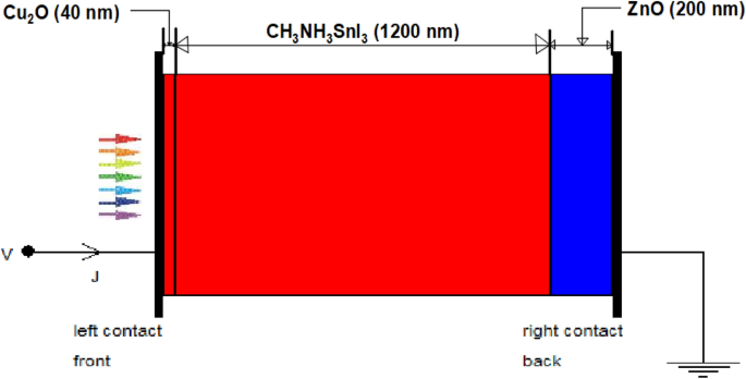
The simulated inverted device structure.
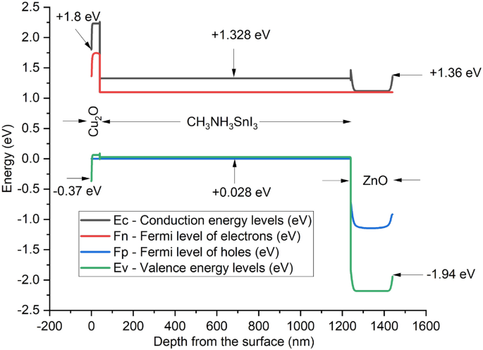
Energy band diagram of the proposed inverted perovskite solar cell.
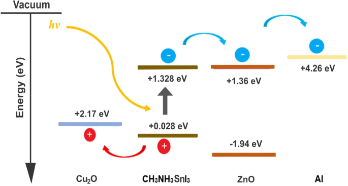
Energy band alignment profile of the proposed inverted perovskite solar cell.
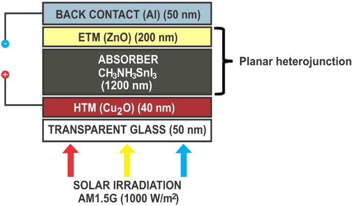
The complete optimized structure of the proposed n-type TCO-free inverted perovskite solar cell.
The toxic-free CH 3 NH 3 SnI 3 as light harvesting material is explored in this study. A heterojunction planar perovskite solar cell with an inverted structure Glass/Cu 2 O/CH 3 NH 3 SnI 3 /ZnO/Al was simulated, optimized and analyzed in this paper. In relation to various photovoltaic parameters such as the work function of the back contact electrodes, thickness of the HTM layer, absorber and the ETM layers, and the absorber’s doping concentration were optimized. The thickness of the HTM, absorber layer and ETM were optimized to 40 nm, 1200 nm and 200 nm respectively. The optimized structure produced an enhanced Voc of 1.0867 V, J SC of 33.4942 mA/cm 2 , FF of 82.88% and PCE of 30.17% respectively. The results indicate that an increase in doping concentration of the absorber increased the Voc, FF and PCE but decreased the J SC of the solar cell. The interface between the ETM/back-electrode requires a cheap and low work function metal for enhanced performance. The n-type TCO-free inverted CH 3 NH 3 SnI 3 -based PSC provides a potential path to attaining simple, eco-friendly, cheap and highly efficient perovskite solar cell device using all-inorganic transport materials.
Data availability
The data that support the findings can be made available upon reasonable request from the corresponding author on [email protected].
Danladi, E. et al. Impact of transport material on perovskite solar cells with different metal electrode: A SCAPS-1D Simulation insight. Heliyon. https://doi.org/10.1016/j.heliyon.2023.e16838 (2023).
Article PubMed PubMed Central Google Scholar
Saha, P., Singh, S. & Bhattacharya, S. Efficient and lead-free perovskite solar cells based on defect-ordered methyl ammonium antimony iodide. IEEE Trans. Electron. Devices 70 (3), 1095–1101. https://doi.org/10.1109/TED.2023.3235870 (2023).
Article ADS CAS Google Scholar
Bhattarai, S. et al. Carrier transport layer free perovskite solar cell for enhancing the efficiency: A simulation study. Opt. Int. J. Light Electron. Opt. 243 , 167492. https://doi.org/10.1016/j.ijleo.2021.167492 (2021).
Article CAS Google Scholar
Celik, I. et al. Environmental analysis of perovskites and other relevant solar cell technologies in a tandem configuration. Energy Environ. Sci. 10 , 1874–1184. https://doi.org/10.1039/c7ee01650f (2017).
Lhoussayne, E. et al. Numerical analysis of earth-abundant Cu 2 ZnSn(S x Se 1 − x ) 4 solar cells based on Spectroscopic Ellipsometry results by using SCAPS-1D. Solar Energy. 201 , 827–835. https://doi.org/10.1016/j.solener.2020.03.070 (2020).
Battaglia, C., Cuevas, A. & Wolf, S. D. High-efficiency crystalline silicon solar cells: Status and perspectives. Energy Environ. Sci. 9 , 1552–1576. https://doi.org/10.1039/C5EE03380B (2016).
Major, J. D. Grain boundaries in CdTe thin film solar cells: A review. Semicond. Sci. Technol. 31 , 093001. https://doi.org/10.1088/0268-1242/31/9/093001 (2016).
Basol, B. M. & McCandless, B. Brief review of cadmium telluride-based photovoltaic technologies. J. Photon. Energy. 4 (1), 040996. https://doi.org/10.1117/1.JPE.4.040996 (2016).
Article Google Scholar
Carey, G. H. et al. Colloidal quantum dot solar cells. Chem. Rev. 115 (23), 12732–12763. https://doi.org/10.1021/acs.chemrev.5b00063 (2015).
Article ADS CAS PubMed Google Scholar
Ramanujam, J. & Singh, U. P. Copper indium gallium selenide based solar cells—A review. Energy Environ. Sci. 10 , 1306–1319. https://doi.org/10.1039/C7EE00826K (2017).
Feurer, T. et al. Progress in thin film CIGS photovoltaics—Research and development, manufacturing, and applications. Progress Photovolt. Res. Appl. 25 (7), 645–667. https://doi.org/10.1002/pip.2811 (2017).
Lu, L. Y. et al. Recent advances in bulk heterojunction polymer solar cells. Chem. Rev. 115 (23), 12666–12731. https://doi.org/10.1021/acs.chemrev.5b00098 (2015).
Saparov, B. & Mitzi, D. B. Organic–inorganic perovskites: Structural versatility for functional materials design. Chem. Rev. 116 (7), 4558–4596. https://doi.org/10.1021/acs.chemrev.5b00715 (2016).
Article CAS PubMed Google Scholar
Pandey, R. et al. Halide composition engineered a non-toxic perovskite−silicon tandem solar cell with 30.7% conversion efficiency. ACS Appl. Electron. Mater. 5 , 5303–5315. https://doi.org/10.1021/acsaelm.2c01574 (2023).
Bhattarai, S. et al. Comparative study of distinct halide composites for highly efficient cesium-based perovskite solar cells. Energy Fuels. 37 , 16035–16049. https://doi.org/10.1021/acs.energyfuels.3c02610 (2023).
Durodola, O. M., Ugwu, C. & Danladi, E. Highly efficient lead-free perovskite solar cell based on Magnesium-doped copper delafossite hole transport layer: A SCAPS-1D framework prospect. Emerg. Mater. 100 , 101001. https://doi.org/10.1016/j.jics.2023.101001 (2023).
Hartono, N. T. P. et al. Stability follows efficiency based on the analysis of a large perovskite solar cells ageing dataset. Nat. Commun. 14 , 4869. https://doi.org/10.1038/s41467-023-40585-3 (2023).
Article ADS CAS PubMed PubMed Central Google Scholar
Kim, H. S., Im, S. H. & Park, N. G. Organolead halide perovskite: New horizons in solar cell research. J. Phys. Chem. C 118 , 5615–5625. https://doi.org/10.1021/jp409025w (2014).
Lyu, M. et al. Addressing toxicity of lead: Progress and applications of low-toxic metal halide perovskites and their derivatives. Adv. Energy Mater. 7 , 1602512–1602537. https://doi.org/10.1002/aenm.201602512 (2017).
Burschka, J. et al. Sequential deposition as a route to high-performance perovskite-sensitized solar cells. Nature 499 , 316–319. https://doi.org/10.1038/nature12340 (2013).
Lee, M. M. et al. Efficient hybrid solar cells based on meso-superstructured organometal halide perovskites. Science 338 (6107), 643–647. https://doi.org/10.1126/science.1228604 (2012).
Bhattarai, S. et al. Performance improvement approach of all inorganic perovskite solar cell with numerical simulation. Mater. Today Commun. 33 , 104364. https://doi.org/10.1016/j.mtcomm.2022.104364 (2022).
Saha, P. et al. Optimization and formulation of different hole-transporting materials (HTMs) for the performance of eco-friendly Cs 2 TiBr 6 —Based perovskite solar cells. Energy Technol. https://doi.org/10.1002/ente.202300991 (2024).
Saha, P., Singh, S. & Bhattacharya, S. Eco-friendly methyl-ammonium tin-based planar p–n homojunction Perovskite solar cells: Design and performance estimation. Int. J. Modern Phys. B 37 (17), 22350169. https://doi.org/10.1142/S0217979223501692 (2023).
Huang, H. H. et al. Boosting the ultra-stable unencapsulated perovskite solar cells by using montmorillonite/CH 3 NH 3 PbI 3 nanocomposite as photoactive layer. Energy Environ. Sci. 12 , 1265–1273. https://doi.org/10.1039/C8EE02958J (2019).
Liu, D. et al. Predicted photovoltaic performance of lead-based hybrid perovskites under the influence of a mixed-cation approach: Theoretical insights. J. Mater. Chem. C 7 , 371–379. https://doi.org/10.1039/C8TC04065F (2019).
Santosa, I. M. D. L. et al. Optimization of CH 3 NH 3 PbI 3 perovskite solar cells: A theoretical and experimental study. Solar Energy 199 , 198–205. https://doi.org/10.1016/j.solener.2020.02.026 (2020).
Li, X. et al. Low-temperature solution processed ZnSe electron transport layer for efficient planar perovskite solar cells with negligible hysteresis and improved photostability. ACS Nano 12 (6), 5605–5614. https://doi.org/10.1021/acsnano.8b01351 (2018).
Article MathSciNet CAS PubMed Google Scholar
El-Mellouhi, F. et al. Hydrogen bonding and stability of hybrid organic–inorganic perovskites. ChemSusChem 9 , 2648–2655. https://doi.org/10.1002/cssc.201600864 (2016).
El-Mellouhi, F. et al. Enhancing intrinsic stability of hybrid perovskite solar cell by strong, yet balanced, electronic coupling. Sci. Rep. 6 , 30305. https://doi.org/10.1038/srep30305 (2016).
Wang, Q. et al. Enhancement in lifespan of halide perovskite solar cells. Energy Environ. Sci. 12 , 865–886. https://doi.org/10.1039/C8EE02852D (2019).
Zhao, Z. et al. Metal halide perovskite materials for solar cells with long-term stability. Adv. Energy Mater. 9 , 1802671. https://doi.org/10.1002/aenm.201802671 (2019).
Chen, B. et al. Origin of J–V hysteresis in perovskite solar cells. J. Phys. Chem. Lett. 7 , 905–917. https://doi.org/10.1021/acs.jpclett.6b00215 (2016).
Chen, H. & Yang, S. Carbon-based perovskite solar cells without hole transport materials: The front runner to the market. Adv. Mater. 29 (24), 1603994. https://doi.org/10.1002/adma.201603994 (2017).
Jung, M. C. et al. Substantial improvement of perovskite solar cells stability by pinhole-free hole transport layer with doping engineering. Sci. Rep. 5 , 9863. https://doi.org/10.1038/srep09863 (2015).
Article CAS PubMed PubMed Central Google Scholar
Rahman, S., et al . Simulation based investigation of inverted planar perovskite solar cell with all metal oxide inorganic transport layers. In Proceedings of the 2019 International Conference on Electrical, Computer and Communication Engineering (ECCE) , Cox’s Bazar, Bangladesh, 7–9 February 2019. document/8679283.
Shubhranshu, B. et al. Performance of WO 3 -incorporated carbon electrodes for ambient mesoscopic perovskite solar cells. ACS Omega 5 (1), 422–429. https://doi.org/10.1021/acsomega.9b02934 (2020).
Asad, J. et al. Perovskite solar cells free of hole transport layer. J. Sol–Gel Sci. Technol. 90 , 443–449. https://doi.org/10.1007/s10971-019-04957-w (2019).
Wang, T. et al. Optimal design of efficient hole transporting layer free planar perovskite solar cell. Sci. China Mater. 59 , 703–709. https://doi.org/10.1007/s40843-016-5108-4 (2016).
Xiaonan, H. et al. Preparation of high-efficiency (>14%) HTL-free carbon-based all-inorganic perovskite solar cells by passivation with PABr derivatives. ACS Appl. Mater. Interfaces 15 (7), 9382–9391. https://doi.org/10.1021/acsami.2c21226 (2023).
Ono, L. K. et al. The absence of pinholes in HTM significantly improves the stability of perovskite solar cells under operating conditions. J. Mater. Chem. A 3 , 15451–15456. https://doi.org/10.1039/C5TA03443D (2015).
Príncipe, J., Duarte, V. C. M. & Andrade, L. Inverted perovskite solar cells: The emergence highly stable and efficient architecture. Energy Technol. 10 , 2100952. https://doi.org/10.1002/ente.202100952 (2022).
Fakhri, N. et al. Simulation of perovskite solar cells optimized by the inverse planar method in SILVACO: 3D electrical and optical models. Energies 14 , 5944. https://doi.org/10.3390/en14185944 (2021).
Liu, J. et al. HClO 4 -assisted fabrication of SnO 2 /C 60 bilayer electron-transport materials for all air-processed efficient and stable inverted planar perovskite solar cells. J. Power Sources. 476 , 228648. https://doi.org/10.1016/j.jpowsour.2020.228648 (2020).
Li, T. et al. Multiple functional groups synergistically improve the performance of inverted planar perovskite solar cells. J. Nano Energy. 82 , 105742. https://doi.org/10.1016/j.nanoen.2021.105742 (2021).
He, Y. et al. Enhanced efficiency and stability of inverted planar perovskite solar cells with piperazine as an efficient dopant into PCBM. IEEE J. Photovolt. 10 , 811–817. https://doi.org/10.1109/JPHOTOV.2020.2974803 (2020).
Lan, F., Jiang, M., Tao, Q. & Li, G. Revealing the working mechanisms of planar perovskite solar cells with cross-sectional surface potential profiling. IEEE J. Photovolt. 8 , 125–131. https://doi.org/10.1109/JPHOTOV.2017.2762525 (2017).
Abdul, S., et al . Performance Evaluation of Solar Cells by Different Simulating Softwares . Vol. 7, pp. 1–21 (2023). https://doi.org/10.5772/intechopen.111639 .
Lin, L. et al. A modelled perovskite solar cell structure with a Cu 2 O hole-transporting layer enabling over 20% efficiency by low-cost low-temperature processing. J. Phys. Chem. Solids. 14 , 205–211. https://doi.org/10.1016/j.jpcs.2018.09.024 (2019).
Song, L., Yong-Li, C., Wen-Hua, L. & Zhi-Shan, B. A brief review of hole transporting materials commonly used in perovskite solar cells. Rare Met. 40 (10), 2712–2729. https://doi.org/10.1007/s12598-020-01691-z (2021).
Bhattarai, S. & Das, T. D. Optimization of carrier transport materials for the performance enhancement of the MAGeI 3 based perovskite solar cell. Solar Energy. 217 , 200–207. https://doi.org/10.1016/j.solener.2021.02.002 (2021).
Saha, P., Singh, S. & Bhattacharya, S. FASnI 3 -based eco-friendly heterojunction perovskite solar cell with high efficiency. Micro Nanostruct. 186 , 207739. https://doi.org/10.1016/j.micrna.2023.207739 (2024).
Lazemi, M., Asgharizadeh, S. & Bellucci, S. A computational approach to interface engineering of lead-free CH 3 NH 3 SnI 3 highly-efficient perovskite solar cells. Phys. Chem. Chem. Phys. 20 (40), 25683–25692. https://doi.org/10.1039/C8CP03660H (2018).
Hao, F. et al. Lead-free solid-state organic–inorganic halide perovskite solar cells. Nature Photon. 8 , 489–494. https://doi.org/10.1038/nphoton.2014.82 (2014).
Du, H. J., Wang, W. C. & Zhu, J. Z. Device simulation of lead-free CH 3 NH 3 SnI 3 perovskite solar cells with high efficiency. Chin. Phys. B. 25 , 108802–188809. https://doi.org/10.1088/1674-1056/25/10/108802 (2016).
Ma, L. et al. Carrier diffusion lengths of over 500 nm in lead-free perovskite CH 3 NH 3 SnI 3 films. J. Am. Chem. Soc. 138 , 14750–14755. https://doi.org/10.1021/jacs.6b09257 (2016).
Stoumpos, C. C., Malliakas, C. D. & Kanatzidis, M. G. Semiconducting tin and lead iodide perovskites with organic cations: Phase transitions, high mobilities, and near-infrared photoluminescent properties. Inorg. Chem. 52 , 9019–9038. https://doi.org/10.1021/ic401215x (2013).
Devi, C. & Mehra, R. Device simulation of lead-free MASnI3 solar cell with CuSbS 2 (copper antimony sulfide). J. Mater. Sci. 54 , 5615–5624. https://doi.org/10.1007/s10853-018-03265-y (2019).
Khattak, Y. H., Baig, F., Toura, H., Beg, S. & Soucase, B. M. CZTSe kesterite as an alternative hole transport layer for MASnI 3 perovskite solar cells. J. Electron. Mater. 48 , 5723–5733. https://doi.org/10.1007/s11664-019-07374-5 (2019).
Constantinos, C. et al. Semiconducting tin and lead iodide perovskites with organic cations: Phase Transitions, high mobilities, and near-infrared photoluminescent properties. Org. Chem. 52 , 9019–9038. https://doi.org/10.1021/ic401215x (2013).
Patel, P. K. Device simulation of highly efficient eco-friendly CH 3 NH 3 SnI 3 perovskite solar cell. Sci. Rep. 11 , 3082. https://doi.org/10.1038/s41598-021-82817-w (2021).
Shamna, M. S., Nithya, K. S. & Sudheer, K. S. Simulation and optimization of CH 3 NH 3 SnI 3 based inverted perovskite solar cell with NiO as hole transport material. Mater. Today Proc. 33 (2), 1246–1251. https://doi.org/10.1016/j.matpr.2020.03.488 (2020).
Manisha Ahamad, A. K. M. & Hossain, A. Design and optimization of non-toxic and highly efficient tin-based organic perovskite solar cells by device simulation. Heliyon 9 , e19389. https://doi.org/10.1016/j.heliyon.2023.e19389 (2023).
Tareq, D.E., et al . Perovskite solar cells based on CH 3 NH 3 SnI 3 structure. In 2nd International Scientific Conference of Al-Ayen University (ISCAU-2020), IOP Conf. Series: Materials Science and Engineering vol. 928, 072148 (2020). https://doi.org/10.1088/1757-899X/928/7/072148 .
Ogwu, A. A. et al. Electrical resistivity of copper oxide thin films prepared by reactive magnetron. J. Ach. Mater. Manuf. Eng. 24 , 171–177 (2007).
Google Scholar
Li, F. M. et al. Low temperature (b100 °C) deposited P-type cuprous oxide thin films: Importance of controlled oxygen and deposition energy. Thin Solid Films 520 , 1278–1284. https://doi.org/10.1016/j.tsf.2011.04.192 (2011).
Wang, Y. et al. Improving the P-type conductivity of Cu 2 O thin films by Ni doping and their heterojunction with N–Zno. Appl. Surf. Sci. 590 , 153047. https://doi.org/10.1016/j.apsusc.2022.153047 (2022).
Correa-Baena, J. P. et al. Unbroken perovskite: Interplay of morphology, electro-optical properties, and ionic movement. Adv. Mater. 28 , 5031–5037. https://doi.org/10.1002/adma.201600624 (2016).
Rahimi, F. et al. Methylammonium iodide and its effect as an intrinsic defect in perovskite structure and device performance. Org. Electron. 62 , 304–310. https://doi.org/10.1016/j.orgel.2018.08.025 (2018).
Cao, H. et al. The effect of defects in tin-based perovskites and their photovoltaic devices. Mater. Today Phys. 21 , 100513. https://doi.org/10.1016/j.mtphys.2021.100513 (2021).
Kim, D. I. et al. A high-efficiency and stable perovskite solar cell fabricated in ambient air using a polyaniline passivation layer. Sci. Rep. 12 , 697. https://doi.org/10.1038/s41598-021-04547-3 (2022).
Karthick, S., Velumani, S. & Bouclé, J. Experimental and SCAPS simulated formamidinium perovskite solar cells: A comparison of device performance. Solar Energy. 205 , 349–357. https://doi.org/10.1016/j.solener.2020.05.041 (2020).
Li, Y. et al. Ultra-high open-circuit voltage of perovskite solar cells induced by nucleation thermodynamics on rough substrates. Sci. Rep. 7 , 46141. https://doi.org/10.1038/srep46141 (2017).
Lee, Y. M. et al. Comprehensive understanding and controlling the defect structures: An effective approach for organic–inorganic hybrid perovskite-based solar-cell application. Front. Energy Res. 6 , 1–9. https://doi.org/10.3389/fenrg.2018.00128 (2018).
Noel, N. K. et al. Lead-free organic–inorganic tin halide perovskites for photovoltaic applications. Energy Environ. Sci. 7 , 3061–3068. https://doi.org/10.1039/C4EE01076K (2014).
Hao, F. et al. Solvent-mediated crystallization of CH 3 NH 3 SnI 3 films for heterojunction depleted perovskite solar cells. J. Am. Chem. Soc. 137 , 11445–11452. https://doi.org/10.1021/jacs.5b06658 (2015).
Haider, S. Z., Anwar, H. & Wang, M. A. comprehensive device modelling of perovskite solar cell with inorganic copper iodide as hole transport material. Semicond. Sci. Technol. 33 (3), 035001–035012. https://doi.org/10.1088/1361-6641/aaa596 (2018).
Odari, V. et al. Device simulation of SB2S3 solar cells by SCAPS-1D software. Africa J. Phys. Sci. 3 , 39–54 (2019).
Totohua, E. P. Numerical simulation of an inverted perovskite solar cell using a SiOx layer as down-conversion energy material to improve efficiency and stability. Materials 16 , 7445. https://doi.org/10.3390/ma16237445 (2023).
Farhana, A., Rafee, M., Sakin, S. S. & Saeed, M. U. Effects of different HTM layers and electrical parameters on ZnO nanorod-based lead-free perovskite solar cell for high-efficiency performance. Int. J. Photoenergy. https://doi.org/10.1155/2017/9846310 (2017).
Danladi, E. et al. Optimization of absorber and ETM layer thickness for enhanced tin based perovskite solar cell performance using SCAPS-1D software. Phys. Access. 2 (1), 1–11. https://doi.org/10.47514/phyaccess.2022.2.1.001 (2022).
Hao, L. et al. A tin-based perovskite solar cell with an inverted hole-free transport layer to achieve high energy conversion efficiency by SCAPS device simulation. Opt. Quantum Electron. 53 , 524. https://doi.org/10.1007/s11082-021-03175-5 (2021).
Banihashemi, M. Simulation of an inverted perovskite solar cell with inorganic electron and hole transfer layers. J. Photon. Energy 2 , 022001. https://doi.org/10.1117/1.JPE.7.022001 (2017).
Gong, J., & Krishnan, S.. Simulation of inverted perovskite solar cells. In Proceedings of the ASME 2018 12th International Conference on Energy Sustainability . June 24–28, 2018, Lake Buena Vista, FL, USA. https://doi.org/10.1115/ES2018-7227 .
Aseena, S. et al. Solution-synthesized Cu 2 O as a hole transport layer for a ZnO-based planar heterojunction perovskite solar cells fabricated at room temperature. J. Electron. Mater. 51 , 1692–1699. https://doi.org/10.1007/s11664-022-09442-9 (2022).
Download references
Acknowledgements
The authors are very grateful to Dr. Marc Burgelman of the University of Gent in Belgium for providing the SCAPS-1D simulation program.
This work did not receive any funding support.
Author information
Authors and affiliations.
Department of Electrical and Electronics Engineering, University of Benin, Benin City, Nigeria
Emmanuel A. Nyiekaa, Timothy A. Aika & Patience E. Orukpe
Department of Physics, Federal University of Health Sciences, Otukpo, Nigeria
Eli Danladi
Department of Chemical Engineering, University of Benin, Benin City, Nigeria
Christopher E. Akhabue
Department of Electrical and Electronics Engineering, Joseph Sarwuan Tarka University, Makurdi, Nigeria
Emmanuel A. Nyiekaa
You can also search for this author in PubMed Google Scholar
Contributions
EAN conceived the idea, design, simulate and also carry out the writing and typesetting of the manuscript. TAA sourced for review materials used in the manuscript and preparation of figures. ED screened the review materials and identified relevant literatures and generation of data used in the manuscript. CEA and PEO supervised, edit the manuscript and made corrections accordingly.
Corresponding author
Correspondence to Emmanuel A. Nyiekaa .
Ethics declarations
Competing interests.
The authors declare no competing interests.
Additional information
Publisher's note.
Springer Nature remains neutral with regard to jurisdictional claims in published maps and institutional affiliations.
Rights and permissions
Open Access This article is licensed under a Creative Commons Attribution 4.0 International License, which permits use, sharing, adaptation, distribution and reproduction in any medium or format, as long as you give appropriate credit to the original author(s) and the source, provide a link to the Creative Commons licence, and indicate if changes were made. The images or other third party material in this article are included in the article's Creative Commons licence, unless indicated otherwise in a credit line to the material. If material is not included in the article's Creative Commons licence and your intended use is not permitted by statutory regulation or exceeds the permitted use, you will need to obtain permission directly from the copyright holder. To view a copy of this licence, visit http://creativecommons.org/licenses/by/4.0/ .
Reprints and permissions
About this article
Cite this article.
Nyiekaa, E.A., Aika, T.A., Danladi, E. et al. Simulation and optimization of 30.17% high performance N-type TCO-free inverted perovskite solar cell using inorganic transport materials. Sci Rep 14 , 12024 (2024). https://doi.org/10.1038/s41598-024-62882-7
Download citation
Received : 06 April 2024
Accepted : 22 May 2024
Published : 26 May 2024
DOI : https://doi.org/10.1038/s41598-024-62882-7
Share this article
Anyone you share the following link with will be able to read this content:
Sorry, a shareable link is not currently available for this article.
Provided by the Springer Nature SharedIt content-sharing initiative
- SCAPS-1D software
- Perovskite solar cell
- Hole transport layer
- Light absorber
- Electron transport layer
By submitting a comment you agree to abide by our Terms and Community Guidelines . If you find something abusive or that does not comply with our terms or guidelines please flag it as inappropriate.
Quick links
- Explore articles by subject
- Guide to authors
- Editorial policies
Sign up for the Nature Briefing newsletter — what matters in science, free to your inbox daily.
An official website of the United States government
The .gov means it’s official. Federal government websites often end in .gov or .mil. Before sharing sensitive information, make sure you’re on a federal government site.
The site is secure. The https:// ensures that you are connecting to the official website and that any information you provide is encrypted and transmitted securely.
- Publications
- Account settings
Preview improvements coming to the PMC website in October 2024. Learn More or Try it out now .
- Advanced Search
- Journal List
- Materials (Basel)

Photovoltaic Cell Generations and Current Research Directions for Their Development
Associated data.
Not applicable.
The purpose of this paper is to discuss the different generations of photovoltaic cells and current research directions focusing on their development and manufacturing technologies. The introduction describes the importance of photovoltaics in the context of environmental protection, as well as the elimination of fossil sources. It then focuses on presenting the known generations of photovoltaic cells to date, mainly in terms of the achievable solar-to-electric conversion efficiencies, as well as the technology for their manufacture. In particular, the third generation of photovoltaic cells and recent trends in its field, including multi-junction cells and cells with intermediate energy levels in the forbidden band of silicon, are discussed. We also present the latest developments in photovoltaic cell manufacturing technology, using the fourth-generation graphene-based photovoltaic cells as an example. An extensive review of the world literature led us to the conclusion that, despite the appearance of newer types of photovoltaic cells, silicon cells still have the largest market share, and research into ways to improve their efficiency is still relevant.
1. Introduction
Concerns about climate change and the increase in demand for electricity due to, among other things, an ever-growing population, necessitate efforts to move away from conventional methods of energy production. Rising carbon dioxide levels in the atmosphere caused by the use of fossil fuels is one of the factors causing ongoing climate change. Switching to renewable energy will produce energy with a smaller environmental footprint compared to fossil fuel sources. We are able to harness the full potential of sunlight energy to develop the best possible energy harvesting technologies capable of converting solar energy into electricity [ 1 ].
The currently used solar energy is very marginal—0.015% is used for electricity production, 0.3% for heating, and 11% is used in the natural photosynthesis of biomass. In contrast, about 80–85% of global energy needs are met by fossil fuels. The difficulty with fossil fuels is that their resources are limited and hostile to the environment due to their CO 2 emissions. For instance, for every ton of coal burned, one ton of carbon dioxide is released into the atmosphere. This emitted carbon dioxide is toxic to the environment and is a primary cause of global warming, the greenhouse effect, climate change, and ozone depletion [ 2 ].
The necessity of finding new renewable energy forms is extremely relevant and urgent today. That is why mankind must find alternative sources of energy to provide a clean and sustainable future. Within this context, solar energy is the best option among all alternative renewable energy sources due to its widespread accessibility, universality, and eco-friendly nature [ 3 ].
The most common metric used to evaluate the performance of photovoltaic technologies is conversion efficiency, which expresses the ratio of solar energy input to electrical energy output. The efficiency combines multiple component characteristics of the system, such as short-circuit current, open-circuit voltage, and fill factor, which in turn are dependent upon basic material features and manufacturing defects [ 4 ].
The cost-effectiveness of making a photovoltaic cell and its efficiency depend on the material from which it is made. Much research in this field has been carried out to find the material that is the most efficient and cost-effective for building photovoltaic cells. The specifications for an ideal material for PV solar cells include the following [ 5 ]:
- The cells are expected to have a band gap between 1.1 and 1.7 eV;
- Should have a direct band structure;
- Need to be easily accessible and non-toxic; and
- Should have high photovoltaic conversion efficiency [ 5 ].
A key problem in the area of photovoltaic cell development is the development of methods to achieve the highest possible efficiency at the lowest possible production cost. Improving the efficiency of solar cells is possible by using effective ways to reduce the internal losses of the cell. There are three basic types of losses: optical, quantum, and electrical, which have different sources of origin. Reducing losses of any kind requires different, often advanced, methods of cell manufacturing and photovoltaic module production. An upper efficiency limit for commercially accessible technologies is determined by the well-known Shockley–Queisser (SQ) limit, taking into account the balance between photogeneration and radiative recombination [ 6 ].
However, the greatest potential lies in the ability to reduce quantum losses, as they are intimately connected with the material properties and internal structure of the cell. Relevant here is the concept of band gap, which defines the minimum required energy of a photon incident onto the cell surface for it to take part in the photovoltaic conversion process. There is a relationship between the efficiency of the cell and the value of the band gap, which in turn is highly dependent on the material from which the photovoltaic cell is made. The basic, commonly used material for solar cells is silicon, which has a band gap value of about 1.12 eV, but by introducing modifications in its crystal structure, the physical properties of the material, especially the band gap width, can be affected [ 7 ].
The dominant loss mechanisms in conventional photovoltaic cells are the inability to absorb photons below the band gap and the thermalization of solar photons with energies above the band gap energy. Third-generation solar cell concepts have been proposed to address these two loss mechanisms in an attempt to improve solar cell performance. These solutions aim to exploit the entire spectrum by incorporating novel mechanisms to create new electron–hole pairs [ 8 ].
Major development potential among these concepts for improving the power generation efficiency of solar cells made of silicon is shown by the idea of cells whose basic feature is an additional intermediate band in the band gap model of silicon. It is located between the conduction band and the valence band, and its function is to allow the absorption of photons with energies below the width of the energy gap, resulting in higher quantum efficiency (a higher number of excited electrons in relation to the number of photons incident onto the surface of the cell) [ 9 ]. Currently, many directions of research development on the introduction of intermediate bands in semiconductors can be identified. One of them is the use of ion implantation, where two methods can be distinguished: introduction of dopants with extremely high concentrations to the substrate of the semiconductor, and implantation of the layer of silicon with high-dose metal ions [ 10 ].
The improvement of solar cell efficiency involves reducing various types of losses affecting the resultant cell efficiency. The National Renewable Energy Laboratory (NREL) runs a compilation of the highest verified research cell conversion efficiencies for different photovoltaic technologies, compiled from 1976 to the present ( Figure 1 ). Cell efficiency results are given for each semiconductor family: multi-junction cells; gallium arsenide single-junction cells; crystalline silicon cells; thin film technologies; emerging photovoltaic technologies. The latest world record for an individual technology is indicated by a flag across the right edge containing the efficiency and technology symbol [ 11 ].

NREL Best Research-Cell Efficiencies chart [ 11 ].
Photovoltaic cells can be categorized by four main generations: first, second, third, and fourth generation. The details of each are discussed in the next section.
2. Photovoltaic Cell Generations
In the past decade, photovoltaics have become a major contributor to the ongoing energy transition. Advances relating to materials and manufacturing methods have had a significant role behind that development. However, there are still numerous challenges before photovoltaics can provide cleaner and low-cost energy. Research in this direction is focused on efficient photovoltaic devices such as multi-junction cells, graphene or intermediate band gap cells, and printable solar cell materials such as quantum dots [ 12 ].
The primary role of a photovoltaic cell is to receive solar radiation as pure light and transform it into electrical energy in a conversion process called the photovoltaic effect. There are several technologies involved with the manufacturing process of photovoltaic cells, using material modification with different photoelectric conversion efficiencies in the cell components. Due to the emergence of many non-conventional manufacturing methods for fabricating functioning solar cells, photovoltaic technologies can be divided into four major generations, which is shown in Figure 2 [ 13 ].

Various solar cell types and current developments within this field [ 14 ].
The generations of various photovoltaic cells essentially tell the story of the stages of their past evolution. There are four main categories that are described as the generations of photovoltaic technology for the last few decades, since the invention of solar cells [ 15 ]:
- First Generation: This category includes photovoltaic cell technologies based on monocrystalline and polycrystalline silicon and gallium arsenide (GaAs).
- Second Generation: This generation includes the development of first-generation photovoltaic cell technology, as well as the development of thin film photovoltaic cell technology from “microcrystalline silicon (µc-Si) and amorphous silicon (a-Si), copper indium gallium selenide (CIGS) and cadmium telluride/cadmium sulfide (CdTe/CdS) photovoltaic cells”.
- Third Generation: This generation counts photovoltaic technologies that are based on more recent chemical compounds. In addition, technologies using nanocrystalline “films,” quantum dots, dye-sensitized solar cells, solar cells based on organic polymers, etc., also belong to this generation.
- Fourth Generation: This generation includes the low flexibility or low cost of thin film polymers along with the durability of “innovative inorganic nanostructures such as metal oxides and metal nanoparticles or organic-based nanomaterials such as graphene, carbon nanotubes and graphene derivatives” [ 15 ].
Examples of solar cell types for each generation along with average efficiencies are shown in Figure 3 .

Examples of photovoltaic cell efficiencies [ 16 ].
2.1. First Generation of Photovoltaic Cells
Silicon-based PV cells were the first sector of photovoltaics to enter the market, using processing information and raw materials supplied by the industry of microelectronics. Solar cells based on silicon now comprise more than 80% of the world’s installed capacity and have a 90% market share. Due to their relatively high efficiency, they are the most commonly used cells. The first generation of photovoltaic cells includes materials based on thick crystalline layers composed of Si silicon. This generation is based on mono-, poly-, and multicrystalline silicon, as well as single III-V junctions (GaAs) [ 17 , 18 ].
Comparison of first-generation photovoltaic cells [ 18 ]:
- Solar cells based on monocrystalline silicon (m-si)
Efficiency : 15 ÷ 24%; Band gap : ~1.1 eV; Life span : 25 years; Advantages : Stability, high performance, long service life; Restrictions : High manufacturing cost, more temperature sensitivity, absorption problem, material loss.
- Solar cells based on polycrystalline silicon (p-si)
Efficiency : 10 ÷ 18%; Band gap : ~1.7 eV; Life span : 14 years; Advantages : Manufacturing procedure is simple, profitable, decreases the waste of silicon, higher absorption compared to m-si; Restrictions : Lower efficiency, higher temperature sensitivity.
- Solar cells based on GaAs
Efficiency : 28 ÷ 30%; Band gap : ~1.43 eV; Life span : 18 years; Advantages : High stability, lower temperature sensitivity, better absorption than m-si, high efficiency; Restrictions : Extremely expensive [ 18 ].
The first generation concerns p-n junction-based photovoltaic cells, which are mainly represented by mono- or polycrystalline wafer-based silicon photovoltaic cells. Monocrystalline silicon solar cells involve growing Si blocks from small monocrystalline silicon seeds and then cutting them to form monocrystalline silicon wafers, which are fabricated using the Czochralski process ( Figure 4 a). Monocrystalline material is widely used due to its high efficiency compared to multicrystalline material. Key technological challenges associated with monocrystalline silicon include stringent requirements for material purity, high material consumption during cell production, cell manufacturing processes, and limited module sizes composed of these cells [ 19 ].

A picture showing ( a ) the Czochralski process for monocrystalline blocks and ( b ) the process of directional solidification for multicrystalline blocks [ 21 ].
Multicrystalline silicon blocks are produced through melting high-purity silicon and crystallizing it in a big crucible by directional solidification process ( Figure 4 b). There is no reference crystal orientation in this process, as in the Czochralski process, and therefore, silicon material with different orientations is produced. The most commonly used base material for solar cells are p-type Si substrates doped with boron. The n-type silicon substrates are also used for the fabrication of high-efficiency solar cells, but they present additional technical challenges, such as achieving uniform doping along the silicon block in comparison to p-type substrates [ 20 ].
In the production of crystalline solar cells, six or more steps need to be carried out sequentially. These typically include surface texturing, doping, diffusion, oxide removal, anti-reflective coating, metallization, and firing. At the end of the process, the cell efficiency and other parameters are measured (under standard test conditions). The efficiency of photovoltaic cells is determined by the material quality that is used in their manufacture [ 21 ].
The theoretical efficiency threshold for first-generation PV cells appears to have been estimated at 29.4%, and a sufficiently close value was reached as early as two decades ago. At the laboratory scale, reaching 25% efficiency was recorded as early as 1999, and since then, very minimal improvements in efficiency values have been achieved. Since the appearance of crystalline silicon photovoltaic cells, their efficiency has increased by 20.1%, from 6% when they were first discovered to the current record of 26.1% efficiency. There are factors that limit cell efficiency, such as volume defects. Breakthroughs in the production of these cells include the introduction of an aluminum back surface field (Al-BSF) to reduce the recombination rate on the back surface, or the development of Passivated Emitter and Rear Cell (PERC) technology to further reduce the recombination rate on the back surface [ 22 ].
2.1.1. Al-BSF Photovoltaic Cells
Silicon solar cells with distributed p-n junctions were invented as early as the 1950s, soon after the first semiconductor diodes. Originally, boron diffusion in arsenic-doped wafers was used to form p-n junctions, but now, the industry standard is phosphor diffusion in boron-doped wafers. After the transition in the 1960s from n-type wafers to p-type wafers, the implementation of an aluminum back-surface field (Al-BSF) by fusing the back contact to the substrate made it possible to reduce recombination on the back side ( Figure 5 ). This fairly simple contact screen printing design held a dominant position, with 70–90% of the market share for the past several decades [ 23 ].

Silicon solar cell structure: Al-BSF [ 1 ].
Standard aluminum back surface field (Al-BSF) technology is one of the most widely used solar cell technologies due to its relatively simple manufacturing process. It is based on depositing Al entirely on the full rear-side (RS) in a screen-printing process and forming a p+ BSF, which helps repel electrons from the rear-side of the p-type substrate and improves the cell performance. The process flow of Al-BSF solar cell fabrication is shown in Figure 6 . Standard commercial solar cell design consists of a front side with a grid and a rear-side with full area contacts [ 24 ].

Al-BSF solar cell manufacturing process [ 21 ].
2.1.2. PERC Photovoltaic Cells
The efficiency of the industrial Al-BSF cell, however, reached about 20% around 2013. It has therefore become attractive to replace the fully contacted Al-BSF cell with a PERC (Passivated Emitter and Rear Cell) structure with local back contacts to achieve enhanced electrical and optical properties ( Figure 7 ). The passivated emitter and rear contact (PERC) solar cell improves the Al-BSF architecture by the addition of a passivation layer on the rear side to improve passivation and internal reflection. Aluminum oxide has been found to be a suitable material for rear side passivation [ 25 ].

Silicon solar cell structure: PERC [ 1 ].
The capability of this cell structure was demonstrated as early as the 1980s, although it was limited to laboratory processing because of its high cost relative to the yield gain. Moving the PERC technology into mass industrial production in theory involved a comparatively small industry threshold, as only two steps needed to be added to the Al-BSF process, i.e., passivation of the back surface and precise calibration of local back contacts. Nevertheless, decades passed before a profitable PERC process could be developed. A number of reasons led to the implementation of PERC in low-cost, high-volume production, and the increase in productivity to levels ranging from 22% to 23.4% [ 26 ]:
- Introduction of aluminum oxide back surface passivation by plasma-enhanced chemical vapor deposition (PECVD) and formation of local back surface field (BSF) by laser ablation of back passivation layer and Al alloy;
- Introduction of a selective emitter process in low-cost manufacturing, a “back-etching” process, or through a laser doping process;
- Reducing the width of front metallization fingers from about 100 μm to less than 30 μm in high-volume production while reducing contact resistance for lightly phosphorus-doped silicon;
- Adding a low-cost hydrogenation step at the end of the cell formation process to passivate volume defects and inactivate boron–oxygen complexes responsible for light-induced degradation (LID); and
- Reappearance of monocrystalline silicon wafers as a result of cost reduction in silicon ingot production by the Czochralski method and the introduction of diamond wire cutting [ 27 ].
2.1.3. SHJ-Type Photovoltaic Cells
In parallel with PERC cells, other high-performance cell designs such as interdigitated back contact (IBC) solar cells and heterojunction solar cells (SHJ) have been introduced to mass production. Silicon heterojunction solar cells (SHJ), otherwise referred to as HIT cells, use passivating contacts based on a stack of layers of intrinsic and doped amorphous silicon ( Figure 8 ). Among the major technological challenges associated with this promising cell structure is that once the amorphous silicon layer is deposited, processes above 200 °C cannot be used. This rules out the well-known burned-in screen-printed metal contacts, and thus demands alternative methods using low-temperature pastes or galvanic contacts [ 28 ].

Silicon solar cell structures: heterojunction (SHJ) in rear junction configuration [ 1 ].
There are currently intensive efforts to develop high-capacity production lines that could be competitive with present production standard lines. For SHJ technology to become widespread, there will be a need to overcome the challenges of increased cost of cell manufacturing tools, reducing the use of silver or replacing it with copper by developing Cu electroplating technology, as well as reducing the use of indium in the transparent conductive oxide (TCO) layer [ 29 ].
Moreover, as shown in Figure 9 , the HIT solar cell has a symmetric structure, which has two advantages. One is that the cell can be used in what is known as a bifacial module, which can generate more electricity than a regular module, and the other is that the structure is less stressed, which is important when processing thinner wafers [ 30 ].

Structure of an HIT solar cell [ 30 ].
2.1.4. Photovoltaic Cells Based on Single III-V Junctions
GaAs-based single III-V junctions are reviewed at the end of this section. The III-V materials give the greatest photovoltaic conversion efficiency, achieving 29.1% with a GaAs single junction under single sunlight and 47.1% for a six-junction device under concentrated sunlight. These devices are also thinner (absorption layers typically being 2 to 5 µm thick) and thus could be fabricated as lightweight, flexible devices capable of being placed on curved surfaces. The III-V devices have high stability and have a history of high performance for challenging applications such as space [ 31 ].
The dominant III-V layer deposition process, metal–organic vapor phase epitaxy (MOVPE), holds the responsibility behind practically every performance record for III-V devices. Yet, historically, this process has been considered as a costly growth technique because of the high cost of precursors, the comparatively low usage of these precursors, and batch growth cycles that require many hours to be completed. Latest studies have significantly improved the growth rate and demonstrated much greater use of precursor chemicals using both MOVPE and hydrogen vapor phase epitaxy (HVPE) techniques, with HVPE also solving the precursor cost problem. Finishing currently includes a great number of labor-intensive, high-priced, and comparatively inefficient process steps, involving photolithography, manual application of spin coating, contact alignment, and metal evaporation and lifting [ 32 ].
2.2. Second Generation of Photovoltaic Cells
The thin film photovoltaic cells based on CdTe, gallium selenide, and copper (CIGS) or amorphous silicon have been designed to be a lower-cost replacement for crystalline silicon cells. They offer improved mechanical properties that are ideal for flexible applications, but this comes with the risk of reduced efficiency. Whereas the first generation of solar cells was an example of microelectronics, the evolution of thin films required new methods of growing and opened the sector up to other areas, including electrochemistry [ 33 ].
The second-generation photovoltaic cell comparison [ 18 ]:
- Solar cells based on amorphous silicon (a-si)
Efficiency : 5 ÷ 12%; Band gap : ~1.7 eV; Life span : 15 years; Advantages : Less expensive, available in large quantities, non-toxic, high absorption coefficient; Restrictions : Lower efficiency, difficulty in selecting dopant materials, poor minority carrier lifetime.
- Solar cells based on cadium telluride/cadium sulfide (CdTe/CdS)
Efficiency : 15 ÷ 16%; Band gap : ~1.45 eV; Life span : 20 years; Advantages : High absorption rate, less material required for production; Restrictions : Lower efficiency, Cd being extremely toxic, Te being limited, more temperature-sensitive.
- Solar cells based on copper indium gallium selenide (CIGS)
Efficiency : 20%; Band gap : ~1.7 eV; Life span : 12 years; Advantages : Less material required for production; Restrictions : Very high-priced, not stable, more temperature-sensitive, highly unreliable [ 18 ].
2.2.1. CIGS Photovoltaic Cells
A key aspect that needed improvement was reducing the high dependence on semiconductor materials. This was the driving force that led to the emergence of the second generation of thin film photovoltaic cells, which include CIGS. In terms of efficiency, the record value for CIGS is 23.4%, which is comparable to the best silicon cell efficiencies. It should be noted, however, that the efficiency of the research cells does not directly translate to industrially achievable efficiency due to the nature of large-scale processing. Nevertheless, module efficiencies above 20% are already a reality. There has been a significant increase in the efficiency of CIGS cells in recent years and further increases are expected, for example, as a result of further research into alkaline treatment after deposition [ 34 ].
Group I-III-VI semiconducting chalcopyrite alloys (Ag,Cu)(In,Ga)(S,Se) 2 , commonly known as CIGS, are particularly favorable absorber materials for solar cells. They have direct band gaps ranging from ~1 to 2.6 eV, high absorption coefficients, and favorable internal defect parameters that allow high minority carrier lifetimes, and solar cells made from them are inherently stable in operation. The first recorded yield was 12% in a monocrystalline device in the mid-1970s. Subsequently, CIGS thin film absorbers, processing, and contacts were greatly improved, resulting in thin film cells with a small area and an efficiency of 23.4%. Current record module efficiencies are 17.6% on glass and 18.6% on flexible steel [ 35 ].
CIGS solar cells have been developed in a standard substrate configuration; however, deposition of CIGS at comparatively low temperatures on metal or polymer substrates to form flexible solar products is also possible. CIGS thin films are mainly being deposited by co-evaporation/devaporation or sputtering, and to a minor extent by electrochemical deposition as well as ion beam-assisted deposition. Since these are quaternary compounds, it is critical to control the stoichiometry of the thin film during fabrication. Work is also underway to produce fully or partially solution-deposited CIGS solar cells, and some predict that they could be the ultimate path to ultra-thin, coiled, and flexible PV modules [ 36 ].
The steps to improve the efficiency of CIGS cells may be described in the following way: (1) evaporation of CIS compound; (2) reactive elemental bilayer deposition; (3) selenization of sputtered metal precursors; (4) chemical bath deposition of CdS with ZnO:Al as emitter; (5) gallium alloying; (6) sodium alkali incorporation; (7) three-step co-deposition; (8) post-deposition treatment involving heavy alkali ion exchange; and (9) sulfurization after selenization (SAS). Progress is far from linear, with the complete potential for the optimization of the complex interactions between those techniques, along with others under development (e.g., silver alloys), yet to be achieved. A large number of scientists who specialize in CIGS think that efficiencies of 25% can be reached [ 37 ].
CIGS is a versatile material that can be produced by many processes and used in a variety of forms. There are currently four main categories of depositing methods used to fabricate CIGS films: (1) metal precursor deposition followed by sulfo-selenization; (2) reactive co-deposition; (3) electrodeposition; and (4) solution processing. All recent world records and the greatest commercial successes have been achieved by two-step sulfo-selenization of metal precursors or reactive co-deposition. CIGS can be deposited on a variety of substrates, including glass, metal films, and polymers. Glass is suitable for making rigid modules, while metal and polymer films allow applications that require lighter or flexible modules. With the evolution of global energy markets toward an appreciation of greenhouse gas reduction and circular economy aspects, the comparatively benign environmental impact of CIGS (especially without CdS) in comparison to different photovoltaic technologies is becoming the next competitive advantage [ 38 ].
Photovoltaic cells based on CIGS technology are composed of a pile of thin films deposited on a glass substrate by magnetron sputtering: a bottom molybdenum (Mo) electrode, a CIGS absorbing layer, a CdS buffer layer, and a zinc-doped oxide (ZnO:Al) top electrode. The co-evaporation and CdS buffer layer deposit the CIGS active layer by means of a chemical bath in a regular procedure ( Figure 10 ) [ 38 ].

Demonstration of the CIGS-based standard solar cell stack [ 38 ].
2.2.2. CdTe Photovoltaic Cells
Second-generation photovoltaic cells also include CdTe-based solar cells. An interesting property of CdTe is the reduction in cell size—due to its high spectral efficiency, the absorber thickness can be reduced to about 1 μm without much loss in efficiency, although further work is needed ( Figure 11 ). Super-thin cells are particularly attractive for flexible applications, particularly in building-integrated photovoltaics (BIPV) due to their lighter weight, and transparent photovoltaic panels with CdTe can be developed due to the choice of transparent coating. Their transparency varies from about 10% to 50%, with the disadvantage that an increase in transparency necessarily decreases efficiency. Still, the transparent panels could replace window panels in buildings, not only generating electricity that could be used to power itself, but also contributing to noise reduction and thermal insulation, since most panels are encased in double glass [ 39 ].

Schematic of a CdTe solar cell [ 1 ].
The technology of CdTe solar cells has developed considerably with the passage of time. In the 1980s, the efficiency of certified cells reached 10%, and in the 1990s, the efficiency was above 15% with the use of a glass/SnO 2 /CdS/CdTe layer structure and annealing in a CdCl 2 environment, and subsequent Cu diffusion. By the 2000s, efficiency of the cells hit 16.7% using sputtered Cd 2 SnO 4 and Zn 2 SnO 4 as transparent conductive oxide (TCO) layers. Over the past decade, new cell efficiency records have reached 22.1%. CdTe technology is increasingly used in rooftop systems and building-integrated photovoltaics [ 40 ].
In 2001, NREL produced a cell with an efficiency of 16.5%, which remained the benchmark for about 10 years. The record efficiency has been improved several times in the past 2 years by First Solar and GE Global Research. Currently, CdTe thin films account for less than 10% of the global PV market, with capacity expected to increase. Most of the commercial CdTe cells are manufactured by First Solar, which has achieved record cell efficiencies of 22.1% and average commercial module efficiencies of 17.5–18% [ 41 ].
The history of research and development and production of CdTe-based PV cells begins several decades beyond the first studies conducted by Bell Labs (Murray Hill, NJ, USA) in the 1950s on Si crystalline cells. The leading companies have been working on the commercialization of the underlying technology: Matsushita (Kadoma, Osaka, Japan), BP Solar (Madrid, Spain), Solar Cells Inc.—predecessor to First Solar (Tempe, AZ, USA), Abound Solar (Loveland, CO, USA) and GE PrimeStar (Denver, CO, USA). The top manufacturer of thin film CdTe PV is currently First Solar Solar (Tempe, AZ, USA), having fabricated 25 GW of PV modules since 2002 [ 42 ].
A range of comparatively easy and inexpensive approaches have been used to produce solar cells with 10–16% efficiency. Examples of several promising cheap deposition techniques include (1) close-space sublimation, (2) spray deposition, (3) electrodeposition, (4) screen printing, and (5) sputtering [ 43 ].
Recently, a record efficiency of 16% was reported in a CdS (0.4 μm)/CdTe (3.5 μm) thin film solar cell in which CdS and CdTe layers are deposited using metal–organic CVD (MOCVD) and CSS deposition techniques, respectively. Most of the high-performance solar cells use a device configuration of the superstrate type, where CdTe is deposited on a window layer of CdS. Typically, the structure of the device is composed of glass/CdS/CdTe/Cu-C/Ag. Most of the time, post-deposition heat treatment of the CdTe layer in the presence of CdCl 2 is necessary to optimize device performance [ 44 ].
The recent increase in efficiency is due partly to almost maximum photocurrent by optimizing the optical properties of the cell, deleting parasitically absorbing CdS and introducing CdSe x Te 1−x with a lower band gap. CdSe x Te 1-x extends the bandwidth of the absorber from ~1.4 to 1.5 eV and increases the carrier lifetime, thus improving photocurrent collection with no proportional loss of photocurrent. The use of ZnTe in the rear contact also improves the contact ohmicity significantly, and thus the efficiency [ 45 ].
2.2.3. Kesterite Photovoltaic Cells
In recent years, kesterite thin film materials have attracted more interest than CdTe and CIGS chalcogenide materials. Cu 2 ZnSnS x Se 4−x (CZTSSe) thin film photovoltaic material is attracting worldwide attention for its exceptional efficiency and composition derived from the Earth. A lot of research is being conducted on material engineering or designing new architecture to achieve high-performance CZTSSe thin film solar cells. Until recently, the most advanced thin film CZTSSe solar cells have been limited to 11.1% power conversion efficiency (PCE), with these efficiency levels reached using the hydrazine suspension method. Further vacuum and non-vacuum deposition techniques also proved effective in producing CZTSSe solar cells that had a PCE above 8%. Yet still, even record equipment with a PCE of 11% is significantly below the physical limit, generally referred to as the Shockley–Queisser (SQ) limit, which is around 31% efficiency under the Earth’s conditions [ 46 ].
A hydrazine-based pure solution method is used to prepare CZTSSe layers, and a Cu-poor and Zn-rich stoichiometry is adopted in the starting solution (Cu/(Zn + Sn) = 0.8 and Zn/Sn = 1.1). Multiple layers of components are spin-coated onto Mo-coated soda-lime glass and annealed at temperatures above 500 °C. Regarding the fabrication of devices, CZTSSe layers are deposited on Mo-coated glass substrates, then 25 nm CdS is deposited in a standard chemical bath and sputtered with 10 nm ZnO/50 nm ITO. A 2 μm thick Ni/Al top metal contact and 110 nm MgF 2 should be deposited on top of the devices by electron beam evaporation. The area of the device should be determined by mechanical scribing [ 47 ].
2.2.4. Photovoltaic Cells Based on Amorphous Silicon
The last type of cells classified as second-generation are devices that use amorphous silicon. Amorphous silicon (a-Si) solar cells are by far the most common thin film technology, whose efficiency is between 5% and 7%, rising to 8–10% for double and triple junction structures. Some varieties of amorphous silicon (a-Si) are amorphous silicon carbide (a-SiC), amorphous germanium silicon (a-SiGe), microcrystalline silicon (μ-Si), and amorphous silicon nitride (a-SiN). Hydrogen is required to dope the material, leading to hydrogenated amorphous silicon (a-Si:H). The gas phase deposition technique is typically used to form a-Si photovoltaic cells with metal or gas as the substrate material [ 48 ].
A typical manufacturing process for a-Si:H cells is the roll-to-roll process. First, a cylindrical sheet, usually stainless steel, is rolled out to be used as a deposition surface. The sheet is washed, cut to the desired size, and coated with an insulating layer. Next, a-Si:H is applied to the reflector, after which a transparent conductive oxide (TCO) is deposited on the silicon layer. Finally, laser cuts are made to join the different layers and the module is closed [ 49 ].
Amorphous silicon is usually deposited by plasma-enhanced vapor phase deposition (PECVD) at comparatively low substrate temperatures of 150–300 °C. A 300 nm thick a-Si:H layer is capable of absorbing about 90% of photons above the passband in a single pass, allowing the fabrication of lighter and more flexible solar cells [ 2 ].
Figure 12 shows the step-by-step fabrication process of an a-Si-based photovoltaic cell. Photovoltaic cells based on thin films are cheaper, thinner, and more flexible compared to first generation photovoltaic cells. The thickness of the light absorbing layer, which was 200–300 µm in first-generation photovoltaic cells, is 10 µm in second-generation cells. Semiconductor materials ranging from “micromorphic and amorphous silicon” to quaternary or binary semiconductors such as “cadmium telluride (CdTe) and copper indium gallium selenide (CIGS)” are used in thin films of photovoltaic cells [ 50 ].

Manufacturing process of a-Si-based solar PV cell [ 2 ].
2.3. Third Generation of Photovoltaic Cells
The third generation of solar cells (including tandem, perovskite, dye-sensitized, organic, and emerging concepts) represent a wide range of approaches, from inexpensive low-efficiency systems (dye-sensitized, organic solar cells) to expensive high-efficiency systems (III-V multi-junction cells) for applications that range from building integration to space applications. Third-generation photovoltaic cells are sometimes referred to as “emerging concepts” because of their poor market penetration, even though some of these have been studied for more than 25 years [ 51 ].
The latest trends in silicon photovoltaic cell development are methods involving the generation of additional levels of energy in the semiconductor’s band structure. The most advanced studies of manufacturing technology and efficiency improvements are now concentrated on third-generation solar cells.
One of the current methods to increase the efficiency of PV cells is the introduction of additional energy levels in the semiconductor’s band gap (IBSC and IPV cells) and the increasing use of ion implantation in the manufacturing process. Other innovative third-generation cells that are lesser-known commercial “emerging” technologies include [ 52 ]:
- Organic materials (OSC) photovoltaic cells;
- Perovskites (PSC) photovoltaic cells;
- Dye-sensitized (DSSC) photovoltaic cells;
- Quantum dots (QD) photovoltaic cells; and
- Multi-junction photovoltaic cells [ 52 ].
Third-generation photovoltaic cell comparison [ 18 ]:
- Solar cells based on dye-sensitized photovoltaic cells
Efficiency : 5 ÷ 20%; Advantages : Lower cost, low light and wider angle operation, lower internal temperature operation, robustness, and extended lifetime; Restrictions : Problems with temperature stability, poisonous and volatile substances.
- Solar cells based on quantum dots
Efficiency : 11 ÷ 17%; Advantages : Low production cost, low energy consumption; Restrictions : High toxicity in nature, degradation.
- Solar cells based on organic and polymeric photovoltaic cells
Efficiency : 9 ÷ 11%; Advantages : Low processing cost, lighter weight, flexibility, thermal stability; Restrictions : Low efficiency.
- Solar cells based on perovskite
Efficiency : 21%; Advantages : Low-cost and simplified structure, light weight, flexibility, high efficiency, low manufacturing cost; Restrictions : Unstable.
- Multi-junction solar cells
Efficiency : 36% and higher; Advantages : High performance; Restrictions : Complex, expensive [ 18 ].
2.3.1. Organic and Polymeric Materials Photovoltaic Cells (OSC)
Organic solar cells (OSCs) are beneficial in applications related to solar energy since they have the potential to be used in a variety of prospects on the basis of the unique benefits of organic semiconductors, including their ability to be processed in solution, light weight, low cost, flexibility, semi-transparency, and applicability to large-scale roll-to-roll processing. Solution-processed organic solar cells (OSCs) that absorb near-infrared (NIR) radiation have been studied worldwide for their potential to be donor:acceptor bulk heterojunction (BHJ) compounds. In addition, NIR-absorbing OSCs have attracted attention as high-end equipment in next-generation optoelectronic devices, such as translucent solar cells and NIR photodetectors, because of their potential for industrial applications. With the introduction of non-fullerene acceptors (NFAs) that absorb light in the NIR range, the value of OSC is increasing, while organic donor materials capable of absorbing light in the NIR range have not yet been actively studied compared to acceptor materials that absorb light in the NIR range [ 53 ].
The most advanced BHJ structure by combining organic donor and acceptor materials showed tremendous hope for low-cost and lightweight organic solar cells. Over the past decade, enormous progress was made, with power conversion efficiencies reaching more than 14% for a single-junction device and more than 17% for a tandem device through the design of new NIR photoactive materials with low bandwidth. Compared to wide-band organic photovoltaic materials, low-band donor and non-fullerene acceptor materials with wide-range solar coverage extended to the NIR region typically exhibit more tightly superimposed electronic orbitals, easier delocalization of π electrons, higher dielectric constant, stronger dipole moment, and lower exciton binding energy. These properties make low-bandwidth photovoltaic materials play an important role in high-performance organic solar cells, including single-junction and tandem devices [ 54 ].
A clever strategy in active layer design could be summed up as optimizing the weight ratio of donor to acceptor materials, using ultra-low band gap materials as a third component to improve NIR light utilization efficiency, and adjusting the thickness of the active layer to achieve a compromise between photon collection and charge accumulation. Much effort has gone into optimizing the translucent top electrode: well-balanced conductivity and transmittance in the visible light range, increased reflectance in the NIR or ultraviolet (UV) light range, and better compatibility with active layers. In terms of device engineering, photon crystal, anti-reflection coating, optical microcavity, and dielectric/metal/dielectric (DMD) structures have been placed to realize selective transmission and reflection for simultaneous improvement of power conversion efficiency and average transmission of translucent OSC visible light [ 55 ].
2.3.2. Dye-Sensitized Photovoltaic Cells (DSSC)
Conjugated polymers and organic semiconductors have been successful in flat panel displays and LEDs, so they are considered advanced materials in the current generation of photovoltaic cells. A schematic representation of dye-sensitized organic photovoltaic cells (DSSCs) is shown in Figure 13 . Polymer/organic photovoltaic cells can also be divided into dye-sensitized organic photovoltaic cells (DSSCs), photoelectrochemical photovoltaic cells, and plastic (polymer) and organic photovoltaic devices (OPVDs), differing in mechanism of operation [ 56 ].

Schematic representation of a DSSCs [ 2 ].
Dye-sensitized solar cells (DSSCs) represent one of the best nanotechnology materials for energy harvesting in photovoltaic technologies. It is a hybrid organic–inorganic structure where a highly porous, nanocrystalline layer of titanium dioxide (TiO 2 ) is used as a conductor of electrons in contact with an electrolyte solution also containing organic dyes that absorb light near the interfaces. A charge transfer occurs at the interface, resulting in the transport of holes in the electrolyte. The power conversion efficiency has been shown to be about 11%, and commercialization of dye-sensitized photovoltaic modules is underway. A novel feature in DSSC solar cells is the photosensitization of nanosized TiO 2 coatings in combination with optically active dyes, which increases their efficiency to more than 10% [ 57 ].
DSSCs hold promise as photovoltaic devices because of their simple fabrication, low material costs, and their benefits in transparence, color capability, and mechanical flexibility. The main challenges in commercializing DSSCs are poor photoelectric conversion efficiency and cell stability. The highest attainable theoretical energy conversion efficiency was estimated at 32% for DSSCs; however, the highest efficiency reported to date is only 13%. Intensive work is underway to understand the parameters governing the DSSC to improve its efficiency. Numerous attempts have been made to optimize the redox pair and absorbance of the dye, modify a wide band gap semiconductor as a working electrode, and develop a counter electrode (CE). In addition to increasing the efficiency of DSSC, the cost of materials is another major issue that needs to be solved in future work [ 58 ].
2.3.3. Perovskite Photovoltaic Cells
Perovskite solar cells (PSCs) are a revolutionary new photovoltaic cell concept that relies on metal halide perovskites (MHPs), e.g., methylammonium iodide as well as formamidine lead iodide (MAPbI 3 or FAPbI 3 , respectively). MHPs integrate a number of features favored in photovoltaic absorbers, including a direct band gap with a high absorption coefficient, long carrier lifetime and diffusion length, low defect density, and ease of tuning the composition and band gap. In the year 2009, MHP was first described as a sensitizer in a dye cell based on liquid electrolyte conducting holes. In 2012, MHP demonstrating ~10% efficiency of PSCs based on a solid-state hole conductor sparked an explosion of PSC studies. In about a decade of research, the efficiency of a single PSC junction increased to a certified level of 25.2% [ 59 ].
The development of PSCs has been heavily influenced by the improvement of material quality through a broad range of synthetic methods designed under the guidance of a fundamental understanding of MHP growth mechanisms. Comprehension of the complex and correlated processes of perovskite growth (e.g., nucleation, grain growth, as well as microstructure evolution) has aided in the development of a broad range of high-efficiency growth modes (for example, single-step growth, sequential growth, dissolution process, vapor process, post-deposition processing, non-stoichiometric growth, additive-assisted growth, and fine-tuning of structure dimensions). The latest efforts were concentrated on interface engineering, focusing on reducing open-circuit voltage losses and improving stability, particularly by introducing a two-dimensional perovskite surface layer. With progress in synthetic control, the perovskite composition is becoming simpler, mainly toward FAPbI 3 . This will undoubtedly contribute to the simplification of scale deposition methods and a basic understanding of the properties of these cells [ 60 ].
2.3.4. Quantum Dots Photovoltaic Cells
Solar cells made from these materials are called quantum dots (QDs) and are also known as nanocrystalline solar cells. They are fabricated by epitaxial growth on a substrate crystal. Quantum dots are surrounded by high potential barriers in a three-dimensional shape, and the electrons and electron holes in a quantum dot become discrete energy because they are confined in a small space ( Figure 14 ). Consequently, the ground state energy of electrons and electron holes in a quantum dot depends on the size of the quantum dot [ 61 ].

( a ) A scheme of a solar cell based on quantum dots, ( b ) solar cell band diagram [ 64 ].
Nanocrystalline cells have relatively high absorption coefficients. Four consecutive processes occur in a solar cell: (1) light absorption and exciton formation, (2) exciton diffusion, (3) charge separation, and (4) charge transport. Due to the poor mobility and short lifetime of excitons in conducting polymers, organic compounds are characterized by small exciton diffusion lengths (10–20 nm). In other words, excitons that form far from the electrode or carrier transport layer recombine and the conversion efficiency drops [ 62 ].
The development of thin film solar cells with metal halide perovskites has led to intensive attention to the corresponding nanocrystals (NCs) or quantum dots (QDs). Today, the record efficiency of QD solar cells was improved to 16.6% using mixed colloidal QDs with perovskites. The universality of these new nanomaterials regarding ease of fabrication and the ability to tune the band gap and control the surface chemistry allows a variety of possibilities for photovoltaics, such as single-junction, elastic, translucent, controlled cells with heterostructures and multi-junction tandem solar cells which would push the field even further. However, a narrower size distribution has the potential to enhance the performance of QD solar cells through more ways than one. Firstly, electron transport might be better in smaller QDs, as larger QDs function as a band tail or shallow trap that makes transport more difficult. Secondly, the open-circuit voltage (V OC ) of QD solar cells could be limited by the smallest band gap (largest size) QD near the contacts. Enhancing the homogeneity and uniformity of QD size would also improve PV performance by the minimization of such losses. Although controlled experiments such as these have not yet been reported, it is possible that more controlled synthesis might provide benefits to QD cells [ 63 ].
2.3.5. Multi-Junction Photovoltaic Cells
Multi-junction (MJ) solar cells consist of plural p-n junctions fabricated from various semiconductor materials, with each junction producing an electric current in response to light of a different wavelength, thereby improving the conversion of incident sunlight into electricity and the efficiency of the device. The concept to use various materials with different band gaps has been suggested to utilize the maximum possible number of photons and is known as a tandem solar cell. An entire cell could be fabricated from the same or different materials, giving a broad spectrum of possible designs [ 65 ].
Usually, the cells are integrated monolithically and connected in series through a tunnel junction, and current matching between cells is obtained through adjusting each cell’s band gap and thickness. The theoretical feasibility of using multiple band gaps was examined and was found to be 44% for two band gaps, 49% for three band gaps, 54% for four band gaps, and 66% for an infinite number of gaps. Figure 15 illustrates a scheme of an InGaP/(In)GaAs/Ge triple solar cell and presents crucial technologies to enhance efficiency of conversion [ 66 ].

Schematic illustration of a triple-junction cell and approaches for improving efficiency of the cell [ 65 ].
Grid-matched InGaP/(In)GaAs/Ge triple solar cells have been widely used in space photovoltaics and have achieved the highest true efficiency of over 36%. Heavy radiation bombardment of various energetic particles in the space environment inevitably damages solar cells and causes the formation of additional non-radiative recombination centers, which reduces the diffusion length of minority carriers and leads to a reduction in solar cell efficiency. The sub-cells in multi-junction solar cells are connected in series; the sub-cell with the greatest radiation degradation degrades the efficiency of the multi-junction solar cell. To improve the radiation resistance of (In)GaAs sub-cells, measures such as reducing the dopant concentration, decreasing the thickness of the base region, etc., can be used [ 66 ].
2.3.6. Photovoltaic Cells with Additional Intermediate Band
The National Renewable Energy Laboratory (NREL) estimates that multi-junction and IBSC photovoltaic cells have the highest efficiency under experimental conditions (47.1%). The main feature of these cells is precisely the additional intermediate band in the band gap of silicon. Currently, two types of these cells are specified in the world literature: IBSC (Intermediate Band Solar Cells) and IPV (Impurity Photovoltaic Effect) [ 67 ].
Impurity Photovoltaic Effect (IPV) is one of the solutions used to increase the infrared response of PV cells and thus increase the solar-to-electric energy conversion efficiency. The idea of the IPV effect is based on the introduction of deep radiation defects in the structure of the semiconductor crystal structure. These defects ensure a multi-step absorption mechanism for photons with energies below the band gap width. The addition of IPV dopants into silicon solar cell structure, under certain conditions, increases the spectral response, short circuit current density, and conversion efficiency [ 68 ].
A major direction of study with great potential for development is Intermediate Band Solar Cells (IBSCs). They represent a third-generation solar cell concept and involve not only silicon, but also other materials. The idea behind the intermediate band gap solar cell (IBSC) concept is to absorb photons with an energy corresponding to the sub-band width in the cell structure. These photons are absorbed by a semiconductor-like material that, in addition to the conduction and valence bands, has an intermediate band (IB) in the conventional semiconductor’s band gap ( Figure 16 ). In IBSCs, the silicon layers are implanted with very high doses of metal ions to create an additional energy level [ 69 ].

Energy band diagram of an intermediate band solar cell (IBSC) [ 69 ].
Based on the research conducted on the effect of defects introduced into the silicon structure, a model was developed according to which introducing selected deep defects into the charge carrier capture region results in improved PV cell efficiency. Of particular interest are defects that facilitate the transport of majority carriers and defects that counteract the accumulation of minority carriers. This contributes significantly to reducing the recombination process at the charge carrier capture site. Finally, by introducing defects into the structure of the silicon underlying the solar cell, we combine effective surface passivation with simultaneous reduction in optical losses [ 70 ].
The introduction of intermediate bands in semiconductors, using ion implantation, can be executed using two methods: by introducing dopants of very high concentration into the semiconductor substrate, or by implanting the silicon layer with high-dose metal ions. The increasing use of ion implantation in the photovoltaic cell manufacturing process has the potential to reduce the cost of deployment and increase the cost-effectiveness of silicon cells by increasing their efficiency. The use of ion implantation technology provides increased precision of silicon layer doping and generation of additional levels of energy in the band gap, as well as shortening the individual stages of cell fabrication, which ultimately translates into improved quality and lower production costs [ 71 ].
Lately, the technique of ion implantation is gaining popularity in the solar industry, gradually displacing the diffusion technique that has been used for many years. As can be seen in Figure 17 , cell performance is expected to continue to improve as the technology evolves toward higher efficiencies. In addition to local and reference doping, the major benefits of this technology involve high precision control of the amount and distribution of dopant doses, which results in high uniformity, repeatability, and increased efficiency (above 19%), with a significantly narrower distribution of cell performance [ 72 ].

Stabilized cell efficiency trend curves [ 72 ].
In the method of ion implantation, chosen ions with the required impurity are inserted into the semiconductor by accelerating the impurity ions to a high energy level and implanting the ions into the semiconductor. The energy given to the impurity ions defines the depth of ion implantation. Contrary to the diffusion technology (where the impurity ion dose is introduced only at the surface), in the ion implantation technique, a controllable dose of impurity ions can be placed deeply into the semiconductor [ 73 ].
2.4. Fourth Generation of Photovoltaic Cells
Fourth-generation photovoltaic cells are also known as hybrid inorganic cells because they combine the low cost and flexibility of polymer thin films, with the stability of organic nanostructures such as metal nanoparticles and metal oxides, carbon nanotubes, graphene, and their derivatives. These devices, often referred to as “nanophotovoltaics”, could become the promising future of photovoltaics [ 74 ].
Graphene-Based Photovoltaic Cells
By using thin polymer layers and metal nanoparticles, as well as various metal oxides, carbon nanotubes, graphene, and their derivatives, the fourth generation provides excellent affordability and flexibility. Particular emphasis was placed on graphene because it is considered a nanomaterial of the future. Due to their unique properties, such as high carrier mobility, low resistivity and transmittance, and 2D lattice packing, graphene-based materials are being considered for use in PV devices instead of existing conventional materials. However, to achieve adequate device performance, the key to its practical applications is the synthesis of graphene materials with appropriate structure and properties [ 75 ].
Since the properties of graphene are fundamentally related to its fabrication process, a judicious choice of methods is essential for targeted applications. In particular, highly conductive graphene is suitable for use in flexible photovoltaic devices, and its high compatibility with metal oxides, metallic compounds, and conductive polymers makes it suitable for use as a selective charge-taking element and electrode interlayer material [ 76 ].
In the past two decades, graphene has been combined with the concept of photovoltaic material and is showing a significant role as a transparent electrode, hole/electron transport material, and interfacial buffer layer in solar cell devices. We can distinguish several types of graphene-based solar cells, including organic bulk heterojunction (BHJ) cells, dye-sensitized cells, and perovskite cells. The energy conversion efficiency exceeded 20.3% for graphene-based perovskite solar cells and reached 10% for BHJ organic solar cells. In addition to its function of extracting and transporting charge to the electrodes, graphene plays another unique role—it protects the device from environmental degradation through its packed 2D lattice structure and ensures the long-term environmental stability of photovoltaic devices [ 77 ].
Semi-metallic graphene having a zero band gap creates Schottky junction solar cells with silicon semiconductors. Even though graphene was discovered for the first time in 2004, the first graphene–silicon solar cell was not characterized as an n-silicon cell until 2010. Figure 18 schematically shows a graphene–silicon solar cell with a Schottky junction. Graphene sheets (GS), cultured by chemical vapor deposition (CVD) on nickel films, were wet deposited on pre-patterned Si/SiO 2 substrates with an effective area of 0.1–0.5 cm 2 . The graphene sheet forms a coating on the exposed n-Si substrate, creating a Schottky junction. The graphene sheet was contacted using Au electrodes [ 78 ].

Graphene–silicon Schottky junction solar cell. ( a ) Cross-sectional view, ( b ) schematic illustration of the device configuration [ 75 ].
Graphene synthesis uses mainly two methodologies, which are the bottom-up and top-down methods. In the top-down approach, graphite is the starting material, and the goal is to intercalate and exfoliate it into graphene sheets by solid, liquid, or electrochemical exfoliation. Another approach under this categorization is the exfoliation of graphite oxide into graphene oxide (GO), after which chemical or thermal reduction takes place. A bottom-up approach is to produce graphene from molecular precursors by chemical vapor deposition (CVD) or epitaxial growth. The structure, morphology, and attributes of the resulting graphene, including the layer numbers, level of defects, electrical and thermal conductivity, solubility, and hydrophilicity or hydrophobicity, are dependent on the manufacturing process [ 78 , 79 ].
Graphene can absorb 2.3% of incident white light even though it is only one atom thick. Incorporating graphene into a silicon solar cell is a promising platform since graphene has a strong interaction with light, fulfilling both the optical (high transmittance) and electrical (low layer resistance) requirements of a typical transparent conductive electrode. It is important to note that both the layer resistance and the transmittance of graphene change with the number of layers. As the layer resistance decreases as the number of graphene layers increases, the optical transparency decreases as well [ 80 ].
For PV technology, graphene offers a lot more because of its flexibility, environmental stability, low electrical resistivity, and photocatalytic features, while having to be carefully and deliberately designed for the targeted applications and specific requirements [ 78 , 80 ].
One problem for graphene application is the absence of a simpler, more reliable way to deposit a well-ordered monolayer with low-cost flakes on target substrates having various surface properties. The other problem is the adhesion of the deposited graphene thin film, a subject that has not yet been studied properly. Large-area continuous graphene layers with high optical transparency and electrical conductivity may be fabricated by CVD. As an anode in organic photovoltaic devices, graphene holds great promise as a replacement for indium tin oxide (ITO) because of its inherently low-cost manufacturing process and excellent conductivity and transparency properties [ 81 ].
Graphene’s major disadvantage is its poor hydrophilicity, which negatively affects the design of devices processed in solution, but that fact may be overcome through modifying the surface by non-covalent chemical functionalization. Given graphene’s mechanical strength and flexibility, as well as its excellent conductivity properties, it can be anticipated that new applications in plastic electronics and optoelectronics will soon emerge involving this new class of CVD graphene materials. The discovery paves the way for low-cost graphene layers to replace ITO in photovoltaic and electroluminescent devices [ 82 ].
3. Prospects and Research Directions
Since the beginning of photovoltaic cells, crystalline silicon-based photovoltaic technology has played a dominant role in the market, with crystalline PV modules accounting for about 90% of the market share in 2020. In recent years, there has been a rapid development of thin film solar cells (such as cadmium telluride (CdTe) and indium–gallium selenium compounds (CIGS) cells) and new solar cells (such as dye-sensitized solar cells (DSSCs), perovskite solar cells (PSCs), quantum dot solar cells (QDSCs), etc.) [ 83 ].
The growing interest in BIPV systems has contributed to the overall development of photovoltaic technology, which has led to lower costs, increasing the feasibility of investment. Most of the standard second-generation technologies show efficiencies of 20–25%, and while they are expensive, the cost of silicon cells has come down and it is the improvement of silicon technologies that is now one of the key research directions [ 84 ].
Graphene and its derivatives are a promising area of research as they are in the early stages of research and development. The goal of using carbon nanostructures is to produce energy-efficient products that combine transport, active, and electrode layers. Many researchers in contemporary graphene research are now focusing on new graphene derivatives and their novel applications in manufacturing devices [ 85 ].
Nevertheless, the technologies used for third- and fourth-generation cells are still in the prototyping stage. Production-scale prototypes have also been built and have been successful (10–17% efficiency). In contrast, third-generation multi-junction cells are already commercially available and have achieved exceptional conversion factors (from 40% to over 50%) that place this alternative as the best [ 85 ]. Considering the market trends of increasing use of intermediate energy levels in PV cell production, it makes perfect sense to conduct research in this direction, which is exactly what our research team is doing.
The practical realization of the idea of energy-efficient IBSC-type silicon solar cells with intermediate energy levels in the band gap of the semiconductor, produced by ion implantation, needs more studies directed at the search for the optimal implantation parameters, which is the energy, type, and dose of ions, adjusted to the substrate material properties, particularly the level and type of dopant [ 86 ].
It appears that implantation can also lead to a reduction in the optical losses present in the cell. Impurities and defects introduced into the silicon crystal lattice under the right conditions can create additional intermediate band gaps, which realistically contributes to the reduction in the energy gap width. As a result, some photons with energies lower than the band gap value cause the formation of additional electron–hole pairs. The existence of this additional energy band contributes to the increase in the value of the photoelectric current, which results from the absorption of photons not previously involved in the photovoltaic conversion process. The range of absorbed light radiation increases toward the infrared, and after absorbing a photon from this range, the electron goes first to the intermediate band and then to the conduction band [ 87 ].
Our long-standing studies on changing the electrical parameters of silicon through the use of neon ion implantation have resulted in the development of the authorial methodology for the generation and identification of additional levels of energy in the silicon band structure, improving the efficiency of photovoltaic cells made based on it [ 88 ].
The research has been directed at determining the effect of the degree and type of silicon defect in terms of the possibility of producing intermediate energy levels in the semiconductor’s band gap, thereby increasing the efficiency of solar cells by enabling a multi-step transition of electrons from the valence band to the intermediate band and then to the conduction band.
The object of our research is a method of producing intermediate energy levels in the band gap of n- and p-type silicon, with a specific resistivity ρ ranging from 0.25 Ω·cm to 10 Ω·cm, by generating deep radiation defects in the crystal structure of the semiconductor by implantation of Ne + neon ions. The research material is doped with elements such as boron, phosphorus, and antimony.
Neon ions were chosen because the ions primarily produce point defects, the deliberate introduction of which into the crystalline lattice of silicon in the process of implantation makes it possible to alter its fundamental electrical parameters, including energy gap width and resistivity. The parameters significantly affect internal losses in photovoltaic cells [ 89 ]. Experimental studies were conducted to provide details for determination of the optimal dose of implanted neon ions because of their ability to generate intermediate energy levels in the semiconductor band gap.
The Results of the Author’s Research
The silicon samples were implanted with neon ions of energy E = 100 keV and different doses D using a UNIMAS 79 ion implanter and then isochronically annealed at 598 K for 15 min in a resistance furnace. The electrical parameters of the silicon samples were tested using a Discovery DY600C climate chamber using the proprietary PV Cells Meter computer program and the Winkratos software. A GW Instek LCR-8110G Series LCR meter was used to measure capacitance and conductance values, while sample temperature values were measured using Fluke 289 and Lutron TM-917 multimeters ( Figure 19 ).

Silicon samples laboratory stand. ( a ) Schematic diagram of the laboratory stand: 1—solar cell, 2—supporting construction, 3—temperature sensor, 4—pyranometer, 5—light source, V1—Fluke 289, V2—The LCR-8110G Series LCR meter, RC—shunt resistor, RL—adjustable load. ( b ) Special measuring holders inside the climate chamber to hold silicon samples. ( c ) Discovery DY600C climate chamber [ 90 ].
The resulting capacitance and conductance measurements allowed us to determine the position values of the additional energy levels in the band gap. Two methods were used for this purpose. The first is the Thermal Admittance Spectroscopy (TAS) method, by which it was possible to determine the e t ( T p ) rate that determines the thermal emission, followed by the Arrhenius curves. By using the Arrhenius equation, it was possible to determine the activation energies of the deep energy levels by approximating the experimental data with a linear function [ 86 ]. An example of the results obtained by the TAS method is shown in Figure 20 a.

The Arrhenius law approximation ranges for silicon implanted with neon Ne + ions of energy E = 100 keV ( a ) P-type silicon doped with boron, ρ = 0.4 Ω·cm, D = 2.2 × 10 14 cm −2 , Δ E = 0.46 eV. ( b ) N-type silicon doped with phosphorus, ρ = 10 Ω·cm, D = 4.0 × 10 14 cm −2 , Δ E = 0.23 eV [ 86 , 87 ].
Another method of determining the activation energy is the approximation of selected parts of the course C p = f(1000/ T p ) with the function of the equation ln(y) = Ax + B, where C p is the unit capacitance of the tested sample, and T p is the temperature of the sample during the measurements performed at the frequency of the measuring signal f = 100 kHz. This in turn allowed the calculation of the conduction activation energy Δ E , which determines the depth of the additional intermediate energy level [ 87 ]. An example of the results obtained by the Arrhenius curve approximation method is shown in Figure 20 b.
On the basis of the conducted research, it was possible to identify radiation defects that create additional energy levels in the silicon band gap, with corresponding activation energies, where the results are shown in Table 1 . Our research proved that the implantation of Ne+ ions results in generating radiation defects in the crystal lattice of silicon as a photovoltaic cell base material and enables the generation of intermediate levels of energy in the band gap, improving the efficiency of photovoltaic cells made on its basis.
Determination of intermediate energy levels for boron and phosphorus doped silicon samples implanted with Ne + ions and energy E = 100 keV, isochronically annealed at 598 K [ 86 , 87 ].
4. Conclusions
Solar energy is one of the most demanding renewable sources of electricity. Electricity production using photovoltaic technology not only helps meet the growing demand for energy, but also contributes to mitigating global climate change by reducing dependence on fossil fuels. The level of competitiveness of innovative next-generation solar cells is increasing due to the efforts of researchers and scientists related to the development of new materials, particularly nanomaterials and nanotechnology.
It is noted that the solar cell market is dominated by monocrystalline silicon cells due to their high efficiency. About two decades ago, the efficiency of crystalline silicon photovoltaic cells reached the 25% threshold at the laboratory scale. Despite technological advances since then, peak efficiency has now increased very slightly to 26.6%. As the efficiency of crystalline silicon technology approaches the saturation curve, researchers around the world are exploring alternative materials and manufacturing processes to further increase this efficiency. Polycrystalline and amorphous thin film silicon cells are seen as a serious competitor to monocrystalline silicon cells. However, their disadvantage is their disordered nature which results in low efficiency.
In this paper is a comprehensive overview of various PV technologies that are currently available or will be available in the near future on a commercial scale. A comparative analysis in terms of efficiency and the technological processes used is presented. Over the past few decades, many new materials have emerged that provide an efficient source of power generation to meet future demands while being cost-effective. This paper is a comprehensive study covering the generations of photovoltaic cells and the properties that characterize these cells. Photovoltaic cell materials of different generations have been compared based on their fabrication methods, properties, and photoelectric conversion efficiency.
First-generation solar cells are conventional and based on silicon wafers. The second generation of solar cells involves thin film technologies. The third generation of solar cells includes new technologies, including solar cells made of organic materials, cells made of perovskites, dye-sensitized cells, quantum dot cells, or multi-junction cells. With advances in technology, the drawbacks of previous generations have been eliminated in fourth-generation graphene-based solar cells. The popularity of photovoltaics depends on three aspects—cost, raw material availability, and efficiency. Third-generation solar cells are the latest and most promising technology in photovoltaics. Research on these is still in progress. This review pays special attention to the new generation of solar cells: multi-junction cells and photovoltaic cells with an additional intermediate band.
Recent advances in multi-junction solar cells based on n-type silicon and functional nanomaterials such as graphene offer a promising alternative to low-cost, high-efficiency cells. Currently, multi-junction cells, which benefit from advances enabled by nanotechnology, are breaking efficiency records. They are still quite expensive and represent a complex system, but there are simpler alternatives that may eventually provide a path to the competitiveness of the highest efficiency devices. Another significant advance is being made in the generation of additional energy levels in the band structure of silicon. In both cases, more research evidence, policies, and technology are needed to make them accessible. Therefore, it remains crucial to develop silicon-based technologies. The use of these new solar cell architectures would provide a new direction toward achieving commercial goals. Multi-junction based solar cells and new photovoltaic cells with an additional intermediate energy level are expected to provide extremely high efficiency. The research in this case focuses on a low-cost manufacturing process. Therefore, commercialization of these cells requires further work and exploration.
Nanotechnology and newly developed multifunctional nanomaterials can help overcome current performance barriers and significantly improve solar energy generation and conversion through photovoltaic techniques. Many physical phenomena have been identified at the nanoscale that can improve solar energy generation and conversion. However, the challenges associated with these technologies continue to be an issue when they are incorporated into PV manufacturing. Thanks to initial successes in recent years, nanomaterials are one of the most promising energy technologies of the future and are expected to significantly reform the future energy market. Carbon nanoparticles and their allotropic forms, such as graphene, are expected to offer high efficiency compared to conventional silicon cells in the near future and thus contribute to new prospects for the solar energy market.
Funding Statement
This research was funded by the Lublin University of Technology, grant number FD-20/EE-2/708.
Author Contributions
P.W. proposed a study on photovoltaic cell generations and current research directions for their development and guided the work. J.P. conducted a literature review and wrote the paper. J.P. and P.W. described further prospects and research directions and outlined conclusions based on the collected literature. P.W. reviewed and edited the work. All authors have read and agreed to the published version of the manuscript.
Institutional Review Board Statement
Informed consent statement, data availability statement, conflicts of interest.
The authors declare no conflict of interest.
Publisher’s Note: MDPI stays neutral with regard to jurisdictional claims in published maps and institutional affiliations.
Solar Cell Types and Technologies with Applications in Energy Harvesting
Ieee account.
- Change Username/Password
- Update Address
Purchase Details
- Payment Options
- Order History
- View Purchased Documents
Profile Information
- Communications Preferences
- Profession and Education
- Technical Interests
- US & Canada: +1 800 678 4333
- Worldwide: +1 732 981 0060
- Contact & Support
- About IEEE Xplore
- Accessibility
- Terms of Use
- Nondiscrimination Policy
- Privacy & Opting Out of Cookies
A not-for-profit organization, IEEE is the world's largest technical professional organization dedicated to advancing technology for the benefit of humanity. © Copyright 2024 IEEE - All rights reserved. Use of this web site signifies your agreement to the terms and conditions.
Suggestions or feedback?
MIT News | Massachusetts Institute of Technology
- Machine learning
- Social justice
- Black holes
- Classes and programs
Departments
- Aeronautics and Astronautics
- Brain and Cognitive Sciences
- Architecture
- Political Science
- Mechanical Engineering
Centers, Labs, & Programs
- Abdul Latif Jameel Poverty Action Lab (J-PAL)
- Picower Institute for Learning and Memory
- Lincoln Laboratory
- School of Architecture + Planning
- School of Engineering
- School of Humanities, Arts, and Social Sciences
- Sloan School of Management
- School of Science
- MIT Schwarzman College of Computing

Paper-thin solar cell can turn any surface into a power source
Press contact :, media download.
*Terms of Use:
Images for download on the MIT News office website are made available to non-commercial entities, press and the general public under a Creative Commons Attribution Non-Commercial No Derivatives license . You may not alter the images provided, other than to crop them to size. A credit line must be used when reproducing images; if one is not provided below, credit the images to "MIT."
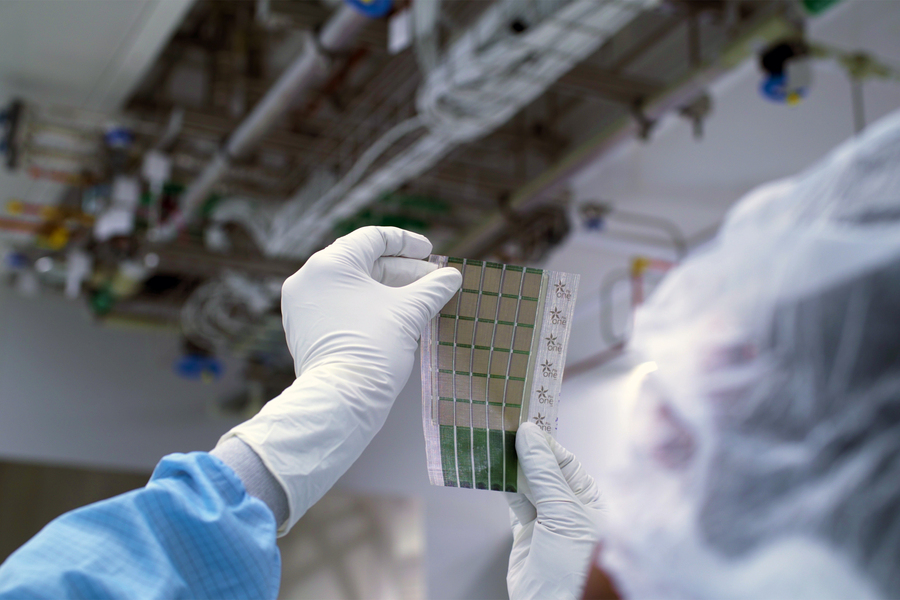
Previous image Next image
MIT engineers have developed ultralight fabric solar cells that can quickly and easily turn any surface into a power source.
These durable, flexible solar cells, which are much thinner than a human hair, are glued to a strong, lightweight fabric, making them easy to install on a fixed surface. They can provide energy on the go as a wearable power fabric or be transported and rapidly deployed in remote locations for assistance in emergencies. They are one-hundredth the weight of conventional solar panels, generate 18 times more power-per-kilogram, and are made from semiconducting inks using printing processes that can be scaled in the future to large-area manufacturing.
Because they are so thin and lightweight, these solar cells can be laminated onto many different surfaces. For instance, they could be integrated onto the sails of a boat to provide power while at sea, adhered onto tents and tarps that are deployed in disaster recovery operations, or applied onto the wings of drones to extend their flying range. This lightweight solar technology can be easily integrated into built environments with minimal installation needs.
“The metrics used to evaluate a new solar cell technology are typically limited to their power conversion efficiency and their cost in dollars-per-watt. Just as important is integrability — the ease with which the new technology can be adapted. The lightweight solar fabrics enable integrability, providing impetus for the current work. We strive to accelerate solar adoption, given the present urgent need to deploy new carbon-free sources of energy,” says Vladimir Bulović, the Fariborz Maseeh Chair in Emerging Technology, leader of the Organic and Nanostructured Electronics Laboratory (ONE Lab), director of MIT.nano, and senior author of a new paper describing the work.
Joining Bulović on the paper are co-lead authors Mayuran Saravanapavanantham, an electrical engineering and computer science graduate student at MIT; and Jeremiah Mwaura, a research scientist in the MIT Research Laboratory of Electronics. The research is published today in Small Methods.

Slimmed down solar
Traditional silicon solar cells are fragile, so they must be encased in glass and packaged in heavy, thick aluminum framing, which limits where and how they can be deployed.
Six years ago, the ONE Lab team produced solar cells using an emerging class of thin-film materials that were so lightweight they could sit on top of a soap bubble . But these ultrathin solar cells were fabricated using complex, vacuum-based processes, which can be expensive and challenging to scale up.
In this work, they set out to develop thin-film solar cells that are entirely printable, using ink-based materials and scalable fabrication techniques.
To produce the solar cells, they use nanomaterials that are in the form of a printable electronic inks. Working in the MIT.nano clean room, they coat the solar cell structure using a slot-die coater, which deposits layers of the electronic materials onto a prepared, releasable substrate that is only 3 microns thick. Using screen printing (a technique similar to how designs are added to silkscreened T-shirts), an electrode is deposited on the structure to complete the solar module.
The researchers can then peel the printed module, which is about 15 microns in thickness, off the plastic substrate, forming an ultralight solar device.
But such thin, freestanding solar modules are challenging to handle and can easily tear, which would make them difficult to deploy. To solve this challenge, the MIT team searched for a lightweight, flexible, and high-strength substrate they could adhere the solar cells to. They identified fabrics as the optimal solution, as they provide mechanical resilience and flexibility with little added weight.
They found an ideal material — a composite fabric that weighs only 13 grams per square meter, commercially known as Dyneema. This fabric is made of fibers that are so strong they were used as ropes to lift the sunken cruise ship Costa Concordia from the bottom of the Mediterranean Sea. By adding a layer of UV-curable glue, which is only a few microns thick, they adhere the solar modules to sheets of this fabric. This forms an ultra-light and mechanically robust solar structure.
“While it might appear simpler to just print the solar cells directly on the fabric, this would limit the selection of possible fabrics or other receiving surfaces to the ones that are chemically and thermally compatible with all the processing steps needed to make the devices. Our approach decouples the solar cell manufacturing from its final integration,” Saravanapavanantham explains.
Outshining conventional solar cells
When they tested the device, the MIT researchers found it could generate 730 watts of power per kilogram when freestanding and about 370 watts-per-kilogram if deployed on the high-strength Dyneema fabric, which is about 18 times more power-per-kilogram than conventional solar cells.
“A typical rooftop solar installation in Massachusetts is about 8,000 watts. To generate that same amount of power, our fabric photovoltaics would only add about 20 kilograms (44 pounds) to the roof of a house,” he says.
They also tested the durability of their devices and found that, even after rolling and unrolling a fabric solar panel more than 500 times, the cells still retained more than 90 percent of their initial power generation capabilities.
While their solar cells are far lighter and much more flexible than traditional cells, they would need to be encased in another material to protect them from the environment. The carbon-based organic material used to make the cells could be modified by interacting with moisture and oxygen in the air, which could deteriorate their performance.
“Encasing these solar cells in heavy glass, as is standard with the traditional silicon solar cells, would minimize the value of the present advancement, so the team is currently developing ultrathin packaging solutions that would only fractionally increase the weight of the present ultralight devices,” says Mwaura.
“We are working to remove as much of the non-solar-active material as possible while still retaining the form factor and performance of these ultralight and flexible solar structures. For example, we know the manufacturing process can be further streamlined by printing the releasable substrates, equivalent to the process we use to fabricate the other layers in our device. This would accelerate the translation of this technology to the market,” he adds.
This research is funded, in part, by Eni S.p.A. through the MIT Energy Initiative, the U.S. National Science Foundation, and the Natural Sciences and Engineering Research Council of Canada.
Share this news article on:
Press mentions, fast company.
MIT researchers have developed paper-thin solar cells that can adhere to nearly any material, reports Elissaveta M. Brandon for Fast Company. “We have a unique opportunity to rethink what solar technology looks like, how it feels, and how we deploy it,” says Prof. Vladimir Bulović.
MIT researchers have developed an ultra-thin solar panel that can adhere to any surface for access to immediate power, reports Jules Suzdaltsev for Mashable . “These ultra-portable panels can make the difference in remote regions where emergencies require more power,” writes Suzdaltsev.
Researchers at MIT have developed a new ultrathin solar cell that can adhere to different surfaces providing power on the go, reports Clara McCourt for Boston.com . “The new technology surpasses convential solar panels in both size and ability, with 18 times more power per kilogram at one-hundredth the weight,” writes McCourt.
Popular Science
Popular Science reporter Andrew Paul writes that MIT researchers have developed a new ultra-thin solar cell that is one-hundredth the weight of conventional panels and could transform almost any surface into a power generator. The new material could potentially generate, “18 times more power-per-kilogram compared to traditional solar technology,” writes Paul. “Not only that, but its production methods show promising potential for scalability and major manufacturing.”
Previous item Next item
Related Links
- Organic and Nanostructured Electronics Laboratory
- Vladimir Bulović
- Research Laboratory of Electronics
- Department of Electrical Engineering and Computer Science
Related Topics
- Electronics
- Nanoscience and nanotechnology
- Renewable energy
- Materials science and engineering
- Electrical Engineering & Computer Science (eecs)
- National Science Foundation (NSF)
Related Articles

Researchers develop a paper-thin loudspeaker

Researchers improve efficiency of next-generation solar cell material

Transparent, flexible solar cells
Solar cells as light as a soap bubble
More mit news.

MIT Corporation elects 10 term members, two life members
Read full story →

Diane Hoskins ’79: How going off-track can lead new SA+P graduates to become integrators of ideas

Chancellor Melissa Nobles’ address to MIT’s undergraduate Class of 2024

Noubar Afeyan PhD ’87 gives new MIT graduates a special assignment

President Sally Kornbluth’s charge to the Class of 2024

Commencement address by Noubar Afeyan PhD ’87
- More news on MIT News homepage →
Massachusetts Institute of Technology 77 Massachusetts Avenue, Cambridge, MA, USA
- Map (opens in new window)
- Events (opens in new window)
- People (opens in new window)
- Careers (opens in new window)
- Accessibility
- Social Media Hub
- MIT on Facebook
- MIT on YouTube
- MIT on Instagram

Russell Millner/Alamy
Defend Our Planet and Most Vulnerable Species
Your donation today will be triple-matched to power NRDC’s next great chapter in protecting our ecosystems and saving imperiled wildlife.
Solar Power 101
How renewable energy from the sun can mean a brighter future for people and the planet.

Solar farms, like this one located in the Carrizo Plain in California, use the sun's rays to generate clean, renewable energy.
Markus Altmann/Getty Images

- Share this page block
Did you know that people have harnessed the power of the sun at least as far back as 700 BCE, when glass lenses were used to magnify sunlight and create fire? It’s easy to imagine how the sun’s energy—the way it provides warmth and light—has always inspired the human mind.
Today, we know that the sun’s rays can actually provide endless clean electricity, and great progress has been made to make that renewable energy as affordable as possible. In fact, solar power is one of the nation’s fastest-growing energy sectors, with more than half of all new generating capacity coming from solar in 2023.
But how can sunshine recharge your smartphone, refuel your electric car, warm your bath, and keep your appliances humming? Read on to learn more.
What is solar energy?
Types of solar power, advantages of solar energy, challenges with solar energy, the future of solar energy.
Solar energy refers to the electrical or thermal energy that is created from solar radiation—the power of the sun. Solar energy is also called solar power, or even just solar , for short.
The sun emits an enormous amount of radiation onto Earth: around 44 quadrillion watts of power a year. However, the amount of solar energy that can be generated depends not only on the technology and equipment used but factors like geography, season, time of day, and even the shade of local trees and buildings.
Because the energy source—the sun—is not depleted over time (or at least in a timeline that concerns us mortal humans), it is considered renewable energy.
One important note: Throughout this guide, we’ll reference solar power at two scales, which have different qualities and costs:
- Residential, or rooftop, solar: small systems installed on top of or near homes or businesses. These energy sources are relatively easy to install, often taking advantage of existing infrastructure like rooftops. Because of the way these smaller, scattered systems plug into the grid, they’re considered “distributed” energy resources.
- Utility-scale, or commercial, solar: larger systems that operate like a typical power plant, providing energy to entire neighborhoods. These systems require more space and infrastructure than residential solar and are typically owned by utilities (aka power companies), which sell the energy to their customers on the local grid. Terms like solar farms and solar plants refer to these utility-scale solar power plants. While distributed solar may be cheaper to set up because they are smaller, utility-scale solar systems cost less per kilowatt-hour (kWh) because of economies of scale.
There are two main types of solar energy: photovoltaic power and thermal power. Both utilize sunlight as a fuel but they harness it in different ways.
Photovoltaic power
Photovoltaic (PV) energy, which converts sunlight directly into electricity, is what most people think of when we talk about solar power. PV panels are the large black or blue modules you see in places like residential rooftops and parking lots, or clustered together in utility-scale solar farms. Each PV panel is made up of individual PV cells, and several connected panels form a solar array.

Solar installers set up panels at the Van Nuys Airport in Los Angeles, taking advantage of the vast rooftop space.
Richard Vogel/AP Photo
But how does sunlight become electricity, exactly? PV cells contain semiconductor material: silicon, most commonly. When sunlight—which is made up of tiny bits of energy called photons—hits the PV cell, the material absorbs the photons, which dislodge electrons. This movement of electrons creates an electrical current.
Metal connectors on the side of each PV cell then transfer the electricity to wires and to an inverter, which feeds this current into our electrical grid.
It takes about 20 solar panels to satisfy the 11,000 kWh of power consumed by a typical U.S. household every year.
Thermal power
There’s nothing quite like the feeling of warm sunlight on a cool, crisp day. Amazingly, we can harness this heat, or thermal energy, for many things. Thermal energy can be used to warm the water for your shower or, more passively, maintain a comfortable temperature inside your home. We can even use it to generate electricity at a massive scale.
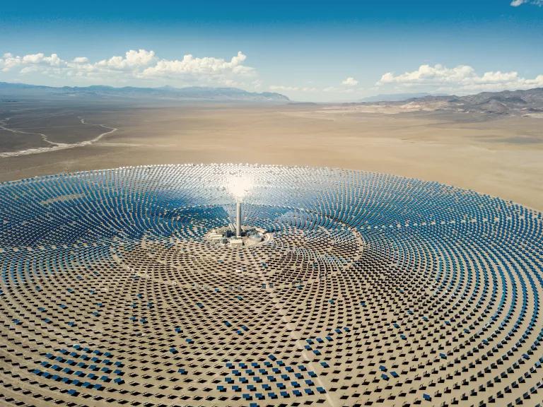
When it opened in 2014, the Ivanpah Solar Electric Generating System in California was the world’s largest concentrated solar-thermal plant.
Mlenny/Getty Images
Concentrated solar-thermal power
Just as humans first focused sunlight with glass lenses more than 2,700 years ago, concentrated solar-thermal power (CSP) creates electricity using the same basic mechanism. CSP utilizes mirrors to point sunlight into a receiver to heat up a fluid and generate steam. That steam spins the turbines that then create electricity.
CPS systems are utility-scale solar plants that are typically built on large swaths of land and can power tens of thousands of homes and businesses.
One of the advantages of a CPS system is that the fluid can retain the heat for a long time, which is especially handy on cloudy days when CPS systems aren’t able to harness as much sunlight. However, the technology is still in limited use and the industry is not expected to grow as much as utility-scale PV solar.
Gas- and coal-powered plants also use steam to spin turbines but with CSP, there’s no nasty pollution or waste—or climate-warming emissions—like there are from burning fossil fuels.
Passive solar design
Most of us have seen at least one example of passive solar heating: a greenhouse, which is designed to take maximum advantage of sunlight.
A passive solar system isn’t so much about equipment as it is about strategy. This method of controlling indoor temperatures doesn’t even require electricity—just the right building materials and conditions to take advantage of the sun’s warmth.
Whether it’s primarily for heating or cooling, there are a few key requirements for a passive solar system in a building:
- Aperture: large windows that face within 30 degrees of true south, with no shade between 9 a.m. and 3 p.m. (In North America, this is where the sun sits the highest during the day.)
- Thermal mass: materials like concrete, brick, or stone that can hold onto heat
- Distribution: Thermal energy is distributed around the building via: conduction, like when you touch the thermal mass; convection, moving thermal energy through the air, as through vents and fans; or radiation, moving through electromagnetic waves.
- Controls: things like thermostats, awnings, or blinds that can help prevent overheating or under-heating the building throughout all kinds of weather
Solar water heaters
The sun’s thermal power can also be used to heat tap water in a home or business. Similar to the PV systems, solar water heaters utilize collector panels to absorb solar radiation. Water will heat up as it’s circulated through the panels and sent to a storage tank. These panels are typically installed on rooftops to capture the most direct sunlight, and some systems include pumps and valves to move the water through the system.
For a typical U.S. home, heating water accounts for a good chunk of its total energy use: about 20 percent. The cost of a solar water heater varies, based on factors such as the size of the storage tank, how many collector panels are needed, and installation fees. And while it can be pricier up-front compared with a conventional water heater, a solar water heater can cut your water heating bills by 50 to 80 percent. That’s because sunlight is free!
(If you’re not in such a sunny location, heat pump water heaters are another efficient and eco-friendly option.)
Solar power—along with wind energy and other renewable technologies—is lighting the path toward a future without fossil fuels.
Clean and renewable energy source
Unlike power plants that rely on fossil fuels, solar energy does not produce greenhouse gases or air and water pollution. That’s because nothing is burned. And the more we develop and install solar power, the less we will have to depend on dirty sources of electricity.
Building up more solar energy at residential and utility scales also makes our electrical grid more reliable , especially under the stress of extreme weather—like the heat waves that can send our energy consumption soaring to the point of blackouts. Solar energy is a major climate solution , helping us not only adapt to climate change but to mitigate it.
Job creation and economic growth
Clean energy jobs are on the rise across the United States, especially as private and public investments are plugged in. Solar leads as a top employer within renewable energy, with more than 346,000 people employed in the U.S. solar sector in 2022. And these jobs aren’t limited to installing solar panels on rooftops but spread out across construction, manufacturing, software, and science.

The booming clean energy industry is making way for new jobs, including solar installation and manufacturing.
Sandy Huffaker/Bloomberg via Getty Images
Megan Jelinger/Reuters
Cost savings
With the increased efficiency of solar technology comes decreased costs. And these aren’t small savings, either. The National Renewable Energy Laboratory found an 85 percent cost reduction in PV modules between 2010 and 2021, whether residential or utility scale. In fact, electricity from utility-scale solar is now almost always less expensive than electricity from gas or coal.
And if we compare clean solar with the polluting fossil fuel technologies that have dominated the energy landscape for the past century, the savings for public health care are astronomical.
Although solar technology isn’t new, the sector is still evolving to become more efficient, affordable, and accessible. Here are some of the challenges the sector is working to address.
Weather and location dependency
Naturally, solar power depends on how much sunlight can be reached. For instance, PV panels do not generate as much energy on a cloudy day, or if they’re blocked by a tree during daylight hours—and they stop generating electricity altogether at night.
This is where battery storage comes in. Whether at the residential or utility scale, batteries can store the energy generated during sunny periods so that it can be accessed when the sun isn’t shining or energy use is extra high.

Energy storage, like at Orsted’s Eleven Mile Solar lithium-ion battery storage facility in Coolidge, Arizona, helps maintain a steady supply of electricity when the sun isn’t shining.
Ross D. Franklin/AP Photo
The future looks even brighter as the United States modernizes its grid infrastructure , including increasing capacity, plugging in more distributed energy sources (including small solar systems), and building new transmission lines. And solar energy isn’t the only renewable energy source on the market: Wind energy is also rapidly expanding across the country.
High initial cost
While the cost of installing a residential solar system has dropped, a typical home system requires an average initial investment of about $25,000 . The good news is that if the solar system can cover all of your electricity needs, you can save that amount or even thousands more over the 35-year lifetime of the system. And clean energy tax credits are making it that much easier to recoup your initial investment.
Community solar projects, through which customers join together to collectively purchase and use locally produced solar energy, are also a great option for businesses and homes (benefiting owners and renters alike). Typically, participants can pay a monthly subscription to access solar energy or purchase a portion of the panels. Both subscribers and owners will also receive credit from the utility to cover any excess energy that their share of solar panels produce to reduce their electricity bills. Community solar is also a good solution if your rooftop isn’t suitable for solar panels, like if your property is shaded or your roof is aging.
Solar owners can potentially pay little or nothing for electricity if they generate more energy than they use. Depending on the specific city and state policies, some utility companies (as in California ) offer net metering programs that exchange access to residents’ and businesses’ excess electricity for credits toward their bills.
Environmental concerns
Since utility-scale solar farms and plants do not generate any carbon emissions while operating, solar energy is an asset in the fight against climate change. In fact, moving from fossil fuels to clean energy means reduced air and water pollution, as well as water consumption.
However, the siting, production, and end-of-life phases of solar equipment, like in any other power sector, involve resources and waste that can potentially have negative impacts.
A sorting machine breaks down solar panels at North America’s first utility-scale solar panel recycling plant, We Recycle Solar, in Yuma, Arizona.
Gregory Bull/AP Photo
Thankfully, end-of-life impacts from solar are low, as the materials in modern panels pose no threat of leaching. Nevertheless, recycling panels is better but currently very limited. NRDC, the electric utility industry, and the solar industry have jointly called for more investment and public support for building the infrastructure needed to support more recycling.
The growing industry is taking steps to address other issues head-on. For example, utility-size solar plants require a lot of space. One way to address this is with agrivoltaics, which combines solar and farming on the same land. The U.S. Department of Energy (DOE) has designated millions of dollars to researching how this promising field can grow. The land usage challenge can also be addressed by siting solar farms on degraded land, such as brownfields or retired landfills .

Sheep graze and rest among solar panels at Cornell University in Ithaca, New York.
Heather Ainsworth/AP Photo
Part of the responsibilities of the DOE’s Solar Energy Technologies Office is researching best practices for developing solar energy with minimal impacts on the environment. This includes how PV cells and other solar components might be built to last longer and then recycled at the end of their lifespan .
NRDC and other organizations are advocating for a circular economy approach, in which we invest the resources and build out infrastructure so that solar panel components are reused as much as possible, or otherwise safely recycled.
Trade and labor concerns
As we push for a faster transition to renewable energy, it’s important that we avoid the harms that have become the trademarks of the fossil fuel industry. That means fostering an environment where workers are treated as valued stakeholders—investing in the skills and well-being of workers so they can provide positive contributions to local economies and workforce diversity.
Investing in domestic manufacturing is another way in which we can address concerns around labor exploitation in the global solar industry. The 2022 Inflation Reduction Act, which includes the Advanced Manufacturing Production tax credit, does just that by spurring the creation of stable, family-supporting jobs as well as helping the U.S. solar industry compete on the international stage. Moreover, partnership with labor unions can help to reduce burdens on developers, contractors, and customers to meet the requirements of the Inflation Reduction Act and other regulatory hurdles, so we can get solar to market much more efficiently.
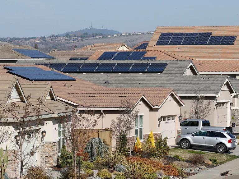
With greater incentives and access, more residents can benefit from rooftop solar, like these homes in Folsom, California.
Rich Pedroncelli/AP Photo
As mentioned above, the Inflation Reduction Act has helped to energize the clean power industry, with $369 billion in investments to help fight climate change. That includes billions to spur solar development, like the clean energy Investment Tax Credit, which provides a 30 percent credit for qualifying solar investments, as well as the extended Residential Clean Energy Credit, which can cover 30 percent of costs for solar installation, among others.
While solar power accounts for just 4 percent of electricity generated in the United States right now, it’s an integral part of a broader, booming renewable energy market.
Unfortunately, fossil fuels are still the primary energy source in the world, by far, and we’ve got a long way to go in achieving net zero emissions by 2050 , as scientists are telling us we must do to avoid the worst impacts of climate change.
The good news is, according to NRDC’s modeling , the recent tax credits could boost generation from utility-scale wind and solar to account for around one-third of the country’s electricity portfolio by 2030—and up to 46 percent by 2035. And unprecedented investments, like Solar for All , are expanding access to residential solar and creating solar programs where none previously existed. So don’t count us down-and-out. A future where it’s lights out for fossil fuels remains in reach.
This NRDC.org story is available for online republication by news media outlets or nonprofits under these conditions: The writer(s) must be credited with a byline; you must note prominently that the story was originally published by NRDC.org and link to the original; the story cannot be edited (beyond simple things such as grammar); you can’t resell the story in any form or grant republishing rights to other outlets; you can’t republish our material wholesale or automatically—you need to select stories individually; you can’t republish the photos or graphics on our site without specific permission; you should drop us a note to let us know when you’ve used one of our stories.
We need climate action to be a top priority in Washington.
Tell President Biden and Congress to slash climate pollution and reduce our dependence on fossil fuels.

Urge President Biden and Congress to make equitable climate action a top priority in 2024
Related stories.

Can Hydrogen Help Combat the Climate Crisis?

Wind Energy
What’s the Most Energy-Efficient Water Heater?
When you sign up, you’ll become a member of NRDC’s Activist Network. We will keep you informed with the latest alerts and progress reports.
Experimental investigation of a sun tracking concentrated solar still with economic analysis
- Original Article
- Open access
- Published: 20 May 2024
- Volume 14 , article number 136 , ( 2024 )
Cite this article
You have full access to this open access article

- Mohammad M. Daif 1 ,
- Mohamed Emam 1 , 2 ,
- M. A. Abdelrahman 1 ,
- Ahmed A. A. Attia 1 &
- Aly M. A. Soliman 1 , 3
316 Accesses
Explore all metrics
The current paper evaluated experimentally an innovative sun tracking concentrated solar still under Egyptian climatic conditions during the summer of 2022. The proposed system consists of a 120-cm-diameter parabolic reflector mirror that tracks the sun using a dual axis tracking system, a cylindrical solar still with a volume of 3.7 L positioned in its focal point, and a concentration ratio of 12.5. The performance of the concentrated solar still was investigated in the context of two critical parameters. First, three feed water salinity (17, 27, 37) ppt samples were evaluated, followed by four percentages of saline water filling ratio (26.5, 39.8, 53.1, 66.3)%. Increasing the salinity of the feed water had no effect on solar still productivity, but increasing the saline water filling ratio did. The daily cumulative productivity of the system was 6 kg/m 2 with an optimal filling ratio of 53.1%, a daily efficiency of 42.88%, and an average cost of freshwater production of 0.0489 $/L. The proposed system also had the highest instantaneous efficiency of 61.77% and the highest distilled water productivity rate of 0.941 kg/h m 2 .
Review of cooling techniques used to enhance the efficiency of photovoltaic power systems
Increasing the productivity and the thermal efficiency of conventional solar stills using a new rotating discs mechanism
Optimum location and influence of tilt angle on performance of solar PV panels
Avoid common mistakes on your manuscript.
Introduction
Freshwater is an important natural resource for the ecosystem's existence and continuity, yet it is in short supply. Even though water covers two-thirds of the planet and is available as sea water and ice glaciers, 97% of it is saline water and the remaining is freshwater; however, only 1% of the freshwater is easily accessible (Omara and Eltawil 2013 ). One of the significant challenges in rural regions is the lack of water for drinking, sanitation, agriculture, and other purposes (Bahrami et al. 2019 ). Desalination is the process of removing minerals, salts, and pollutants from water. The desalination process requires a significant amount of energy; however, using fossil fuel as an energy source is no longer the ideal option because of the environmental impact, as well as the limitations and excessive costs of fossil fuel (Qtaishat and Banat 2013 ). Renewable energy replenishes faster than depletion and is abundant, making it an alternative energy source for use in desalination and may be the sole alternative in rural regions (Renewable Energy|Department of Energy 2023 ). Solar, wind, biomass, and geothermal energy have been used in the desalination process. Solar energy is one of these promising and extensively utilized renewable technologies. The solar collector is a simple and low-cost technology used to concentrate energy in solar desalination processes.
Egypt is in the Earth's Sun Belt; thus, it receives a lot of sunlight, averaging 9–11 h every day. Egypt receives daily direct normal irradiance (DNI) ranging from 5.6 to 7.6 kWh/m 2 (Global Solar Atlas 2023 ), according to the solar atlas. In addition to the abundance of saline water in Egypt from the Mediterranean and the Red Seas, which makes water desalination using solar energy is the most promising technology that warrants further exploration. There are two types of solar desalination processes: direct and indirect. Direct systems in which solar energy is converted into heat and used to evaporate the saline water in the same device such as solar still and humidification Dehumidification systems, while indirect systems are split into two subsystems: a conventional desalination unit and a solar collector (Bait 2020 ; Shatat and Riffat 2014 ; Sakthivadivel et al. 2020 ).
Solar concentrator collector's technologies include solar power tower, parabolic trough collector, solar parabolic dish, and Fresnel reflector (Luo et al. 2018 ; Fredriksson et al. 2021 ; Coventry and Andraka 2017 ; Perini et al. 2017 ). The parabolic dish has a single focal point and uses mirrors or other reflecting foils as reflectors. It is important to be equipped with dual axis tracking to change the azimuth and elevation angles and point directly toward the sun to achieve the greatest DNI on the solar dish concentrator (SDC) (Aliman et al. 2007 ). The parabolic dish concentrator outperforms other concentrators due to its ability to achieve elevated temperature ranges (Jamar et al. 2016 ; Chaouchi et al. 2007 ), and high concentration ratios (Jamar et al. 2016 ). It also has low thermal losses, which results in high thermal efficiency (Jamar et al. 2016 ; Chaouchi et al. 2007 ), and high optical efficiency (Tian and Zhao 2013 ). It can also be utilized in hybrid systems by combining it with other devices (Al-Amayreh et al. 2020 ).
The performance of the solar still has been investigated extensively through extensive scientific research, distinctive designs were proposed, and various parameters have been studied. These enhancements occurred on the conventional solar still since it is easy to fabricate at low cost, but their main drawback is their low productivity. Manokar et al. ( 2020 ) studied experimentally the influence of water depth on pyramid solar still. The cumulative productivity was reduced by 8.6, 27.42, and 44.09% for water depths of 2, 3, and 3.5 cm, respectively, compared to water depth of 1 cm. Rahmani et al. ( 2020 ) experimentally considered the effect of the external condenser on the performance of the solar still. The results showed that adding external condenser does not always have a positive effect, and the performance is related to the weather condition. In moderate weather it improved solar still productivity by 29%, while in excessively hot or cold weather it decreased the productivity by 16.5%. Panchal et al. ( 2021 ) demonstrated experimentally the effect of black paint mixed with graphite powder on the absorber plate on the productivity. The graphite powder increased productivity when compared to CSS by 10.5% and 17%, for a weight fraction concentration of 20% and 40%, respectively. Al-Harahsheh et al. ( 2022 ) investigated experimentally connecting solar collector and using PCM on the performance of solar still. According to the results, adding a solar collector increased productivity by 340% then adding the PCM to that system increased its productivity by another 50%.
Furthermore, to increase the productivity of the solar still it was integrated with solar concentrators. The parabolic trough, for example, is utilized to concentrate the radiation incident on its aperture area into the focal line where the receiver is mounted to absorb that concentrated heat. Elashmawy ( 2017 , 2020 , 2019 ) and Elashmawy and Alshammari ( 2020 ) integrated parabolic trough with solar still has improved the daily yield by 676% while reducing the CPL by 45.5%, while the spraying and concentric tubes cooling reduced the productivity by 10% and 43.8%, and the efficiency by 7.79% and 42.63%, respectively. Furthermore, the black gravel as a sensible energy storage material enhanced productivity and efficiency by 14.18% and 13.89%; finally, adding a parabolic trough to tubular solar still with desiccant enhanced productivity and efficiency by 292.4 and 82.3%, respectively, and reduced the CPL by 25%.
Moreover, for achieving higher temperature ranges and concentrator ratios the dish is utilized. Chaouchi et al. ( 2007 ) explored theoretically and experimentally combining a solar still with a 1.8 m parabolic dish concentrator attaining a concentration ratio of 195. The predicted productivity of the system was 10.4 L with an average relative error of 42% compared to the experimental. Prado et al. ( 2016 ) studied theoretically the impact of salinity on daily productivity of dish concentrator solar tracking with evaporator, and it was validated experimentally. According to results, raising the salt concentration from 0 to 4% lowered the distilled yield from 4.95 to 4.11 kg/m 2 .day. Other recent studies incorporating solar still with solar concentrator regarding configuration, location, methodology, absorber and concentrator areas, concentration ratio, salinity, average solar intensity, average productivity, and daily efficiency are listed in Table 1 .
Previous research highlighted an urgent need for greater investment and further investigation into solar water desalination technologies. Solar still remains one of the simplest, easiest, and cheapest solar desalination devices, which is distinguished by the availability of its components locally. It is an essential choice for delivering drinkable water to humans while camping, exploration excursions, or isolated residences in remote areas or contaminated water areas. Because conventional solar stills have a poor productivity per square meter due to the considerable heat loss via the large area of the transparent surface, whether glass or plastic, numerous research has been conducted to enhance their efficiency and productivity. Since the transparent surface is the main cause of this drop in productivity, researchers began to work toward eradicating it by developing concentrated solar stills that maximize freshwater productivity by focusing radiation via parabolic concentrator's mirrors. Concentrated solar stills attempt to replace expensive metal absorber surfaces with less expensive plastic or glass concentrator surfaces. Despite being a promising technology with high applicability, there have been few studies on concentrated solar stills.
As a result, the current study intends to investigate experimentally the performance of a new sun tracking concentrated solar still in hot weather in Egypt at various feed water salinities and saline water filling ratios. The suggested system consists of 120-cm-diameter parabolic reflectors that are controlled by a dual axis solar tracking system. A 20-cm-diameter cylindrical solar still made of stainless steel and a 34-cm-diameter copper absorber are positioned at the focal point of the parabolic reflectors with a concentration ratio of 12.5. The solar still's innovative design separated the evaporator and condenser, allowing sun tracking without mixing the produced vapor with saline water or condensate. The solar irradiation incident on the SDC's aperture area is reflected to the solar still's absorber plate, it has an automatic sun tracking system to direct radiation normally to the receiver positioned in the focal point. The saline water in the solar still evaporates, generating vapor that condenses in the stainless-steel hose condenser. The proposed concentrator solar still's performance was evaluated under different atmospheric conditions using various operating parameters such as feed water salinity, where three different feed water salinities (17 ppt, 27 ppt, and 37 ppt) were assessed, which are suitable for either sea water or brackish water. Furthermore, several saline water filling ratios of 26.5%, 39.8%, 53.1%, and 66.3% were examined in order to determine the optimal ratio that yields maximum freshwater productivity. Aside from the system's uniqueness, the system is self-contained, and it may be powered by a solar cell, which is beneficial in off-grid rural areas. The system also has a small footprint, which may be beneficial in terms of preserving huge tracts of land; this feature can be capitalized on by mounting the new system on wind turbine towers and providing freshwater to employees and neighboring populations.
Experimental setup
An innovative concentrated solar still was designed and fabricated; Fig. 1 provides the layout of the setup, while Fig. 2 a introduces the pictorial view. All experiments were conducted on the roof of Shoubra engineering college (30.07° N, 31.24° E) under the climatic conditions of Cairo city in Egypt during the months of June, July, and August 2022. A 120-cm-diameter solar dish concentrator (aperture area of 1.13 m 2 ) with 4 cm × 4 cm mirror pieces glued to its surface was utilized to reflect solar irradiation on its focal point, where the solar still is mounted.
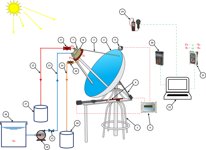
A layout of the experimental setup
a Sun tracking concentrated solar still experimental setup, cylindrical solar still, b detailed schematic diagram, c actual photograph
As shown in Fig. 2 b, a cylindrical stainless steel solar still with a 5 mm thickness, 20 cm diameter, and 12 cm height is bolted to a 3 mm thick, and 34-cm-diameter copper absorber plate with a rubber sealing in between to prevent water and vapor leakage. The solar still has four ports, as shown in Fig. 2 c. The first is the make-up port, which is located on the solar still's top surface and is used to add water or flush the solar still of the brine. The vapor output port, which is also located at the top of the solar still where steam escapes and condenses. The drain port at the bottom of the absorber plate drains the solar still from the brine water. Finally, the thermocouple port is located on the solar still's lateral surface and is used for thermocouples' insertion inside the solar still to monitor temperatures. To prevent heat losses from the solar still's side wall and top, 1 inch glass wool insulation is used, and the copper absorber at the bottom is painted with black selective coating to enhance solar radiation absorptivity.
Table 2 contains detailed descriptions of the experimental test rig main components. A dual axis tracking system was utilized to position the SDC directly normal to the incident solar radiation, ensuring that the radiation is consistently concentrated on the SDC's focal point. The tracking system is powered by two actuators, one of which spins the main axis of the system base from north to south with 225° degrees of freedom to alter the azimuth angle, whereas the other adjusts the elevation angle. These actuators are pre-configured with a WST03-2 solar tracking controller and powered by a 24 Volt AC/DC converter. To feed the solar still, a 0.3 HP water pump circulates saline water from the storage tank into the solar still make-up port.
Temperatures of the absorber plate inner surface, saline water in the evaporator, and vapor generated were monitored and measured using T-Type thermocouples, the probes were inserted into the solar still, thermocouples were connected to a multi-channel data recorder (MCR-4TC). The outside temperature of the absorber plate was measured using a Fluke Ti32 thermal imager, and the temperatures of saline water in the storage tank and distilled water in the yield tank were measured using a mercury thermometer. The ambient temperature and wind speed were measured using a WT8907 digital anemometer. While the direct normal irradiance incident normal to the parabolic dish was measured using a TES-1333R data recording solar power meter.
Experimental procedures
The practical experiments were conducted from June to August 2022, from 8:00 to 18:00 where they were performed on sunny days with an average direct solar irradiation of 824.2–923.2 W/m 2 . In the current study, the performance of the concentrated solar still was evaluated under three different feed water salinities prepared by dissolving Sodium Chloride in freshwater to simulate Mediterranean water (37 ppt) and Brackish water (27 ppt and 17 ppt). Furthermore, each of the prepared saline water samples is employed in a variety of saline water filling ratios \(\varnothing \) , which are the ratios of the saline water inside the solar still to the volume of the solar still itself. Whereas the solar still is filled with 1, 1.5, 2, and 2.5 kg of saline water, corresponding to filling ratios of 26.5, 39.8, 53.1, and 66.3%, respectively. Every experiment began with cleaning the SDC's reflecting mirrors with a dry microfiber cloth, followed by spraying glass cleaner and wiping it. Then flush the solar still by circulating freshwater multiple times to make sure any residual brine from the previous experiment is removed and pump the saline water sample examined to the solar still. Run the measuring devices and double-check that everything is ready to begin the experiment. The experiment begins at 8:00, and all data are collected at 15-min intervals throughout the day. Whenever distilled water equal to 25% of the saline water charged in the still is obtained, the same amount of saline water is added as make-up. The tracking system is turned off and the experiment is finished at 18:00 during the sunset, the wastewater is discharged through the drain port, and the solar still is backwashed. The same procedures were repeated for the rest of experiments. The temperatures of ambient air, absorber internal and external surfaces, saline water inside the evaporator, vapor was measured, along with wind speed, direct normal irradiance, mass of distilled water yield were all monitored and recorded every 15 min.
The uncertainty analysis is crucial for experimental data obtained by the measuring devices to evaluate the accuracy of measurements. Table 3 shows the uncertainties associated with various experimental measuring devices such as solar power meter, thermocouples, and anemometer; these values are provided by the device datasheet. The Holman's method (Holman) is used to estimate the total uncertainty in the experimental data. The total uncertainty in the daily distilled productivity and the daily system efficiency of the experimental data results is calculated by Eq. ( 1 ):
where ω x and ω y are the independent variables uncertainties.
According to the uncertainty Eq. ( 1 ), the maximum total uncertainty in calculating the daily distilled productivity and the daily system efficiency is approximately 0.37% and 1.12%, respectively.
Data reduction
The following are the essential mathematical equations for comprehending the concentrated solar still and its performance based on the data acquired and recorded throughout the experiments:
The concentration ratio, which is the ratio of the dish aperture area ( A dish ) to the absorber area ( A abs ), is the most essential aspect in the design and construction of solar concentrators, as stated by Eq. ( 2 ):
The incident heat on SDC is calculated using Eq. ( 3 ):
where A dish is the aperture area of SDC (m 2 ) and DNI is the direct normal irradiance incident on the SDC surface (W/m 2 ).
The heat concentrated on the solar still's absorber plate is computed as a function of the heat incident and is provided by Eq. ( 4 ):
The concentrator efficiency η conc , defined as the ratio of heat received by the absorber to heat incident on SDC, is influenced by the optical characteristics of the materials utilized as well as the shape; it is computed by Eq. ( 5 ):
where ρ represents the reflectivity of SDC mirrors, Γ the intercept factor, and f s the shading factor generated by solar still on SDC mirrors.
Heat is lost from the absorber plate to the environment through two mechanisms: radiation and convection. Radiation heat loss is classified into two types: reflected and emitted. To begin, reflected radiation heat loss is computed using Eq. ( 6 ):
where ρ abs denotes absorber reflectivity.
The emitted radiation heat loss is given by Eq. ( 7 ):
where ε abs denotes the absorber emissivity and σ is Stefan–Boltzmann constant, which is \(5.67\times {10}^{-8}\) W/m 2 K 4 . The absorber and ambient temperatures (K) are represented by T abs and T amb are, respectively.
The external convection heat loss on an angled heated flat plate is computed by Eq. ( 8 ):
where h is the convection heat transfer coefficient (W/m 2 K) calculated using Eq. ( 11 ) and is a function of the Nusselt Number determined by Eq. ( 9 ):
where Re is the Reynolds Number determined from Eq. ( 10 ) and θ is the angle formed between the absorber plate and the vertical.
where V wind is the wind velocity (m/s), L c is the characteristic length (m), and ν is the air kinematic viscosity (m 2 /s).
where Nu represents the Nusselt Number and K air denotes the thermal conductivity of air (W/m K).
The useful heat energy entering the absorber equals the concentrated heat minus the heat losses, as determined by Eq. ( 12 ):
The system efficiency is computed from Eq. ( 13 ):
where m distilled denotes the mass of distilled yield (kg), h fg represents the latent heat of vaporization of water (J/kg), and ∆t denotes the time (s).
Results and discussion
The effects of saline water salinity and saline water filling ratio on concentrated solar still performance under various weather conditions have been demonstrated in this section.
The weather data for a typical test day (Wednesday, July 28, 2022) are illustrated in Fig. 3 . The ambient air temperature was minimum 33.2 °C at 8:15 and continuously rises throughout the experiment until it reaches its peak around 42 °C in the afternoon from 14:00 to 14:15. While the wind velocity varies substantially throughout the experiment, it reaches a maximum of 3.43 m/s at 15:15 and a minimum of 0.18 m/s at 8:30. The maximum direct normal irradiance (DNI) was 992.4 W/m 2 at 9:00, and minimum of 443.6 W/m 2 at sunset (18:00) while it has an average of 876.9 W/m 2 throughout the day, with a slight decline due to clouds between 10:00 and 10:15.
Ambient temperature and wind speed during a typical test (July 28, 2022)
Hourly variations of outside and inside temperatures of the absorber plate, temperature of saline water inside the evaporator, and the produced vapor temperature on Wednesday, July 28, 2022, with a filling ratio of 53.1% and feed water salinity of 17 ppt are presented in Fig. 4 . At 8:00, the temperatures of the absorber plate outside and inside, saline water in the evaporator, and the vapor were 46.2, 43.9, 40.3, and 38.4 °C, respectively. The figure clearly shows that all the temperatures increase with time during the buildup period until they reach the boiling point at 9:00, when the outside and inside temperatures of the absorber plate were 110.4 and 107.9 °C, respectively, and the temperature of the saline water in the evaporator, and the vapor produced were 102.9, and 100.3 °C, respectively, the slightly higher boiling temperature of water is due to the salinity of water being tested as recent studies have proved.
Hourly temperature variation in a solar still at filling ratio 53.1%, and feed water salinity of 17 PPT (July 28, 2022)
It can be seen that the system's temperatures are affected by the DNI, the system has fast response since temperatures dropped between 10:00 and 10:15, it depends on DNI only and not ambient temperature since the system is totally insulated except the small area of absorber. At 17:30, the outside and inside temperatures of the absorber plate begin to fall slightly below the temperatures of the saline water and vapor in the solar still because of the decrease of DNI, while the system's productivity is dependent on the stored heat in the solar still during this period.
Following that, solar still hourly distilled water productivity fluctuation at filling ratio 53.1% and feed water salinity of 17 PPT on Wednesday, July 28, 2022, are shown in Fig. 5 . Between 8:00 and 18:00, roughly 6 kg/m 2 of distilled water was produced, where the cumulative productivity gradually increases over time. The produced distilled water rate was zero during the first hour due to energy buildup inside the solar still and then reached a maximum of 0.941 kg/h m 2 at 12:00, when the ambient temperature was high and the wind speed was low, resulting in small thermal losses, as shown in Fig. 5 . The effect of DNI drop on the productivity was at 10:30 with a slight lag between the productivity and the DNI.
Solar still hourly distilled water productivity fluctuation at filling ratio 53.1%, and feed water salinity of 17 PPT (July 28, 2022)
The incident heat ( Q solar ), concentrated heat ( Q conc ), and useful heat ( Q useful ) are calculated from Eqs. ( 3 ), ( 4 ), and ( 12 ), respectively. The incident heat is dependent on DNI and follows the same pattern as shown in Fig. 6 . While the difference between the incident heat and concentrated heat curves is due to collector efficiency, which is impacted by optical properties and geometry; both curves exhibit the same variation. Finally, the variance between the concentrated heat and useful heat curves is attributable to heat losses by radiation (reflection and emission) and convection, which are calculated using Eqs. ( 6 ), ( 7 ), and ( 8 ), respectively. These losses fluctuate continuously due to several uncontrollable factors; as a result, the useful heat varies substantially as seen in Fig. 6 .
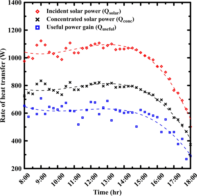
Hourly fluctuation in heat transfer rates in a solar still at filling ratio 53.1%, and feed water salinity of 17 PPT (July 28, 2022)
Effect of filling ratio on solar still performance
The solar still filling ratio has a significant impact on daily distilled productivity, system efficiency, and performance. As shown in Figs. 9, 10 and 11, the daily distilled productivity and the system efficiency increased by increasing the filling ratio of the still, from 26.5 to 53.1%, whereas from 53.1 to 66.3% decreased the performance of the solar still.
At the beginning the performance increases due two parameters: first when the filling ratio increased the make-up cycle (that previously described in experimental procedures section) frequency is decreased which absorb energy for added water to reach the evaporation temperature, second the increased filling ratio has a surface area of contact with absorber plate greater than lower filling ratio that make better heat transfer coefficient for the system, as illustrated in Fig. 7 .

Schematic diagram of solar still at average elevation angle of 50° with different filling ratios a 26.5%, b 39.8%, c 53.1%, d 66.3%
The contact area between water and absorber plate changes during the day due to sun tracking and frequent variations in elevation angle, as seen in Fig. 8 . The area of the free water surface, which is the evaporation surface, is constant at a different filling ratio at the same angle of elevation as shown in Fig. 7 , while bubbles form on the heating surface of the absorber plate and then rise to the evaporation surface. The longer the distance the bubbles travel, the higher resistance to the rate of evaporation. This effect over-controls when the filling ratio is 66.3%, and the reason behind the drop in the performance of the solar still.
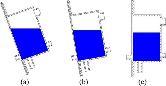
Schematic diagram of solar still at filling ratio 66.3% at various elevation angles a 20°, b 10°, c 0°
The rate of distilled water for various filling ratios 26.5%, 39.8%, 53.1% and 66.3% for different water salinity 17, 27 and 37 PPT is shown in Fig. 9 . The distilled water rate goes up by increasing the filling ratio up to 53.1% before decreasing at 66.3% in all three salinities. The curves can be divided into three periods, first period from 9:00 to 11:00 where the curves are steepest as it is the period of energy buildup, second period from 11:30 to 13:30 where the curves are almost flat where the coming heat energy is utilized for evaporation, third period from 14:00 to 18:00 where the curves are less steep as the DNI gradually decreases while the latent heat is reserved within the solar still. For feed water salinity of 17 ppt, the distilled rates reach their maximum values at 12:00 of 0.829, 0.854, 0.941, and 0.898 kg/hr.m 2 for filling ratios of still of 26.5, 39.8, 53.1, and 66.3%, respectively.
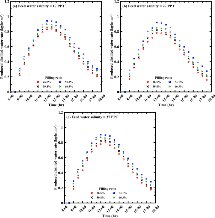
Effect of filling ratio on solar still distilled water rate for different feed water salinities of a 17 PPT, b 27 PPT, and c 37 PPT
Figure 10 demonstrates the effect of varying the filling ratio on the system's cumulative productivity. Increasing the filling ratio of the still from 26.5% up to 53.1% boosted the daily cumulative productivity but it was reduced at 66.3% filling ratio. The daily cumulative productivity at 17 ppt feed water salinity was 5, 5.23, 6, and 5.63 kg/m 2 for filling ratios of 26.5, 39.8, 53.1, and 66.3%, respectively.
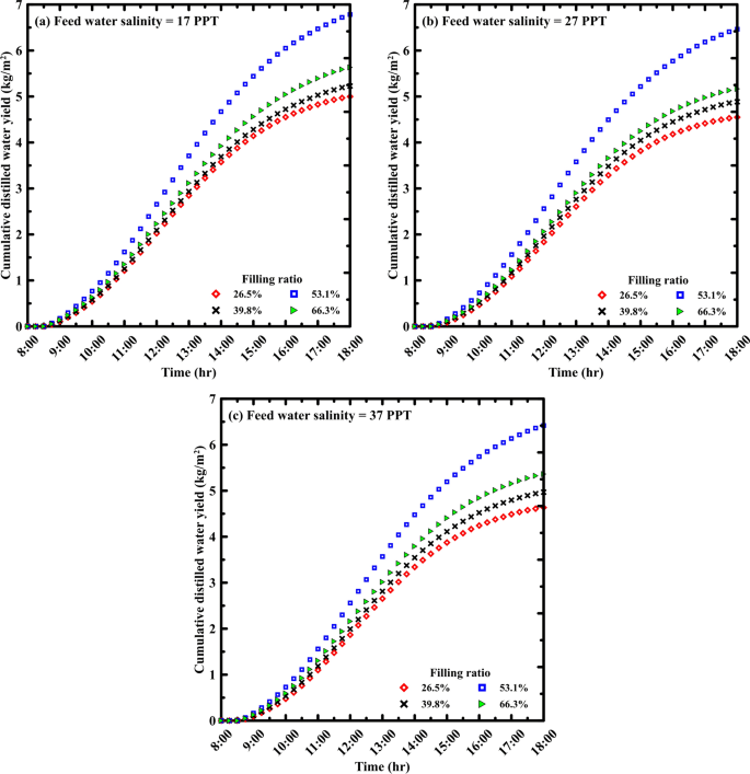
Effect of filling ratio on solar still daily cumulative productivity for different feed water salinities of a 17 PPT, b 27 PPT, and c 37 PPT
The instantaneous efficiency for different filling ratios is illustrated in Fig. 11 ; it is computed from the hourly distilled water and solar energy using Eq. ( 13 ). According to the figures, raising the filling ratio from 26.5 to 53.1% enhanced instantaneous efficiency, whereas increasing the filling ratio to 66.3% lowered it. The instantaneous efficiency gradually ascends until it reaches a maximum between 12:00 and 13:00, when the distilled water was at its peak, and then it progressively drops through the rest of test hours. Until the final period of 17:00 to 18:00, when the instantaneous efficiency remains constant or slightly increases, when the DNI drops and the generation of vapor and production of distilled water based on the heat energy stored inside the solar still. The instantaneous efficiencies at 12:00 for a feed water salinity of 17 ppt were 53.11, 54.31, 61.77, and 57.59%, for filling ratios of 26.5, 39.8, 53.1, and 66.3%, respectively.
Effect of filling ratio on instantaneous efficiency for different feed water salinities of a 17 PPT, b 27 PPT, and c 37 PPT
Effect of varying feed water salinity
The effect of salinity was studied in the range of 17–37 ppt with 10 ppt increments, and the results showed that distilled productivity and system efficiency were insignificantly reduced with salinity increase, which is considered beneficial for the proposed desalinating system because it can desalinate not only brackish or saline water but also highly saline and brine water. The boiling temperature elevates with increased salinity requiring more energy to evaporate the saline water. Furthermore, raising the salinity of the feed water causes precipitated salts to accumulate on the absorber plate surface over time, acting as insulation for heat transfer into the solar still.
The rate of distilled water for various feed water salinities ranging from 17 to 37 ppt is shown in Fig. 12 . The results demonstrated that a higher distilled water rate was achieved by the lowest salinity 17 ppt, whereas the 27 and 37 ppt salinities were remarkably closely explained by the lower average solar irradiance during the experiments on the 27 ppt sample. As described in the previous section where the distilled water rate curve can be divided into three periods, period of energy buildup from 9:00 to 13:00, period of peak evaporation from 11:30 to 13:30, finally period of decline from 14:00 to 18:00. The distilled water rate at 12:30 at a filling ratio of 26.5%, was 0.838, 0.777, and 0.81 kg/hr.m 2 for feed water salinities of 17, 27, and 37 ppt, respectively.
Effect of feed water salinity on solar still distilled water rate for different filling ratios of a 26.5%, b 39.8%, c 53.1%, d 66.3%
Figure 13 depicts the effect of feed water salinity on distilled cumulative productivity of the system. Raising the feed water salinity reduces the cumulative productivity. Raising the feed water salinity from 17 ppt to 27 and 37 ppt, lowered the cumulative productivity from 6 to 5.72 and 5.68 kg/m 2 , respectively, at filling ratio of 53.1%.
Effect of feed water salinity on solar still daily cumulative productivity for different filling ratios of a 26.5%, b 39.8%, c 53.1%, d 66.3%
The instantaneous efficiency calculated from Eq. ( 13 ) for various feed water salinities is illustrated in Fig. 14 . The instantaneous efficiency is relatively similar with minor differences, but it insignificantly decreased by increasing the feed water salinity. It can be seen that the efficiency remains constant or slightly increase in the period of 17:00 to 18:00 due to the drop in DNI and vapor generation depending on energy stored (as mentioned in the previous section). Maximum instantaneous efficiency values for filling ratio of 53.1% at 12:00 are 61.77%, 62.03%, and 59.77% for feed water salinities of 17, 27, and 37 ppt, respectively.
Effect of feed water salinity on instantaneous efficiency for different filling ratios of a 26.5%, b 39.8%, c 53.1%, d 66.3%
Figure 15 summarizes the proposed system's daily cumulative productivity and system efficiency under several operating parameters investigated. By increasing the filling ratio from 26.5 to 53.1%, daily productivity and system efficiency were on average enhanced by 22.7% and 26.3%, respectively. A further increase in the filling ratio from 53.1 to 66.3% averagely lowered daily productivity and system efficiency by 7.1% and 6.9%, respectively. On the contrary, raising the feed water salinity reduces daily cumulative productivity and system efficiency. When the feed water salinity is raised from 17 to 27 ppt, the values of daily productivity and system efficiency are reduced by 7.1% and 2.2%, respectively. The corresponding values for raising feed water salinity from 17 to 37 ppt are 5.6% and 5.1%, respectively. Taking into consideration the lower average solar irradiance during the experiments on the 27 ppt sample.
Effect of feed water salinity and filling ratio on solar still a cumulative productivity, b daily system efficiency
Economic analysis
Aside from design simplicity, ease of implementation, and component availability, the primary purpose of developing a novel solar desalinating unit is to supply pure freshwater at low cost and competitive rates to rural and isolated areas. Table 4 shows cost estimation for the proposed system's main components. The system's total fixed cost is approximately F = 231.6 $. The average cost of distilled water is calculated using Eq. ( 14 ):
where n is the expected solar still lifespan, V is the variable cost, and C is the total cost.
Previous studies used a variable cost (V) of 0.3 F per year (Omara and Eltawil 2013 ; Kabeel 2009 ) and a lifespan of 10 years for this unit, therefore \(C=231.6+0.3\times 231.6\times 10=926.4 \$\) .
Nevertheless, for a comprehensive evaluation of the system's economic viability throughout the year, the annual productivity is calculated by multiplying the average summer production by the average number of sunny days in the testing region. Sunny days annually typically range between 250 and 340 in various countries (Omara and Eltawil 2013 ; Elashmawy 2017 , 2020 , 2019 ; Elashmawy and Alshammari 2020 ; Ahmed et al. 2022 ; Wang et al. 2022 ; Abubakkar et al. 2021 ; Tawfik et al. 2022 ; Gorjian et al. 2014 ; Kabeel 2009 ; Jobrane et al. 2022 ; Dhivagar et al. 2022 ; Alqsair et al. 2022 ), while in Egypt, this range extends from 300 to 340 (Omara and Eltawil 2013 ; Tawfik et al. 2022 ; Kabeel 2009 ). In this study, the average value within the specified range for Egypt has been utilized. This daily average distilled productivity figure serves as a pivotal metric for evaluating the system's overall performance and efficiency. Furthermore, it underscores the importance of extending the analysis beyond the summer season to encompass variations in climatic conditions throughout the year. While the current data reflect operational outcomes during hot climatic conditions during summer season, it is imperative to address the system's performance during the contrasting winter season. In accordance with the experimental findings, the daily average distilled productivity of the system is established at 5.92 kg/day. Assume the distillation system operates for approximately 320 days per year, considering the consistent sunlight throughout the year in Egypt. During the system's lifespan, the total distilled yield is \(5.92\times 10\times 320=18{,}944\, {\text{kg}}\) . The cost of producing one kilogram of freshwater is \(926.4/18944=0.0489\,{\$}\) .
Egypt, situated within the Earth's Sun Belt, exhibits distinct solar energy potential throughout the year, it experiences a range of daily direct normal irradiance (DNI) from 5.6 to 7.6 kWh/m 2 , as delineated by the solar atlas. Egypt gets the most sunshine hours in June (11.9 h), the least in January (6.2 h), and an average of 9.2 h throughout the year (Climate: Nile Delta in Egypt. 2024 ). The investigation was conducted during June, and July, and August with a daily operational timeframe of 10 h, aligning with the yearly average. While the system's efficiency may dip during winter compared to summer, Egypt's substantial solar energy potential persists throughout the year, ensuring the system can maintain satisfactory water productivity even in the winter months.
Table 5 illustrates a comparison of the current study's findings with prior investigations with conventional solar stills and solar stills coupled with solar dish concentrator. The daily cumulative productivity for the current study was 6 kg/m 2 , which is within range for previous studies of concentrated solar stills (4.44–6.5 kg/m 2 ), and higher than that of CSS (1.19–4.235 kg/m 2 ). The efficiency of the solar still system increased by concentrating more solar radiation on the absorber plate leading to increasing the temperatures of the waters and reaching the boiling state and enhance the generation of vapor. The system efficiency of the proposed system was higher than that of CSS (11–31.46%), while comparing it to concentrated solar still it was higher than Tawfik ( 2022 ).
It can be seen that the concentration ratio affects the cost of the distilled water, Tawfik ( 2022 ) had less CR than the proposed system, so their system CPL was higher, while Omara (Omara and Eltawil 2013 ) had higher CR than the proposed system, so their system CPL was less; this achievement is critical for water production. Furthermore, when compared to the global average CPL of $0.474 (Bottled water 2022 ), the current study indicates an excellent CPL of water.
Conclusions and recommendations
The current study explores the experimental performance of an innovative sun tracking concentrated solar still with a solar concentration ratio of 12.5 under Egyptian weather conditions. This is to identify novel options for providing freshwater to rural areas in simple and cost-effective ways. In the summer of 2022, the system was assessed by varying two critical factors: the feed water salinity (17 ppt, 27 ppt, 37 ppt to replicate sea water in the Mediterranean Sea and brackish water in Egypt). Furthermore, the solar still filling ratios, where four ratios were assessed (26.5, 39.8, 53.1, and 66.3%), the study's primary conclusions are as follows:
Increasing the filling ratio from 26.5 to 53.1% resulted in a 22.69% increase in the daily cumulative productivity and a 26.34% boost in the daily system efficiency.
Further increase in the filling ratio from 53.1 to 66.3% has reduced the daily cumulative productivity and daily system efficiency by 7.06% and 6.87%, respectively.
Increasing the feed water salinity from 17 to 37 ppt reduced the daily cumulative productivity by approximately 5.61% while decreasing daily system efficiency by 5.1%.
The optimum solar still filling ratio is 53.1%, with a daily cumulative productivity of 6 kg/m 2 and a daily system efficiency of 42.88%.
By examining the pricing of the proposed concentrator solar still, it indicates the distinct economic feasibility, as a liter of desalinated water costs $0.0489, which is a promising price when compared to the other solar desalination technologies.
The current study indicates potential areas for further improvement, suggesting the following research opportunities:
Evaluate the device's performance under various climatic conditions throughout the year, with a specific focus on cloudy conditions to provide a more comprehensive overview.
Consider incorporating photovoltaic cells to supply the required electrical power, enhancing the device's sustainability, and reducing dependence on external power sources.
Abbreviations
Area (m 2 )
Concentration ratio
Direct normal irradiance (W/m 2 )
Shading factor
Convection heat transfer coefficient (W/m 2 K)
Water latent heat of vaporization (J/kg)
Thermal conductivity (W/m K)
Characteristic length (m)
Mass of distilled yield (kg)
Nusselt number
Heat transfer (W)
Reynolds number
Temperature (K)
Absorber outside temperature (K)
Ambient air temperature (K)
Velocity of wind (m/s)
Time interval (s)
Angle formed by the absorber plate and the vertical
Kinematic viscosity (m 2 /s)
Reflectivity
Stefan–Boltzmann constant (W/m 2 K 4 )
- Filling ratio
Uncertainty
Intercept factor
Concentrated
Cost per liter ($/L)
Conventional solar still
Phase change material
Solar dish concentrator
Abubakkar A, Selvakumar P, Rajagopal T, Tamilvanan A (2021) Development of concentrating dish and solar still assembly for sea water desalination. In: Materials Today: Proceedings, Elsevier, Amsterdam pp 974–980. https://doi.org/10.1016/j.matpr.2020.03.043 .
Ahmed MMZ, Alshammari F, Alatawi I, Alhadri M, Elashmawy M (2022) A novel solar desalination system integrating inclined and tubular solar still with parabolic concentrator. Appl Therm Eng 213:118665. https://doi.org/10.1016/j.applthermaleng.2022.118665
Article Google Scholar
Al-Amayreh MI, Alahmer A, Manasrah A (2020) A novel parabolic solar dish design for a hybrid solar lighting-thermal applications. Energy Rep 6:1136–1143. https://doi.org/10.1016/J.EGYR.2020.11.063
Al-Harahsheh M, Abu-Arabi M, Ahmad M, Mousa H (2022) Self-powered solar desalination using solar still enhanced by external solar collector and phase change material. Appl Therm Eng 206:118118. https://doi.org/10.1016/j.applthermaleng.2022.118118
Article CAS Google Scholar
Al_qasaab MR, Abed QA, Abd Al-wahid WA (2021) Enhancement the solar distiller water by using parabolic dish collector with single slope solar still. J Therm Eng 7(4):1001–1015
Aliman O, Daut I, Adzman R (2007) Simplification of sun tracking mode to gain high concentration solar energy. Am J Appl Sci 4(3):171–175
Alqsair UF, Abdullah AS, Omara ZM (2022) Enhancement the productivity of drum solar still utilizing parabolic solar concentrator, phase change material and nanoparticles’ coating. J Energy Storage. https://doi.org/10.1016/j.est.2022.105477
Alshqirate AA, Awad AS, Al Alawin A, Essa MA (2023) Experimental investigation of solar still productivity enhancement of distilled water by using natural fibers. Desalination 553:116487. https://doi.org/10.1016/j.desal.2023.116487
Amiri H, Aminy M, Lotfi M, Jafarbeglo B (2021) Energy and exergy analysis of a new solar still composed of parabolic trough collector with built-in solar still. Renew Energy 163:465–479. https://doi.org/10.1016/j.renene.2020.09.007
Bahrami M, Madadi Avargani V, Bonyadi M (2019) Comprehensive experimental and theoretical study of a novel still coupled to a solar dish concentrator. Appl Therm Eng 151:77–89. https://doi.org/10.1016/j.applthermaleng.2019.01.103
Bait O (2020) Direct and indirect solar–powered desalination processes loaded with nanoparticles: a review. Sustain Energy Technol Assessm 37:100597. https://doi.org/10.1016/j.seta.2019.100597
Bottled water—prices by country, around the world, September 2022|GlobalProductPrices.com. Accessed: Apr. 14, 2023 ( online) . Available: https://www.globalproductprices.com/rankings/mineral_water_prices/
Chaouchi B, Zrelli A, Gabsi S (2007) Desalination of brackish water by means of a parabolic solar concentrator. Desalination 217(1–3):118–126. https://doi.org/10.1016/j.desal.2007.02.009
Climate: Nile Delta in Egypt. Accessed: Jan. 20, 2024. ( online ). Available: https://www.worlddata.info/africa/egypt/climate-nile-delta.php
Coventry J, Andraka C (2017) Dish systems for CSP. Sol Energy 152:140–170. https://doi.org/10.1016/j.solener.2017.02.056
Dhivagar R, Shoeibi S, Parsa SM, Hoseinzadeh S, Kargarsharifabad H, Khiadani M (2023) Performance evaluation of solar still using energy storage biomaterial with porous surface: an experimental study and environmental analysis. Renew Energy 206(December 2022):879–889. https://doi.org/10.1016/j.renene.2023.02.097
El-Sebaey MS, Ellman A, Hegazy A, Panchal H (2022) Experimental study and mathematical model development for the effect of water depth on water production of a modified basin solar still. Case Stud Therm Eng 33:101925. https://doi.org/10.1016/j.csite.2022.101925
El-Sebaii AA, El-Naggar M (2017) Year round performance and cost analysis of a finned single basin solar still. Appl Therm Eng 110:787–794. https://doi.org/10.1016/j.applthermaleng.2016.08.215
Elashmawy M (2017) An experimental investigation of a parabolic concentrator solar tracking system integrated with a tubular solar still. Desalination 411:1–8. https://doi.org/10.1016/j.desal.2017.02.003
Elashmawy M (2019) Effect of surface cooling and tube thickness on the performance of a high temperature standalone tubular solar still. Appl Therm Eng 156:276–286. https://doi.org/10.1016/j.applthermaleng.2019.04.068
Elashmawy M (2020) Improving the performance of a parabolic concentrator solar tracking-tubular solar still (PCST-TSS) using gravel as a sensible heat storage material. Desalination 473:114182. https://doi.org/10.1016/j.desal.2019.114182
Elashmawy M, Alshammari F (2020) “Atmospheric water harvesting from low humid regions using tubular solar still powered by a parabolic concentrator system. J Clean Prod 256:120329. https://doi.org/10.1016/j.jclepro.2020.120329
Fayaz Z, Dhindsa GS, Sokhal GS (2021) Experimental study of solar still having variable slope tilted wick in the basin to enhance its daily yield. In: Materials today: proceedings. Elsevier, Amsterdam (2021), pp 1421–1426. https://doi.org/10.1016/j.matpr.2021.09.195
Fredriksson J, Eickhoff M, Giese L, Herzog M (2021) A comparison and evaluation of innovative parabolic trough collector concepts for large-scale application. Sol Energy 215:266–310. https://doi.org/10.1016/j.solener.2020.12.017
Global Solar Atlas (2023) Accessed: Mar. 29, 2023. ( online) . Available: https://globalsolaratlas.info/download/egypt
Gorjian S, Ghobadian B, Tavakkoli Hashjin T, Banakar A (2014) Experimental performance evaluation of a stand-alone point-focus parabolic solar still. Desalination 352:1–17. https://doi.org/10.1016/j.desal.2014.08.005
Holman JP. Experimental methods for engineers eighth edition. ( online) . Available: www.mhhe.com/holman
Jamar A, Majid ZAA, Azmi WH, Norhafana M, Razak AA (2016) A review of water heating system for solar energy applications. Int Commun Heat Mass Transf 76:178–187. https://doi.org/10.1016/J.ICHEATMASSTRANSFER.2016.05.028
Jobrane M, Kopmeier A, Kahn A, Cauchie HM, Kharroubi A, Penny C (2022) Theoretical and experimental investigation on a novel design of wick type solar still for sustainable freshwater production. Appl Therm Eng 200:117648. https://doi.org/10.1016/j.applthermaleng.2021.117648
Kabeel AE (2009) Performance of solar still with a concave wick evaporation surface. Energy 34(10):1504–1509. https://doi.org/10.1016/j.energy.2009.06.050
Luo Y, Lu T, Du X (2018) Novel optimization design strategy for solar power tower plants. Energy Convers Manag 177:682–692. https://doi.org/10.1016/j.enconman.2018.09.089
Muthu Manokar A et al (2020) Effect of water depth and insulation on the productivity of an acrylic pyramid solar still—an experimental study. Groundw Sustain Dev 10:100319. https://doi.org/10.1016/j.gsd.2019.100319
Omara ZM, Eltawil MA (2013) Hybrid of solar dish concentrator, new boiler and simple solar collector for brackish water desalination. Desalination 326:62–68. https://doi.org/10.1016/j.desal.2013.07.019
Panchal H et al (2021) Graphite powder mixed with black paint on the absorber plate of the solar still to enhance yield: An experimental investigation. Desalination 520:115349. https://doi.org/10.1016/j.desal.2021.115349
Perini S, Tonnellier X, King P, Sansom C (2017) Theoretical and experimental analysis of an innovative dual-axis tracking linear Fresnel lenses concentrated solar thermal collector. Sol Energy 153:679–690. https://doi.org/10.1016/j.solener.2017.06.010
Prado GO, Vieira LGM, Damasceno JJR (2016) Solar dish concentrator for desalting water. Sol Energy 136:659–667. https://doi.org/10.1016/j.solener.2016.07.039
Qtaishat MR, Banat F (2013) Desalination by solar powered membrane distillation systems. Desalination 308:186–197. https://doi.org/10.1016/j.desal.2012.01.021
Rahmani A, Khemmar F, Saadi Z (2021) Experimental investigation on the negative effect of the external condenser on the conventional solar still performance. Desalination 501(August 2020):114914. https://doi.org/10.1016/j.desal.2020.114914
Renewable Energy|Department of Energy.” Accessed: Mar. 29, 2023. ( online) . Available: https://www.energy.gov/eere/renewable-energy
Sakthivadivel D, Balaji K, Dsilva Winfred Rufuss D, Iniyan S, Suganthi L (2020) Solar energy technologies: principles and applications. In: Renewable-energy-driven future: technologies, modelling, applications, sustainability and policies. Elsevier, Amsterdam, pp 3–42. https://doi.org/10.1016/B978-0-12-820539-6.00001-7
Shatat M, Riffat SB (2014) Water desalination technologies utilizing conventional and renewable energy sources. Int J Low-Carbon Technol 9(1):1–19. https://doi.org/10.1093/ijlct/cts025
Tawfik MA, El-Tohamy M, Metwally AA, Khallaf AM, Abd Allah WE (2022) Experimental and numerical investigation of thermal performance of a new design solar parabolic dish desalination system. Appl Therm Eng 214:118827. https://doi.org/10.1016/j.applthermaleng.2022.118827
Tian Y, Zhao CY (2013) A review of solar collectors and thermal energy storage in solar thermal applications. Appl Energy 104:538–553. https://doi.org/10.1016/J.APENERGY.2012.11.051
Velmurugan V, Deenadayalan CK, Vinod H, Srithar K (2008) Desalination of effluent using fin type solar still. Energy 33(11):1719–1727. https://doi.org/10.1016/j.energy.2008.07.001
Wang L, Ma X, Zhao Y, Jin R, Zheng H (2022) Performance study of a passive vertical multiple-effect diffusion solar still directly heated by parabolic concentrator. Renew Energy 182:855–866. https://doi.org/10.1016/j.renene.2021.09.074
Download references
Acknowledgements
The authors would like to thank the Combustion and energy technology lab at Benha University's Shoubra faculty of engineering for providing technical assistance and experimental tools for this study.
Open access funding provided by The Science, Technology & Innovation Funding Authority (STDF) in cooperation with The Egyptian Knowledge Bank (EKB).
Author information
Authors and affiliations.
Combustion and Energy Technology Lab, Mechanical Engineering Department, Shoubra Faculty of Engineering, Benha University, 108 Shoubra Street, Cairo, Egypt
Mohammad M. Daif, Mohamed Emam, M. A. Abdelrahman, Ahmed A. A. Attia & Aly M. A. Soliman
Department of Energy Resources Engineering, Egypt-Japan University of Science and Technology (E-JUST), Alexandria, 21934, Egypt
Mohamed Emam
Faculty of Engineering, King Salman International University, South Sinai, El-Tor, 46511, Egypt
Aly M. A. Soliman
You can also search for this author in PubMed Google Scholar
Corresponding authors
Correspondence to Ahmed A. A. Attia or Aly M. A. Soliman .
Ethics declarations
Conflict of interest.
The authors declare that they have no known competing financial interests or personal relationships that could have appeared to influence the work reported in this paper.
informed consent
There are no human or animal participants in our research.
Rights and permissions
Open Access This article is licensed under a Creative Commons Attribution 4.0 International License, which permits use, sharing, adaptation, distribution and reproduction in any medium or format, as long as you give appropriate credit to the original author(s) and the source, provide a link to the Creative Commons licence, and indicate if changes were made. The images or other third party material in this article are included in the article's Creative Commons licence, unless indicated otherwise in a credit line to the material. If material is not included in the article's Creative Commons licence and your intended use is not permitted by statutory regulation or exceeds the permitted use, you will need to obtain permission directly from the copyright holder. To view a copy of this licence, visit http://creativecommons.org/licenses/by/4.0/ .
Reprints and permissions
About this article
Daif, M.M., Emam, M., Abdelrahman, M.A. et al. Experimental investigation of a sun tracking concentrated solar still with economic analysis. Appl Water Sci 14 , 136 (2024). https://doi.org/10.1007/s13201-024-02182-7
Download citation
Received : 14 October 2023
Accepted : 16 April 2024
Published : 20 May 2024
DOI : https://doi.org/10.1007/s13201-024-02182-7
Share this article
Anyone you share the following link with will be able to read this content:
Sorry, a shareable link is not currently available for this article.
Provided by the Springer Nature SharedIt content-sharing initiative
- Concentrated solar still
- Saline water
- Desalination
- Find a journal
- Publish with us
- Track your research

COMMENTS
Solar Photovoltaic technology deals with conversion of incident sunlight energy into electrical energy. Solar cells fabricated from Silicon aie the first generation solar cells. It was studied that more improvement is needed for large absorption of incident sunlight and increase in efficiency of solar cells.
This paper reviews the advancement made in the previous years in the field of monocrystalline, polycrystalline and thin-film PV and perovskite solar cell. This paper provides a general understanding of power generation using PV systems and discusses early research of the PV cell.
ogy in the solar cell research and development. The main principle o f concentrated cells is to collect a large amount of solar ener gy onto a tiny region over the PV solar cel l, as shown in Fig ...
Here, we present an analysis of the performance of 'champion' solar cells (that is, cells with the highest PCE values measured under the global AM 1.5 spectrum (1,000 W m −2)) for different ...
Solar energy is free from noise and environmental pollution. It could be used to replace non-renewable sources such as fossil fuels, which are in limited supply and have negative environmental impacts. The first generation of solar cells was made from crystalline silicon. They were relatively efficient, however very expensive because they require a lot of energy to purify the silicon. Nowadays ...
Roll-to-Roll (R2R) coating is a technology that potentially enhances throughput, reduces costs, and accommodates flexible substrates for fabricating various types of solar cells and modules.
10.47750/pnr.202 2.13.S06.268. In this review paper, we highlight about the generations and types of solar cells. The developm ent in solar cells have seen a rapid. advancement in the efficiency ...
Usually, these panels are able to absorb light in the visible area (different colors have different amounts of energy). Thin-film solar cells can absorb a wider range of wavelengths (400-1100 nm) when compared with crystalline silicon solar cells (850 nm). Solar panels can produce electricity from sunlight.
Solar technology refers to technology that uses solar radiation to generate electricity or utilize thermal energy. Solar energy is environmentally friendly, renewable, noiseless, and pollution-free and does not require fuel, making it a form of renewable energy. A solar cell (SC) comprises multiple thin layers of semiconductor materials. When sunlight shines on an SC, photons excite electrons ...
Employing sunlight to produce electrical energy has been demonstrated to be one of the most promising solutions to the world's energy crisis. The device to convert solar energy to electrical energy, a solar cell, must be reliable and cost-effective to compete with traditional resources. This paper reviews many basics of photovoltaic (PV) cells, such as the working principle of the PV cell ...
This type of solar c ell design technology allows larger abs orb ance of solar spectrum thus increasing photon convers ion efficiency. A solar cell having an inf inite number of junctions would have a
This paper presents a model that is first of its kind where the highest PCE performance and eco-friendly n-type TCO-free inverted CH3NH3SnI3 based perovskite solar cell is achieved using all ...
Perovskite solar cells (PSC) have been identified as a game-changer in the world of photovoltaics. This is owing to their rapid development in performance efficiency, increasing from 3.5% to 25.8% in a decade. Further advantages of PSCs include low fabrication costs and high tunability compared to conventional silicon-based solar cells. This paper reviews existing literature to discuss the ...
Accordingly, the air processed perovskite solar cells based on compact-In 2 O 3 film exhibits high PCE of 13.97% whereas pristine In 2 O 3 -film shows the PCE of 9.81%. Along with high PCE the proposed indium-based perovskite solar cell shows long term stability and retains 94% of its PCE even after 31 days of storage.
The photovoltaic effect is used by the photovoltaic cells (PV) to convert energy received from the solar radiation directly in to electrical energy [3].The union of two semiconductor regions presents the architecture of PV cells in Fig. 1, these semiconductors can be of p-type (materials with an excess of holes, called positive charges) or n-type (materials with excess of electrons, called ...
The purpose of this paper is to discuss the different generations of photovoltaic cells and current research directions focusing on their development and manufacturing technologies. The introduction describes the importance of photovoltaics in the context of environmental protection, as well as the elimination of fossil sources.
Solar cells, Solar energy. Organic solar cells (OSCs) have been recognized to have tremendous potential as alternatives to their inorganic counterparts, with devices that are low-cost, lightweight, and easily processed and have less environmental impact. Challenges for OSCs to be utilized commercially on a large scale have been highlighted by ...
1. Introduction. In the context of global energy transformation, solar cells have attracted much attention as a clean and renewable energy conversion technology [1].However, traditional organic-inorganic hybrid perovskite solar cells are limited in large-scale commercial applications due to limitations in stability and cost [2, 3].In order to overcome these challenges, all-inorganic perovskite ...
Abstract and Figures. In this review, principles of solar cells are presented together with the photovoltaic (PV) power generation. A brief review of the history of solar cells and present status ...
Abstract: Energy harvesting using solar cells is a domain that has received a lot of interest and improvement in the recent years. Various techniques and new materials have been proposed in order to attain this purpose. Our paper has the goal to present the main types of solar cells, comparing their advantages and shortcomings, together with the most recent technologies proposed for energy ...
Abstract. This review is focused on the current development in domain of organic photovoltaic cells (OPVs). Solar cells play a vital role for electricity production by converting sunlight to electric current. This paper presents an exhaustive literature review on advancements in field of OPVs. The solar cells, as a substitute for fossil fuels ...
Dye-sensitized solar cells (DSSCs) belong to the group of thin-film solar cells which have been under extensive research for more than two decades due to their low cost, simple preparation methodology, low toxicity and ease of production. Still, there is lot of scope for the replacement of current DSSC materials due to their high cost, less abundance, and long-term stability. The efficiency of ...
Popular Science reporter Andrew Paul writes that MIT researchers have developed a new ultra-thin solar cell that is one-hundredth the weight of conventional panels and could transform almost any surface into a power generator. The new material could potentially generate, "18 times more power-per-kilogram compared to traditional solar technology," writes Paul.
A one-dimensional simulation programme called SCAPS-1D was designed at the University of Gent in Belgium. It has been used to research several solar cell types, including CZTS, CdTe, CIGS, etc. [61, 62]. When compared to other software, SCAPS-1D features a very user-friendly operation window and a variety of models for grading, faults, and ...
What is solar energy? Solar energy refers to the electrical or thermal energy that is created from solar radiation—the power of the sun. Solar energy is also called solar power, or even just ...
Bottom line. There are four main types of solar panels: Monocrystalline, polycrystalline, thin-film and solar shingles. Each has its benefits and drawbacks, and the best solar panel for your needs ...
The current paper evaluated experimentally an innovative sun tracking concentrated solar still under Egyptian climatic conditions during the summer of 2022. The proposed system consists of a 120-cm-diameter parabolic reflector mirror that tracks the sun using a dual axis tracking system, a cylindrical solar still with a volume of 3.7 L positioned in its focal point, and a concentration ratio ...