FREE K-12 standards-aligned STEM
curriculum for educators everywhere!
Find more at TeachEngineering.org .
- TeachEngineering
- Connect the Dots: Isometric Drawing and Coded Plans

Hands-on Activity Connect the Dots: Isometric Drawing and Coded Plans
Grade Level: 7 (7-9)
Time Required: 1 hour
This activity requires some non-expendable (reusable) snap cubes; see the Materials List for details.
Group Size: 2
Activity Dependency: Let’s Learn about Spatial Viz!
Subject Areas: Geometry, Problem Solving
Activities Associated with this Lesson Units serve as guides to a particular content or subject area. Nested under units are lessons (in purple) and hands-on activities (in blue). Note that not all lessons and activities will exist under a unit, and instead may exist as "standalone" curriculum.
- Seeing All Sides: Orthographic Drawing
- Let’s Take a Spin: One-Axis Rotation
- New Perspectives: Two-Axis Rotations
TE Newsletter
Engineering connection, learning objectives, materials list, worksheets and attachments, more curriculum like this, pre-req knowledge, introduction/motivation, vocabulary/definitions, activity extensions, activity scaling, additional multimedia support, user comments & tips.

Spatial visualization is an essential skill in taking ideas that initially only exist in the mind to something that can be communicated clearly to other people and eventually turned into products, structures and systems. As such, it is an important skill for professionals within the science, technology, engineering and math (STEM) fields—particularly engineering. Engineers use spatial visualization skills whenever three-dimensional concepts, devices and ideas are being discussed. For example, chemical engineers use spatial visualization when studying three-dimensional molecules, while mechanical engineers use spatial visualization when designing prosthetic limbs that require multiple motors, gears, linkages, bearings and shafts to fit within a single assembly.
After this activity, students should be able to:
- Draw a coded plan from an object made of cubes.
- Use a coded plan to build an object made of cubes.
- Define and explain the meaning of isometric.
- Draw a shape on isometric triangle-dot paper.
Educational Standards Each TeachEngineering lesson or activity is correlated to one or more K-12 science, technology, engineering or math (STEM) educational standards. All 100,000+ K-12 STEM standards covered in TeachEngineering are collected, maintained and packaged by the Achievement Standards Network (ASN) , a project of D2L (www.achievementstandards.org). In the ASN, standards are hierarchically structured: first by source; e.g. , by state; within source by type; e.g. , science or mathematics; within type by subtype, then by grade, etc .
Common core state standards - math.
View aligned curriculum
Do you agree with this alignment? Thanks for your feedback!
State Standards
Colorado - math.
Each group needs:
- 10 snap cubes (interlocking cubes); a set of 100 for $10-13 at https://www.amazon.com/Learning-Resources-LER4285-Mathlink-Cubes-100/dp/B000URL296 or https://www.amazon.com/Learning-Resources-LER7584-Snap-Cubes/dp/B000G3LR9Y
- pencil with eraser, for each student
- Blank Triangle-Dot Paper , two sheets per student
- Isometric Drawing Worksheet , one per student
- (optional) computer with Internet access, to practice using the NCTM online isometric drawing tool at http://illuminations.nctm.org/Activity.aspx?id=4182
To share with the entire class:
- (optional) computer with projector to show examples as provided in the Spatial Visualization Presentation , a PowerPoint® file; alternatively, draw or print out the examples for students
Before taking part in this spatial visualization activity, students should have taken the Spatial Visualization Practice Quiz and learned about spatial visualization in the associated lesson, Let’s Learn about Spatial Viz!
(Have the slide presentation up and displayed to the class, starting with slide 3.) Spatial visualization is useful for practicing engineers, has been shown to be a significant predictor of success for students in engineering, and is also a learned skill. That means we can improve our spatial visualization skills by practicing. Today, we are going develop our skills in drawing three-dimensional objects. Spatial visualization skills help you in many subjects and hobbies that require the imagination of three-dimensional shapes, such as geometry, chemistry, physics, athletics (like tennis and gymnastics) and various computer games. Practicing spatial visualization enables you to understand three-dimensional figures and representations more readily and perform better in these subjects and hobbies.
Part 1: Isometric Drawings
In the planning phase of any engineering project, an engineer needs to be able to take the vision of a new design from inside their head and illustrate it on a piece of paper or a computer screen. This process—visualizing the item as a three-dimensional object—includes the dimensions of depth, width and height. Without spatial visualization skills, engineers would be unable to envision new ideas and communicate these ideas to others.
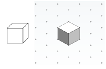
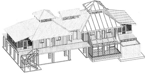
Isometric views are useful for displaying three-dimensional objects on a two-dimensional piece of paper. More specifically, we use triangle-dot paper to draw objects isometrically. (Display slide 4, which is the same as Figure 1.) This image shows a 3-D cube depicted in two different ways. On the left, the cube is drawn non-isometrically in that the angles in the corners are not equal and the sides each have different areas. However, on the right, the cube is drawn such that the sides of the cube connect at a “corner,” making equal angles of 120°. We call this an isometric view of the cube. Also notice that in the illustration on the right, all the sides of the cube are the same size. During this activity, we are going to practice drawing shapes isometrically. (Slide 5, same as Figure 4, shows a house depicted isometrically using AutoCAD.)
Part 2: Coded Plans
Next, we are going to learn about coded plans. Before explaining coded plans, let’s do an activity that demonstrates the importance of using coded plans. First, team up with a person next to you.
(Direct the class through the following exercise: Have partner #1 close their eyes. Show all partner #2 students the left image in slide 6, which is the same as Figure 2. Inform partner #1 to keep their eyes closed while partner #2 describes the image. Let the object description continue for a couple of minutes. When finished, have partner #1 draw the object as accurately as possible.)
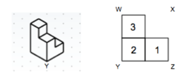
For such a simple-appearing object, that was pretty challenging, right? Perhaps you described the object using phrases like these:
- It is made of six cubes.
- Three cubes are stacked, one on top of the other. Next to that are two cubes, also stacked one on top of the other. Next to that stack is one single cube.
Even with this explanation, it is possible that your partner incorrectly envisioned the object. Imagine if you were an engineer who needed to design a much more complicated object than the one you tried to describe—it would be even more difficult! This is precisely why we use coded plans in engineering drawings. Coded plans are a type of tool used by engineers to express three-dimensional objects on two-dimensional surfaces. A coded plan defines the shape of a structure or object composed of blocks. (Click to reveal the right side of slide 6, which is the same as the right side of Figure 2—a coded plan of the same image just described and drawn by students.) For instance, a coded plan is shown here. Notice that the corners of the object are labeled by letters. Notice also that the numbers inside the squares represent the number of cubes that are stacked on top of each other. Next, we will do some activities to practice making coded plans and isometric drawings.
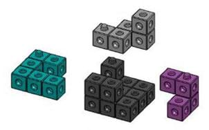
The term “isometric” literally means “equal measure.” In other words, when we isometrically draw an object composed of multiple cubes, the cube faces are all the same area and the corner angles are all equal and 120°. Triangle-dot paper is useful because the dots are situated 120° from each other, which facilitates drawing 3-D objects. For students just starting to practice spatial visualization, it is beneficial to use toy blocks with the ability to interlock and form larger shapes composed of the cubes (such as the recommended “snap cubes” in the Materials List; see Figure 3.)
Engineers use computer-aided drafting software programs such as AutoCAD® to create blueprints and design plans. Figure 4 (also on slide 5) shows a house that was depicted isometrically using AutoCAD.
Before the Activity
- Gather materials and make copies of the Blank Triangle-Dot Paper and Isometric Drawing Worksheet .
- (optional) Decide if you want to incorporate having students practice with the NCTM online isometric drawing tool that enables them to draw their own isometric objects and rotate the objects around the x-, y- and z-planes.) If so, arrange for and set up computer and Internet access to do so.
- Prepare to project the Spatial Visualization Presentation , a PowerPoint® file, and use its content to aid in your instruction, as makes sense for your class. Slides 3-11 support this activity. The slides are animated so a mouse or keyboard click brings up the next graphic or text.
With the Students: Introduction
- Present to the class the Introduction/Motivation content, supported by slides 3-6. Also ask the pre-assessment question, as described in the Assessment section.
- Divide the class into groups of two students each.
- Hand out two pieces of triangle dot paper to each student and 10 cubes to each pair. Explain that students are to share their interlocking cubes with their partners, primarily work independently on their drawings, but feel free to share their drawings and troubleshoot with their partners. Instruct students to work on one piece of triangle-dot paper until it is full.
Part 1. Basics of Drawing Cubes on Triangle-Dot Paper
- As a class, direct students to each put one cube on the desk in front of themselves. Ask the students to draw their cubes on isometric paper (individually). To begin with, direct them to move sequentially through the drawing using the following steps. (As makes sense, also show the drawing tips on slide 7.)
- Draw a dot representing a corner of the cube.
- Draw lines that represent the edges of the cube that connect to that corner.
- Draw a single surface of the cube.
- Complete all other surfaces of the cube.
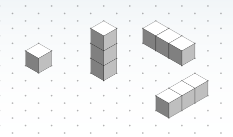
Have students stack two blocks on top of the original block to form a three-cube “tower.” Ask them to draw the stacked cubes on isometric paper and then share with their partners. Expect their drawings to resemble the center image in slide 8 (same as Figure 5-center; click the mouse/keyboard to reveal it).
Finally, have students turn their towers on their sides so that three cubes are touching the desk/table surface. Now, ask the students to draw the stacked tower at this angle on isometric paper. Expect their drawings to resemble one of the two images on the right side of slide 8 (same as Figure 5-far right; click the mouse/keyboard to reveal it), depending on which way they oriented the object.
At this point, stop and make sure that all students are getting the hang of drawing on isometric triangle-dot paper. If students are struggling, spend more time on the first three steps. If necessary, display the answers for the class and/or demonstrate how to draw each of the three images. Notice how the faces in between the cubes and the backside/bottom of each cube are not drawn directly; we know that those sides are part of the cubes, but the isometric drawing cannot depict all details of a 3-D object.
Part 2. Drawing Shapes of Increased Complexity on Triangle-Dot Paper
- Direct the students to each use four blocks to make a shape of their choosing.
- Ask the students to individually draw the shapes of their objects on isometric paper.
- Have partners switch objects and draw the shape of their partners’ objects.
- Once both partners are finished drawing the objects they created, as well as the objects created by their partners, have them cross-check their drawings to make sure that they are correct.
- Have students repeat the four previous steps, adding one more block to their shapes for each iteration. Permit students to continue working for about five minutes. If they are working through these steps quickly, see the Extension Activities section for ways to challenge them further.
- Assign students to complete the worksheet. Observe and assist as necessary.
(optional) Part 3. Drawing Isometric Views from Coded Plans
As an optional/extra credit assignment, present to students the following peer teach exercise:
- Still in pairs, show students the drawing tips on slide 9.
- Then show students the coded plan shown to the far left on slide 10 (same as Figure 6-far left. Ask them to draw two different isometric views of the coded plan. It may be necessary to rotate a sample cube shape to help students to understand this challenge. Click on slide 10 to reveal the solutions to the four possible isometric views.
- Once each student has drawn two isometric views, have student pairs explain to each other how they produced their drawings.

coded plan: A spatial visualization term that refers to a method of describing a three-dimensional shape two-dimensionally.
isometric: Of or having equal dimensions. The isometric view of an object is the angle at which an equal angle (120°) exists between all axes (such as looking down a corner of the object).
spatial visualization: The ability to mentally manipulate two- and three-dimensional objects. It is typically measured with cognitive tests and is a predictor of success in STEM fields. Also referred to as visual-spatial ability.
triangle-dot paper: A grid of dots arranged equidistant from one another. Used in making isometric sketches. Also called isometric paper.
Pre-Activity Assessment
Question/Answer: Ask students: Why are isometric drawings important to engineers? (Point to make: Isometric drawings represent three-dimensional objects on a two-dimensional surface. By doing this, engineers can depict complicated 3-D objects in a way that is easy to share and describe. Without isometric drawings, engineers would require 3-D models of each idea/concept, which would be costly, cumbersome and inconvenient.)
Activity Embedded Assessment
Worksheet: After completing the classroom instruction on isometric drawing, assign students to complete the Isometric Drawing Worksheet . Observe whether students are able to draw the rotated objects or if they are struggling. Assist them if necessary. Review their answers to gauge their depth of understanding.
Post-Activity Assessment
Discussion: Ask students to explain and describe their drawings with specific focus on the isometric concept. What strategies did they use to draw their cube shapes? What were the limitations they experienced, if any? How did students solve any drawing challenges? Since everyone has worked through the same exercises, group sharing of their challenges and approaches informs the teacher of students’ depth of understanding and provides their peers with relevant ideas and tips.
- Have students rotate one of their snap block objects to see how many new angles they can draw it from. Show slide 11 (same as Figure 7) as an example.
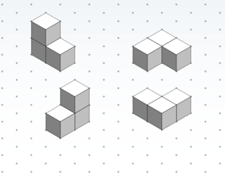
- Have students rotate a shape in their minds and draw it on triangle-dot paper without physically rotating any cubes/shapes.
- Have each partner use four cubes to make a shape and place the object under their partners’ chairs without showing the shape. Then, have students reach under their chairs and feel the objects (without looking at them) and draw the shapes they felt. Once finished, have them compare their drawings to the objects.
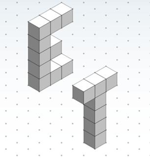
- Have students draw the capital letters E and T in isometric view; show slide 11 as an example (same as Figure 8).
- Ask students to calculate the volume and surface area of one of the shapes they drew. To help with the challenge, tell them that the length of one side of a cube is 5 cm.
- For lower grades, guide students through drawing the cube shapes by using an overhead projector. Depending on how much guidance is needed, repeat Part 1 for other very simple shapes.
- For higher grades, challenge students to conduct all the Activity Extensions.
Have students practice with the NCTM online isometric drawing tool to draw isometric objects and rotate the objects around the X, Y and Z planes: http://illuminations.nctm.org/Activity.aspx?id=4182 .

Students learn how to create two-dimensional representations of three-dimensional objects by utilizing orthographic projection techniques. They build shapes using cube blocks and then draw orthographic and isometric views of those shapes—which are the side views, such as top, front, right—with no de...

In this lesson, students are introduced to the concept of spatial visualization and measure their spatial visualization skills by taking the provided 12-question quiz. Following the lesson, students complete the four associated spatial visualization activities and then re-take the quiz to see how mu...

Students learn about one-axis rotations, and specifically how to rotate objects both physically and mentally to understand the concept. They practice drawing one-axis rotations through a group exercise using cube blocks to create shapes and then drawing those shapes from various x-, y- and z-axis ro...

Students learn about two-axis rotations, and specifically how to rotate objects both physically and mentally about two axes. Students practice drawing two-axis rotations through an exercise using simple cube blocks to create shapes, and then drawing on triangle-dot paper the shapes from various x-, ...

Contributors
Supporting program, acknowledgements.
This activity was developed by the Engineering Plus degree program in the College of Engineering and Applied Science at the University of Colorado Boulder.
This lesson plan and its associated activities were derived from a summer workshop taught by Jacob Segil for undergraduate engineers at the University of Colorado Boulder. The activities have been adapted to suit the skill level of middle school students, with suggestions on how to adapt activities to elementary or, in some instances, high school level.
Last modified: October 21, 2020
Isometric drawing: a designer's guide
Everything you need to know about creating an isometric drawing.
What is isometric drawing?
Isometric drawing vs one-point perspective, how to draw an isometric cube, the benefits of isometric drawing.
Isometric drawing, sometimes called isometric projection, is a type of 2D drawing used to draw 3D objects that is set out using 30-degree angles. It's also a type of axonometric drawing, meaning that the same scale is used for every axis, resulting in a non-distorted image. Since isometric grids are pretty easy to set up, once you understand the basics of isometric drawing, creating a freehand isometric sketch is relatively simple.
This post explains all you need to know about isometric drawing. You'll learn exactly what defines an isometric drawing, how it differs from one-point perspective , what to do to get started creating your own isometric projection, and even more. Elevate your art skills further by following the tutorials in our how to draw guide (which will teach you how to draw pretty much anything).
An isometric drawing is a 3D representation of an object, room, building or design on a 2D surface. One of the defining characteristics of an isometric drawing, compared to other types of 3D representation, is that the final image is not distorted and is always to scale. This is due to the fact that the foreshortening of the axes is equal. The word isometric comes from Greek to mean 'equal measure'.
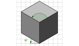
Isometric drawings are a good way to show measurements and how components fit together, and is used in technical drawing, often by engineers and architects. They differ from other types of axonometric drawing, including dimetric and trimetric projections, in which different scales are used for different axes to give a distorted final image.
In an isometric drawing, the object appears as if it is being viewed from above from one corner, with the axes set out from this corner point. Isometric drawings begin with one vertical line along which two points are defined. Any lines set out from these points should be constructed at an angle of 30 degrees.
Both isometric drawings and one-point perspective drawings use geometry and mathematics to present 3D representations on 2D surfaces. One-point perspective drawings mimic the human eye, so objects appear smaller the further away they are from the viewer. In contrast, isometric drawings use parallel projection, which means objects remain at the same size, no matter how far away they are.
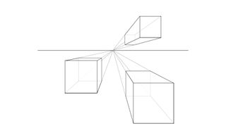
Basically, isometric drawing doesn’t use perspective in its rendering (i.e. lines don’t converge as they move away from the viewer). Isometric drawings are more useful for functional drawings that are used to explain how something works, while one-point perspective drawings are typically used to give a more sensory idea of an object or space.
Get the Creative Bloq Newsletter
Daily design news, reviews, how-tos and more, as picked by the editors.
The limitation of isometric drawings compared to 3D models is that you can't change your vantage point, you have to see the drawing from the top viewpoint.
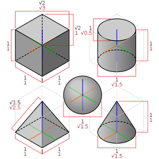
The most common isometric drawing is that of a cube, and drawing a cube using isometric projection is very easy. You will need a piece of paper, ruler, pencil and protractor (or for the shortcut version, using gridded paper, jump to the next section).
Using the ruler, draw a vertical line on the page, and mark three equally spaced points along it. Draw a horizontal line through the lowest point, and using the protractor, mark out a 30 degree angle up from the line on either side. Draw a line back through the lowest point from the 30 degree angle on each side.
Repeat this step through the middle point and the same through the top point, but with the top point, mark out the angle downwards. The lines from the second and third point will cross at a certain point, and from this intersection, draw a vertical line down towards the angled lines coming from the bottom point. You should be able to see the form of the cube where all of the lines intersect.
Using an isometric grid
For all the cheats out there who don’t have the necessary tools (or inclination) to create an isometric projection, there is a foolproof way to bash out your axonometric drawing: simply use an isometric grid. The pattern can be downloaded online, and will save you lots of time and effort, or you can have a play with the grid using this isometric drawing tool .
Alternatively, learn how to set up your own grid in Illustrator or Photoshop by following the video tutorial below.
Once your eyes become accustomed to the trickery of the triangular pattern, you will immediately notice how the isometric works. The super handy thing about the grid is that it already has all of the 30 degree angles set up for you. This tutorial walks you through how to draw a cube using an isometric grid.
Isometric drawings are very useful for designers – particularly architects, industrial and interior designers and engineers, as they are ideal for visualising rooms, products, and infrastructure. They're a great way to quickly test out different design ideas. They also illustrate the 3D nature of an object, without being drawn in 3D software , and measurements can be made to scale along the principal axes.
There are a number of other situations in which isometric projection is useful. In wayfinding systems, for example in museums or galleries, isometric wall maps can show visitors where they are in the building, what is going on elsewhere, and how to get to get around.
Some of the best infographics use isometric projection to enable them to show more information than would be possible in a 2D drawing. Some of the best logos also use this approach to create impact.
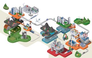
Exploded isometric drawings are useful for revealing parts of a product that might be hidden or internal. They're used by architects, engineers and product designers the world over to better explain the intricacies of a design. To create an exploded isometric, you need to know the detailed inner workings of whatever you are drawing, so they're are usually used at the final design stage for presentations to clients.
Isometric drawing examples
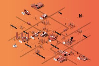
Illustrator and art director Mauco created this isometric map to represent the areas surrounding the SPECTRUM building in London. It shows just the main roads and landmarks to help people orientate themselves.

Jing Zhang is an illustrator working mainly with clients in the advertising industry. She's built a particular reputation for her detailed exploded isometric designs, including this creation for Slack. It's part of a series to accompany the brand's stories, focusing on elements such as a happy mobile workforce (above).
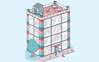
This design was created for an article in the The California Sunday Magazine, entitled The Tech Revolt and exploring political activism in the tech industry. In it, illustrator Tim Peacock uses isometric projection as a way of revealing the inner workings of a Silicon Valley office block.
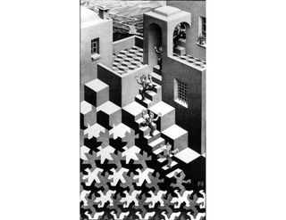
MC Escher was perhaps the king of using isometric projections in his artworks. His use of parallel geometries to depict mind-bending staircases that go nowhere will be familiar to most. In Cycle (1938), shown above, is it clear how isometric projection comes into his work, from the pattern on the ground to the use of cubes that turn into steps.
Thank you for reading 5 articles this month* Join now for unlimited access
Enjoy your first month for just £1 / $1 / €1
*Read 5 free articles per month without a subscription
Join now for unlimited access
Try first month for just £1 / $1 / €1
- Rosie Hilder
Related articles

- 2 New leaks show the iPhone 16 Pro Max is the one to get excited about
- 3 4 mind-blowing Disney animation secrets
- 4 The best drawing tablets
- 5 I can't get enough of these hilarious Photoshop retouching jobs
- 3 ASUS ProArt RTX 4060 GPU review: the new sweet spot for creatives?
- 4 4 mind-blowing Disney animation secrets
- 5 I can't get enough of this Lego Star Wars photography
Please enable JavaScript in your browser to access Amplify.
Change Language
Reset password Sign in
Create new account
Create account
Account settings
We use your Desmos Classroom account when you sign in. You can edit your account details (name, email, password), download your data, or delete your account there:
Reset password
You can reset your password on Desmos Classroom:
Isometric Drawings: Part II
Overview and objective.
In Isometric Drawings: Part 1 , students will construct the side views of the three-dimensional objects and then, they will construct the 3D objects whose side views are given.
Before starting this activity, you may want to check the Isometric Drawings Part I Task.
You may use an isometric puzzle similar to the one in the Isometric Drawings Part I Task . Show the drawing to students and ask them how many cubes they see.
Students may answer as six or seven. You may want to mark the cubes to clarify the results for all students.

Illustrators and designers often add side views to their drawings to make sure that their audience fully understands the drawings.
Main Activity
Clarify with the students that during this activity, the blue rhombus from the polygons toolbar will be used to create the unit cubes.
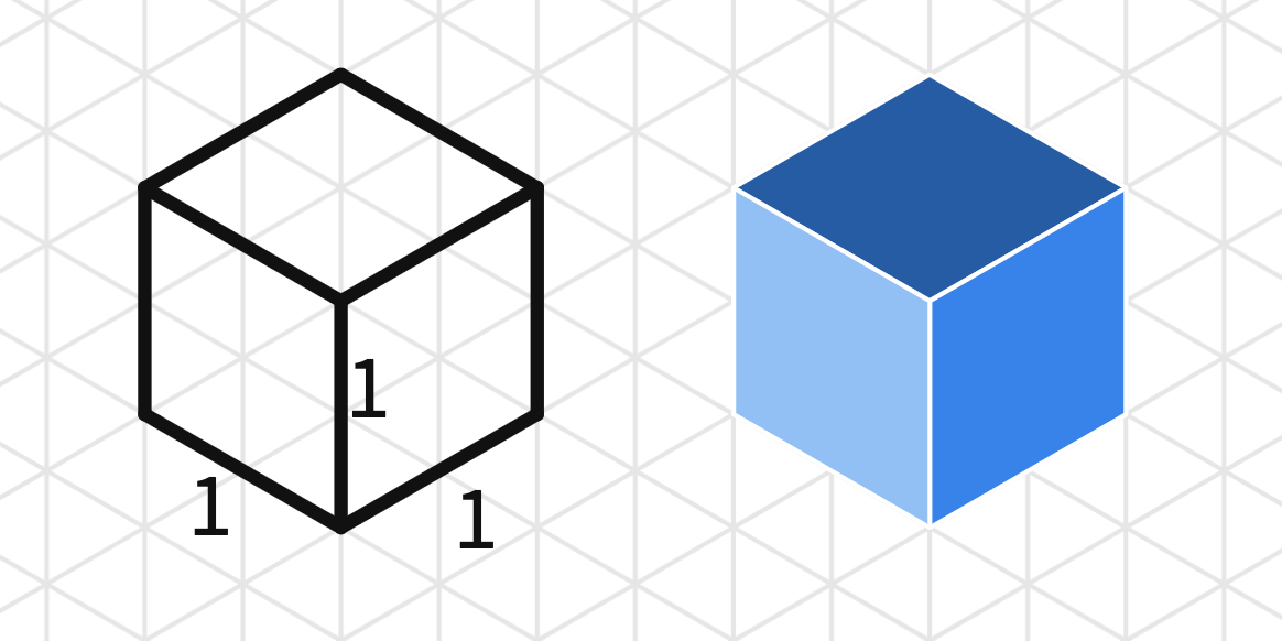
Start with the L shape (L-Prism). You may use this Polypad to demonstrate the side views of the L-shape. Think of a mirror cube surrounding the 3D object. Each mirror will only reflect the sides they are facing.
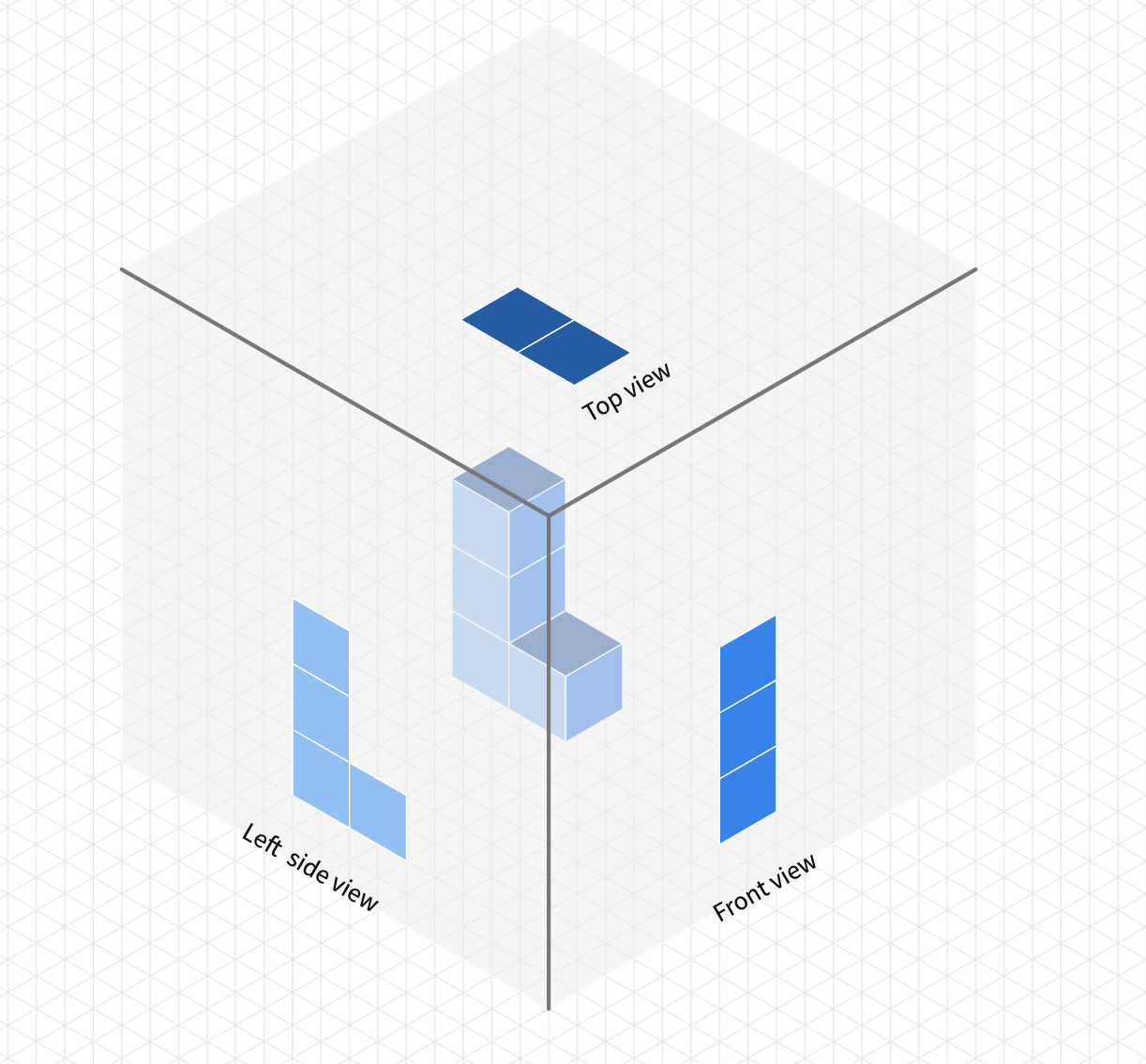
Invite students to draw the side views of another shape using the mirror cube.
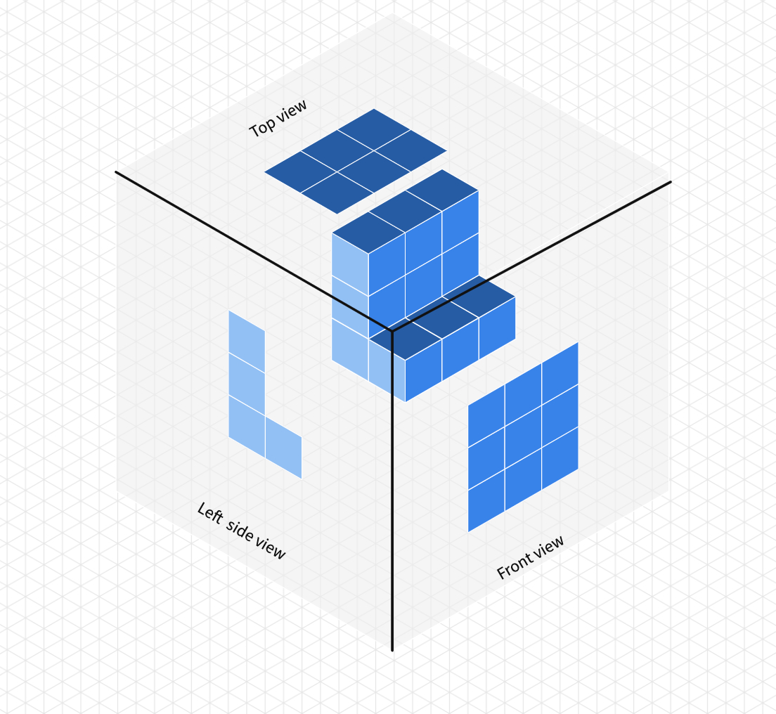
Share this Polypad with the students and ask them complete the side views of the given 3D objects.
Share some student work with the class. Invite students to share which approaches they found most useful when drawing the 3D figures.
Drawing what an object looks like from several different views is called orthographic projection. Orthographic projection is also called engineering drawings or plan views. The orthographic projection can have more than three side views if the object has unique sides that would not be fully described by three views
If an object which is not formed by unit cubes were to be drawn by the orthographic projection, additional lines are used to represent changes in depth.
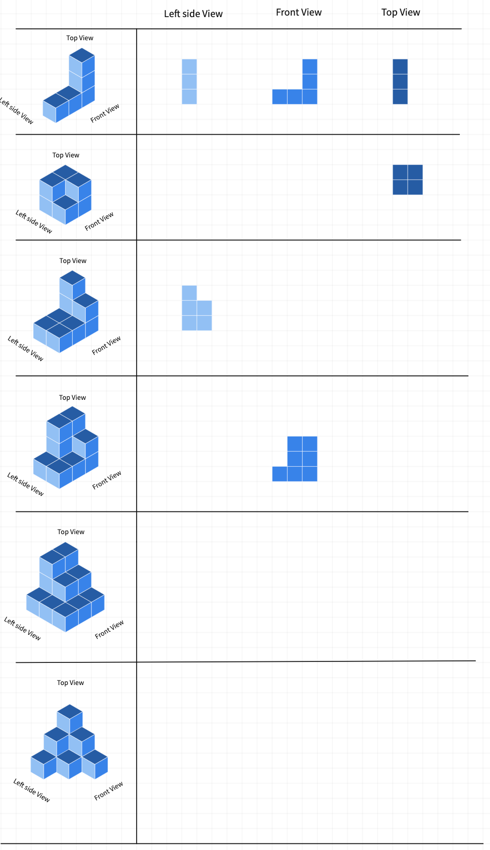
Students will now construct the 3D objects given the side views. Let students work as pairs or groups by sharing this Polypad . You may ask them to predict the number of unit cubes for each construction before they start drawing. Students can compare their predictions after each construction.
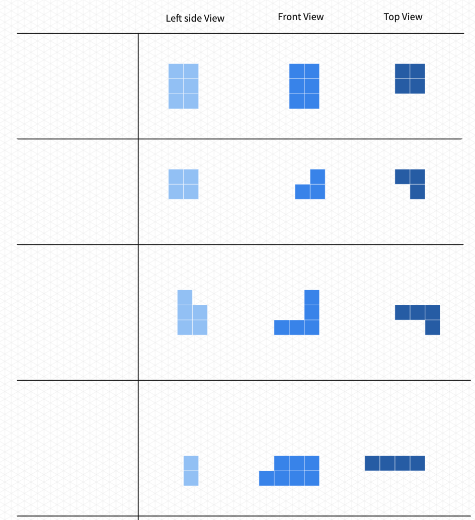
You may end the lesson by discussing that some objects may require more side views to be constructed accurately. If you have completed Isometric Drawings: Part I with the students, you may also discuss which method (number diagrams or side views) is easier to construct 3D objects.
Polypads for This Lesson
To assign these to your classes in Mathigon, save a copy to your Mathigon account.
Click here to learn how to share Polypads with students and how to view their work.

- Onsite training
3,000,000+ delegates
15,000+ clients
1,000+ locations
- KnowledgePass
- Log a ticket
01344203999 Available 24/7
What is an Isometric Drawing? Explained
Unlock the world of Isometric Drawing in this comprehensive blog, covering its definition, historical evolution, practical creation of an isometric cube, a comparison with one-point perspective, advantages, and real-world examples.

Exclusive 40% OFF
Training Outcomes Within Your Budget!
We ensure quality, budget-alignment, and timely delivery by our expert instructors.
Share this Resource
- GIMP Training
- Logo Design Course
- Essentials of Professional VLSI Digital Design Training
- Video Editing Course
- Figma Course

Isometric Drawing is a powerful method in the realm of technical and artistic representation, offering a clear and precise way to portray three-dimensional objects on a two-dimensional surface.
This blog explores What is an Isometric Drawing, delving into its history, the practical process of drawing an isometric cube, and a comparative analysis with a one-point perspective. Additionally, we'll uncover the advantages of using Isometric Drawings and provide practical examples to illustrate their diverse applications.
Table of Contents
1) What is an Isometric Drawing?
2) Isometric Drawing history
3) How to draw an isometric cube?
4) Isometric Drawing vs one-point perspective
5) Advantages of Isometric Drawing
6) Examples of Isometric Drawing
7) Conclusion
What is an Isometric Drawing?
An Isometric Drawing is a type of three-dimensional representation of an object or scene in which the three principal dimensions (length, width, and height) are presented at equal angles and distorted in such a way that lines parallel to these axes appear in their true lengths, and lines that are not parallel to these axes appear in their true lengths. In other words, an Isometric Drawing allows you to represent a three-dimensional object in two dimensions, with the angles and proportions preserved.
The term "isometric" comes from the Greek words "isos," meaning equal, and "metron," meaning measure. Isometric Drawings are often used in technical and engineering drawings to represent objects, buildings, or systems with a sense of three-dimensionality. These drawings are particularly useful for conveying a clear understanding of how different parts of a structure fit together.

Isometric Drawing history
The history of Isometric Drawing can be traced back to the early 20th century, and it has evolved over time in response to the needs of various industries. Here are some key points in the history of Isometric Drawing:
1) Early 20th century: Isometric Drawing gained popularity in the early 20th century as a way to represent three-dimensional objects in a more visually intuitive manner than traditional orthographic projections. The method became widely used in technical and engineering drawings.
2) 1911 - Patent by William F. Prout: The concept of Isometric Drawing was patented by William F. Prout in 1911. Prout's patent described a method for producing "technical pictures," which included the use of isometric projection to create a more realistic representation of objects.
3) World War II: Isometric Drawings became particularly useful for technical and engineering illustrations during World War II. The method allowed for clearer communication of design and construction details, especially in the production of technical manuals and drawings for military equipment.
4) Post-World War II: After the war, the use of Isometric Drawing continued to expand across various industries, including architecture, engineering, and manufacturing. It became a standard tool for representing three-dimensional objects in a way that was both accurate and easy to understand.
5) Computer-Aided Design (CAD): The advent of computer-aided design in the latter half of the 20th century further transformed the way Isometric Drawings were created and utilised. CAD software made it easier to generate and manipulate isometric views, contributing to increased efficiency in design and drafting processes.
6) Standardisation: Over time, certain standards for Isometric Drawing practices have emerged, ensuring consistency and clarity in technical drawings. Various industries may have specific guidelines for creating Isometric Drawings to facilitate communication and understanding among professionals.
Level up your artistry! Join our Drawing Masterclass for an inspiring journey into the world of creativity!
How to draw an isometric cube?
Drawing an isometric cube involves representing a three-dimensional cube in a two-dimensional space while maintaining equal angles for all three axes. Here's a step-by-step guide on how to draw an isometric cube:
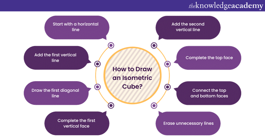
1) Start with a horizontal line: Draw a horizontal line on your paper. This will be the base of the cube.
2) Add the first vertical line: From one end of the horizontal line, draw a vertical line extending upward. The length of this line will be one side of your cube.
3) Draw the first diagonal line: From the top end of the vertical line, draw a diagonal line going down and to the right. The length of this line will be the same as the first vertical line.
4) Complete the first vertical face: Connect the end of the diagonal line to the starting point of the horizontal line, forming the first vertical face of the cube.
5) Add the second vertical line: From the end of the horizontal line opposite the first vertical line, draw a vertical line upward. This line should be parallel to the first vertical line.
6) Complete the top face: Connect the top ends of the two vertical lines with a horizontal line, completing the top face of the cube.
7) Connect the top and bottom faces: Connect the corresponding vertices of the top and bottom faces with diagonal lines, forming the remaining vertical faces of the cube.
8) Erase unnecessary lines: Erase any unnecessary construction lines within the cube. You should be left with a clean isometric representation of a cube.
Ready to master design patterns? Elevate your skills with our Design Patterns Training . Register now for a transformative learning experience!
Isometric Drawing vs one-point perspective
Isometric Drawing and one-point perspective are both methods used in art and technical drawing to represent three-dimensional objects, but they differ in their approach to creating a sense of depth and space.
Isometric Drawing
1) Equal Dimensions: All three axes (length, width, and height) are equally foreshortened. Lines parallel to these axes are drawn at equal angles (typically 30 degrees).
2) Lack of Depth: Isometric Drawings lack the depth and vanishing points associated with perspective drawings. Parallel lines remain parallel and do not converge.
3) Simplicity and Clarity: Isometric Drawings are known for their simplicity and clarity. Objects are represented without distortion along any axis.
4) Common in Technical Drawings: Commonly used in technical drawings, architectural illustrations, and engineering diagrams. Useful for representing objects with accuracy and clarity.
One-point perspective
1) Vanishing Point: Dependent on a single vanishing point on the horizon. Lines converge towards this vanishing point, giving a sense of depth.
2) Foreshortening: Objects closer to the viewer appear larger, and those farther away appear smaller. Vertical lines remain parallel, while horizontal lines converge.
3) Realism and Depth: One-point perspective is often used in realistic and naturalistic art. Creates a more natural sense of depth and space.
4) Common in Fine Art: Widely used in fine art, especially in paintings and drawings, to create realistic scenes. Emphasises the illusion of depth and spatial relationships.
Unleash your creativity with our Logo Design Training ! Elevate your skills and craft impactful logos!
Advantages of Isometric Drawing
Isometric Drawing offers several advantages, particularly in technical and engineering contexts, where accurate and clear representation of three-dimensional objects is essential. Here are some of the advantages of Isometric Drawing:
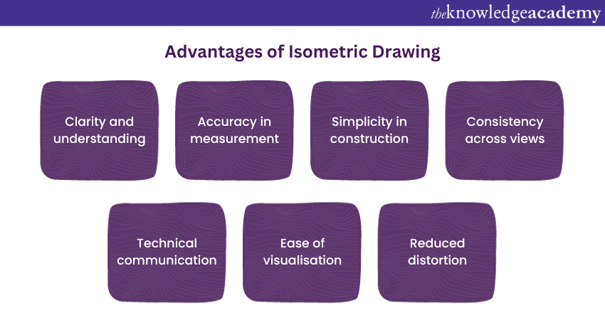
1) Clarity and understanding: Isometric Drawings offer a straightforward and clear representation of three-dimensional objects. This simplicity aids in conveying the spatial relationships between different elements without the complications introduced by perspective drawing.
2) Accuracy in measurement: Isometric Drawings allow for precise measurement of distances and proportions along all three axes. This accuracy is crucial in technical and engineering contexts where precise design specifications are required.
3) Simplicity in construction: Constructing Isometric Drawings is generally simpler compared to more intricate perspective drawings. The method is less mathematically complex, making it more accessible for manual drafting or with the use of basic drafting tools.
4) Consistency across views: Isometric Drawings maintain consistency when representing the same object from different angles. The proportions and relationships between dimensions remain constant, contributing to a standardised representation.
5) Technical communication: Isometric Drawings are a common language in technical and engineering fields. They serve as effective tools for communicating design concepts, plans, and construction details among professionals, facilitating a shared understanding of complex structures.
6) Ease of visualisation: Isometric Drawings provide an accessible means for individuals to visualise how various components fit together in three-dimensional space. This visualisation aids in problem-solving and decision-making during the design and planning stages.
7) Reduced distortion: Unlike some perspective drawings that can introduce distortion, Isometric Drawings aim to maintain a more accurate representation of an object. This lack of distortion is valuable in situations where precise depiction is necessary.
Examples of Isometric Drawing
Isometric Drawings are commonly used in various fields to represent three-dimensional objects. Here are a few examples of Isometric Drawings:
1) Technical illustrations: Isometric Drawings are often used in technical manuals and instructional materials to illustrate the assembly or disassembly of machinery and equipment. These drawings help users understand the structure and function of complex systems.
2) Architectural design: Architects use Isometric Drawings to represent buildings and structures. These drawings provide a clear view of the spatial relationships between different architectural elements, such as rooms, stairs, and other features.
3) Engineering diagrams: Engineers use Isometric Drawings to depict components, mechanisms, and systems. These drawings are valuable for planning and communicating the design of mechanical and structural elements.
4) Product design: Isometric Drawings are commonly employed in product design to showcase the form and function of consumer goods. Designers use them to present a detailed view of products from different angles.
5) Piping and plumbing layouts: I n industrial and construction settings, Isometric Drawings are used to illustrate the layout of pipes and plumbing systems. These drawings help in planning and installation by providing a clear representation of how the components fit together.
Ignite your creativity with Sketchbook Essential Training ! Uncover the secrets to expressive sketching. Join now and bring your ideas to life!
Conclusion
In conclusion, this blog aims to provide a comprehensive understanding of Isometric Drawing—from its historical roots to its practical applications. By exploring its advantages and presenting illustrative examples, readers will gain insight into the importance of Isometric Drawing as a valuable tool in fields ranging from engineering to design.
Join our Animation and Design Training for a journey into the world of dynamic creativity!
Frequently Asked Questions
Upcoming office applications resources batches & dates.
Tue 11th Jun 2024
Tue 13th Aug 2024
Tue 15th Oct 2024
Tue 17th Dec 2024
Get A Quote
WHO WILL BE FUNDING THE COURSE?
My employer
By submitting your details you agree to be contacted in order to respond to your enquiry
- Business Analysis
- Lean Six Sigma Certification
Share this course
Our biggest spring sale.

We cannot process your enquiry without contacting you, please tick to confirm your consent to us for contacting you about your enquiry.
By submitting your details you agree to be contacted in order to respond to your enquiry.
We may not have the course you’re looking for. If you enquire or give us a call on 01344203999 and speak to our training experts, we may still be able to help with your training requirements.
Or select from our popular topics
- ITIL® Certification
- Scrum Certification
- Change Management Certification
- Business Analysis Courses
- Microsoft Azure Certification
- Microsoft Excel Courses
- Microsoft Project
- Explore more courses
Press esc to close
Fill out your contact details below and our training experts will be in touch.
Fill out your contact details below
Thank you for your enquiry!
One of our training experts will be in touch shortly to go over your training requirements.
Back to Course Information
Fill out your contact details below so we can get in touch with you regarding your training requirements.
* WHO WILL BE FUNDING THE COURSE?
Preferred Contact Method
No preference
Back to course information
Fill out your training details below
Fill out your training details below so we have a better idea of what your training requirements are.
HOW MANY DELEGATES NEED TRAINING?
HOW DO YOU WANT THE COURSE DELIVERED?
Online Instructor-led
Online Self-paced
WHEN WOULD YOU LIKE TO TAKE THIS COURSE?
Next 2 - 4 months
WHAT IS YOUR REASON FOR ENQUIRING?
Looking for some information
Looking for a discount
I want to book but have questions
One of our training experts will be in touch shortly to go overy your training requirements.
Your privacy & cookies!
Like many websites we use cookies. We care about your data and experience, so to give you the best possible experience using our site, we store a very limited amount of your data. Continuing to use this site or clicking “Accept & close” means that you agree to our use of cookies. Learn more about our privacy policy and cookie policy cookie policy .
We use cookies that are essential for our site to work. Please visit our cookie policy for more information. To accept all cookies click 'Accept & close'.
Browse Course Material
Course info, instructors.
- Prof. Daniel Frey
- Prof. David Gossard
Departments
- Mechanical Engineering
As Taught In
- Robotics and Control Systems
- Mechanical Design
Learning Resource Types
Design and manufacturing i, design handbook: engineering drawing and sketching.
To see an animated version of this tutorial, please see the Drawing and Drafting section in MIT’s Engineering Design Instructional Computer System. (EDICS)
Drawing Handout Index
Isometric drawing.
Orthographic or Multiview Drawings
Dimensioning
Drawing tools.
Assembly Drawings
Cross-Sectional Views
Half-sections.
Sections of Objects with Holes, Ribs, etc.
More Dimensioning
Where to Put Dimensions
Introduction
One of the best ways to communicate one’s ideas is through some form of picture or drawing. This is especially true for the engineer. The purpose of this guide is to give you the basics of engineering sketching and drawing.
We will treat “sketching” and “drawing” as one. “Sketching” generally means freehand drawing. “Drawing” usually means using drawing instruments, from compasses to computers to bring precision to the drawings.
This is just an introduction. Don’t worry about understanding every detail right now - just get a general feel for the language of graphics.
We hope you like the object in Figure 1, because you’ll be seeing a lot of it. Before we get started on any technical drawings, let’s get a good look at this strange block from several angles.
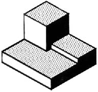
Figure 1 - A Machined Block.
The representation of the object in figure 2 is called an isometric drawing. This is one of a family of three-dimensional views called pictorial drawings. In an isometric drawing, the object’s vertical lines are drawn vertically, and the horizontal lines in the width and depth planes are shown at 30 degrees to the horizontal. When drawn under these guidelines, the lines parallel to these three axes are at their true (scale) lengths. Lines that are not parallel to these axes will not be of their true length.
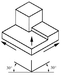
Figure 2 - An Isometric Drawing.
Any engineering drawing should show everything: a complete understanding of the object should be possible from the drawing. If the isometric drawing can show all details and all dimensions on one drawing, it is ideal. One can pack a great deal of information into an isometric drawing. However, if the object in figure 2 had a hole on the back side, it would not be visible using a single isometric drawing. In order to get a more complete view of the object, an orthographic projection may be used.

Orthographic or Multiview Drawing
Imagine that you have an object suspended by transparent threads inside a glass box, as in figure 3.
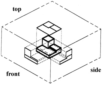
Figure 3 - The block suspended in a glass box.
Then draw the object on each of three faces as seen from that direction. Unfold the box (figure 4) and you have the three views. We call this an “orthographic” or “multiview” drawing.
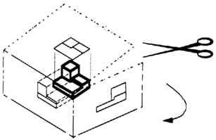
Figure 4 - The creation of an orthographic multiview drawing.
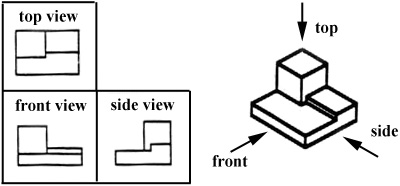
Figure 5 - A multiview drawing and its explanation.
Which views should one choose for a multiview drawing? The views that reveal every detail about the object. Three views are not always necessary; we need only as many views as are required to describe the object fully. For example, some objects need only two views, while others need four. The circular object in figure 6 requires only two views.
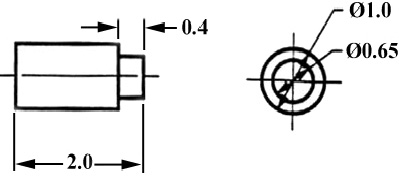
Figure 6 - An object needing only two orthogonal views.
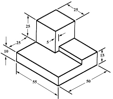
Figure 7 - An isometric view with dimensions.
We have “dimensioned” the object in the isometric drawing in figure 7. As a general guideline to dimensioning, try to think that you would make an object and dimension it in the most useful way. Put in exactly as many dimensions as are necessary for the craftsperson to make it -no more, no less. Do not put in redundant dimensions. Not only will these clutter the drawing, but if “tolerances” or accuracy levels have been included, the redundant dimensions often lead to conflicts when the tolerance allowances can be added in different ways.
Repeatedly measuring from one point to another will lead to inaccuracies. It is often better to measure from one end to various points. This gives the dimensions a reference standard. It is helpful to choose the placement of the dimension in the order in which a machinist would create the part. This convention may take some experience.
There are many times when the interior details of an object cannot be seen from the outside (figure 8).
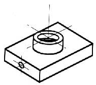
Figure 8 - An isometric drawing that does not show all details.
We can get around this by pretending to cut the object on a plane and showing the “sectional view”. The sectional view is applicable to objects like engine blocks, where the interior details are intricate and would be very difficult to understand through the use of “hidden” lines (hidden lines are, by convention, dotted) on an orthographic or isometric drawing.
Imagine slicing the object in the middle (figure 9):
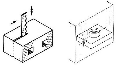
Figure 9 - “Sectioning” an object.
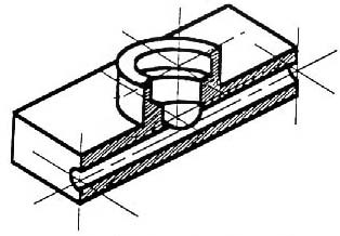
Figure 10 - Sectioning the object in figure 8.
Take away the front half (figure 10) and what you have is a full section view (figure 11).
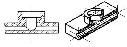
Figure 11 - Sectioned isometric and orthogonal views.
The cross-section looks like figure 11 when it is viewed from straight ahead.
To prepare a drawing, one can use manual drafting instruments (figure 12) or computer-aided drafting or design, or CAD. The basic drawing standards and conventions are the same regardless of what design tool you use to make the drawings. In learning drafting, we will approach it from the perspective of manual drafting. If the drawing is made without either instruments or CAD, it is called a freehand sketch.

Figure 12 - Drawing Tools.
"Assembly" Drawings
An isometric view of an “assembled” pillow-block bearing system is shown in figure 13. It corresponds closely to what you actually see when viewing the object from a particular angle. We cannot tell what the inside of the part looks like from this view.
We can also show isometric views of the pillow-block being taken apart or “disassembled” (figure 14). This allows you to see the inner components of the bearing system. Isometric drawings can show overall arrangement clearly, but not the details and the dimensions.
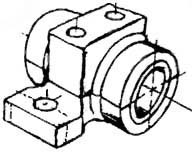
Figure 13 - Pillow-block (Freehand sketch).
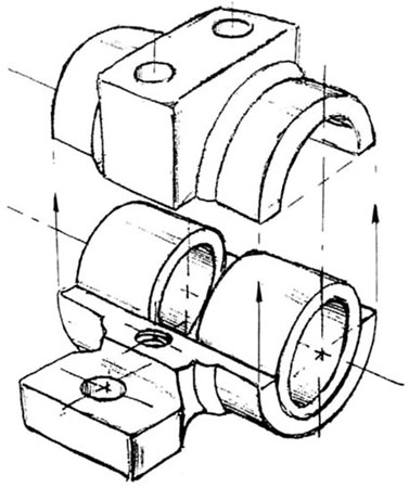
Figure 14 - Disassembled Pillow-block.
A cross-sectional view portrays a cut-away portion of the object and is another way to show hidden components in a device.
Imagine a plane that cuts vertically through the center of the pillow block as shown in figure 15. Then imagine removing the material from the front of this plane, as shown in figure 16.
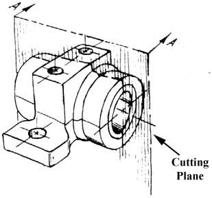
Figure 15 - Pillow Block.
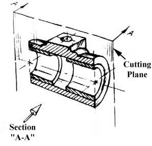
Figure 16 - Pillow Block.
This is how the remaining rear section would look. Diagonal lines (cross-hatches) show regions where materials have been cut by the cutting plane.
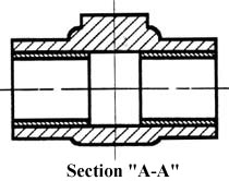
Figure 17 - Section “A-A”.
This cross-sectional view (section A-A, figure 17), one that is orthogonal to the viewing direction, shows the relationships of lengths and diameters better. These drawings are easier to make than isometric drawings. Seasoned engineers can interpret orthogonal drawings without needing an isometric drawing, but this takes a bit of practice.
The top “outside” view of the bearing is shown in figure 18. It is an orthogonal (perpendicular) projection. Notice the direction of the arrows for the “A-A” cutting plane.
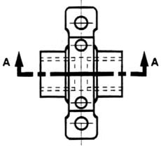
Figure 18 - The top “outside” view of the bearing.
A half-section is a view of an object showing one-half of the view in section, as in figure 19 and 20.
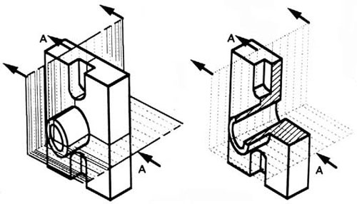
Figure 19 - Full and sectioned isometric views.
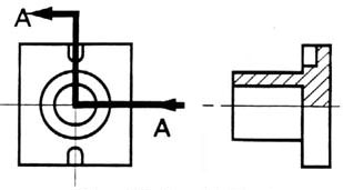
Figure 20 - Front view and half section.
The diagonal lines on the section drawing are used to indicate the area that has been theoretically cut. These lines are called section lining or cross-hatching . The lines are thin and are usually drawn at a 45-degree angle to the major outline of the object. The spacing between lines should be uniform.
A second, rarer, use of cross-hatching is to indicate the material of the object. One form of cross-hatching may be used for cast iron, another for bronze, and so forth. More usually, the type of material is indicated elsewhere on the drawing, making the use of different types of cross-hatching unnecessary.
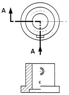
Figure 21 - Half section without hidden lines.
Usually hidden (dotted) lines are not used on the cross-section unless they are needed for dimensioning purposes. Also, some hidden lines on the non-sectioned part of the drawings are not needed (figure 12) since they become redundant information and may clutter the drawing.
Sectioning Objects with Holes, Ribs, Etc.
The cross-section on the right of figure 22 is technically correct. However, the convention in a drawing is to show the view on the left as the preferred method for sectioning this type of object.
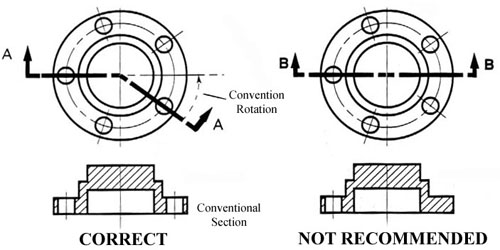
Figure 22 - Cross section.
The purpose of dimensioning is to provide a clear and complete description of an object. A complete set of dimensions will permit only one interpretation needed to construct the part. Dimensioning should follow these guidelines.
- Accuracy: correct values must be given.
- Clearness: dimensions must be placed in appropriate positions.
- Completeness: nothing must be left out, and nothing duplicated.
- Readability: the appropriate line quality must be used for legibility.
The Basics: Definitions and Dimensions
The dimension line is a thin line, broken in the middle to allow the placement of the dimension value, with arrowheads at each end (figure 23).
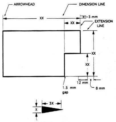
Figure 23 - Dimensioned Drawing.
An arrowhead is approximately 3 mm long and 1 mm wide. That is, the length is roughly three times the width. An extension line extends a line on the object to the dimension line. The first dimension line should be approximately 12 mm (0.6 in) from the object. Extension lines begin 1.5 mm from the object and extend 3 mm from the last dimension line.
A leader is a thin line used to connect a dimension with a particular area (figure 24).
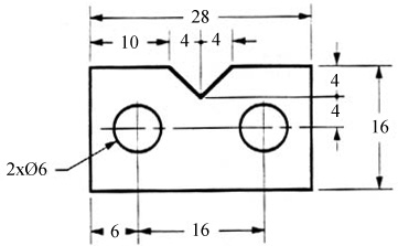
Figure 24 - Example drawing with a leader.
A leader may also be used to indicate a note or comment about a specific area. When there is limited space, a heavy black dot may be substituted for the arrows, as in figure 23. Also in this drawing, two holes are identical, allowing the “2x” notation to be used and the dimension to point to only one of the circles.
Where To Put Dimensions
The dimensions should be placed on the face that describes the feature most clearly. Examples of appropriate and inappropriate placing of dimensions are shown in figure 25.
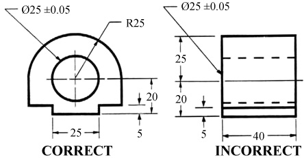
Figure 25 - Example of appropriate and inappropriate dimensioning.
In order to get the feel of what dimensioning is all about, we can start with a simple rectangular block. With this simple object, only three dimensions are needed to describe it completely (figure 26). There is little choice on where to put its dimensions.
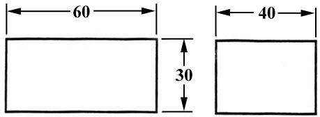
Figure 26 - Simple Object.
We have to make some choices when we dimension a block with a notch or cutout (figure 27). It is usually best to dimension from a common line or surface. This can be called the datum line of surface. This eliminates the addition of measurement or machining inaccuracies that would come from “chain” or “series” dimensioning. Notice how the dimensions originate on the datum surfaces. We chose one datum surface in figure 27, and another in figure 28. As long as we are consistent, it makes no difference. (We are just showing the top view).
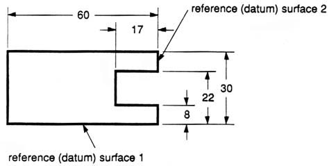
Figure 27 - Surface datum example.
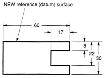
Figure 28 - Surface datum example.
In figure 29 we have shown a hole that we have chosen to dimension on the left side of the object. The Ø stands for “diameter”.
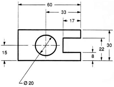
Figure 29 - Exampled of a dimensioned hole.
When the left side of the block is “radiuses” as in figure 30, we break our rule that we should not duplicate dimensions. The total length is known because the radius of the curve on the left side is given. Then, for clarity, we add the overall length of 60 and we note that it is a reference (REF) dimension. This means that it is not really required.
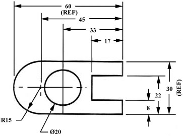
Figure 30 - Example of a directly dimensioned hole.
Somewhere on the paper, usually the bottom, there should be placed information on what measuring system is being used (e.g. inches and millimeters) and also the scale of the drawing.
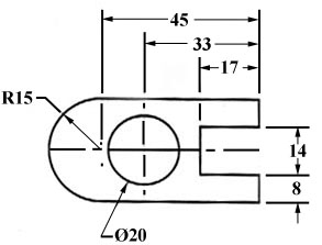
Figure 31 - Example of a directly dimensioned hole.
This drawing is symmetric about the horizontal centerline. Centerlines (chain-dotted) are used for symmetric objects, and also for the center of circles and holes. We can dimension directly to the centerline, as in figure 31. In some cases this method can be clearer than just dimensioning between surfaces.

You are leaving MIT OpenCourseWare
- Mastering Isometric Projection: 5 Common Drawing Techniques for Your Assignments
5 Techniques for Stunning Isometric Projection Assignment Drawings

Isometric projection is an effective drawing technique for representing three-dimensional objects on a two-dimensional surface. It depicts the shape, size, and dimensions of an object clearly and exactly. Understanding and implementing isometric projection will substantially improve your technical drawing skills, whether you're a student working on an assignment or a professional designer. This blog from Architecture Assignment Help will go over five typical isometric projection sketching approaches that you can use in your isometric assignments .
Isometric Grid Method:
An essential approach for creating isometric drawings is the isometric grid method. It entails drawing an equilateral triangle grid on your paper to represent the three axes of an isometric projection. Each grid point corresponds to a certain coordinate in the three-dimensional space of the object. You may precisely sketch the item in isometric projection by connecting these points. This method is very beneficial for novices because it provides a systematic approach to making isometric drawings.

Box method:
Another popular technique for making isometric projections is the box method. Visualizing the thing as a series of interlocking boxes is required. Begin by creating a rectangle box to represent the object's base or front face. Then, extend lines at a 30-degree angle from each corner of the box to form the object's sides. Complete the isometric projection by connecting the matching corners. By breaking complex structures down into simpler geometric forms, the box approach simplifies them.
Offset Technique:
The offset method is a versatile technique for drawing objects that are not parallel to the isometric axis. It entails sketching the object in a slightly rotated position with one of the three basic axes highlighted. To utilize this method, first, identify the object's orientation relative to the isometric axes. The item should then be drawn with small offsets from the isometric grid lines. When designing things with oblique angles or unusual shapes, the offset approach comes in handy.
Complexity to Isometric Drawings Using the Offset Method
The offset method in isometric projection is a versatile approach that allows you to create objects that are not aligned with the usual isometric axes. It allows you to portray objects from various angles or orientations, giving your isometric drawings depth and intricacy. You can make isometric projections of objects with oblique angles, unusual forms, or non-standard orientations using the offset approach. Let's look at the essential features and advantages of the offset method in isometric projection.
Understanding Object Orientation:
In isometric projection, objects are normally aligned at 120-degree angles with the three principal axes (x, y, and z). The offset approach, on the other hand, permits you to stray from this usual alignment. It necessitates a thorough understanding of object orientation and its relationship to the isometric axes. The offset method can be used to precisely describe an item by displaying its location and rotation relative to the isometric axes.
Drawing with Slight Offsets:
To begin, determine the orientation of the item you wish to draw about the isometric axes. After you've determined the position of the object, draw the isometric projection with small offsets from the isometric grid lines. These offsets represent the divergence of the object from the standard alignment. You can generate an isometric projection that precisely portrays the object's orientation by connecting the matching points and lines.
Depicting Oblique Angles and Irregular Shapes:
When sketching objects with oblique angles or irregular shapes that do not fit cleanly with the isometric axis, the offset approach comes in handy. For example, if you want to draw a cube with an angle or a polygon with sides at non-orthogonal angles, you can use the offset approach to precisely represent these orientations. You may find the proper offsets and make a believable isometric projection by carefully observing the object's angles and proportions.
Adding Depth and Complexity:
The offset approach adds depth and complexity to your isometric drawings by creating perspective changes. The offset method allows you to introduce alternative viewpoints and orientations rather than depending simply on the traditional 120-degree angles. This results in a more dynamic portrayal of the item, which improves the visual intrigue and realism of your isometric drawings. Using the offset method, objects appear more three-dimensional and visually appealing.
Increasing Visual Appeal:
Using the offset method, you may break free from the stiffness of typical isometric projections, giving your designs a unique and creative touch. You may make isometric drawings that stand out and attract attention by varying the orientation and perspective. The offset method fosters experimentation and creativity, allowing you to experiment with multiple perspectives and create visually interesting compositions for your isometric drawings.
Experimentation and Practice:
Mastering the offset approach in isometric projection necessitates practice and experimentation. To become acquainted with the approach, begin by drawing small things with slight offsets from the isometric grid lines. As your confidence grows, try drawing more complicated things with varied angles and orientations. Examine how offsets affect the overall look and depth of your isometric drawings. You will improve your skills and have a solid understanding of object orientation in isometric projection as you practice.
Method of freehand drawing:
While the grid and box methods are both exact and structured ways of isometric drawing, the freehand method is more artistic and expressive. This method entails sketching isometric projections without using grids or boxes. Instead, you rely on your ability to appropriately visualize and represent the item. Freehand sketching takes practice and a good understanding of perspective, but it allows for more creativity and freedom in your work.
Let's look at the essential features and advantages of the freehand method in isometric projection.
Three-Dimensional Visualization:
The freehand method requires you to see items in three dimensions without the use of guidelines or frameworks. It necessitates a firm grasp of perspective and spatial relationships. With practice, you will be able to mentally rotate and move things, allowing you to depict them precisely in isometric projection. The freehand method improves not only your technical drawing skills but also your spatial awareness and visual perception.
Expressive Interpretation:
In contrast to the organized grid or box systems, the freehand method allows for more interpretation and personal style. It enables you to add creative flair to your isometric drawings. You can draw attention to specific aspects, exaggerate proportions, or experiment with various line weights and styles. Because of this creative freedom, you may use your isometric drawings to portray a specific mood, ambiance, or narrative, making them genuinely distinctive and intriguing.
Developing Observation Skills:
The freehand method requires you to attentively observe and comprehend the topic matter. You must research the object's shapes, angles, and dimensions, as well as how light interacts with it. You may accurately represent these elements in your isometric drawings by carefully observing and evaluating them. This exercise improves your observational abilities and attention to detail, which you can then apply to other parts of art and design.
Spontaneity and fluidity:
The freehand style promotes a more spontaneous and intuitive approach to drawing. You may make isometric drawings with a sense of flow and movement depending on your intuition and aesthetic senses. This method enables fast, expressive strokes that capture the spirit of the thing. The freehand method's fluidity and spontaneity can result in lively and energetic isometric drawings with their charm and personality.
Emphasizing creative Interpretation:
In freehand isometric drawings, the emphasis switches from technical precision to creative interpretation. While precision is still required, the goal is to capture the spirit and character of the thing rather than to achieve mathematical exactness. This artistic interpretation allows you to express your unique viewpoint and point of view, changing your isometric drawings into a form of creative expression.
Practicing and Improving Skills:
Mastering the freehand method in isometric projection necessitates regular practice and experimentation. Begin by drawing simple objects and work your way up to more complex subjects. Take note of proportions, angles, and perspective. Experiment with various approaches, line weights, and shading patterns to establish your distinct style. The more you practice, the more comfortable you will be sketching freehand isometric figures.
The isometric projection freehand method allows a world of artistic freedom and creativity. You may make isometric drawings that are not only technically precise but also infused with your distinct artistic touch depending on your visualization skills, observation, and personal flair. Accept the openness and spontaneity of the freehand method and utilize it to explore new ideas and push the limits of your creativity. You will build a distinct style and produce intriguing isometric drawings that stand out from the crowd with effort and practice.
Rendering and shading:
Once you've mastered the fundamentals of isometric projection, you can improve your drawings by using shading and rendering techniques. Shading your isometric drawings helps to create the illusion of depth and volume. To represent the direction and intensity of light on the object's surfaces, use techniques like hatching, cross-hatching, or stippling. Rendering techniques like adding textures and gradients improve the realism of your isometric designs.
Techniques for Shading: Shading is an important part of generating realistic isometric drawings. It entails applying ways to convey the direction and intensity of light on the object's surfaces, providing a sense of depth and volume. Here are three commonly used shading techniques:
Hatching is the process of drawing parallel lines or strokes in a specified direction to represent areas of shadow or darkness on the surface of an item. You can change the strength and gradient of the shadows by varying the spacing and thickness of the lines. Hatching works well on flat surfaces or regions with a uniform texture.
Cross-Hatching:
Cross-hatching extends the concept of hatching by adding a second set of parallel lines that intersect the first set of hatch lines. You may build more complicated shading patterns and textures by adjusting the angle and density of the intersecting lines. Cross-hatching works well for illustrating curved surfaces or areas with intersecting planes.
Stippling is the process of generating shading using a sequence of little dots or stippled patterns. You may achieve different tones and textures by adjusting the density and size of the dots. Stippling is useful for expressing rough or textured surfaces and can give your isometric drawings a distinct aesthetic appeal.
Techniques for Rendering:
Rendering techniques enhance the appearance, texture, and realism of your isometric designs by complementing shading. Here are two common rendering strategies you might try:
Textures may bring your isometric drawings to life and offer a more immersive experience. By carefully observing and copying the patterns and qualities of various textures, such as wood, metal, fabric, or stone, you can create your own. Textures can be created using precise hatching, cross-hatching, or stippling techniques, as well as by combining different line weights and patterns.
Gradients are used to create a progressive change in value over a surface by gently transitioning from one hue or tone to another. Gradients are particularly useful for things with curved or rounded surfaces because they allow you to imitate the dance of light and shadow. To accomplish seamless transitions between tones, use blending techniques such as blending stumps, brushes, or even digital tools.
Experimentation and application:
To perfect shading and rendering techniques, practice and experiments are required. Begin by investigating real-world objects and watching how light interacts with various surfaces and materials. Take note of the light's direction, intensity, and quality, as well as the way shadows are cast. This insight will help you make better shading decisions and create more realistic isometric graphics.
It is also necessary to experiment with various tools and materials. To apply shading and rendering techniques, you can use pencils, pens, markers, or digital tools, depending on your inclination. Each medium has its own set of possibilities and effects, so experiment with several mediums to see what works best for you.
The use of shading and rendering techniques is critical for increasing the realism and visual impact of your isometric designs. You may bring life and interest to your drawings by mastering hatching, cross-hatching, stippling, and applying textures and gradients. To improve your talents, remember to practice, examine real-life items, and experiment with new tools and materials. You may take your isometric drawings to new levels of aesthetic expression with effort and imagination.
Conclusion:
Isometric projection is a useful ability for everyone who works in technical drawing or design. You can make accurate and visually appealing isometric drawings for your assignments by knowing and applying the five typical strategies covered in this article. Whether you prefer the rigidity of grid and box approaches or the artistic freedom of freehand, practice and experimenting will help you improve your skills. So, take out your pencils and begin exploring the world of isometric projection - the possibilities are limitless!
Post a comment...
Mastering isometric projection: 5 common drawing techniques for your assignments submit your assignment, attached files.

Piping Design Basics- Piping Isometric Drawings | Piping Isometrics
What is piping isometric drawing.
Once the three-dimensional (3D) model has been established in piping design software like PDS, PDMS, or SP3D, Piping Designers /Engineers need to convey that information to the yard for fabrication and the site for Construction. The transferred information must be sufficient for the fabricator with the vision of what is to be fabricated and how the piping should be connected with other elements, with exact dimensions and a complete build/Bill of materials ( BOM ). This is where Piping Isometric Drawings play a magnificent role. So piping isometrics are directly used for the following situations:
- For Construction Services
- For marking up deviation during site modifications/ as-builting .
- For reference as Stress Analysis model built up and the final stress markup for updating stress requirements.
Piping isometrics indirectly helps to calculate many parameters required during project execution like:
- Inch Meter can be estimated as the Length of pipe (in meters) x Size of pipe ( in inches)
- Inch Dia is calculated as the Size of the Pipe joint ( in inch) x No, of Joints
- Pipe Weight is calculated as π x diameter of the pipe (in m) x length (in m) x thickness (in mm) x density of pipe material. Density of CS = 7.85 g/cm3
- The volume of Water required for hydro testing is estimated as π x {Pipe ID (in meter)}² x Length of Pipe
- Insulation Area (in m²) can be found as [π(Pipe OD+ insulation thickness)] (all in meter) x Length of Pipe (in meter)
By definition, Isometric drawings are a pictorial representation that combines height-width-depth/length into a single view with 30 degrees from its horizontal plane as shown in the attached image.

Features of Piping Isometric Drawing
An isometric Drawing is a two-dimensional (2D) drawing that represents the 3D piping system . The important features are
- It is not drawn to the scale, but it is proportionate with the exact dimensions represented.
- Pipes are drawn with a single line irrespective of the line sizes, as well as the other configurations such as reducers , flanges , and valves .
- Pipes are shown in the same size. The actual sizes are notified in the Bill of Material, tagging, call-out, or notes.
- Pipe Line Number
- Continuation isometric number
- Flow direction
- Piping dimensions
- Piping joint types , weld types
- Flange and valve types
- Equipment connection details
- Piping and Component descriptions with size, quantity, and material codes
Piping Isometric drawings are popular because of their simplicity, yet efficient in conveying complex information. The following figure gives an example of how one Isometric drawing can represent three orthographic drawings. That is just a simple piping drawing . Imagine complex design and yet orthographic drawings are used for construction, that is really a headache.

In earlier days, Isometric drawings were hand-drawn. With the innovation and advancement of the digital age, isometrics are drawn by AutoCAD/Microstation software. In recent days, 3D models could automatically extract the Isometric with a single click of a mouse.
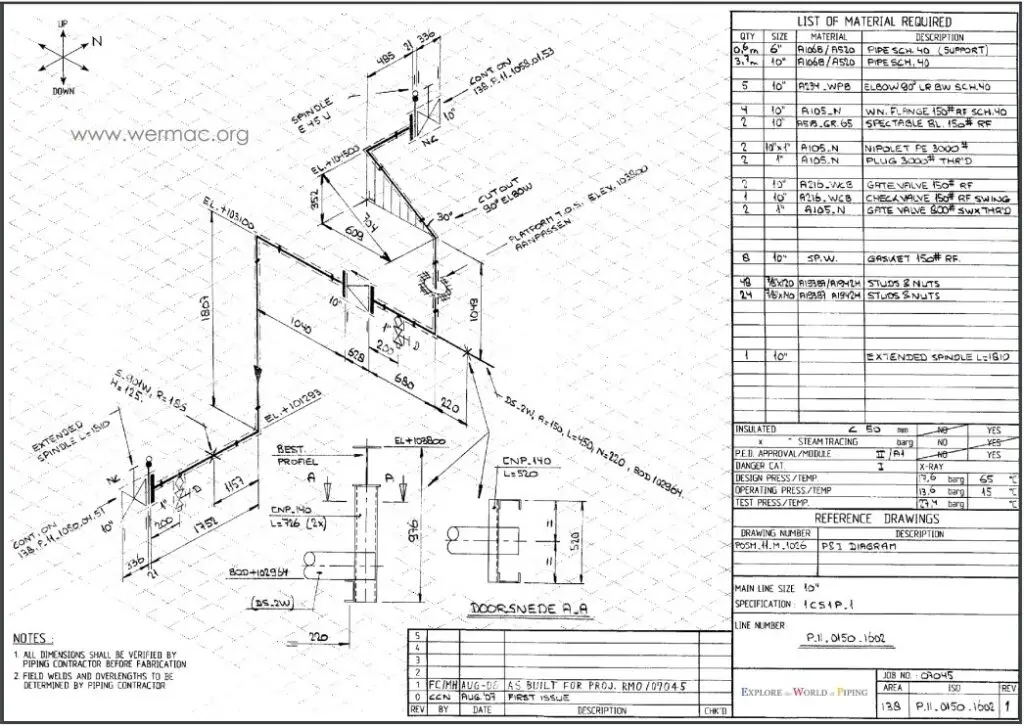
How to Read Piping Isometric Drawings?
1. First, imagine that the piping system is built in a box . This basic imagination is required for the piping to have an offset. So, it will help you to imagine, how the piping configuration will look as it travels.

2. Offset happens when the pipe turns to any angle other than 90 degrees or to accommodate the odd nozzle’s location or tie-in point connections. A popular use is a 45-degree elbow and this is used extensively in piping design. In such cases, piping design may land on Northeast, Southeast, Northwest, or Southwest axes. In order to check the dimension of pipe length with offset, common Pythagoras’s theorem and Trigonometric rule can be used. A sample calculation is shown below as a reference-
Example of length calculation in Piping Isometric

Example of offset

If you happen to have difficulties reading the offset, try to draw the imaginary box. It could help you have a better understanding of which axes the pipe travels and how the piping should look like. In the example given, take the flow from ‘x’, the pipe goes up; then up-northwest; then north. As you get along with Iso a lot, things will come naturally.
3. A North arrow is provided in all piping isometrics to inform the location of the piping system in the piping/ general arrangement drawing.
4. The piping isometrics also has coordinates & elevation detailed information to verify the exact length of the pipe in horizontal and vertical axes respectively. The dimensions in Isometric drawings are measured from the pipe centreline and not from the outer diameter of the pipe (refer to the image attached below for reference).

With the advancement of technology, there could be minimum or even zero possibilities that the North arrow, coordinates, and elevation in Isometric would differ from the piping arrangement; hence the dimensions and MTO should match exactly if the source 3D model is the same.
However, It is always better to check and verify as there could be some issues with the modeling itself that may cause discrepancies in material and quantity. For example, if double piping is modeled by mistake, it will read the double quantity of material.
5. Isometric drawings also inform which piping should be constructed at the fabrication shop and which should be assembled at the construction/platform field itself. The complete piping system is separated into pieces that are transported to the site for erection. These small pipe pieces are termed piping spools . One sheet of Isometric drawing normally has few spools.
Every weld that is assembled between spools at the construction site is termed a field weld (FW) . There is one more type of weld that is known as field-fit weld (FFW). This FFW is defined by the designer if he/she could foresee that the spool might require some adjustment before the final fit-up, so at the location of FFW that has been marked, it will be given some pipe length tolerance (commonly 150-300mm). Usually, FFW will occur at the nozzle of equipment or tie-in locations.

The whole assembled piping will look like the following after it is assembled at the field.

Piping isometric drawing symbols
For reading and understanding a piping isometric drawing, one should learn the piping isometric drawing symbols thoroughly. Usually, all these piping and pipeline drawing symbols are constant and do not vary much from one organization to another. Knowing the piping drawing symbols will provide various information like:
- Type of Piping Joint: Piping and pipeline drawing symbols throw lights on the type of joint like Buttweld, socket weld , or Threaded .
- Type of Piping Components: Isometric drawing piping symbols serve as a ready reference for the type of fittings and components.
- Instrument items: Knowing the piping isometric symbols will help in recognizing the instrument and special piping items in the isometric.
- Equipment Connection: Equipment connected to a piping system is also understood with piping symbols.
- Knowing piping symbols for isometric drawing is useful in preparing MTO/BOM.
Commonly used piping isometric drawing symbols are shown below for reference purposes
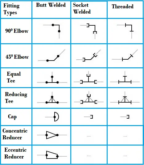
Piping Isometric Drawing Software
Piping isometric drawing software is an essential tool for piping engineers and designers to create detailed isometric drawings of piping systems. These tools generate the 3D representation of the piping layout, including pipe dimensions, fittings, valves, and other components. There are many piping isometric drawing software programs available in the market which makes the task of a piping designer very easy. The piping isometric drawing software packages are two types; 2D software and 3D software. In 2D software, the piping isometric is generated manually whereas 3D piping isometric software programs have the capability of automatic isometric generation.
Top Piping Isometric Drawing Software Tools
Choosing the right piping isometric drawing software tool may be difficult as there are various options available. However, most design consultancies choose the complete software program considering the complexity of the job, costs, and client requirements. Here are some popular piping isometric drawing software tools:
AutoDesk Plant 3D: AutoDesk Plant 3D is an industry-standard software for piping design and isometric drawing. It offers specialized tools for creating and editing piping layouts, generating isometric drawings, and managing pipe specifications.
CADWorx: CADWorx, developed by Hexagon PPM, is a 3D plant design and modeling software that integrates with AutoCAD to provide piping engineers with tools for generating isometric drawings, equipment modeling, and structural design.
AVEVA E3D (Everything3D): AVEVA E3D is a next-generation 3D design and modeling software that supports detailed piping design and the creation of isometric drawings. It offers advanced capabilities for multidisciplinary plant design.
AVEVA PDMS (Plant Design Management System): AVEVA PDMS is a powerful 3D modeling and design software widely used in the process industry. It allows for the creation of isometric drawings, as well as detailed 3D modeling of piping and equipment.
SmartPlant 3D (SP3D): SmartPlant 3D (SP3D) is another powerful 3D plant design and modeling software offered by Intergraph (Hexagon PPM). It supports the creation of detailed piping layouts and isometric drawings, often used for large-scale projects.
SmartPlant Isometrics: Part of the SmartPlant suite by Intergraph (now Hexagon PPM), SmartPlant Isometrics is designed for creating isometric drawings, providing automated tools for generating accurate and standardized piping isometrics.
SolidWorks Piping: SolidWorks, a popular 3D CAD software, includes a Piping add-on module that allows users to create detailed piping designs and generate isometric drawings directly within the SolidWorks environment.
Pipe-Flo Professional: Pipe-Flo Professional is a piping system design and analysis software that includes features for generating isometric drawings, as well as assessing the hydraulic performance of piping systems.
AutoCAD MEP: AutoCAD MEP is a specialized version of AutoCAD designed for mechanical, electrical, and plumbing (MEP) systems. It includes tools for creating isometric drawings of piping systems.
MicroStation: MicroStation is a CAD software platform developed by Bentley Systems. It can be used for piping design and the creation of isometric drawings, especially when integrated with Bentley’s other plant design software solutions.
PDS (Plant Design System) by Intergraph (Hexagon PPM): PDS is a comprehensive plant design and modeling software suite that includes tools for creating isometric drawings, 3D modeling, and engineering analysis for piping and equipment.
Bentley AutoPIPE: Bentley AutoPIPE is a comprehensive software solution for piping analysis and design. It includes features for creating isometric drawings, analyzing stress and load conditions, and ensuring compliance with industry standards.
CAESAR II: While CAESAR II is primarily a pipe stress analysis software, it can generate isometric drawings as part of its output. It is commonly used for verifying the structural integrity of piping systems.
Online Video Courses on Piping Isometrics
If you wish to explore more about piping isometrics, you can opt for the following online video course
- Piping Design Engineering and Piping Isometrics Masterclass
- Piping Isometrics Demystified
- Piping Fabrication with Isometrics
Video Tutorial of Basics of Piping Isometric Drawing
The following video tutorial on the basics of piping isometric drawing will clarify some of your doubts.
Some more Resources for you… Salient Points to check while reviewing Piping Isometric Drawings Preparation of Piping Isometrics Types of Piping Drawings
- Credit to other sources: svlele.com, wermac.org, pipingengineer.org, thepiping.com, spedweb.com, enggcyclopedia.com, rishabheng.com
Related Posts:
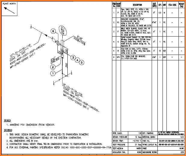
Nur Hidayah Haron
A Passionate Piping Engineer having extensive experience in the oil and gas field; mainly for topside piping system, subsea manifold and onshore LNG facilities. Familiar with codes and standards, i.e. American Petroleum Institute (API) standards, Petronas Technical Specification (PTS), Shell’s Design Engineering Practices (DEP), American Society of Mechanical Engineer (ASME), and American Society for Testing and Materials (ASTM), etc. To know more follow her on https://www.linkedin.com/in/nur-hidayah-haron-04881737/
21 thoughts on “ Piping Design Basics- Piping Isometric Drawings | Piping Isometrics ”
Hi, I would like to familiar with isometric Piping. My basic is Diploma in Mechanical Engineering and my experience is MEPmechanical side. Like PHE and Fire Fighting only 2D with arch Background. Max Pipe size i handled 12″in Fire fighting. I would like to learn more in Piping Isometrics
Hi Ramesh, Thank you for your comment. As a start, you may take any P&ID and compare it to the respective Isometric drawings. Start from one point till the end. I believe, over time you will master it.
Hi, I have a Electrical Designer background and the job I have now would like me to do Piping ISO’s. I do not know where to start at I have been looking at the pipe they want to install on the Area and I’m having all kinds of trouble. So if you can help I would appreciate it. Where do I need to start at?
Excellent info about piping
I would like too share knowledge about piping scope. I have done Bachelor’s degree of Mechanical engineering also completed Piping design (PDMS) software as per ASME. Good knowledge of piping, isometric, P&id, layout, BOQ & BOm. Good knowledge of Code & Std. Good knowledge of Pipe/Wall thickness calculation. I have 3 years experience in oil & gas field For more query/ information please feel free to contact me.
Good morning bro
how do I contact u..please if u can add me on what’s app I shall b grateful.08066081642
Good Evening Mohammad,
My name is Michael, I’m an apprentice steamfitter, and I want to become a journeyman detailer. I am trying to wrap my mind around two drawings and would greatly appreciate your help if you could email me at [email protected] I would really appreciate any help and guidance you could provide. Thank you and have a great day/night.
Very nice .Knowledge stetus.
do you have examples of house plans in PDF
Hi, i’m kris with mechanical engineer background. And i’m as employee at one of foreign company in Indonesia. I would to asking you about piping symbols for uPVC or HDPE material. Is that equal with socket welded symbol for steel pipe material ?
piep line kase napa jata hai uska formula bataeye
Any samples of combined/mixed piping matl iso, i.e., s/s & pvc piping? Tnx.
Hi, I am a piping engineer, with more than 6 years of site experience. I want to shift from site to design, which was my primary interest. Can you guys please suggest / advice, what should I do to get it into design?
Excellent tutorial. Thanks
Thank you for this very useful article Ma’am.
Its very useful info.
Hi, can you plz share the formula-how to calculate the total weight using Pipe dia, schedule and length of the pipe.. for example: pipe dia 12″, SCH 40s, lengh 4m
E3D is the aveva software for used to model piping. It is used in oil and gas industries. We can extract isometrics.
Dear sir Sabse hard isometic droing ka tampalet banane ka koe Aasan tarika bataye
Thanks for sharing.
Leave a Reply Cancel reply
Your email address will not be published. Required fields are marked *
Save my name and email in this browser for the next time I comment.
Recent Posts
Welding Repair: Techniques, Procedures, and Standards
Welding repair is one of the frequently used hot working methods in process industries. For industries relying on heavy equipment such as pressure vessels, the welding repair method is indispensable...
Teflon vs PTFE: Major Differences | Applications of PTFE in the Piping Industry
It is really difficult sometimes to find out "what actually means what". PTFE vs Teflon is such an example. Our universe is full of technical jargon, acronyms, and trade names. So, to find out the...


IMAGES
VIDEO
COMMENTS
Drawing Isometric Views from Coded Plans. As an optional/extra credit assignment, present to students the following peer teach exercise: Still in pairs, show students the drawing tips on slide 9. Then show students the coded plan shown to the far left on slide 10 (same as Figure 6-far left. Ask them to draw two different isometric views of the ...
For better images of the practice, download from the links below:Orthographic views (please don't make changes on my drive):Example 1: https://drive.google.c...
An isometric drawing is a 3D representation of an object, room, building or design on a 2D surface. One of the defining characteristics of an isometric drawing, compared to other types of 3D representation, is that the final image is not distorted and is always to scale. This is due to the fact that the foreshortening of the axes is equal.
Isometric drawing is a fun and creative way to introduce geometry and spatial thinking to your class. This technique allows students to draw 3D objects on a two-dimensional surface, promoting problem-solving skills and visualization. We have gathered a variety of isometric drawing activities that …
All Lesson Plans Isometric Drawings: Part II Overview and Objective. In Isometric Drawings: Part 1, students will construct the side views of the three-dimensional objects and then, they will construct the 3D objects whose side views are given.. Before starting this activity, you may want to check the Isometric Drawings Part I Task.. Warm-Up
Isometric Drawing Tool. Grade: 3rd to 5th, 6th to 8th, High School. Use this interactive tool to create dynamic drawings on isometric dot paper. Draw figures using edges, faces, or cubes. You can shift, rotate, color, decompose, and view in 2‑D or 3‑D. Start by clicking on the cube along the left side; then, place cubes on the grid where ...
Isometric Drawing is a powerful method in the realm of technical and artistic representation, offering a clear and precise way to portray three-dimensional objects on a two-dimensional surface. This blog explores What is an Isometric Drawing, delving into its history, the practical process of drawing an isometric cube, and a comparative ...
Isometric Drawing. The representation of the object in figure 2 is called an isometric drawing. This is one of a family of three-dimensional views called pictorial drawings. In an isometric drawing, the object's vertical lines are drawn vertically, and the horizontal lines in the width and depth planes are shown at 30 degrees to the horizontal.
Each student should have one sheet of isometric drawing paper, a protractor, and a pencil. Each group should have a set of markers (red, green, and blue), scissors, tape, and a large piece of art ...
Assignment. Create an isometric design of an object from around the house. ... For your sketch, my recommendation is that you use an isometric grid to draw onto. I've provided a resource that you can download, print off, that will allow you just to draw onto a grid. Or you can always do things digitally, just like I am doing right now in Photoshop.
Chapter 7 - Isometric Drawings. In this assignment, we are going to look at creating isometric drawings with AutoCAD. These drawing appear to be three dimensional but they are not. An AutoCAD isometric drawing is a 2 dimensional drawing just like a paper drawing. AutoCAD provides some tools to aid us in creating the drawing, but not very many.
The word "isometric" is from the Greek, meaning "equal measure." Depth is shown by slanting the edges up at 30° angle from the horizontal. This type of drawing is especially useful to engineers because it shows depth, and each line is drawn to scale. How to Make an Isometric Drawing To make an isometric drawing, start with an ...
2. . . . And Why. To make a foundation drawing, as in Example 3. New Vocabulary • isometric drawing • orthographic drawing. • foundation drawing • net. 1 Drawing Isometric and Orthographic Views. You will study both two-dimensional and three-dimensional figures in geometry. A drawing on a piece of paper is a two-dimensional object.
proficient at isometric drawing or whether it was a struggle for them, they all improved quickly and dramatically. Even the students who initially said the assignment was difficult were genuinely engaged in the activity within a few minutes. Our next step was to try to sketch block letters (Figure 3). Some letters are simple while
STEPS. Positioning object. Select isometric axis. Sketch enclosing box. Add details. Darken visible lines. Note In isometric sketch/drawing), hidden lines are omitted unless they are absolutely necessary to completely describe the object. Example 1 : Object has only normal surfaces.
Shading your isometric drawings helps to create the illusion of depth and volume. To represent the direction and intensity of light on the object's surfaces, use techniques like hatching, cross-hatching, or stippling. Rendering techniques like adding textures and gradients improve the realism of your isometric designs.
The printable pdf worksheets can be printed out and duplicated for use. Contact email - [email protected]. Isometric Drawing and Designers - An Introduction. 1. Isometric Projection - An Explanation. 2. Isometric Projection - Summary. 3. Isometric Circles and Cylinders - Ordinate Technique.
An isometric projection is a representation of a view of an object at 35o 16' elevation and 45o azimuth. The principal axes of projection are obtained by rotating a cube through 45o about a vertical axis, then tilting it downward at 35o 16' (35.27o) as shown in Fig. 9.1a. A downward tilt of the cube shows the top face while an upward tilt ...
Characteristics of isometric projections. All lines parallel to axes 1, 2 and 3 are isometric lines. Axes 1, 2 and 3 form 120o angles between one another. 2 120o 3. The lines not parallel to axes 1, 2 and 3 are non-isometric lines. 1. The isometric lines are angled at 30o. The projection is isometric (equal measures) because the height of axis ...
Pdf Description. Chapter 4, ISOMETRIC PROJECTIONS, 4.1 INTRODUCTION, Isometric projection is a type of pictorial projection in which all the three dimensions of the, solid are shown in one view. Also their actual sizes can be measured directly from the view., Fig. 4.1 shows a cube standing on a corner G (O) with all the faces of the cube are ...
Piping Isometric Drawing Software. Piping isometric drawing software is an essential tool for piping engineers and designers to create detailed isometric drawings of piping systems. These tools generate the 3D representation of the piping layout, including pipe dimensions, fittings, valves, and other components.
Features on a drawing, using lines, symbols, figures and notes is called dimensioning. Fig ure.1.5 Methods of Indicating Dimensions: The dimensions are indicated on the drawings according to one of the following two methods. Method - 1 (Aligned method): Dimensions should be placed parallel to and above their dimension lines and preferably at the