

Phoenix Contact releases software for EtherNet/IP configuration
- July 21, 2009
- Phoenix Contact
July 21, 2009 - Phoenix Contact introduces EtherNet/IP Made Easy, a freeware tool that makes configuring Phoenix Contact managed switches and I/O for any EtherNet/IP application easy and quick. With simple, wizard-style execution, EtherNet/IP Made Easy takes the user through all of the key steps of EtherNet/IP network device configuration. No software installation or SNMP services are required. EtherNet/IP Made Easy supports multiple wired or wireless adaptors and provides network discovery and IP management functions for both managed switches and I/O. Key switch management features include the ability to monitor, set and save multicast IGMP and redundancy settings for groups of managed switches in just a few clicks. For remote I/O, EtherNet/IP Made Easy ensures quick configuration of IP67 and IP20 I/O for use with any EtherNet/IP controller. In addition to support for standard digital and analog modules, dynamic linking to downloadable function blocks eases use of Phoenix Contact I/O special function modules with third-party controllers. For example, free add-on instructions for Allen-Bradley RS-Logix 5000 allow easy implementation of control logic by users of Allen-Bradley ControlLogix, CompactLogix and DriveLogix controllers. Phoenix Contact offers a variety of ODVA-compliant components and systems. As an inaugural member of ODVA's CIP Conformity Club and an ODVA member since 1995, Phoenix Contact has affirmed its commitment to uphold the ODVA "Gold Standard" for network product conformity by following the most current edition of the CIP Network specifications and maintaining ongoing compliance to CIP Network specifications, rules and guidelines. Phoenix Contact is a world leader in electrical connection, electronic interface and industrial automation technologies. Phoenix Contact GmbH & Co. KG, Blomberg, Germany, operates 46 international subsidiaries, including Phoenix Contact USA in Middletown, Pa. Global sales exceed more than 1 billion euro annually. Phoenix Contact's formal Integrated Management System is registered to ISO quality, environmental and safety standards (ISO 9001:2008,14001:2004 and 18001:2007).
Go to Phoenix Contact website Learn More
404 Not found
404 Not found
Assign IP Address
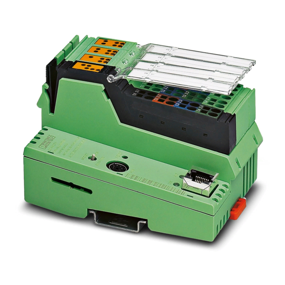
This procedure explains how to assign an IP address to a Phoenix Contact FL IL BK B PAC device, with the IPAssign.exe utility.
Once you opened application, press the Next button. In the next page there are all Phoenix devices found in a list. Check MAC Address correspondence with the one in the label of physical device. If you don't see your device, restart it.
Select your device and press the Next button again. In the next page, configure IP Address and Subnet Mask of the device, and press Next .
Internal configuration
You can configure the Phoenix Contact FL IL 24 BK B PAC device with its web interface, using Internet Explorer to navigate in its IP Address.
Follow the Inline Station link from the left menu. In the next page, press Disable on Plug & Play Mode box, insert ” private ” as password and press Apply to confirm changes.
Now follow the Process Data Monitoring from the left menu. In the next page, set the Process Data Watchdog Timeout field to ” 0 ms ”, insert ” private ” as password and press Apply to confirm changes.
- Phoenix Contact Manuals
- ILC 131 STARTER KIT
- User manual
Phoenix Contact ILC 131 STARTER KIT User Manual
- page of 92 Go / 92
Table of Contents
- Introduction
- Information about this Document
- Content of the ILC 131 STARTERKIT
- Components of the ILC 131 STARTERKIT
- Supported Operating Systems
- Hardware Requirements
- Programming Software
- Required Firmware Version
- Required Programming Software
2 Installed Hardware and Startup
- Structure of the Starter Kit
- ILC 131 STARTERKIT: Installed Components on the Board
- Wiring the Inputs
- ILC 131 STARTERKIT: Example Wiring for the Inputs and the Supply Lines
- Inputs Used in the Example
- Establishing the Ethernet Connection
- ILC 131 STARTERKIT: Example of the Ethernet Cabling
- Connecting the Supply Voltage
- Example Projects
3 Installing the PC WORX EXPRESS Software
- Prior to Installation
- Starting the PC WORX EXPRESS Installation Program
- Starting PC WORX EXPRESS
4 Helpful Information about PC WORX EXPRESS
- Online Help
- User Interface
- IEC Programming Workspace
- Bus Configuration Workspace
- Process Data Workspace
- Icons in the "Bus Structure" Window
- Display in the "Bus Structure" Window
- Examples of Different Device Representations
- Compiling a Project
- Sending a Project
- Project Control Dialog
- Download Options" Dialog Box
- Performing a Cold Restart
- Compiling (Additional Information)
5 Step-By-Step Development of an Example Project
- Creating a New Project
- Project Creation Sequence
- Adapting the Project Information
- Project Information after Creating a New Project
- Assigning the IP Address for the Controller
- Select "PROFINET Configuration
- Bus Configuration: Selecting the Controller
- Figure 5-13 "Message Window" Following Bootp
- Reading in INTERBUS
- Figure 5-14 "View, Connected INTERBUS" Command
- Figure 5-15: Selecting the ILC 131 ETH
- Figure 5-16: Importing Devices into the Project
- Figure 5-17 "Select Device" Window
- Compiling and Sending a Project, and Performing a Cold Restart after Reading in the Bus Topology
- Figure 5-18: Complete Bus Configuration for the Example Project
- Figure 5-19: "Connected INTERBUS" Window: "Selected Control System - Offline
- Program Description
- Figure 5-20 "Firststeps_Ilc131.Mwe" Complete Program
- IEC Programming Worksheet
- Figure 5-21 IEC Programming Workspace
- Entering a Comment
- Figure 5-22: "Objects, Text (Comment)
- Figure 5-23 "Comment" Dialog Box
- Creating Variables
- Figure 5-24: "Options" Dialog Box, "General" Tab: "Hide External Variables
- Figure 5-25: "Variable Properties" Window - Icons
- Step 1: Direct Linking of a Controller Input with a Controller Output Using Onboard Variables
- Figure 5-26 Positioning the Cursor in the Worksheet of the POU "Main
- Figure 5-27 Selecting the Onboard Variable: Input
- Figure 5-28 Variable Properties (System Variables)
- Figure 5-29 System Variable Created: Input
- Figure 5-30 Selecting the Onboard Variable: Output
- Figure 5-31 System Variable Created: Output
- Figure 5-32 Connecting Variables
- Figure 5-33: Compilation Process Completed Without Errors
- Figure 5-34: Project Control Dialog
- Figure 5-35 Download Process
- Figure 5-36: Project Control Dialog
- Step 2: Use of Function Blocks from the Function Block Library
- Figure 5-37 Function Block in the Edit Wizard
- Figure 5-38 Anding
- Step 3: Connecting Function Blocks Using the Example of Clock Generation
- Figure 5-39 Generating a Fixed Clock and Displaying It at a Controller Output
- Figure 5-40 Creating a User Variable
- Figure 5-41 Specifying the Time Constant
- Figure 5-42: Generating a Variable Clock and Displaying It at a Controller Output
- Figure 5-43: Creating a User Variable
- Step 4: Direct Linking of Two Analog Value Variables/Process Data Assignment/Complete Program
- Figure 5-44 Analog Value Variables
- Figure 5-45 Variable Properties (Analog Value)
- Figure 5-46: Process Data Assignment
- Operation and Debug Mode - Viewing Values Online
- Figure 5-47 Variables in Debug Mode: Program Variables
- Figure 5-48: Variables in Debug Mode: Global Variables
- Figure 5-49: Variables in Debug Mode: POU "Main" Variables (Examples)
6 Additional Functions of PC WORX EXPRESS
- Diagnostics with Diag
7 Visualization with Webvisit
- Loading the Visualization on the Controller
- Starting the Visualization
A Appendixes
- List of Figures
- List of Tables
Advertisement
Quick Links
- 1 Programming Software
- 2 Wiring the Inputs
- 3 Assigning the Ip Address for the Controller
- 4 Diagnostics with Diag
- Download this manual
- Table of Contents 5
- A Appendixes 87
Related Manuals for Phoenix Contact ILC 131 STARTER KIT

Summary of Contents for Phoenix Contact ILC 131 STARTER KIT
- Page 1 Installing and starting up the ILC 131 STARTER KIT User manual...
- Page 2 User manual Installing and starting up the ILC 131 STARTER KIT 2014-07-18 Designation: UM QS EN ILC 131 STARTERKIT Revision: Order No.: — This user manual is valid for: Designation Order No. ILC 131 STARTERKIT 2701835 PHOENIX CONTACT 105724_en_01...
- Page 3 How to contact us Internet Up-to-date information on Phoenix Contact products and our Terms and Conditions can be found on the Internet at: phoenixcontact.com Make sure you always use the latest documentation.
- Page 4 The receipt of technical documentation (in particular user documentation) does not constitute any further duty on the part of Phoenix Contact to furnish information on modifications to products and/or technical documentation. You are responsible to verify the suitability and intended use of the products in your specific application, in particular with regard to observing the applicable standards and regulations.
Page 5: Table Of Contents
- Page 6 Operation and debug mode – viewing values online..........65 Additional functions of PC WORX EXPRESS ................69 Diagnostics with Diag+ ..................69 Visualization with WebVisit ......................77 General........................77 Loading the visualization on the controller ............80 Starting the visualization ..................84 Appendixes..........................87 List of figures .......................87 List of tables ......................91 PHOENIX CONTACT 105724_en_01...
Page 7: General
Page 8: components of the ilc 131 starterkit, page 9: system requirements.
- Page 10 ILC 131 STARTERKIT PHOENIX CONTACT 105724_en_01...
Page 11: Installed Hardware And Startup
Page 12: wiring the inputs, page 13: establishing the ethernet connection, page 14: starting up the ilc 131 starterkit, page 15: installing the pc worx express software, page 16: starting pc worx express, page 17: helpful information about pc worx express, page 18: toolbars, page 19: workspaces, page 20: bus configuration workspace.
- Page 21 “normal” window. Its size can be modified and it can be moved to any position on the screen. In order to re-dock the window, i.e., to reinsert it in the desktop, double-click on the title bar. 105724_en_01 PHOENIX CONTACT...
Page 22: Bus Structure" Window
Page 23: display in the "bus structure" window, page 24: examples of different device representations, page 25: compiling and transmitting a project and performing a cold restart, page 26: download options" dialog box.
- Page 27 Close the “Download Options” dialog box once you have made the necessary settings for your project. • To do this, click on “Download” in the Project Control Dialog. The project is now in the RAM of the controller. 105724_en_01 PHOENIX CONTACT...
Page 28: Performing A Cold Restart
Page 29: step-by-step development of an example project, page 30: creating a project in pc worx express, establishing a connection to the controller, and reading in interbus devices.
- Page 31 Figure 5-2 “New Project” dialog box: project templates • Select the “File, Save Project As/Zip Project As...” command. • Enter a project name (here: FirstSteps_ILC131) and save the project. Figure 5-3 “Save/Zip project as” window 105724_en_01 PHOENIX CONTACT...
Page 32: Adapting The Project Information
- Page 33 If you manually assign IP parameters that are outside the defined area, they will not be accepted. Example IP addresses are shown in the following screenshots. Adapt the IP address to your system. 105724_en_01 PHOENIX CONTACT...
Page 34: Assigning The Ip Address For The Controller
Page 35: select "profinet configuration, page 36: bus configuration: selecting the controller.
- Page 37 DCP PROFINET protocol, you can skip Section 5.1.4.2, “BootP server”. The connecting cable (RS-232 cable) PRG CAB MINI DIN (Order No. 2730611) is available as an optional accessory for connecting the controller to a PC via the serial interface. 105724_en_01 PHOENIX CONTACT...
- Page 38 Select the Inline controller node (here: “ILC 131 ETH”). • Select the “IP Settings” tab in the “Device Details” window. • Enter the MAC address of the controller (see Figure 5-10 on page 39). It is printed on the device. It starts with 00.A0.45. PHOENIX CONTACT 105724_en_01...
- Page 39 “Extras, BootP/SNMP/TFTP-Configuration...” menu • Click on the “Activate BootP” button. Figure 5-12 “Activate BootP” button • Perform a cold restart for the controller. To do this, switch the supply voltage off and then on again after about two seconds. 105724_en_01 PHOENIX CONTACT...
Page 40: Figure 5-13 "Message Window" Following Bootp
Page 41: reading in interbus, page 42: figure 5-15: selecting the ilc 131 eth, page 43: figure 5-17 "select device" window, page 44: compiling and sending a project, and performing a cold restart after reading in the bus topology, page 45: firststeps_ilc131" example project, page 46: program description.
- Page 47 For more information about installing and starting up the example visualization on the controller and the requirements for your web browser, refer to Section 7, “Visualization with WebVisit”. 105724_en_01 PHOENIX CONTACT...

Page 48: Creating The Program
Page 49: entering a comment, page 50: creating variables, page 51: step 1: direct linking of a controller input with a controller output using onboard variables, page 52: figure 5-28 variable properties (system variables), page 53: figure 5-30 selecting the onboard variable: output, page 54: figure 5-33: compilation process completed without errors, page 55: figure 5-36: project control dialog, page 56: step 2: use of function blocks from the function block library.
- Page 57 Activate switches 0 and 1 of the switch module to test the program. If all of the steps described above have been carried out properly, the I1 and Q1 LEDs light up on the controller when switches 0 and 1 are set to ON simultaneously. 105724_en_01 PHOENIX CONTACT...
Page 58: Step 3: Connecting Function Blocks Using The Example Of Clock Generation
Page 59: figure 5-40 creating a user variable, page 60: figure 5-42: generating a variable clock and displaying it at a controller output, page 61: figure 5-43: creating a user variable, page 62: step 4: direct linking of two analog value variables/process data assignment/complete program, page 63: figure 5-45 variable properties (analog value), page 64: figure 5-46: process data assignment, page 65: operation and debug mode - viewing values online, page 66: figure 5-48: variables in debug mode: global variables, page 67: figure 5-49: variables in debug mode: pou "main" variables (examples).
- Page 68 ILC 131 STARTERKIT PHOENIX CONTACT 105724_en_01...
Page 69: Additional Functions Of Pc Worx Express
- Page 70 “Bus Info” tab In the following dialog box, the “Bus Info” tab is displayed (see Figure 6-2). Figure 6-2 “Bus Info” tab (start screen) “Settings” tab • Select the “Settings” tab (see Figure 6-3). Figure 6-3 “Settings” tab PHOENIX CONTACT 105724_en_01...
- Page 71 Which device information should be displayed (e.g., device number) and – How often the diagnostic data should be updated (e.g., manually when changing tabs). “Bus Architecture” tab • Select the “Bus Architecture” tab (see Figure 6-4). Figure 6-4 “Bus Architecture” tab (no error) 105724_en_01 PHOENIX CONTACT...
- Page 72 ILC 131 STARTERKIT An error is simulated. The IB IL AI 2/SF-ME Inline terminal is removed. Figure 6-5 “Bus Architecture” tab (error) PHOENIX CONTACT 105724_en_01...
- Page 73 Additional functions of PC WORX EXPRESS “Solution” tab • Select the “Solution” tab. Here, information is provided about how to remove the error. Figure 6-6 “Solution” tab • Remove the error (here: insert Inline terminal again). 105724_en_01 PHOENIX CONTACT...
- Page 74 • In this case, click on “Acknowledge all Peripheral Faults” to reset the error message for the corresponding module. • Click on “Start Bus” again to start up the entire bus configuration again following error removal. PHOENIX CONTACT 105724_en_01...
- Page 75 Additional functions of PC WORX EXPRESS Successful error removal with error-free bus operation is indicated in the status bar: Figure 6-8 “Action” tab: bus running without errors (RUN) 105724_en_01 PHOENIX CONTACT...
- Page 76 ILC 131 STARTERKIT PHOENIX CONTACT 105724_en_01...
Page 77: Visualization With Webvisit
- Page 78 (xxx = project name, FirstSteps_ILC131 in the example). When you enter this path, the path for the pdd.csv file is updated automatically. Please see Figure 7-6 on page 81. For further information about using WebVisit, please refer to the corresponding documentation. PHOENIX CONTACT 105724_en_01...
- Page 79 A drop-down menu appears in the cell to the right of the “Language” cell. • Select the desired language. Figure 7-4 “Tool Configurations” window • Confirm your selection with “OK”. The language setting takes effect after WebVisit is restarted. 105724_en_01 PHOENIX CONTACT...
Page 80: Loading The Visualization On The Controller
- Page 81 • Download the project to the controller via the “Project, Download project...” menu item. dialog box • In the “Connect” area, set the IP address of the controller under “Server” (“192.168.0.2” in the example, see Figure 7-7). 105724_en_01 PHOENIX CONTACT...
- Page 82 ILC 131 STARTERKIT Figure 7-7 WebVisit FTP download to the controller • Click on the “Connect” button. Figure 7-8 WebVisit connected to the controller • Click on the “Download project” button. PHOENIX CONTACT 105724_en_01...
- Page 83 Loading the WebVisit project to the controller The progress indicator shows the transmission status. The visualization project has been transmitted to the controller. The visualization can now be displayed via your web browser. Read more in Section “Starting the visualization” on page 84. 105724_en_01 PHOENIX CONTACT...
Page 84: Starting The Visualization
- Page 85 Click on the “Analog Input” button to view the visualization of the analog input value. value Figure 7-11 Display of the analog input value (Input_Analog variable) • Adjust the starter kit potentiometer to change the level of the bar graph. 105724_en_01 PHOENIX CONTACT...
- Page 86 ILC 131 STARTERKIT PHOENIX CONTACT 105724_en_01...
Page 87: Appendixes
- Page 88 Variable Properties (analog value) ............63 Figure 5-46: Process Data Assignment ..............64 Figure 5-47: Variables in debug mode: program variables ........65 Figure 5-48: Variables in debug mode: global variables ..........66 Figure 5-49: Variables in debug mode: POU “Main” variables (examples) ....67 PHOENIX CONTACT 105724_en_01...
- Page 89 WebVisit FTP download to the controller ..........82 Figure 7-8: WebVisit connected to the controller ..........82 Figure 7-9: Loading the WebVisit project to the controller ........83 Figure 7-10: Visualization start page ...............84 Figure 7-11: Display of the analog input value (Input_Analog variable) ....85 105724_en_01 PHOENIX CONTACT...
- Page 90 ILC 131 STARTERKIT PHOENIX CONTACT 105724_en_01...
Page 91: List Of Tables
- Page 92 ILC 131 STARTERKIT PHOENIX CONTACT 105724_en_01...
Rename the bookmark
Delete bookmark, delete from my manuals, upload manual.
CONFIG+ - Configuration and diagnostic software 2868059
Config+ full version for configuration and diagnostics of an INTERBUS system
Product details
Config+ from Phoenix Contact is the ideal software solution for configuring INTERBUS networks. The clear user interface allows you to assign addresses using drag & drop and to reliably configure even complex topologies. In addition, the Ethernet devices used can also be mapped and diagnosed. For reliable troubleshooting in INTERBUS networks, the integrated Diag+ diagnostics tool can be used.
Compatible products
IBS S7 400 DSC/I-T - Termination board 2719962

IBS S7 300 DSC-T - Termination board 2719975

IBS PCI SC/RI/I-T - Termination board 2730080

IBS PCI SC/RI-LK - Termination board 2730187

IBS PCI SC/I-T - Termination board 2725260

FL IL 24 BK-B-PAC - Bus coupler 2862327

FL NP PND-4TX IB - Proxy 2985974

FL NP PND-4TX IB-LK - Proxy 2985929

FLM BK ETH M12 DI 8 M12-2TX - Bus coupler 2736916

IL ETH BK DI8 DO4 2TX-PAC - Bus coupler 2703981

IBS USC4-2 - Masterboard 2812209
Your advantages.

Pixelink Support
Ip address assignment tool.
Modified on: Mon, 6 Feb, 2023 at 2:38 PM
Pixelink Cameras and IP addresses
Network based Pixelink cameras (currently, only cameras with a Gigabit Ethernet interface) must have a valid IP address assigned to it in order to function correctly. This tool can be used to manage the IP address assignment for our PL-B and PL-X series GigE cameras. The program has two operational modes; dialog based interactive mode , and command line based mode . Both modes of operation will allow you to manage IP address assignment using either dynamic (or automatic) IP address assignment, or static IP address assignment.
Static vs. Dyanmic IP Address Assignment
Dynamic IP Address Assignment, or what Microsoft Windows refers to as automatic, is the technique used by the camera by default. That is, the camera will query the network to which it is attached, to try to assign itself an IP address appropriate for the network. Should your network have a DHCP (Dynamic Host Configuration Protocol) server, then the camera will receive IP configuration information from the server. In the absence of a DHCP server, the camera will use LLA (Link-Local Address) to assign itself an IP address. It’s noteworthy that the LLA process can take up to a minute to resolve an IP address, so DHCP is generally the preferred technique for dynamic IP address assignment. A camera which has used LLA to determine its network address, can be identified by having an address on the 169.254.0.0/16 IP subnet (having an IP address of 169.254.ddd.ddd and a subnet mask of 255.255.0.0).
Static IP Address Assignment requires the user to assign the IP configuration to the camera (using this tool). This technique requires more network knowledge, and is typically only used in point-to-point connections, or in very small networks.
If you are unclear on what IP address assignment technique to use, or what IP address to assign, looking at the "Internet Protocol (TCP/IP) Properties" page within Windows is a good place to start (found under Start => ControlPanel => Network Connections => Properties of your NIC => Internet Protocol (TCP/IP) Properties).
In Windows 10 , the IP Properties Page can be found under Start -> Settings -> Network and Internet
Next, select Ethernet, and click Change Adapter Options

Right click on the Ethernet connection that you're connected to, and select Properties
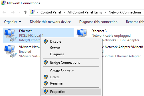
Scroll down the list and select Internet Protocol Version 4, and then click Properties:

This will bring you to the IP Properties window:
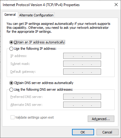
If your NIC is set to "Obtain an IP address automatically", then your camera should be usable without any further configuration, as it too will use Dynamic IP address assignment. However, if your NIC is set to "Use the following IP address" (as shown in the very first screenshot), then you will have to use static IP address assignment for your camera.
Choose an IP address which is not being used by any other device on the network. Choosing an IP address which is one greater than the NICs IP address is often a good choice (EG. If the NICs IP Address is: 192.168.1.10 => use IP Address: 192.168.1.11). You should set the cameras subnet mask and default gateway to the same values used by the NIC (the defaults used by this program).
Locating the IP Address Assignment Tool
The IP Address Tool (PxLlpAddress.exe) can be found in the Tools folder after installing Pixelink Capture or the Pixelink SDK, if the option to install GigE Drivers is selected during installation. The default location for the Tools folder is:
C:\Program Files (x86)\PixeLINK\Tools\PxLlpAddress.exe
If you are unable to find the IP Address Tool, please uninstall the Pixelink camera software (Pixelink Capture or the SDK), and reinstall the software by following the instructions below:
During Pixelink Capture installation
If you're installing release 10.7 (and above), click the box to Install GigE drivers, shown on the first window of the installer.
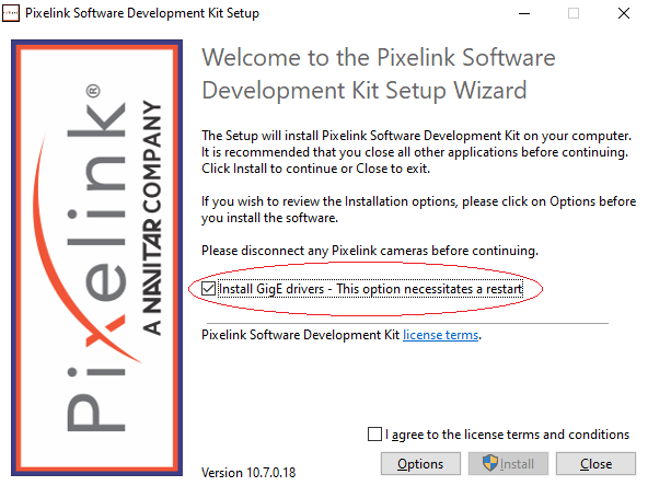
For earlier releases:
1. Select Options
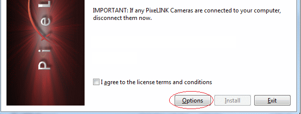
2. Select GigE Driver and press "OK". This option will load the GigE driver as well as the tools for your camera.

3. Proceed with the installation. After the installation is complete, you will be able to find IP Address Tool in the Tools folder.
If you have any questions about using the IP Address tool, you can contact Pixelink Support via the website , or by email at [email protected] .
Did you find it helpful? Yes No
Related Articles

IMAGES
VIDEO
COMMENTS
IPAssign is an easy to use tool for setting the IP address of devices which rely on BOOTP. No installation or administrative rights are required to use IPAssign. ... you can filter out all of the devices except those from Phoenix Contact. Technical data. System properties. System requirements: Languages supported: English: Commercial data. Item ...
Config+ from Phoenix Contact is the ideal software solution for configuring INTERBUS networks. The clear user interface allows you to assign addresses using drag & drop and to reliably configure even complex topologies. In addition, the Ethernet devices used can also be mapped and diagnosed. For reliable troubleshooting in INTERBUS networks ...
FL WLAN 1100/1101 3.1.2 General sequence for startup During startup, supply the device with operating voltage (nominal value: 24 V DC). The as- signment of the connector is shown in Unknown source of cross-reference. In order to start up the device, the device must first be assigned an IP address.
IAS Applications Engineer Donnie Dauphin is back! In the latest in his tutorial series, Donnie walks you through IP assignment and assigning an IP address vi...
EASY CONFIGURATIONEtherNet/IP Made Easy is a freeware tool for configuring Phoenix Contact managed switches and I/O for any EtherNet/IP application. It supports multiple wired or wireless adaptors and provides network discovery and IP management functions. ... The freeware includes wizard-style execution, and no software installation or SNMP ...
July 21, 2009 - Phoenix Contact introduces EtherNet/IP Made Easy, a freeware tool that makes configuring Phoenix Contact managed switches and I/O for any EtherNet/IP application easy and quick. With simple, wizard-style execution, EtherNet/IP Made Easy takes the user through all of the key steps of EtherNet/IP network device configuration. No ...
EtherNet/IP Made Easy is a freeware tool for configuring Phoenix Contact managed switches and I/O for any EtherNet/IP application. It carrier multiple wired or cordless fixture and provides network discover and IP management functions. ... To freeware includes wizard-style execution, and negative software installation or SNMP services are ...
You can both read and assign an IP address to a Phoenix Contact Axioline IO block. Additionally, you can set it to static and disable DHCP.Helping you becom...
In this video you'll learn to how to use the Ethernet/IP Made Easy tool to configure Phoenix Contact Inline Modular I/O and switches for use in Ethernet/IP n...
Phenomena Request FL WLAN 1100 Manual Online: assigning the ip address via bootp (with ipassign), Assigning The Ip Address Using Ipassign.exe. This Section Explains Industrial Address Assign Using To ''Ip Assignment Tool'' Screen Soft- Waste (Ipassign.exe). This Software Can Be Downloaded...
BootP. IPAssign is a free BootP server. Step through the IPAssign wizard and assign the IL ETH BK DI8 DO4 2TX-PAC an IP of 192.168.254.13. 5. Once an IP address has been assign, open an Internet browser and navigate to IP address 192.168.254.13. Navigate to the 'Inline Station' folder and to the 'Services' menu.
Easy Configuration
In this video, we'll demonstrate the simple configuration of Phoenix Contact's new EtherNet/IP Gateway using its integrated web server. We'll also configure ...
Assign IP Address. This procedure explains how to assign an IP address to a Phoenix Contact FL IL BK B PAC device, with the IPAssign.exe utility. Once you opened application, press the Next button. In the next page there are all Phoenix devices found in a list. Check MAC Address correspondence with the one in the label of physical device. If ...
Phoenix Contact recommends that you assign the IP address via the DCP PROFINET protocol. 5.1.4.1 Dynamic Configuration Protocol (DCP) The Inline controller from firmware version 4.20 or later and from PC Worx version... Page 35: Select "Profinet Configuration Figure 5-5 Select "PROFINET Configuration ..." The "PROFINET" window is opened.
IL ETH BK DI8 DO4 2TX-PAC: IP ASSIGNMENT & WATCHDOG 7621_en_00 PHOENIX CONTACT 4 IP Address Assignment With IPAssign.exe Step 1: Download and Execute Program • On the Internet, select the link www.download.phoenixcontact.com. • In the search mask, enter the order number for the bus coupler. The BootP IP addressing tool is under ...
http://www.phoenixcontact.com/controlThis Phoenix Contact PC Worx video tutorial will show Easy Automation users how to assign an IP address to the controller.
Config+ from Phoenix Contact is the ideal software solution for configuring INTERBUS networks. The clear user interface allows you to assign addresses using drag & drop and to reliably configure even complex topologies. In addition, the Ethernet devices used can also be mapped and diagnosed. For reliable troubleshooting in INTERBUS networks ...
Locating the IP Address Assignment Tool. The IP Address Tool (PxLlpAddress.exe) can be found in the Tools folder after installing Pixelink Capture or the Pixelink SDK, if the option to install GigE Drivers is selected during installation. The default location for the Tools folder is: C:\Program Files (x86)\PixeLINK\Tools\PxLlpAddress.exe.
PC WORX 6.30 PHOENIX CONTACTStep 1. Download: BootP IP addressing tool.Step 2. Open BootP IP addressing tool.Step 3: Click next to continue.Step 4: Checked: ...