Academia.edu no longer supports Internet Explorer.
To browse Academia.edu and the wider internet faster and more securely, please take a few seconds to upgrade your browser .
Enter the email address you signed up with and we'll email you a reset link.
- We're Hiring!
- Help Center


Sustainable Design of Earthquake-Resistant Buildings Through Case Studies

2020, Gulf Conference on Sustainable Built Environment
Related Papers
International Journal of Advance Research and Innovative Ideas in Education
Harshit Suchak
IOSR Journal of Engineering
KUUNREDDY SRINIVASREDDY 16PHD0571
Amita Sinvhal
Journal of Earthquake Engineering
Charles-Darwin Annan
Tiziana Rossetto
Earthquake Engineering & Structural Dynamics
Marios Phocas
Andras Recski
Natural Science
Nikos Pnevmatikos
Ioannis Vayas
International Journal of Computational Methods and Experimental Measurements
Wim Debacker
RELATED PAPERS
fragole rosso
Gabriela Liñan
Dwiasih Kartika Ningrum
International Journal of Modern Physics: Conference Series
G. Donzella
Markus Bühner
Francesco Marino
Hydrological Processes
klaas metselaar
Cardiovascular Journal
Farhana Kazmi
African journal of reproductive health
moussa sissoko
Boris Liebl
Progress in Neuro-Psychopharmacology and Biological Psychiatry
Alex Ballesteros
Glen Jankowski
Darko Andronikov
European journal of biochemistry
Dominique Pantaloni
Richard Patey
International Journal of Chemical Studies
Jogendra Soren
Osteoarthritis and Cartilage
Dawn McGuire MD
ICF journal
Karl Andersen
Enfermedades Infecciosas y Microbiología Clínica
Camilo Gonzalez
European Journal of Drug Metabolism and Pharmacokinetics
Pablo Andrade
Abdul Muqsith
RELATED TOPICS
- We're Hiring!
- Help Center
- Find new research papers in:
- Health Sciences
- Earth Sciences
- Cognitive Science
- Mathematics
- Computer Science
- Academia ©2024

- Design Objectives
- Building Types
- Space Types
- Design Disciplines
- Guides & Specifications
- Resource Pages
- Project Management
- Building Commissioning
- Operations & Maintenance
- Building Information Modeling (BIM)
- Unified Facilities Guide Specifications (UFGS)
- Unified Facilities Criteria (UFC)
- VA Master Specifications (PG-18-1)
- Design Manuals (PG-18-10)
- Department of Energy
- General Services Administration
- Department of Homeland Security
- Department of State
- Course Catalog
- Workforce Development
- Case Studies
- Codes & Standards
- Industry Organizations
Seismic Design Principles
by Gabor Lorant, FAIA Lorant Group, Inc. / Gabor Lorant Architects, Inc.
- Introduction
Within This Page
Description, application, relevant codes and standards, additional resources.
This resource page provides an introduction to the concepts and principles of seismic design, including strategies for designing earthquake-resistant buildings to ensure the health, safety , and security of building occupants and assets .
The essence of successful seismic design is three-fold. First, the design team must take a multi-hazard approach towards design that accounts for the potential impacts of seismic forces as well as all the major hazards to which an area is vulnerable. Second, performance-based requirements, which may exceed the minimum life safety requirements of current seismic codes, must be established to respond appropriately to the threats and risks posed by natural hazards on the building's mission and occupants. Third, and as important as the others, because earthquake forces are dynamic and each building responds according to its own design complexity, it is essential that the design team work collaboratively and have a common understanding of the terms and methods used in the seismic design process.
In addition, as a general rule, buildings designed to resist earthquakes should also resist blast (terrorism) or wind, suffering less damage. For example, were the Oklahoma Federal Building designed to seismic design standards, the damage caused by the blast would have been much less (refer to MAT Report FEMA 277 ). For more information, see WBDG Designing Buildings to Resist Explosive Threats section on Seismic vs. Blast Protection.
About half of the states and territories in the United States—more than 109 million people and 4.3 million businesses—and most of the other populous regions of the earth are exposed to risks from seismic hazards. In the U.S. alone, the average direct cost of earthquake damage is estimated at $1 billion/year while indirect business losses are estimated to exceed $2 billion/year.

Seismicity of the United States
A. Origin and Measurement of Earthquakes
Plate tectonics, the cause of earthquakes.
Earthquakes are the shaking, rolling, or sudden shock of the earth's surface. Basically, the Earth's crust consists of a series of "plates" floating over the interior, continually moving (at 2 to 130 millimeters per year), spreading from the center, sinking at the edges, and being regenerated. Friction caused by plates colliding, extending, or subducting (one plate slides under the other) builds up stresses that, when released, causes an earthquake to radiate through the crust in a complex wave motion, producing ground failure (in the form of surface faulting [a split in the ground], landslides, liquefaction, or subsidence), or tsunami. This, in turn, can cause anywhere from minor damage to total devastation of the built environment near where the earthquake occurred.

Ground failure-landslide—Alaska, 1964
Liquefaction damage—Niigata, Japan 1964

Saada Hotel (before)—Agadir, Morocco, 1960
Saada Hotel (after) ground shaking damage—Agadir, Morocco, 1960
Measuring Seismic Forces
In order to characterize or measure the effect of an earthquake on the ground (a.k.a. ground motion), the following definitions are commonly used:
- 0.001g or 1 cm/sec 2 is perceptible by people
- 0.02 g or 20 cm/sec 2 causes people to lose their balance
- 0.50g is very high but buildings can survive it if the duration is short and if the mass and configuration has enough damping
- Velocity (or speed) is the rate of change of position, measured in centimeters per second.
- Displacement is the distance from the point of rest, measured in centimeters.
- Duration is the length of time the shock cycles persists.
- Magnitude is the "size" of the earthquake, measured by the Richter scale, which ranges from 1-10. The Richter scale is based on the maximum amplitude of certain seismic waves, and seismologists estimate that each unit of the Richter scale is a 31 times increase of energy. Moment Magnitude Scale is a recent measure that is becoming more frequently used.
If the level of acceleration is combined with duration, the power of destruction is defined. Usually, the longer the duration, the less acceleration the building can endure. A building can withstand very high acceleration for a very short duration in proportion with damping measures incorporated in the structure.
Intensity is the amount of damage the earthquake causes locally, which can be characterized by the 12 level Modified Mercalli Scale (MM) where each level designates a certain amount of destruction correlated to ground acceleration. Earthquake damage will vary depending on distance from origin (or epicenter), local soil conditions, and the type of construction.
B. Effects of Earthquakes on Buildings
Seismic Terminology (For definitions of terms used in this resource page, see Glossary of Seismic Terminology )
The aforementioned seismic measures are used to calculate forces that earthquakes impose on buildings. Ground shaking (pushing back and forth, sideways, up and down) generates internal forces within buildings called the Inertial Force (F Inertial ), which in turn causes most seismic damage.
F Inertial = Mass (M) X Acceleration (A).
The greater the mass (weight of the building), the greater the internal inertial forces generated. Lightweight construction with less mass is typically an advantage in seismic design. Greater mass generates greater lateral forces, thereby increasing the possibility of columns being displaced, out of plumb, and/or buckling under vertical load (P delta Effect).
Earthquakes generate waves that may be slow and long, or short and abrupt. The length of a full cycle in seconds is the Period of the wave and is the inverse of the Frequency . All objects, including buildings, have a natural or fundamental period at which they vibrate if jolted by a shock. The natural period is a primary consideration for seismic design, although other aspects of the building design may also contribute to a lesser degree to the mitigation measures. If the period of the shock wave and the natural period of the building coincide, then the building will "resonate" and its vibration will increase or "amplify" several times.
Height is the main determinant of fundamental period—each object has its own fundamental period at which it will vibrate. The period is proportionate to the height of the building.
The soil also has a period varying between 0.4 and 1.5 sec., very soft soil being 2.0 sec. Soft soils generally have a tendency to increase shaking as much as 2 to 6 times as compared to rock. Also, the period of the soil coinciding with the natural period of the building can greatly amplify acceleration of the building and is therefore a design consideration.
Tall buildings will undergo several modes of vibration, but for seismic purposes (except for very tall buildings) the fundamental period, or first mode is usually the most significant.
Seismic Design Factors
The following factors affect and are affected by the design of the building. It is important that the design team understands these factors and deal with them prudently in the design phase.
Torsion : Objects and buildings have a center of mass, a point by which the object (building) can be balanced without rotation occurring. If the mass is uniformly distributed then the geometric center of the floor and the center of mass may coincide. Uneven mass distribution will position the center of mass outside of the geometric center causing "torsion" generating stress concentrations. A certain amount of torsion is unavoidable in every building design. Symmetrical arrangement of masses, however, will result in balanced stiffness against either direction and keep torsion within a manageable range.
Damping : Buildings in general are poor resonators to dynamic shock and dissipate vibration by absorbing it. Damping is a rate at which natural vibration is absorbed.
Ductility : Ductility is the characteristic of a material (such as steel) to bend, flex, or move, but fails only after considerable deformation has occurred. Non-ductile materials (such as poorly reinforced concrete) fail abruptly by crumbling. Good ductility can be achieved with carefully detailed joints.
Strength and Stiffness : Strength is a property of a material to resist and bear applied forces within a safe limit. Stiffness of a material is a degree of resistance to deflection or drift (drift being a horizontal story-to-story relative displacement).
Building Configuration : This term defines a building's size and shape, and structural and nonstructural elements. Building configuration determines the way seismic forces are distributed within the structure, their relative magnitude, and problematic design concerns.
- Low Height to Base Ratios
- Equal Floor Heights
- Symmetrical Plans
- Uniform Sections and Elevations
- Maximum Torsional Resistance
- Short Spans and Redundancy
- Direct Load Paths
- Irregular Configuration buildings are those that differ from the "Regular" definition and have problematic stress concentrations and torsion.

View enlarged illustration
Buildings seldom overturn—they fall apart or "pancake"
Soft First Story is a discontinuity of strength and stiffness for lateral load at the ground level.
Discontinuous Shear Walls do not line up consistently one upon the other causing "soft" levels.
Variation in Perimeter Strength and Stiffness such as an open front on the ground level usually causes eccentricity or torsion.
Reentrant Corners in the shapes of H , L , T , U , + , or [] develop stress concentration at the reentrant corner and torsion. Seismic designs should adequately separate reentrant corners or strengthen them.
Knowledge of the building's period, torsion, damping, ductility, strength, stiffness, and configuration can help one determine the most appropriate seismic design devices and mitigation strategies to employ.
C. Seismic Design Strategies and Devices
Diaphragms : Floors and roofs can be used as rigid horizontal planes, or diaphragms, to transfer lateral forces to vertical resisting elements such as walls or frames.
Shear Walls : Strategically located stiffened walls are shear walls and are capable of transferring lateral forces from floors and roofs to the foundation.
Braced Frames : Vertical frames that transfer lateral loads from floors and roofs to foundations. Like shear walls, Braced Frames are designed to take lateral loads but are used where shear walls are impractical.
Moment-Resistant Frames : Column/beam joints in moment-resistant frames are designed to take both shear and bending thereby eliminating the space limitations of solid shear walls or braced frames. The column/beam joints are carefully designed to be stiff yet to allow some deformation for energy dissipation taking advantage of the ductility of steel (reinforced concrete can be designed as a Moment-Resistant Frame as well).

Concentric Braced Frame
Eccentric Braced Frame, with link beams
Energy-Dissipating Devices : Making the building structure more resistive will increase shaking which may damage the contents or the function of the building. Energy-Dissipating Devices are used to minimize shaking. Energy will dissipate if ductile materials deform in a controlled way. An example is Eccentric Bracing whereby the controlled deformation of framing members dissipates energy. However, this will not eliminate or reduce damage to building contents. A more direct solution is the use of energy dissipating devices that function like shock absorbers in a moving car. The period of the building will be lengthened and the building will "ride out" the shaking within a tolerable range.

Base Isolation Bearings are used to modify the transmission of the forces from the ground to the building
Base Isolation : This seismic design strategy involves separating the building from the foundation and acts to absorb shock. As the ground moves, the building moves at a slower pace because the isolators dissipate a large part of the shock. The building must be designed to act as a unit, or "rigid box", of appropriate height (to avoid overturning) and have flexible utility connections to accommodate movement at its base. Base Isolation is easiest to incorporate in the design of new construction. Existing buildings may require alterations to be made more rigid to move as a unit with foundations separated from the superstructure to insert the Base Isolators. Additional space (a "moat") must be provided for horizontal displacement (the whole building will move back and forth a whole foot or more). Base Isolation retrofit is a costly operation that is most commonly appropriate in high asset value facilities and may require partial or the full removal of building occupants during installation.

Passive Energy Dissipation includes the introduction of devices such as dampers to dissipate earthquake energy producing friction or deformation.
The materials used for Elastomeric Isolators are natural rubber, high-damping rubber, or another elastomer in combination with metal parts. Frictive Isolators are also used and are made primarily of metal parts.
Tall buildings cannot be base-isolated or they would overturn. Being very flexible compared to low-rise buildings, their horizontal displacement needs to be controlled. This can be achieved by the use of Dampers , which absorb a good part of the energy making the displacement tolerable. Retrofitting existing buildings is often easier with dampers than with base isolators, especially if the application is external or does not interfere with the occupants.
There are many types of dampers used to mitigate seismic effects, including:
- Hysteric dampers utilize the deformation of metal parts
- Visco-elastic dampers stretch an elastomer in combination with metal parts
- Frictive dampers use metal or other surfaces in friction
- Viscous dampers compress a fluid in a piston-like device
- Hybrid dampers utilize the combination of elastomeric and metal or other parts
D. Nonstructural Damage Control
All items, which are not part of the structural system, are considered as "nonstructural", and include such building elements as:
- Exterior cladding and curtain walls
- Parapet walls
- Canopies and marquees
- Chimneys and stacks
- Partitions, doors, windows
- Suspended ceilings
- Routes of exit and entrance
- Mechanical, Plumbing, Electrical and Communications equipment
- Furniture and equipment
These items must be stabilized with bracing to prevent their damage or total destruction. Building machinery and equipment can be outfitted with seismic isolating devices, which are modified versions of the standard Vibration Isolators.
Loss arising from nonstructural damage can be a multiple of the structural losses. Loss of business and failure of entire businesses was very high in the Loma Prieta, Northridge, and Kobe earthquakes due to both structural and nonstructural seismic damages.
The principles and strategies of seismic design and construction are applied in a systematic approach that matches an appropriate response to specific conditions through the following major steps:
1. Analyze Site Conditions
The location and physical properties of the site are the primary influences the entire design process. The following questions can serve as a checklist to identify seismic design objectives.
- Where is the location of the nearest fault?
- Are there unconsolidated natural or man-made fills present?
- Is there a potential for landslide or liquefaction on or near the site?
- Are there vulnerable transportation, communication, and utilities connections?
- Are there any hazardous materials on the site to be protected?
- Is there potential for battering by adjacent buildings?
- Is there exposure to potential flood from tsunami, seiche, or dam failure?
Consider mission critical or business continuity threats of seismicity on adjacent sites or elsewhere in the vicinity that may render the project site inaccessible or causes the loss of utilities, threat of fire, or the release of toxic materials to the site. Conduct subsurface investigations to discover loose soils or uncontrolled fill that could increase ground motion. Hard dense soils remain more stable, while solid dense rock is the most predictable and seismically safe building base.
2. Establish Seismic Design Objectives
A performance-based approach to establishing seismic design objectives is recommended. This determines a level of predictable building behavior by responding to the maximum considered earthquake. A threat/vulnerability assessment and risk analysis can be used to define the level of performance desired for the building project. Some suggested seismic design performance goals are:
- Conform to local building codes providing "Life Safety," meaning that the building may collapse eventually but not during the earthquake.
- Design for repairable structural damage, required evacuation of the building, and acceptable loss of business for stipulated number of days.
- Design for repairable nonstructural damage, partial or full evacuation, and acceptable loss of business for stipulated number of days due to repair.
- Design for repairable structural damage, no evacuation required, and acceptable loss of business for stipulated number of days due to repair.
- No structural damage, repairable nonstructural damage, no evacuation, and acceptable loss of business for stipulated number of days due to repair.
- No structural or nonstructural damage, and no loss of business caused by either (excluding damage to tenants' own equipment such as file cabinets, bookshelves, furniture, office equipment etc. if not properly anchored).
Regarding the magnitude of the earthquake it may also be stipulated as "Low," "Moderate," or "Large" as another matrix of grading threat and establishing corresponding building performance goals.
3. Select/Design Appropriate Structural Systems
Seismic design objectives can greatly influence the selection of the most appropriate structural system and related building systems for the project. Some construction type options, and corresponding seismic properties, are:
- Wood or timber frame (good energy absorption, light weight, framing connections are critical).
- Reinforced masonry walls (good energy absorption if walls and floors are well integrated; proportion of spandrels and piers are critical to avoid cracking)
- Reinforced concrete walls (good energy absorption if walls and floors well integrated; proportion of spandrels and piers are critical to avoid cracking)
- Steel frame with masonry fill-in walls (good energy absorption if bay sizes are small and building plan is uniform)
- Steel frame, braced (extensive bracing, detailing, and proportions are important)
- Steel frame, moment-resisting (good energy absorption, connections are critical)
- Steel frame, eccentrically braced (excellent energy absorption, connections are critical)
- Pre-cast concrete frame (poor performer without special energy absorbing connections)
Structural and architectural detailing and construction quality control is very important to ensure ductility and natural damping and to keep damages to a limited and repairable range. The prospect of structural and nonstructural damage is not likely to be eliminated without the prudent use of energy-dissipating devices. The cost of adding energy-dissipating devices is in the range of 1–2% of the total structural cost. This is not a large number, particularly when related to the life-cycle cost of the building. Within a 30–50 year life cycle the cost is negligible.
Many building codes and governmental standards exist pertaining to design and construction for seismic hazard mitigation. As previously mentioned, building code requirements are primarily prescriptive and define seismic zones and minimum safety factors to "design to." Codes pertaining to seismic requirements may be local, state, or regional building codes or amendments and should be researched thoroughly by the design professional.
Many governmental agencies at the federal level have seismic standards, criteria, and program specialists who are involved in major building programs and can give further guidance on special requirements.
- Federal Emergency Management Agency (FEMA) Provides a number of web-based "Disaster Communities," organized around multi-hazard issues, including an Earthquake Disaster Community with major seismic related FEMA publications.
- International Code Council (ICC) ICC was established in 1994 to developing a single set of comprehensive and coordinated national model construction codes. The founders of the ICC are Building Officials and Code Administrators International, Inc. (BOCA), International Conference of Building Officials (ICBO), and Southern Building Code Congress International, Inc. (SBCCI).
- National Earthquake Hazards Reduction Program (NEHRP) FEMA's earthquake program was established in 1977, under the authority of the Earthquake Hazards Reduction Act of 1977, enacted as Public Law 101-614 . The purpose of the National Earthquake Hazards Reduction Program (NEHRP) is to reduce the risks of life and property from future earthquakes. FEMA serves as lead agency among the four primary NEHRP federal partners, responsible for planning and coordinating the Program.
- Standards of Seismic Safety for Existing Federally Owned and Leased Buildings —a report of the NIST Interagency Committee on Seismic Safety in Construction (ICSSC RP 6) (NISTIR 6762)
For definitions of terms used in this resource page, see Glossary of Seismic Terminology .
Organizations
- American Council of Engineering Companies
- American Society of Civil Engineers
- Building Seismic Safety Council (NIBS) —The Building Seismic Safety Council (BSSC), established by the National Institute of Building Sciences develops and promotes building earthquake risk mitigation, regulatory provisions for the nation.
- Federal Emergency Management Agency (FEMA) Mitigation Division —One of the features of FEMA's site is a map library, containing: GIS mapping products and data for the latest disasters, along with current and prior year disasters and custom hazard maps that can be created by entering a zip code and selecting from a variety of hazard types to help determine disaster risks in any community. In addition, the Mitigation Directorate's Flood Hazard Mapping Technical Services Division maintains and updates the National Flood Insurance Program maps.
- Mitigation Clearinghouse —The Clearinghouse serves to provide a dynamic resource library, thereby improving discovery and accessibility of mitigation related literature.
- Natural Hazards Center —The Natural Hazards Center, located at the University of Colorado, Boulder, Colorado, USA, is a national and international clearinghouse for information on natural hazards and human adjustments to hazards and disasters.
- Seismosoft —providing the earthquake engineering community with access to powerful and state-of-the-art analytical tools since 2002.
- USGS National Earthquake Information Center
Publications
- Design Guideline for Seismic Resistant Water Pipeline Installations by American Lifelines Alliance. 2005.
- UFC 1-200-01 General Building Requirements
- UFC 3-310-04 Seismic Design for Buildings
WBDG Participating Agencies

National Institute of Building Sciences Innovative Solutions for the Built Environment 1090 Vermont Avenue, NW, Suite 700 | Washington, DC 20005-4950 | (202) 289-7800 © 2024 National Institute of Building Sciences. All rights reserved. Disclaimer
- Open access
- Published: 20 September 2022
Seismic analysis, design, and retrofit of built-environments: a procedural review of current practices and case studies
- Ju-Hyung Kim 1 ,
- Christopher J. Hessek 2 ,
- Yail J. Kim 3 &
- Hong-Gun Park 4
Journal of Infrastructure Preservation and Resilience volume 3 , Article number: 11 ( 2022 ) Cite this article
3217 Accesses
1 Citations
1 Altmetric
Metrics details
This paper presents a synthesis of current practices in regard to the seismic analysis, design, and retrofit of built-environments. Background information on the behavior of existing buildings subjected to earthquake loadings is gathered and rehabilitation methodologies are elaborated. The first part of the review examines design standards and guidelines that are used in the structural engineering community. These documents are mandatory for the legal adoption of a model code by the governing jurisdiction where the building in question is to be located. The second part discusses retrofit procedures alongside specific provisions dominating the requirements and techniques appertaining to ground motions. The third part handles case studies emphasizing an upgrade of school buildings that are non-conforming to contemporary specifications and guidelines. For substantiating the performance of proposed methodologies, laboratory tests are conducted in conjunction with finite element analysis, which form the technical foundation of site implementations.
Introduction
The functionality of constructed facilities under seismic loading needs to be maintained within a tolerable range of damage or their constituents may fail in a ductile manner attempting to ensure user safety. Since the 1960s when extensive research commenced to embrace earthquake-related subjects, dramatic improvements have been made in terms of modeling and design approaches [ 1 ]. Unexpected catastrophic events often lead to upgrading established provisions. For example, the 2011 failure of the Fukushima nuclear power plant in Japan prompted the reevaluation of seismic risks in the United States [ 2 ]. Despite the remarkable advancement of analysis techniques and corresponding practice guidelines, concerns still remain about the operation of built-environments that were designed without considering the stringent requirements of contemporary structural codes and specifications. This is particularly crucial when it comes to seismically deficient buildings because the occurrence of collapse may be sudden and significant economic impacts ensue.
Structural retrofit has emerged as a promising solution in lieu of reconstruction and considerable endeavors have been expended around the world [ 3 , 4 , 5 ]. Accordingly, a number of methods were proposed and implemented. Attard et al. [ 6 ] formulated a numerical model to examine the behavior of columns strengthened with composite sheets under seismic loading. Of interest were force-deflection relationships, failure modes, ductility, and geometric variables. While the efficacy of retrofit was satisfactory, there was a ductility limit associated with the number of composite wraps. Lignos et al. [ 7 ] conducted hybrid investigations into the response of a two-story experimental frame linking with multibay numerical models subjected to simulated earthquakes. The retrofit system, consisting of fiber reinforced concrete infill panels, was damaged first and thereby protected primary load-carrying elements. Zafar and Andrawes [ 8 ] studied the behavior of reinforced concrete frames retrofitted with shape-memory alloys under cyclic loading. Unidirectional nickel titanium (NiTi) wires, possessing an elastic modulus of 65 GPa, were employed at the corners of columns and beams in order to dissipate hysteretic energy and accomplish the re-centering of the frames. Caterino et al. [ 9 ] reported a decision-making framework on the seismic retrofit of structures using building information modeling (BIM) technology. The advantages of the suggested approach can be found in the interoperability with common computer programs, accurate cost estimation, and convenient scheduling. The sequential procedures, required to generate recommendations, comprised the assessment of as-built members, definition of feasible alternatives and judgement criteria, expert interviews, re-evaluation, and implementation. A case study was described to demonstrate the applicability of the approach. Gara et al. [ 10 ] carried out modal analysis for the appraisal of viscos dampers that were installed to a three-story school building. The measured signals were processed to determine natural frequencies before and after retrofit. The resonant frequencies of the building were increased by the dampers.
As reviewed above, seismic strengthening can effectively upgrade the performance of existing structures; nonetheless, the majority of published papers were research-oriented and there is a lack of practical aspects that would directly benefit practitioners. It is, hence, worthwhile to elaborate on where current practices are originated, how prescribed standards synergistically apply, and how research is translated into practice. In so doing, design professionals are informed adequately and will be better guided to successfully complete assigned engineering tasks. This paper discusses a synthesis of procedural details concerning the analysis, design, and retrofit of building structures situated in a seismic region with a focus on specification articles, the background of design criteria, and technical requirements that are implemented in the United States. Furthermore, case studies are provided to disseminate cost-efficient technologies for enhancing the earthquake-resistance of aged buildings that were built before the enactment of modern seismic codes and related regulations.
Code-based seismic analysis and design
The building code that has been predominately adopted by many jurisdictions is the International Building Code (IBC). There are numerous secondary codes and standards that supplement the IBC, one of which is ASCE 7 Minimum Design Loads for Buildings and Other Structures [ 11 ]. This standard provides specific requirements for the seismic analysis and design of building structures, as holistically reviewed in this section.
Seismic design criteria
The objective of the seismic criteria given in ASCE 7 [ 11 ] is to impart a consistent and measurable margin of safety against collapse for any given structure. This is accomplished through the use of the seismic design parameters S S and S 1 . The parameter S S represents the maximum considered earthquake acceleration response (MCER) for a building with a period of 0.2 seconds, and the S 1 parameter indicates the MCER for a building with a period of 1.0 second. The MCER equates to a magnitude of ground shaking that has a 2% probability of exceedance in 50 years, or an annual return period of once every 2,500 years. Although it is technically possible for a magnitude of ground shaking larger than the MCER to occur for any given site, it is extremely unlikely from a probabilistic standpoint. Therefore, the MCER magnitude has been determined by the standard developers to provide a structure that is relatively economical to build, while still having an acceptable level of safety for its occupants. The values of S S and S 1 may be obtained from the U.S. Geological Survey [ 12 ] for any given building site, depending upon various risk levels.
The ASCE 7 standard recognizes that seismic shear waves can be amplified as they travel through certain types of soil. The S S and S 1 acceleration response parameters are, thus, modified to account for the soil characteristics at the building site. The design spectral response acceleration parameters are defined as S DS and S D1 . Once these parameters have been calculated, a seismic design response spectrum is developed. The maximum magnitude of acceleration that will occur in any given structure is represented by the design response spectrum. The structure’s magnitude of acceleration in response to the ground shaking is heavily dependent on its degree of stiffness. Consequently, the acceleration magnitude in the design response spectrum varies based on the natural period of the particular structure. A typical design response spectrum is shown in Fig. 1 . The final notable objective of the design criteria in ASCE 7 is to determine the Seismic Design Category for the structure based on the previously defined parameters. The Standard defines six possible seismic design categories (A through F), which are used to trigger progressively stringent requirements for the design, construction, and inspection of the structure as the magnitude of seismic hazard increases. The Standard prescriptively groups the various requirements in the S DC of Categories A through F since the requirements are often “on or off” parameters, which are not scalable ( S DC stands for seismic design category).
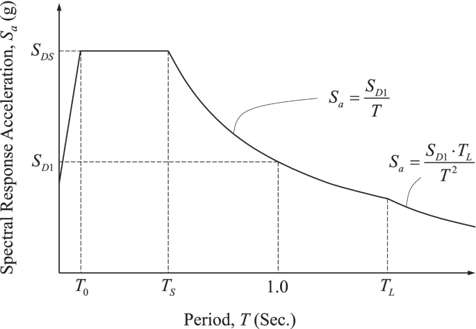
Typical design response spectrum (reproduced based on [ 13 ])
Seismic design requirements
The ASCE 7 Standard [ 11 ] provides the required seismic analysis and design procedures specifically related to building structures. The Standard states that a mathematical model shall be constructed and evaluated for a structure to demonstrate that it is capable of resisting the internal forces and deformations that will result from the applied seismic design forces. Three types of seismic analysis procedures are presented in the Standard: i) Equivalent Lateral Force Analysis, ii) Modal Response Spectrum Analysis, and iii) Seismic Response History Procedures. With all three of these procedures, the structure is expected to behave inelastically, meaning that buckling, yielding, and permanent deformation of the structural components are expected during the design earthquake event. By allowing a certain level of damage and permanent deformation to occur in the structure, a significantly more economical building can be provided than if the structure were designed to remain entirely elastic and undamaged after the design earthquake event. A brief description of the Equivalent Lateral Force Analysis (ELF) and the Modal Response Spectrum Analysis (MRS) procedures are discussed here. A more detailed description of the Seismic Response History Procedure will be available in the next section.
The ELF method is the least rigorous of the three available methods, yet it offers sufficiently accurate results for most structures and is therefore very widely used. As previously stated, it is recognized that the seismic load is dynamic in nature and that the structure will behave inelastically under this applied seismic load. However, the ELF method utilizes two key idealizations that make the analysis much simpler: the dynamic load is converted to an equivalent static load, and the structure is assumed to behave linear elastically. The inelastic effects are accounted for through the use of a response modification factor, R , and a deflection amplification factor, C d . The previously calculated S DS and S D1 values are modified by the R factor and the seismic importance factor, I e , to obtain the seismic response coefficient, C s . A C s value represents the pseudo-acceleration of the structure and is expressed in terms of “percent gravity” units. The equations for C s given in ASCE 7 [ 11 ] are dependent upon the structure’s fundamental period and are as follows:
where T is the fundamental period of the building and T L is the long transition period. For structures located where S 1 is equal to or greater than 0.6g, C s shall not be less than
The seismic response coefficient is then multiplied by the effective seismic weight of the structure to obtain the seismic base shear, V :
where W is the effective seismic mass of the building. The total seismic base shear, V , is vertically distributed to each of the discrete levels of the structure by use of the following equations
where F x is the portion of the seismic base shear induced at Level x ; w x is the portion of the effective seismic mass ( W ) that is located at or assigned to Level x ; and h x is the height above the base to Level x . The vertical distribution factor C vx uses the idealization that 100% of the structure’s mass participates in the first mode or the natural mode. All of the higher modes of the structure are neglected and the structure is reduced to one single-degree-of-freedom system, which greatly simplifies the analysis. The structure is analyzed for the series of static lateral seismic forces applied at each level, and the individual structural members are designed for the resulting forces.
The MRS approach, similar to the ELF method, uses a linear elastic idealization to simplify the analysis. The same response modification factor, R , is employed to account for the actual inelastic behavior of the structure. Whereas the ELF procedure is only interested in the first mode of vibration, MRS requires a more rigorous analysis to determine several of the natural modes of vibration of the structure. For each direction under consideration, the analysis requires that a sufficient number of modes are obtained to account for a combined modal mass participation of at least 90% of the structure’s mass. After obtaining the number of required modes, the multi-degree-of-freedom structure is converted into a series of single-degree-of-freedom systems, each of which have a unique mode shape and period of vibration. Each of the single-degree-of-freedom systems is then separately analyzed to determine the story forces, member forces, and displacements due to the design seismic loads. It should be noted that, although the MRS procedure utilizes certain dynamic properties of the structure, it is not a full-blown dynamic analysis method. The MRS results handle only the magnitude of maximum acceleration for each of the modes. Neither the sign (positive or negative), nor the time at which this maximum acceleration occurs are known. For this reason, the individual modal responses cannot be recombined exactly since their maximum values occur at a different point in time. A statistical combination of the individual modes is instead used: the outcomes from the series of uncoupled analyses are then combined through either the square root sum of squares (SRSS) or complete quadratic equation (CQC) method to attain the response of the structure.
Seismic response history procedures
The Seismic Response History Procedures presented in ASCE 7 [ 11 ] consist of a full dynamic analysis of the structure, wherein the analytical model is subjected to a series of time-dependent ground motions. Although the use of simulated ground motions is permitted and appropriate in certain instances, the ground motions modeled in the analysis will often be from actual past seismic events recorded in the vicinity of the structure. Two subcategories exist within the Seismic Response History Procedures: the Linear Response History Procedure and the Nonlinear Response History Procedure. As is evident by their titles, the Linear Procedure utilizes the idealization that the structure will behave linear-elastically throughout the course of the dynamic seismic loading event. This is the same idealization that is made in both the ELF and the MRS procedures, and ultimately results in a much simpler and manageable analysis. This idealization can be made due to the Equal Displacement Approximation Theorem, which states that the displacement of a structure undergoing nonlinear deformation is nearly equal to the displacement of the same structure behaving linear elastically. The linear force-deformation curve can, therefore, be extrapolated out to determine an equivalent linear design force for any given deformation magnitude. Figure 2 depicts a graphical representation of the Equal Displacement Approximation Theorem concept. To the contrary, the Nonlinear Procedure assumes a nonlinear hysteretic response of the structure, which is in fact how it will behave when subjected to a real-life seismic event. The Nonlinear Procedure is obviously the more rigorous of the two analysis methods to implement; however, it should be expected to yield more accurate results because more of the actual characteristics of the structure are being captured in the mathematical model.
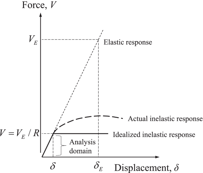
Equal Displacement Approximation Theorem (reproduced based on [ 13 ])
As mentioned earlier, the response history analysis is built upon a series of time-dependent ground motions as the loading parameters. Ideally, the ground motions that are selected will be analogous in nature to any future ground motions that the structure could be subjected to during an earthquake event. Therefore, the selected records should have magnitudes, fault distances, source mechanisms, and soil conditions that are all akin to what will be encountered at the project site [ 13 ]. The Pacific Earthquake Engineering Research Center (PEER) provides a large suite of past ground acceleration records that can be downloaded and implemented for a response history analysis [ 14 ]. Once a sufficient number (typically 3 to 7) of ground motions records have been selected for use in the analysis, each of the acceleration records is scaled. Scaling of the ground motions is necessary because although the type of ground motion in the record may be appropriate, it is likely that the magnitude of acceleration is either higher or lower than the acceleration that should be used for the structure being designed.
Developed from the procedures of ASCE 7 [ 11 ], the Design Response Spectrum is used as the benchmark for calculating the acceleration magnitude to which the more detailed time-dependent ground motions must be scaled. Specifically, each ground motion must be scaled so that the average of individual time-dependent spectra is not less than the demands stated in ASCE 7 [ 11 ]. The magnitude of acceleration is dependent on the natural period of the structure, so this requirement must be satisfied for the entire range of 20% to 150% of the natural period ( T ) of the structure under consideration. The 0.2 T lower bound of the range is meant to account for the higher modes of the structure, and the 1.5 T upper bound of the range is meant to account for inelastic response, which will likely have a higher period than the purely linear-elastic system. Owing to the complexity and certain subjective characteristics of the Seismic Response History Procedures, ASCE 7 [ 11 ] demands that a third-party design review be conducted on the seismic analysis and design if this procedure is implemented. The Standard states that the peer review must be documented by an independent team of registered design professionals who have demonstrated experience in the Response History Procedure. This is the only such strict requirement of a peer review found in ASCE 7 [ 11 ], which illustrates the complexity of the Seismic Response History Procedure.
Seismic retrofit of existing buildings
Modern building codes contain well defined seismic design parameters that, when properly applied, produce safe and predictable building performance during earthquakes. Seismic design provisions began making their way into building codes in the 1960s, though they were somewhat primitive and flawed in their infancy. Seismic analysis and design standards have progressively evolved over the past 40-plus years from research and industry knowledge, into what is currently in use today. Therefore, there are numerous buildings around the world that were designed and constructed prior to the enforcement of modern seismic design standards. These buildings pose a significant risk to their occupants in the event that a large earthquake should occur. Seismic retrofit is used as a means to upgrade these substandard buildings to reduce their risk of collapse and ensure the safety of their occupants.
Seismic retrofit background
The Long Beach earthquake of 1933 triggered the development of the first formal seismic building standards in the United States. Members of the California state legislature personally witnessed the collapse of buildings from the earthquake, and consequently enacted the Field Act of 1933. Through the Field Act, a statewide building code was developed with provisions to safeguard new buildings from earthquakes [ 15 ]. Although the Field Act was instrumental in providing seismic safety for newly built structures, it did not sufficiently address the considerable number of buildings constructed prior to its enactment. Recognizing this issue, the California legislature passed the Garrison Act in 1939 [ 15 ]. The Garrison Act specifically addressed California public school buildings that were built prior to 1933, requiring mandatory seismic evaluations of these structures. If the buildings were found to be substandard for seismic performance, they were required to be either retrofitted or abandoned.
Seismic design standards continued to develop at the state and local levels until the National Earthquake Hazards Reduction Program (NEHRP) was established by the U.S. Congress in 1977, with the intent “to reduce the risks of life and property from future earthquakes in the United States through the establishment and maintenance of an effective earthquake hazards reduction program.” The significance of NEHRP is that it brought the issues to the national level, providing a consistent and unified voice for earthquake risk mitigation in the United States. There are four primary Federal agencies that coordinate the activities of NEHRP and implement its programs: the Federal Emergency Management Agency (FEMA), the National Institute of Standards and Technology (NIST), the National Science Foundation (NSF), and the U.S. Geological Survey (USGS). The work of FEMA is of particular interest because the agency developed many of the fountainhead documents that lead to the current seismic design and rehabilitation provisions that are currently included in model building codes today. These include FEMA 547 ( Techniques for the Seismic Rehabilitation of Existing Buildings ) and FEMA P-750 ( NEHRP Recommended Seismic Provisions for New Buildings and Other Structures ), to name a few.
Seismic retrofit initiatives can generally be classified into two categories: mandatory programs and voluntary programs. Some local jurisdictions have implemented mandatory seismic retrofit programs for existing buildings that are deemed to be unsafe. These mandatory requirements are clearly meant to protect the safety of the public, but can come with serious political, economic, and societal side effects, and should therefore not be taken lightly. Voluntary seismic rehabilitation, carried out proactively by building owners without set requirements from the governing building jurisdiction, makes up a large percentage of retrofit projects. While motives that can drive a building owner to voluntarily retrofit their property vary widely, the most obvious one is to provide basic life safety to their occupants. Other motivations encompass protecting historic or landmark structures, minimizing disruptions and downtimes to their business, minimizing administrative efforts required to file insurance claims, and applying for disaster relief assistance. Regardless of what a particular building owner’s motive is to seismically retrofit an existing structure, there are numerous approaches for how it can be executed, which will be described in the succeeding section.
Common retrofit techniques currently in use
It is recognized that a plethora of seismic retrofit techniques are available, many of which have proven to be practical, economically viable, and effective through performance during actual earthquake events. Accordingly, a comparative review of these techniques currently in use is considered appropriate. Once a seismic deficiency is identified, there are different distinguishable classes of measures that can be taken to retrofit a building structure [ 16 ]:
Adding elements to increase strength or stiffness
Enhancing performance of existing elements by altering strength or deformation capacity
Improving connections between components
Reducing demand
Removing selected components from the lateral system
Increasing ductility
Adding new structural elements such as shear walls, braced frames, or moment frames is the most commonly used retrofit technique. The new elements are typically employed in combination with any existing lateral force resisting elements to create a new global strength and stiffness of the structure. When adding new structural elements, consideration must be given to the existing components such as diaphragms, chords, and collectors to ensure that they are capable of delivering the loads attracted by the newly introduced elements. Rather than adding new elements to the structure to improve its performance, the already existing elements of the lateral force-resisting system can be modified for upgraded performance. Examples of these methods include wrapping concrete columns with steel or composite materials to provide increased confinement and shear strength, and layering concrete and masonry shear walls with steel plates or composite materials to raise ductility and in-plane shear capacity. For this class of retrofit techniques, the vertical and horizontal distribution of seismic forces is not significantly changed because no new lateral elements are introduced to the seismic force resisting system.
Sometimes, the seismic evaluation process will reveal that the existing lateral force-resisting elements themselves have adequate strength and stiffness to resist the imposed earthquake forces, whereas the connections between these components are deficient. In these circumstances, retrofit techniques are available to improve the connections between components so that a complete load path exists and assumed force distributions can occur. This class of techniques can be classified as targeting load path deficiencies. Even if reducing the overall seismic demand is a technique that can be used when the structure contains a complete and well-connected seismic force-resisting system, it is weak relative to the design earthquake forces. One specific method within this class is lowering seismic mass, usually accomplished by removing one or more top floors, which in turn diminishes lateral load to the lower levels. This class of seismic demand reduction techniques also contains modification of dynamic response of the structure: most commonly through the use of localized damping devices or base isolation. The final class of retrofit techniques is removal of selected components from the structure. This is typically done to enhance the structure’s deformation capacity by uncoupling brittle elements from the lateral system. An example of this technique is introducing vertical sawcut joints in unreinforced masonry shear walls to change their failure mechanism from shear to a bending or rocking mode [ 16 ].
Seismic retrofit design process
The ASCE 41 document [ 17 ] is intended to be the single standard addressing the seismic performance of existing buildings. It was developed on the heels of two fountainhead guidelines: ATC-14: Evaluating the Seismic Resistance of Existing Buildings [ 18 ] and FEMA 273: NEHRP Guidelines for the Seismic Rehabilitation of Buildings [ 19 ]. Prior to these two documents, no formal standards were available for seismic evaluation and retrofit. Instead, design engineers were forced to use their individual judgment in analysis and design, usually attempting to apply standards meant for new buildings to evaluate and seismically retrofit constructed structures. Performance-based seismic design is the main approach of the provisions contained in ASCE 41 [ 17 ]. The concept of performance-based design and the specific parameters related to ASCE 41 [ 17 ] are described below.
Performance objective
The seismic design provisions of ASCE 7 [ 11 ] can generally be categorized as being prescriptive. That is, the criteria specify a minimum level of strength and stiffness of the structure, so little information is actually known about how the structure will perform during an earthquake event. For example, it is uncertain whether a building structure experiences substantial structural damage or remains fully operational with no damage. The ASCE 41 document [ 17 ], on the other hand, utilizes a performance-based approach to seismic design. This design philosophy explicitly appraises a structure’s anticipated performance for a specific seismic event it is likely to experience. Since more insight is gained regarding the building’s actual performance, the seismic force resisting system can either be made more economical while still meeting minimum performance standards, or higher levels of performance can be confirmed beyond what is assumed using the code-based prescriptive methods. Four separate sets of performance objectives are contained in ASCE 41 [ 17 ], which can be used for the seismic analysis and design of existing buildings: i) Basic Performance Objective for Existing Buildings, ii) Enhanced Performance Objectives, iii) Limited Performance Objectives, and iv) Basic Performance Objective Equivalent to New Building Standards.
The engineer, owner, building official, or a combination of the three determine which of the four performance objectives will be utilized based on the acceptable level of seismic hazard for the particular building in question. For instance, some buildings may be required to remain fully operational after a seismic event; by contrast, other buildings may allow a substantial amount of structural damage to be acceptable, only requiring total collapse prevention, so that building occupants can safely exit the structure after a seismic event. Specific factors that are used to quantify the performance criteria listed above include the post-yield ductility of the structure, the post-yield residual strength of the structure, and the failure type of the structure. Generally, a structure is considered to be seismically superior if it can withstand large plastic deformations beyond the displacement at which it first begins to yield, and it can exhibit a post-yield ultimate strength that is substantially greater than the magnitude of the initial yield strength. Figure 3 depicts examples of various nonlinear static force-deformation curves, revealing both good and poor post-yield seismic characteristics. Likewise, the degree of hysteretic behavior displayed by the structure’s lateral force resisting system is considered when quantifying its seismic performance. Ductile hysteresis loops, as shown in Fig. 4 (a), are desired since seismic loading is cyclical by nature, with the structure likely undergoing many reversible cycles of plastic deformation during an earthquake event. A pinched hysteresis loop (Fig. 4 (b)) performs poorly during a seismic event on account of its inability to undergo large post-yielding deformations and dissipate the kinematic energy within the structure from the dynamically applied load. The ductility and post-elastic characteristics of various structural materials and bracing configurations are of interest in practice.
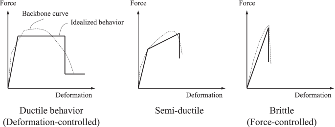
Various nonlinear force-deformation curves (reproduced based on [ 20 ])
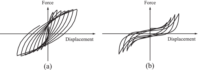
Cyclic force-displacement curves: a ductile hysteresis loops; b pinched hysteresis loops
Case studies
Delineated below are retrofit schemes illustrating the increased performance of buildings that are non-conforming to present seismic specifications. Both laboratory testing and numerical modeling are exemplified to support the effectiveness of strengthening techniques, followed by step-by-step implementations in the field.
On November 15, 2017, a record-breaking earthquake with a magnitude of 5.4 occurred in the Korean peninsula. Because the region was categorized into a low/moderate seismic hazard zone [ 21 ], seismic detailing was not part of ordinary practices. As a result, serious damage took place in many buildings, particularly for those that were constructed before 2000. The natural disaster brought about more than 80 injuries and thousands of evacuees, including economic losses of 48 million US dollars [ 22 ]. Shown in Fig. 5 are representative instances displaying the archetypal damage of vertical members in a seismically deficient school building. On most occasions, the structural system of public schools was composed of reinforced concrete frames with in-filled masonry walls that raised the stiffness and strength by restraining the deformation of adjacent columns. Although the use of these moment frames was beneficial, partially filled locations owing to architectural reasons (e.g., windows) were weak spots from a load-bearing perspective. In compliance with a post-earthquake evaluation report, decisions were made to demolish one building for the safety of occupants and dozens of buildings necessitated rehabilitation. The municipal authorities were eager to identify effective solutions at affordable cost.

Seismic damage of existing building: a plan view; b spalled concrete from columns
Retrofit methods
Among the assorted techniques discussed in a preceding section, two methods were adopted to ameliorate the seismic performance of aged school buildings: i) placing steel frames and ii) installing viscos dampers. These system-level approaches saved labor and material expenses relative to their member-level counterpart (i.e., strengthening each of the structural elements). As far as application is concerned, a few technical facets deserved attention. In other words, when mounting steel frames, integrity was of importance between the newly positioned and existing frames in order to take full advantage of the retrofit against external excitation forces. Similarly, proper interactions of the dampers with the reinforced concrete members were instrumental in alleviating hysteretic energy during an earthquake. To examine these compelling subjects, experimental investigations were necessary.
Implementation
Steel frame, laboratory testing.
As shown in Fig. 6 (a), two-story reinforced concrete frames were cyclically loaded with and without steel frames. Details about the test program are available in Lee et al. [ 23 ]. Contrary to the unstrengthened frame suffering localized cracks at beam-column joints (Fig. 6 (b)), the strengthened frame revealed less cracking and distributed cracks in the upper and lower stories, respectively (Fig. 6 (c)). In addition, the integrity between the steel and concrete frames was well preserved without premature failure.
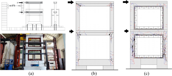
Laboratory testing of a two-story frame: a setup; b failure without steel frames; c failure with steel frames
Finite element modeling
Push-over analysis was conducted to assess the efficaciousness of the frame-based retrofit method. The modeled building was part of Onjung Middle School (Fig. 7 (a)), which was opened to students in 1994. The three-story structure was built with reinforced concrete frames comprising beams (300 mm by 600 mm) and columns (350 mm by 450 mm and 350 mm by 600 mm). Considering the categories specified in FEMA 356: Life Safety (LS) and Collapse Prevention (CP), equivalent to the 475-year and 975-year return periods, respectively [ 24 ], steel-braced frames were positioned at selected locations (Fig. 7 (b)). After retrofitting, the maximum base shear was increased from 6,700 kN to 24,000 kN under 1.2 times the design spectral response acceleration ( S DS = 0.554 and S D1 = 0.233), accompanied by distributed plastic hinges (Fig. 7 (c)). The spectral acceleration associated with the developed model is graphed in Fig. 7 (d).
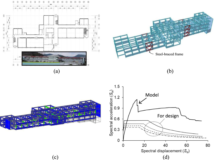
Push-over analysis of Onjung Middle School: a plan view; b developed model with steel-braced frames; c distribution of plastic hinges after retrofit; d response
Field application
Figure 8 pictures the step-by-step procedure of the foregoing approach. The existing masonry blocks were removed (Fig. 8 (a)) and in-situ material properties were measured using a non-destructive test device (Fig. 8 (b)). Subsequently, steel anchors were embedded to fix prefabricated steel frames (Figs. 8 (c) and (d), respectively). A set of the frames was assembled with hinges (Fig. 8 (e)) and the site work was completed with restored masonry and windows (Fig. 8 (f)). The purpose of situating the hinges (Fig. 9 (a)) was to control dimensional tolerance while conjoining the C-shape subcomponents. The implications of these hinges were studied by finite element models (Figs. 9 (b) and (c)) and, as plotted in Fig. 9 (d), insignificant differences were predicted with and without the hinges.
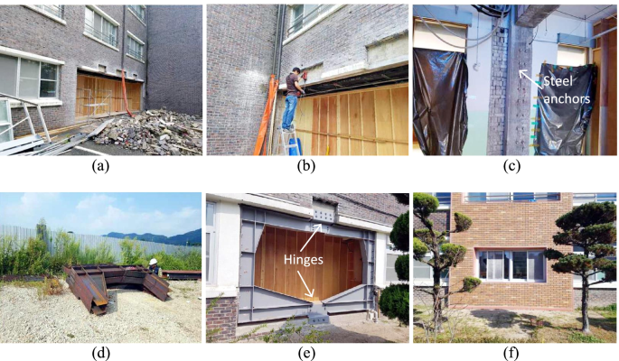
Implementation of seismic retrofit with steel frames (photo courtesy: SeongJin Engineering Group): a removal of existing masonry wall; b in-situ measurement of material properties; c installation of steel anchors; d delivered steel frame; e installed steel frame; f restoration of windows and masonry infills
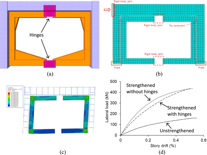
Modeling of installed steel frame: a schematic diagram; b finite element model; c stress contour; d load-story drift response
Viscos damper
The longevity of a damper was recorded when applying a sinusoidal displacement of 10 mm at 0.5 Hz (Fig. 10 (a)). Notwithstanding the marginal degradation of oscillation amplitudes during the early 3,000 cycles, resulting from a temperature change in the internal liquid, its ability to absorbing the applied energy was maintained over 10,000 cycles. Figure 10 (b) exhibits a two-story reinforced concrete frame retrofitted with a three-leg damper system. The frame, containing beams (350 mm by 500 mm) and columns (350 mm by 350 mm), was not damaged up to a drift ratio of 2.0%.
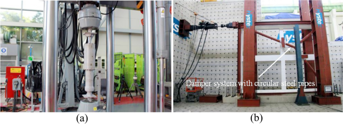
Viscous dampers as a retrofit element (photo courtesy: Dongyang Structural Safety Consultants Co.): a repeated loading up to 10,000 cycles; b structural testing
The damper system was employed to upgrade the seismic resistance of the 41-year-old Donghai Elementary School building (Fig. 11 (a)). Modal analysis was carried out to elucidate the dynamic characteristics and responses of the three-story framed structure (Fig. 11 (b)). As informed by model predictions, five damper systems were positioned to attenuate seismic energy (Fig. 11 (b)). The ramifications of the retrofit are given in Fig. 11 (d): the story drift ratio was considerably reduced across Floors 1 to 3.

Dynamic analysis of Donghai Elementary School: a plan view; b modal analysis; c placement of viscos dampers; d response
To accommodate the damper system, reinforced concrete foundations were prepared (Fig. 12 (a)). After setting up steel base plates (Fig. 12 (b)), a factory-made frame was erected and fixed to the building (Figs. 12 (c) and (d), respectively). The three-leg damper systems were then connected to the frame (Fig. 12 (e)) and painted to preclude the onset of corrosion (Fig. 12 (f)).
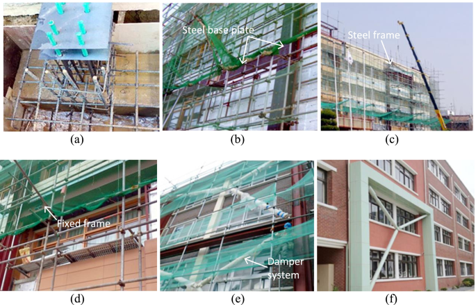
Implementation of seismic retrofit with viscous dampers (photo courtesy: San Engineering & Construction Architects and Techsquare Co.): a reinforcement of concrete foundation; b placement of steel plates; c lifting of steel frame; d installation of steel frame; e installation of damper; f completion
Concluding remarks
This paper has dealt with a comprehensive overview of seismic analysis, design, and retrofit for built-environments. The noticeable advances that have been made since the 1960s enabled the reliable operation and management of modern buildings under earthquake-induced distress. Complying with regulatory provisions stipulated in specifications and guidelines, practitioners furnish professional services to fulfill procedural requirements in a given situation, which are contingent upon predefined functionality, importance, and constraints. Oftentimes, approximate and conservative methods are preferred to simplify complex problems and to handle potential uncertainties in the field. Special attention should be paid to structures that were designed pursuant to outdated codes, especially for those possessing seismic deficiencies and thereby directly exposed to critical risks when subjected to unexpected ground motions. Unlike the case of newly constructed buildings, there may be unavoidable restraints in updating aged ones; as a consequence, project-specific settings are commonplace. Performance-based retrofit is a favorable alternative to conventional prescriptive approaches in the context of reflecting unique attributes, saving a construction and maintenance budget, and attempting tailored strategies. Rehabilitated members benefit from increased stiffness, strength, and deformability as well as from reduced external forces and accelerations by installing energy-absorbing systems. Regarding the selection of retrofit schemes, response spectra and hazard levels should be taken into account alongside anticipated failure modes. The case studies presented herein imparted simple yet adoptable technologies that can intensify seismic resistance of non-conforming buildings in a systematic manner, corroborated by laboratory testing and finite element modeling. Continued endeavors are indispensable to push forward the state of the art for the sake of achieving a sustainable society.
Availability of data and materials
The datasets used and/or analyzed during the current study are available from the corresponding author on reasonable request.
Kappos A, Penelis GG (2014) Earthquake resistant concrete structures. CRC Press, Boca Raton
Book Google Scholar
EPRI (2012) Seismic evaluation guidance: screening, prioritization and implementation details (SPID) for the resolution of Fukushima near-term task force recommendation 2.1: seismic, Electric Power Research Institute, Report No. 1025287, Palo Alto: Electric Power Research Institute.
Pohoryles, D.A. and Bournas, D.A. 2020. Seismic retrofit of infilled RC frames with textile reinforced mortars: State-of-the-art review and analytical modelling, Composites Part B, 183, 107702.
Fung JF, Sattar S, Butry DT, McCabe SL (2021) The total costs of seismic retrofits: state of the art, Earthquake Spectra, in-press. https://doi.org/10.1177/87552930211009522
Nigam, P.K. and Akhtar, S. 2021. Retrofitting practices in various categories of RCC structures: a comprehensive review, Materialstoday: Proceedings, 45(7), 7123-7131.
Attard TL, Abela CM, Dhiradhamvit K (2011) Seismic FRP retrofit of circular single-column bents using a ductility wrap envelope to alter failure modes. Eng Struct 33:1553–1564
Article Google Scholar
Lignos DG, Moreno DM, Billington SL (2014) Seismic retrofit of steel moment-resisting frames with high-performance fiber-reinforced concrete infill panels: large-scale hybrid simulation experiments. J Struct Eng 140(3):04013072
Zafar A, Andrawes B (2015) Seismic behavior of SMA-FRP reinforced concrete frames under sequential seismic hazard. Eng Struct 98:163–173
Caterino N, Nuzzo I, Ianniello A, Varchetta G, Cosenza E (2021) A BIM-based decision-making framework for optimal seismic retrofit of existing buildings. Eng Struct 242:112544
Gara F, Carbonari S, Roia D, Balducci A, Dezi L (2021) Seismic retrofit assessment of a school building through operational modal analysis and f.e. modeling. J Structural Eng 147(1):040220302
ASCE (2022) Minimum design loads and associated criteria for buildings and other structures (ASCE/SEI 7-22). American Society of Civil Engineers, Reston
Google Scholar
USGS (2022) Maps of earthquake shaking hazards. U.S. Geological Survey, Reston
FEMA (2009) Engineering guideline for incremental seismic rehabilitation (FEMA 420). Federal Emergency Management Agency, Washington, D.C.
PEER (2022) String ground motion databases. Pacific Earthquake Engineering Research Center, University of California, Berkeley
DGS (2002) Seismic safety inventory of California public schools, a report to the Governor of California and the California State Legislature. Department of General Services, Sacramento
FEMA (2006) Techniques for the Seismic Rehabilitation of Existing Buildings (FEMA 547). Federal Emergency Management Agency, Washington, D.C.
ASCE (2017) Seismic evaluation and retrofit of existing buildings (ASCE/SEI 41-17). American Society of Civil Engineers, Reston
ATC (1987) Evaluating the seismic resistance of existing buildings. Applied Technology Council, Redwood City
FEMA (1997) NEHRP Guidelines for the seismic rehabilitation of buildings (FEMA 273). Federal Emergency Management Agency, Washington, D.C.
FEMA (2005) Improvement of nonlinear static seismic analysis procedures (FEMA 440). Federal Emergency Management Agency, Washington, D.C.
Han S-W, Choi Y-S (2008) Seismic hazard analysis in low and moderate seismic region-Korean peninsula. Structural Safety 30(6):543–558
KMIS (2017) Pohang earthquake white paper: from the occurrence of the Pohang earthquake to the recovery, and the remaining tasks, Report No. 2018. 11-1741000-000123-01. Korean Ministry of Interior and Safety, Sejong
Lee H-J, Lee H-B, Park H-G, Lee J-K (2021) Cyclic loading test for two-story RC moment frames retrofitted with internal steel frames. J Structural Eng 147(2):04020333
FEMA (2000) Prestandard and Commentary for the Seismic Rehabilitation of Buildings (FEMA 356). Federal Emergency Management Agency, Washington, D.C.
Download references
Acknowledgements
The authors gratefully acknowledge various industry partners that participated in the case studies.
Not applicable.
Author information
Authors and affiliations.
Department of Civil Engineering, University of Colorado Denver, Denver, CO, USA
Ju-Hyung Kim
Fortis Structural, LLC, Greenwood Village, CO, USA
Christopher J. Hessek
Yail J. Kim
Department of Architecture and Architectural Engineering, Seoul National University, Seoul, Korea
Hong-Gun Park
You can also search for this author in PubMed Google Scholar
Contributions
JHK and CJH drafted the manuscript; YJK conceived the scope and contents of the research and wrote the manuscript; and HGP supervised the project, supplied technical data, and reviewed the manuscript. The author(s) read and approved the final manuscript.
Corresponding author
Correspondence to Yail J. Kim .
Ethics declarations
Ethics approval and consent to participate, consent for publication, competing interests.
The authors declare that they have no competing interests.
Additional information
Publisher’s note.
Springer Nature remains neutral with regard to jurisdictional claims in published maps and institutional affiliations.
Rights and permissions
Open Access This article is licensed under a Creative Commons Attribution 4.0 International License, which permits use, sharing, adaptation, distribution and reproduction in any medium or format, as long as you give appropriate credit to the original author(s) and the source, provide a link to the Creative Commons licence, and indicate if changes were made. The images or other third party material in this article are included in the article's Creative Commons licence, unless indicated otherwise in a credit line to the material. If material is not included in the article's Creative Commons licence and your intended use is not permitted by statutory regulation or exceeds the permitted use, you will need to obtain permission directly from the copyright holder. To view a copy of this licence, visit http://creativecommons.org/licenses/by/4.0/ .
Reprints and permissions
About this article
Cite this article.
Kim, JH., Hessek, C.J., Kim, Y.J. et al. Seismic analysis, design, and retrofit of built-environments: a procedural review of current practices and case studies. J Infrastruct Preserv Resil 3 , 11 (2022). https://doi.org/10.1186/s43065-022-00056-3
Download citation
Received : 15 June 2022
Accepted : 07 September 2022
Published : 20 September 2022
DOI : https://doi.org/10.1186/s43065-022-00056-3
Share this article
Anyone you share the following link with will be able to read this content:
Sorry, a shareable link is not currently available for this article.
Provided by the Springer Nature SharedIt content-sharing initiative
- Seismic analysis
- Strengthening

Earthquake Resistant Building : 10 Techniques Used by Architects Around the World

Falling under the category of natural disasters, the mere mention of earthquakes does not paint a very good picture. And rightfully so… the uprooting of families, the havoc within people, the loss of life, and the list goes on! However, in earlier times when the typology of structures was typically closer to the ground, not reaching a very substantial height, there would be scope to rush to open space for minimal damage. But in the present scenario with high-rise buildings jam-packed close to each other, there is left no option but to make the buildings strong enough to withstand the tectonic activities taking place in the region. The field of Engineering and Architecture is fortunately on a constant roll in devising newer technologies and implementations day by day for earthquake-resistant buildings that take us a step closer to a safer tomorrow for our inhabitants.
The following are the ten buildings that were designed for earthquake resistant buildings with specialized features to withstand the lashes of earthquakes:
1. Taipei 101, Taiwan | Earthquake Resistant Building
Architect: C.Y. Lee and Partners Year of completion: 2004
Standing 508 m tall, making it the 10 th tallest building in the world as of 2020, Taiwan’s giant has had to have gone through complex engineering and clever architectural planning that went into building this structure (construction began in 1998). The building uses the tuned mass damper (TMD) approach to counteract the swaying this structure may experience in events of an earthquake. There hangs a ‘ball of steel’ weighing 730 tonnes acting as a centralized pendulum that is designed to oscillate away from the lateral bend of the building to neutralize the effect of the earthquake. Despite having such a dense and heavy profile, it manages to appear intricate and aesthetic to a viewer.

2. Utah State Capitol building, USA
Architect: Richard K. A. Kletting Year of completion: 1916 (with later seismic upgrades in 2004)
This neoclassical Corinthian-styled classic colonnaded façade of a structure resembles the strength and repose a government building was once intended to. However, there were quite a few later innovations that were introduced to the structure’s foundation to deal with the earthquake situation in the region. It was designed to withstand up to 7.3 magnitude earthquakes while keeping the classical aura of the building intact. This base isolation system bears 281 lead-rubber laminated base isolators attached to the building foundation with the help of steel plates. In the event of an earthquake, every hard impact is absorbed by the rubber isolators while also gently shaking the building back and forth, so there is no damage or collapse.

3. Petronas Twin Tower, Malaysia
Architect: César Pelli Year of completion: 1999
This iconic structure remained the tallest skyscraper in the world well until the year 2004. This still, however, remains the tallest twin tower in the world at a whopping height of 452m. The two glass towers are connected with a centralized 2 storey bridge. This feature is not only aesthetic addition but also is designed to slide in and out of the building every time there seem to be substantial lateral loads acting upon the building.

4. Burj Khalifa, Dubai | Earthquake Resistant Building
Architect(s): Skidmore, Owings, and Merrill Year of completion: 2010

The world’s tallest building, the Burj Khalifa Bin Zayed, is an architectural marvel standing tall and safe. All thanks to its advanced architectural and structural system designed to withstand earthquakes ranging from 5.5 to 7.0 magnitude on the Richter scale. It is equipped with a mass dampener/harmonic absorber within the structure to absorb the vibrations. The minaret-inspired building was once introduced to some tremors due to the Iran earthquake in 2008, but the structure remained unharmed and intact.


5. The Yokohama Landmark Tower
Architect: Hugh Stubbins Year of completion: 1993
The beauty of technological advancements is that it eventually makes up for the human errors that were made in the past (well, for the most part). Similarly, as we humans occupied and inhabited the geologically active island chains, regions like Japan are at a high risk of an earthquake. The buildings actively respond to the same very efficiently as well… the Yokohama Landmark Tower is no exception. This building equips within itself a Hybrid mass damper (a combination of tuned mass damper and an active control actuator) as well as something called “bandage pillars”. These are earthquake resisting pillars that are designed with the help of resin fibres that essentially may allow some chunks of the pillar to fall off but prevent it from collapsing in case of an earthquake.

6. Citigroup Center
Architect: Hugh Stubbins Year of completion: 1976
What makes this building a rather unique addition to the New York skyline is the 410-ton concrete tuned mass damper added much later into the structure. It was the first building in New York to equip the same… the initial structure was provided with much weaker bolded joints, making it a structurally unsound and hazardous building as the lateral loads were said to be too much load on them.

7. U.S Bank Tower, USA
Architect: Henry N. Cobb Year of completion: 1989
Situated in the seismically active area of Los Angeles, this is the second tallest skyscraper in an earthquake-prone zone following Taipei 101. This structure is designed in a way that it can withstand an earthquake of up to 8.3 magnitudes on the Richter scale.

8. One Rincon Hill South Tower, USA
Architect: John C. Lahey Year of completion: 2008
The rather unique feature about this high-end residential tower is the tuned liquid mass damper atop the 60 storey structure. It is essentially a 5 feet tall tank filled with 50,000 gallons of water that flows the opposite side of the sway to decrease the impact on the inhabitants.

9. Sabiha Gökçen International Airport, Turkey
Architect: HEAŞ (Airport Management & Aeronautical Industries Inc)
The confluence of three major tectonic plates in the City of Istanbul makes it a major earthquake-prone area. Resultant of which came the Sabiha Gökçen International Airport. With the ability to withstand an earthquake up to the magnitude of 8 on the Richter scale. The computer-simulated triple friction pendulum isolators help the structure not only stay aloft in the event of an earthquake but also start functioning right after the passing of the same.

10. The Transamerica Pyramid, USA | Earthquake Resistant Building
Architect: William Pereira Year of completion: 1972
This San Francisco high rise was designed in such a way that it reflects some sunlight to its neighbors, considering the tiny heights of the buildings around. Along with those features, it also is very efficient in terms of earthquake resistance. The building is said to rest on a steel and concrete foundation that is engineered to move along with the earthquake giving subtle sways to the structure itself. The tower survived a 7.1 magnitude earthquake in 1989.

In this never-ending road down the structural lane, there will always be a constant need to keep improving and experimenting to adapt and survive against natural calamities while experiencing minimal damage to property, as well as life. We may not have figured everything against saving one’s structure completely against the mighty quake, but we are surely in a hopeful place.

While establishing the co relation of romanticism with words and architecture, Mohammed Bilal Shariff aims to use RTF as a medium to put forth a piece of his mindset with a desire to ignite new thoughts and perspectives in the reader's mind.

10 Plants to use in Landscape Architecture and why

Fumikhiko Maki designs Toilet with the curved roof ‘Squid Toilet’
Related posts.

Evolving Perspectives: A Journey Through Architecture Education

Luxury Housing and Sustainable Materials

The Interplay of Form and Function: Exploring Artistic Elements in Architectural Design

Architecture of the Ancient Roman Baths

Building Connections: The Integral Role of Architecture in Human Existence and Community

Visionary Horizons: A Girl’s Journey through the Future of Architecture in 2060
- Architectural Community
- Architectural Facts
- RTF Architectural Reviews
- Architectural styles
- City and Architecture
- Fun & Architecture
- History of Architecture
- Design Studio Portfolios
- Designing for typologies
- RTF Design Inspiration
- Architecture News
- Career Advice
- Case Studies
- Construction & Materials
- Covid and Architecture
- Interior Design
- Know Your Architects
- Landscape Architecture
- Materials & Construction
- Product Design
- RTF Fresh Perspectives
- Sustainable Architecture
- Top Architects
- Travel and Architecture
- Rethinking The Future Awards 2022
- RTF Awards 2021 | Results
- GADA 2021 | Results
- RTF Awards 2020 | Results
- ACD Awards 2020 | Results
- GADA 2019 | Results
- ACD Awards 2018 | Results
- GADA 2018 | Results
- RTF Awards 2017 | Results
- RTF Sustainability Awards 2017 | Results
- RTF Sustainability Awards 2016 | Results
- RTF Sustainability Awards 2015 | Results
- RTF Awards 2014 | Results
- RTF Architectural Visualization Competition 2020 – Results
- Architectural Photography Competition 2020 – Results
- Designer’s Days of Quarantine Contest – Results
- Urban Sketching Competition May 2020 – Results
- RTF Essay Writing Competition April 2020 – Results
- Architectural Photography Competition 2019 – Finalists
- The Ultimate Thesis Guide
- Introduction to Landscape Architecture
- Perfect Guide to Architecting Your Career
- How to Design Architecture Portfolio
- How to Design Streets
- Introduction to Urban Design
- Introduction to Product Design
- Complete Guide to Dissertation Writing
- Introduction to Skyscraper Design
- Educational
- Hospitality
- Institutional
- Office Buildings
- Public Building
- Residential
- Sports & Recreation
- Temporary Structure
- Commercial Interior Design
- Corporate Interior Design
- Healthcare Interior Design
- Hospitality Interior Design
- Residential Interior Design
- Sustainability
- Transportation
- Urban Design
- Host your Course with RTF
- Architectural Writing Training Programme | WFH
- Editorial Internship | In-office
- Graphic Design Internship
- Research Internship | WFH
- Research Internship | New Delhi
- RTF | About RTF
- Submit Your Story
Looking for Job/ Internship?
Rtf will connect you with right design studios.

Join TheConstructor to ask questions, answer questions, write articles, and connect with other people. When you join you get additional benefits.
Confirm Password *
First Name *
Last Name *
Country Select a country… Åland Islands Afghanistan Albania Algeria Andorra Angola Anguilla Antarctica Antigua and Barbuda Argentina Armenia Aruba Australia Austria Azerbaijan Bahamas Bahrain Bangladesh Barbados Belarus Belau Belgium Belize Benin Bermuda Bhutan Bolivia Bonaire, Saint Eustatius and Saba Bosnia and Herzegovina Botswana Bouvet Island Brazil British Indian Ocean Territory British Virgin Islands Brunei Bulgaria Burkina Faso Burundi Cambodia Cameroon Canada Cape Verde Cayman Islands Central African Republic Chad Chile China Christmas Island Cocos (Keeling) Islands Colombia Comoros Congo (Brazzaville) Congo (Kinshasa) Cook Islands Costa Rica Croatia Cuba CuraÇao Cyprus Czech Republic Denmark Djibouti Dominica Dominican Republic Ecuador Egypt El Salvador Equatorial Guinea Eritrea Estonia Ethiopia Falkland Islands Faroe Islands Fiji Finland France French Guiana French Polynesia French Southern Territories Gabon Gambia Georgia Germany Ghana Gibraltar Greece Greenland Grenada Guadeloupe Guatemala Guernsey Guinea Guinea-Bissau Guyana Haiti Heard Island and McDonald Islands Honduras Hong Kong Hungary Iceland India Indonesia Iran Iraq Isle of Man Israel Italy Ivory Coast Jamaica Japan Jersey Jordan Kazakhstan Kenya Kiribati Kuwait Kyrgyzstan Laos Latvia Lebanon Lesotho Liberia Libya Liechtenstein Lithuania Luxembourg Macao S.A.R., China Macedonia Madagascar Malawi Malaysia Maldives Mali Malta Marshall Islands Martinique Mauritania Mauritius Mayotte Mexico Micronesia Moldova Monaco Mongolia Montenegro Montserrat Morocco Mozambique Myanmar Namibia Nauru Nepal Netherlands Netherlands Antilles New Caledonia New Zealand Nicaragua Niger Nigeria Niue Norfolk Island North Korea Norway Oman Pakistan Palestinian Territory Panama Papua New Guinea Paraguay Peru Philippines Pitcairn Poland Portugal Qatar Republic of Ireland Reunion Romania Russia Rwanda São Tomé and Príncipe Saint Barthélemy Saint Helena Saint Kitts and Nevis Saint Lucia Saint Martin (Dutch part) Saint Martin (French part) Saint Pierre and Miquelon Saint Vincent and the Grenadines San Marino Saudi Arabia Senegal Serbia Seychelles Sierra Leone Singapore Slovakia Slovenia Solomon Islands Somalia South Africa South Georgia/Sandwich Islands South Korea South Sudan Spain Sri Lanka Sudan Suriname Svalbard and Jan Mayen Swaziland Sweden Switzerland Syria Taiwan Tajikistan Tanzania Thailand Timor-Leste Togo Tokelau Tonga Trinidad and Tobago Tunisia Turkey Turkmenistan Turks and Caicos Islands Tuvalu Uganda Ukraine United Arab Emirates United Kingdom (UK) United States (US) Uruguay Uzbekistan Vanuatu Vatican Venezuela Vietnam Wallis and Futuna Western Sahara Western Samoa Yemen Zambia Zimbabwe
By registering, you agree to the Terms of Service and Privacy Policy . *
Log in to TheConstructor to ask questions, answer people’s questions, write articles & connect with other people. When you join you get additional benefits.
Join for free or log in to continue reading...
Username or email *
Forgot Password
Lost your password? Please enter your email address. You will receive a link and will create a new password via email.
Sorry, you do not have permission to ask a question, You must log in to ask a question. Join now!

The Constructor
Earthquake resistant design techniques for buildings and structures.
Do you need to remove the ads? Join now!
🕑 Reading time: 1 minute
- Base Isolation
Energy Dissipation Devices
Base isolation method.
Figure 1: Base-Isolated and Fixed-Base Buildings
Earthquake Generated Forces
Figure 2: Base-Isolated, Fixed-Base Buildings
Deformation and Damages to Structures
Response of base isolated building.
- Friction Dampers : these utilize frictional forces to dissipate energy
- Metallic Dampers : utilize the deformation of metal elements within the damper
- Viscoelastic Dampers : utilize the controlled shearing of solids
- Viscous Dampers : utilized the forced movement (orificing) of fluids within the damper
Fluid Viscous Dampers
Damping devices and bracing systems.
Figure 3: Damping Device Installed with Brace
Padmanabhan G
Related posts.

Factors Influencing Earthquake Resistant Design of Structures

Guidelines for Earthquake Resistant Design of Structures
- Reference Manager
- Simple TEXT file
People also looked at
Original research article, seismic isolation for protecting historical buildings: a case study.

- 1 Department of European and Mediterranean Cultures (Architecture, Environment and Cultural Heritage), University of Basilicata, Matera, Italy
- 2 Department of Structural and Geotechnical Engineering, Sapienza University of Rome, Rome, Italy
The protection of cultural heritage from seismic risk is an open issue due to the difficulties in finding technical solutions allowing a balance between their effectiveness and invasiveness. Among the available protection techniques, seismic isolation is one of the most suitable obtaining a significant performance improvement by acting on a limited portion of the structure. In this paper, it is shown an application of such technique on a reinforced concrete frame building cataloged as of historical interest by Italian Ministry of Cultural Heritage. It was realized in 30's representing the “Modern Style” of Italian Architecture, also known as Italian Rationalism, and designed only for vertical loads without any specific regulation for lateral loads. Geometry, material properties and reinforcements characteristics have been derived from an extensive investigation campaign. By the means of a FEM 3D model they are simulated among them the seismic responses of both existing and retrofitted building through a seismic isolation system composed by elastomeric and sliding isolators. Furthermore, a new methodology for estimating the seismic capacity exhibited by the structure in the past is presented and applied.
Introduction
To date, the strategy of seismic isolation as earthquake-resistant technique applied on existing buildings is become very common all over the World. It is based on the concept of lengthening the natural period of the structure from the predominant frequency of the ground motions, significantly reducing the transmitted acceleration to the superstructure ( Kelly, 1986 ; Alhan and Gavin, 2004 ; Ibrahim, 2008 ). The isolation plane is generally realized above the foundation and it consists of devices capable of reducing the lateral stiffness of the superstructure combing re-centering and energy dissipation action. In this way, the seismic demand on the superstructure is drastically reduced and the performance requirements are satisfied by strongly limiting or nullifying the elements damage. In addition, this strategy requires spaces of small dimensions to be realized, and in many cases not even requiring the evacuation of the occupants.
In Italy, during the last 30 years, the seismic isolation applications have been increased more and more representing, nowadays, a common technique of structural design. A proof of this is given by the fact that the Italian Design Code ( NTC, 2008 ) and its recent update ( NTC, 2018 ) recognize the seismic isolation as standard application in buildings design. First applications of this strategy may be found in Mokha et al. (1996) , Martelli and Forni (1998) , Kawamura et al. (2000) , Luca et al. (2001) , Kelly (2002) , Braga et al. (2005) , Tomazevic et al. (2009) , and Lignola et al. (2016) .
Commonly, seismic isolation is used for retrofitting of Reinforced Concrete (RC) existing buildings, since very often they were designed only for vertical loads without any detailing rule for ductility, as highlighted in some recent studies such as, among the others, ( Laterza et al., 2017a ). In these cases, the seismic isolation is preferred to widespread and more invasive local interventions, consisting in strengthening and improving the confinement of the elements ( Braga et al., 2006 ; D'Amato et al., 2012a , b ; Laterza et al., 2017b ; Caprili et al., 2018 ; Faqeer et al., 2018 ), or consisting in adding new structural elements in order to carry the seismic loads and dissipate energy ( Ciampi et al., 1995 ; Di Sarno and Manfredi, 2010 , 2012 ; Mazza and Vulcano, 2014 ; Laguardia et al., 2017 ; Braga et al., 2019 ).
This paper presents the application of the seismic base isolation for retrofitting an existing RC building, in accordance to the Italian Design Code ( NTC, 2008 ). The case study chosen is the public building named “ Archivio di Stato ” (State Archive) designed and built during the 30's in Potenza, a city located along the Apennine chain with the highest seismic hazard in Italy. Moreover, due to its architectural importance, the considered building is protected by the Italian Ministry of Cultural Heritage. Indeed, it is representative of the “Modern Style” of Italian Architecture, also known as Italian Rationalism. The numerical simulations are obtained through response spectrum analyses for Fixed-Base (FB) and Base-Isolated (BI) model, considering also the impact of the variability of the friction coefficient of sliding devices.
In this article, it is therefore highlighted the effectiveness of the isolating system in order to retrofit historical buildings. In the case analyzed, several local reinforcements are required to gain the assumed seismic performance level, given the need to reduce the invasiveness of the intervention, the number and the impact of these interventions by varying the retrofit strategy is discussed. Moreover, in this study it is proposed a new and simplified methodology to estimate the structural capacity on the basis of the seismic performances exhibited by the building in the past occurred earthquakes. Precisely, the estimation of the occurred seismic action at building base stems from ground motions (GMs) available and recorded in the site surrounding area. The main idea of the proposed simplified methodology is the following: if a fixed base-building has experienced an earthquake in the past with negligible or limited damages, the seismic intensity of that earthquake may be intended as an experimental proof related to the building capacity, or rather, to the capacity of the superstructure portion of the base-isolated building. The new methodology can be used as a fast and useful tool to roughly assess the seismic performances of buildings sample in a certain area, identifying the most suitable ones for a seismic isolation strategy, implying negligible or limited damages of the superstructure. The so-estimated seismic capacity can be also used as an experimental threshold to be considered in validating implemented numerical models for seismic assessment of a structure.
Case Study—“Archivio di Stato” of Potenza, Italy (1930)
The “ Archivio di Stato ” (State Archive) was designed and realized in the 30's by the architect Ernesto Puppo (1904–1987), one of the principal exponents of Italian Rationalism Movement. It is located in the city of Potenza along a hillside on a steep slope toward the City center and used as State Archive. The building consists of RC frame structures composing three intersecting volumes with a markedly non-symmetric geometry. In Figure 1 are shown some views and technical drawings of the considered buildings. In particular, in Figure 1A they are reported a transversal and a longitudinal section of the building, where it can be appreciated the hillside disposition and the relevant irregularity in elevation. The Italian Ministry of Cultural Heritage has recently added this building among those to be protected due to its architectural relevance, even considering the construction period and the urban context in which it is inserted, that can be appreciated in the photos of Figure 1B . Figure 1C shows the current abandonment state of the building due to the slight damages suffered during the Irpinia earthquake on 23/11/1980, after that it was closed.
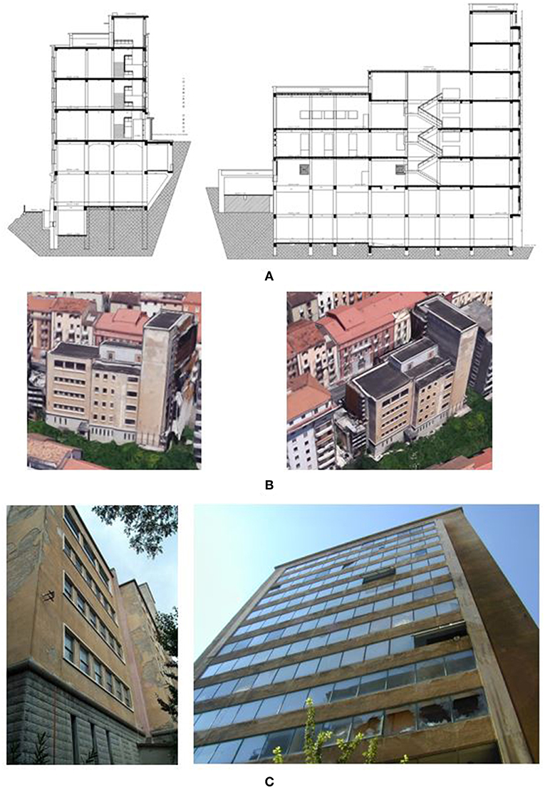
Figure 1 . Some images of the considered case study. (A) Transversal and longitudinal section of the building, (B) images from Google Maps (2019) , and (C) current conditions of the building.
This building is of considerable importance also because it was one of the first realized in Italy with RC frame-resisting structure by the “ Cooperativa Muratori e Cementisti di Ravenna” construction company between 1936 and 1939. The frame structure is characterized by columns with square or rectangular sections with deep or flat beams, the floors slabs are made of reinforced concrete with predominant unidirectional warping. The building has three underground floors and six floors above ground with an average interstory height of about 4.5 m. Due to the strong architectural variations in height, the floors surfaces significantly vary with height. Table 1 summarizes these geometrical details, where the Level 0 corresponds to the floor accessible from the main street facing the building. Moreover, each column is founded on a deep well-foundation and connected by a beam gridwork placed at a height of −9.6 m, while no connection is present for the columns of the lower part of the building, founded at −13.80 m. Finally, infills are made of bricks and placed both in the external frames and in some internal frames.
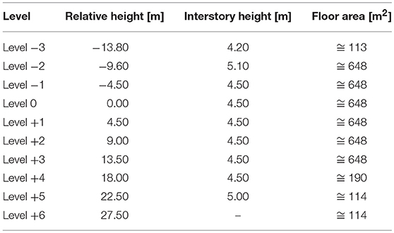
Table 1 . Floor surfaces, plan and interstory heights of the “Archivio di Stato” building.
Materials Properties and Concrete Elements Details
In order to characterize this building, in addition to an in-depth geometrical investigation, it has been also necessary to perform an extensive investigation campaign on material properties and structural reinforcement detailing disposition. To this regard, it should be noted that, at the time of construction, there were few code indications for reinforced concrete constructions or available consolidated calculation schemes. Therefore, the survey campaign has played an important role to define the structural characteristics of the case study. Totally, the investigations campaign consisted of sampling of 13 reinforcing steel bars specimens, 21 concrete core drilled, 62 SONREB tests, and over 300 sections pacometric investigations for construction details. In this study, since the elaboration data is still in progress, only the results of the material properties measured with laboratory tests on concrete and rebars samples are illustrated. More in detail, laboratory tests on concrete samples ( Figure 2B ) extracted from beams and columns were performed to evaluate the compressive strength of concrete. The mean values of compressive strength (f cm ) and the coefficient of variation (CV) of the sample are reported in Figure 2A . Since a different homogeneity along the building height was observed, the measured compressive strengths were divided in two different groups ( Figure 2A ): Group 1 from height of −9.6–0.0 m, having an average value of 24.2 MPa measured on n. 11 concrete core samples; and Group 2 , having a compressive strength of 18.8 MPa, from floor having 4.5 m height up to the roof. The so obtained compressive strengths, given the height differentiation, have been used for both beams and columns.
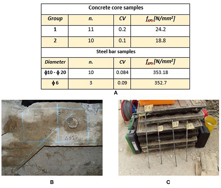
Figure 2 . Investigation campaign: (A) Material properties derived from extracted samples. N, number of samples; CV, coefficient of variation; f cm , average compressive strength; f ym , average tensile strength; (B) steel reinforcements disposition obtained through pacometric investigations and sampling of concrete specimen, (C) steel samples collected.
As regards the steel reinforcements, in situ investigations showed that, according to the RC existing buildings realized in 30's, only smooth bars were applied. A total of 13 samples were extracted ( Figure 2C ), 3 from hoops of 6 mm diameter, and 15 from longitudinal bars having a diameter between 8 and 16 mm. Figure 2A reports also the average tensile strength of the steel samples measured with laboratory tests. The values are separately reported for longitudinal bars and for hoops. The obtained average values are compatible with the Steel strength class Aq 42, very common in the construction period of the building ( Verderame et al., 2001 ).
Construction details of beams and columns were measured with in situ pacometric measurements and visual inspections of reinforcements by locally removing the concrete cover. A simulated design in accordance with the design practice of that period was also performed in order to compare the obtained results with those measured through the experimental campaign. Since a good agreement was obtained, the simulated design was extended to all RC elements of the building. More in detail, 2.5 and 6 kN/m 2 were used as variable loads acting at the different floors for designing the reinforcements of decks and beams in according to simple schemes of continuous beams, as usual in the design practice. On the contrary, for columns no specific design scheme was adopted, since they were designed only for vertical loads without any lateral action for taking into account the earthquake effects. Therefore, it has been reasonable to design longitudinal and transverse reinforcements by assuming the detailing rules provided in the Italian Royal Decree ( R.D., 1939 ), that is the design code temporally closer to the years of construction of the building. In particular, it gave the provision of assigning to RC columns an amount of longitudinal bars equal to 0.8% of A c if A c < 2,000 cm 2 , and equal to 0.5% of A c if A c > 5,000 cm 2 , where A c is the column gross area. Between A c = 2,000 cm 2 and A c = 5,000 cm 2 a linear interpolation was allowed. As for the hoops, on the basis of the obtained measurements with the pacometric tests, the spacing has been considered equal to 25 cm, slightly higher than the minimum requirements of R.D. (1939) . For completeness sake, Figure 3 illustrates the reinforcement details obtained for some columns and beams.
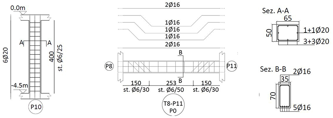
Figure 3 . Typical reinforcement details of columns and beams.
Numerical Models
Figure 4A depicts the FEM model implemented in SAP 2000 software ( Computers Structures Inc, 2015 ) for the numerical simulations of the existing building fully fixed at the base. Specifically, beams and columns have been modeled using linear elastic frames, while the decks have been modeled with shell elements having orthotropic stiffness to consider the actual heights, while the soil pressure of the underground building portions have been neglected. Finally, in order to take account of the section cracking occurring during the seismic excitation, the flexural and shear stiffness of primary columns and beams have been both reduced of 50%, in accordance with the maximum cracking level allowed by the Italian code ( NTC, 2008 ).
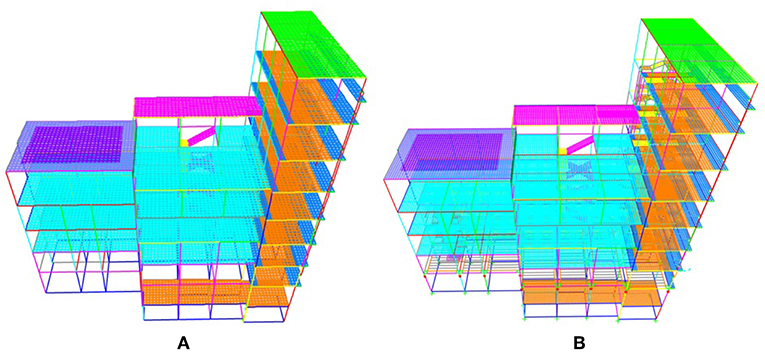
Figure 4 . 3D views of the implemented FEM model for fixed-base structure (A) and for base-isolated structure (B) .
In Figure 4B the base-isolated model is reported. The added elements, such as the rigid steel deck placed above the devices and the others beams, have been modeled also with linear elastic frames. The isolating system, as illustrated and detailed later in Figure 9 , is composed by elastomeric and friction isolators, both modeled as linear link elements, whose stiffness corresponds to the secant one at the design displacement for the considered design limit state.
Site Seismic Hazard and Response Spectra
The site seismic hazard and response spectra considered in the numerical simulations are shown in Figure 5 . Precisely, Figure 5A reports the parameters defining the seismic action in terms of seismic spectra referred to a rigid soil ( Type A ) for each Limit State considered by the Italian design code ( NTC, 2008 ), that are: Operativity Limit State ( OLS ), Damage Limit State ( DLS ), Life-SafetyLimit State ( LSLS ), Collapse Limit State ( CLS ). The site seismic hazard is considered for a reference period of V R of 50 years (Nominal Life V N = 50 years and Coefficient of Use C U = 1), where: T R is the return period, a g is the maximum soil accelerations in the case of rock soil, F 0 is the maximum amplification of the spectrum, T c * is the transition period between constant acceleration and constant velocity part of the spectrum.
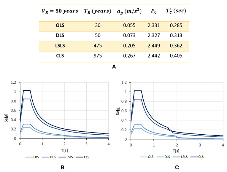
Figure 5 . Site seismic hazard and response spectra considered. (A) Parameters defining the seismic action referred to a rigid soil (Type A) for each limit state. (B) Elastic response spectra (ξ = 5%) for a soil Type C. (C) Design spectra for isolated system for a soil type C.
In Figure 5B are reported the elastic response spectra according to NTC (2008) for the case analyzed, by considering a ground of Type C and a conventional viscous damping ratio ξ = 5%. In order to perform linear analyses, the Italian code ( NTC, 2008 ) suggests to keep in count the energy dissipated by the isolating system using an appropriate design spectrum. This spectrum is obtained by reducing of a factor η = 10 ( 5 + ξ e s i ) the spectral ordinates with period higher than 0.8 * T is (that is the range of isolating system vibrations periods), where ξ esi is the equivalent viscous damping ratio of the isolating system for the design horizontal displacement. In accordance with this, Figure 5C reports the so-obtained design spectra, where the equivalent ξ esi for each limit state is numerically reported in Figure 9 .
Numerical Results
In this section are illustrated and commented the results obtained with the implemented FEM models where, as described in the previous section, linear elastic frames are used. In the case of base-isolated building, the seismic devices are modeled as linear links, where friction sliders have a linear stiffness corresponding to the secant one at the considered design limit state. In all the analyses performed, the horizontal seismic action effects are evaluated with a modal analysis with response spectra, where the modal effects are combined with CQC combination rule.
Seismic Response of Fixed-Base Building
The results of the modal analysis in the case of fixed-base building are reported in Figure 6 where, for brevity, are reported only the first three vibration modes. The figure illustrates the shape of each vibration mode, and reports the related vibration period T , the translational modal participating mass ratios along X and Y (U X and U Y ), and the rotational one around Z (R Z ). It is found that the first mode arises mainly along the X direction, that is the direction along which the structure is more flexible and exhibits a more regular response. On the contrary, the second and the third modes are both roto-translational, involving a coupling of a translation along Y and a rotation along Z .
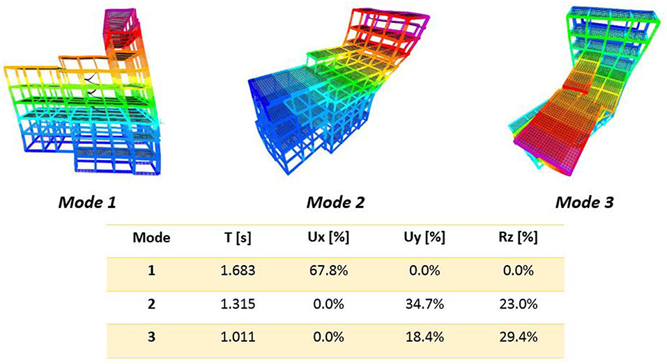
Figure 6 . Fixed-base model. Shapes and dynamic properties of the first three vibration modes.
It is interesting, for the purposes of this work, to compare the floor shear distribution over the building height as illustrated in Figure 7A , obtained by considering the seismic action acting for Life-Safety Limit State. Along both the directions the shear distribution is regular and linear as demonstrated by the high mass participation ratio of the first mode. Moreover, also a study of the shear distribution at a certain level may be done. For instance, in Figure 7B the shear distribution at Level 0 among the resistant frame is illustrated. As it is easy to note, the response is quite symmetric along the X direction, where the only two central vertical frames (having y = 8.5 m e y = 13.5 m) absorb more than 50% of the total shear at Level 0 . By contrast, along the Y direction a consistent irregularity in the response is observed. The two higher frames (x = 0 m e x = −6 m), representing the building tower, are stiffer, bearing a considerable amount of the floor shear. Besides the shear global distribution, in order to verify the performances for ultimate limit states, local checks of demand/capacity ratios for ductile and fragile mechanisms have been performed, according to the requirements of Italian design code ( NTC, 2008 ). By performing these checks, it emerges that about the 15% of beams and 2% of columns don't have enough flexural or shear capacity, by considering only gravity loads. Moreover, by considering the seismic loads, almost all the columns and the 30% of beams don't have enough shear capacity.
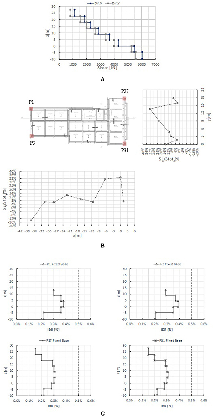
Figure 7 . Fixed-base model. Shear and drift distribution. (A) Shear distribution over the building height for Life-Safety Limit State, (B) shear distribution among the frames at Level 0 for Life-Safety Limit State, (C) drifts distribution over the building height in the y-direction for Damage Limit State.
Finally, in Figure 7C the floor drifts obtained by considering the expected horizontal seismic action for the Damage Limit State are also plotted. For brevity, in this study the maximum horizontal drifts distribution is illustrated, arising along only the Y direction. Again, as observed for the shear forces, the distribution is quite regular above the height of the building and in any case the maximum values don't exceed the 0.5%, that is the limit for damage limit state indicated by the ( NTC, 2008 ).
Seismic Response of Base-Isolated Building
The structural intervention of seismically isolating the super-structure allows a global retrofit and, simultaneously, the respect of the architectural constraints on the building, related to its historical interest. Basically, the design criterion was of reducing as much as possible the seismic action and the number of local reinforcements on the structural elements. The solution adopted is relatively easy to realize, given the fact that at a height of −4.5 m the building has an existing grid of RC beams completely free from constraints, below which the insertion of the isolation devices may be done. Then, a rigid deck may be realized above the isolation devices and among the beams grid, to provide stiffness at the base of the so-obtained superstructure, and to achieve a correct behavior of devices with respect to the lateral actions. In addition, interventions are also planned for the substructure. Specifically, all sections of existing columns will be increased to permit the allocation of devices, guaranteeing adequate stiffness and providing the required resistance by also introducing additional reinforcements. Finally, also the foundation plan will be significantly strengthened with the insertion, among the base of columns, of a RC plate. Figure 8 reports a plan and an image of the chosen floor for inserting the isolation system.
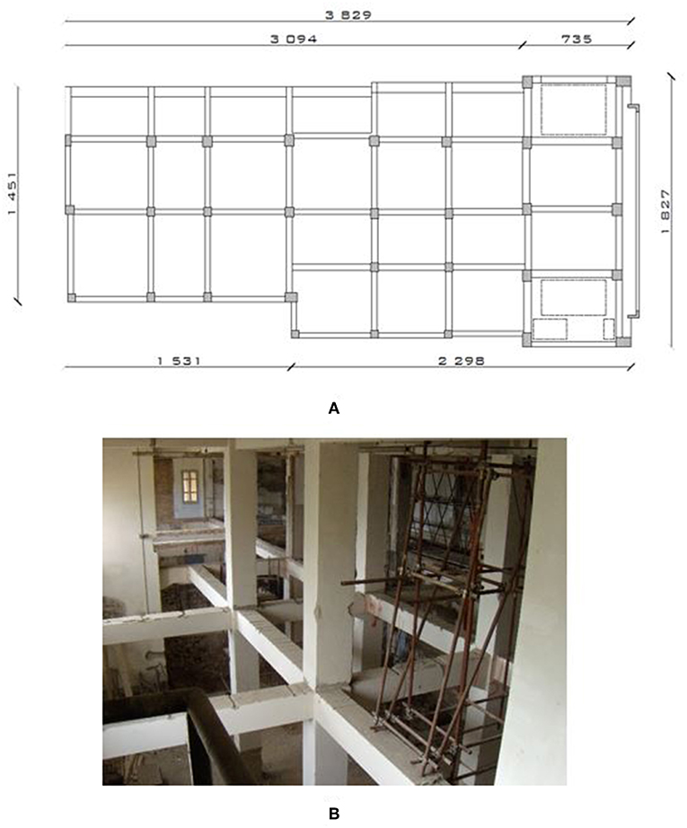
Figure 8 . Existing grid of RC beams. (A) Plan configuration (dimensions in centimeters), (B) view of current conditions.
As far as the base isolation system is concerned, it will be realized by the combination of two different devices, consisting of reinforced rubber elastomeric devices and flat low-friction sliders. Their arrangement and characteristics have been chosen to minimize the eccentricity between center of mass and stiffness, and to optimize both the equivalent viscous damping ratio and the system stiffness, to reduce as much as possible the seismic demand transmitted to the superstructure. In Figure 9 the schematic layout of the isolation system and the devices details are shown. Three different rubber devices are considered (Type A2, A3 , and A4 ) as function of the maximum vertical load capacity (P E, max ) required, having different lateral stiffness (k H ) and for an equivalent damping ratio (ξ H ) of 10%, evaluated in correspondence of the maximum displacement capacity (v max ) equal to 400 mm. Totally, 54% of devices are in rubber. The remaining devices are low-friction sliders with a friction coefficient μ equal to 2%, modeled as equivalent visco-elastic devices, having a secant stiffness and a viscous damping ratio related to the entire energy dissipated, both calculated in correspondence of maximum design displacement. In order to maximize the system torsional stiffness, the rubber devices, where possible, have been perimetrically positioned. The Figure 9 also summarizes the equivalent linear characteristics of the isolation system for each limit state considered. More in detail, T is is the period of the isolated building, S e is the spectral acceleration for the period T is , K esi is the secant stiffness of the system, ξ esi is the equivalent viscous damping ratio, η is the reduction factor for the design spectra, N L is the Non-Linearity factor ( Skinner et al., 1993 ), S De is the maximum horizontal displacement of the isolation system, S D e * is the maximum displacement of the devices assessed by considering torsional effects due to accidental eccentricity by using the expressions of Italian design code ( NTC, 2008 ) (i.e., by multiplying the displacement obtained through response spectrum analysis by a factor δ = 1 + e / r 2 · x p where e is the considered eccentricity, r is the torsional radius of the system and x p is the position of the device) and α is the isolation grade of the system (i.e., T IS /T FB ).
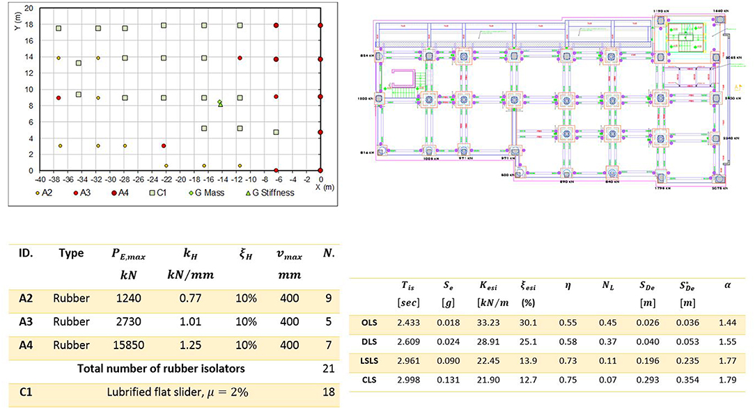
Figure 9 . Seismic isolating system: configuration and details. Where: A2, A3, and A4 are the three types of rubber isolator considered, C1 is the flat slider, G Mass, and G Stiffness are the positions of the center of masses and center of stiffness, respectively.
It should be remarked that the equivalent linear characteristics of the isolation system indicated in the Figure 9 are strongly dependent on the effective properties of the isolation devices and, in particular, on the friction coefficient of the flat sliders. As known, it is strictly related to several factors such as, among the others, the axial pressure, the sliding velocity, operating temperature, consumption of the material ( Mokha et al., 1988 ; Constantinou et al., 1990 ). To this aim, a series of numerical analyses have been carried out in order to evaluate the sensitivity of the seismic response by varying μ between the values μ = 1% and μ = 6%. Figure 10 shows the following obtained results by varying μ: the resulting fundamental period T is , the equivalent viscous damping ratio of the isolation system ξ esi , the demand in terms of spectral ordinate in acceleration S e ( T is ) and maximum displacement of devices S De ( T is ). All these parameters are calculated with a FEM model implemented as described before, by considering the secant stiffness and by referring to the seismic action expected at the Collapse Limit State. As it is easy to observe by examining the obtained results, by increasing the friction coefficient μ from 1 to 6%, although the equivalent isolation system stiffness increases (i.e., T is reduces) the lateral acceleration S e ( T is ) transmitted to the superstructure is almost constant. This is because if μ increases also the dissipation expressed through ξ esi increases. Whereas, the expected maximum displacement S De ( T is ) tends gradually to reduce, increasing the capacity/demand ratio and thus increasing the safety factor.
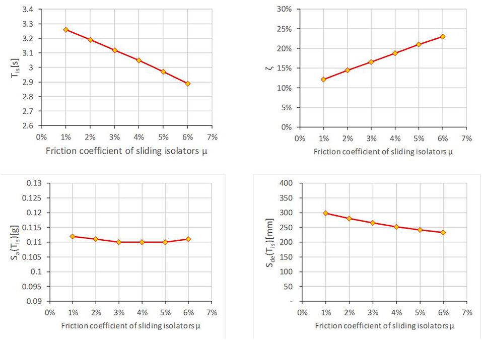
Figure 10 . Sensitivity analyses with the base-isolated FEM model by varying the friction coefficient of flat friction sliders.
In Figure 11 the results of modal analyses obtained in the case of base-isolated model are reported. It is noted that the dynamic response is significantly modified with respect to the fixed-base model. In particular, thanks to the balanced arrangement of the seismic devices reducing the eccentricity between the center of mass and stiffness, a regular dynamic behavior is obtained, by activating about the 90% of mass participating with the first three modes. It is also useful, in order to quantify the benefits of the applied strategy, to compare in Figure 12 the resulting floor shears and drifts over the height with the ones obtained with the fixed-base model.
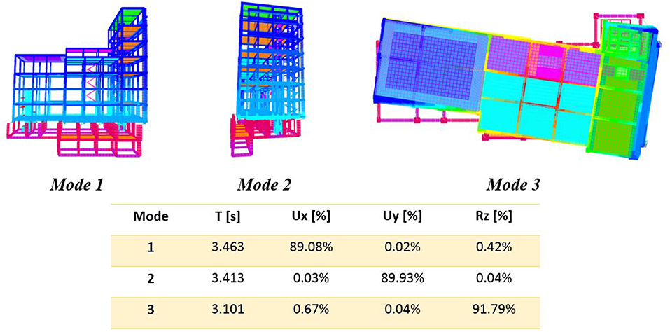
Figure 11 . Base-isolated model. Shapes and dynamic properties of the first three vibration modes.
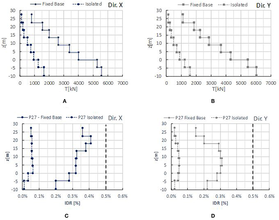
Figure 12 . Fixed-base vs. base-isolated model. Comparison over the height of floor shears (at Life Safety Limit State) for the X-direction (A) and Y-direction (B) and of Drift Ratios (at Damage Limit State) for Column 27 for the X-direction (C) and Y-direction (D) .
Figures 12A,B report the comparisons in terms of floor shear over the height between the fixed-base and isolated model for the LSLS action level. It can be noted that the shear demand in the case of base-isolated model is reduced more than the 70% at each level. While, in Figures 12C,D the comparisons in terms of interstory drift ratio for the DLS action level are shown. In this case the drift is reduced by over 80% between the two models, giving evidence of the effectiveness of the isolation system to contain also the non-structural damage. On this aspect, it should be observed that linear analyses do not allow to consider the impact of the effect of the of higher modes participation due to non-linearity effects, that could significantly change the shear and drift values, as observed in Braga et al. (2005) . However, given the limited value of the Non-Linearity factor ( Skinner et al., 1993 ) for the proposed system, these effects have not been taken into consideration herein.
Despite of a consistent seismic demand reduction reached with the isolation system, additional local interventions are needed in the case analyzed herein. Precisely, concrete jacketing interventions are foreseen to improve shear and flexural resistance on columns, while interventions with steel jacketing with CAM system ( Dolce et al., 2001 ) and composite material (i.e., FRP) are foreseen as shear and flexural reinforcements on beams. Figure 13 depicts the number of local reinforcements required by increasing the level of the designing seismic action, represented as the ratio between the capacity (a gC ) and the demand (a gD ), expressed in terms of ground acceleration at the LSLS. In the case analyzed, by considering a full seismic retrofit (i.e., when a gC / a gD = 100%), 19 interventions on columns are needed. More in detail, 12 columns need of interventions to improve shear resistance and 7 columns need of interventions to improve the flexural capacity, in both cases the intervention consists in increasing of the column section and adding of longitudinal and transverse reinforcements. Similarly, 55 interventions are needed on beams, 37 of them to improve shear resistance and 18 to improve flexural capacity. Specifically, the shear and flexural reinforcements in the support zones are provided by steel jacketing, while flexural reinforcements in the mid-span zones are provided by using FRP stripes. Three different load combinations are examined: only gravity loads, only seismic load, and both gravity and seismic loads. In Figure 13A the reinforcements needed on beams are shown, while Figure 13B reports the ones needed for columns. As it is clear to note, in this case many local reinforcements (45 reinforcements on beams and 4 reinforcements on columns) are mainly requested in order to carry on the gravity loads. Whereas, few interventions, are required for completely retrofitting the building with respect to the seismic action (i.e., obtaining a ratio a gC / a gD = 100%). In detail, they are 10 for beams and 15 for columns.
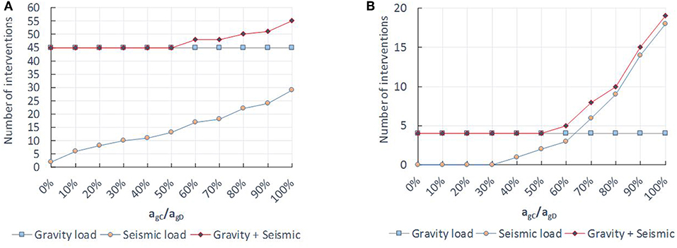
Figure 13 . Retrofitted structure: Number of local reinforcements on structural elements. Beams (A) , columns (B) .
The global cost of the intervention is about 330 e /sm (total 1.5 milion €). It should be observed that in these costs the realization of new structural elements are included (such as new stairs, new concrete wall systems and new decks) finalized to the architectural and functional rearrangement of the building, as foreseen in the project. The cost estimated in order to retrofit the building through traditional methods (only local reinforcements) is almost the same (about 1.5 million e ). Notwithstanding the two alternative solution have the same costs, the intervention through seismic isolation is less invasive, because it drastically reduces the need of local intervention in elevation. Moreover, it guarantees a higher reliability in estimating the structural response. Furthermore, the isolating system may induce many other advantages by adopting new assessment methodologies, as proposed herein in the following.
A New Methodology for Assessment of Seismic Response of a Building
In this study, it is also performed a preliminary seismic assessment of the case study with the following new methodology proposed. It is based on the idea of estimating, starting from the seismic events occurred in the past, the highest seismic action experienced by the building to which negligible or very limited damages are related. This action would become the minimum seismic action, experimentally experienced, for which the ideal superstructure of a base-isolated building would suffer negligible or very limited damages. Thus, it would represent the minimum capacity of the base isolated building.
With the aim of identifying this minimum action, an accelerometric record at the site would be ideal, even if in many cases such record is not available. Therefore, the seismic action occurred at the site should be estimated in alternative as herein proposed. The proposed procedure implies of using the Ground Motion Prediction Equations (GMPEs) together with the Ground Motions (GMs) recorded in the surrounding area to take into account the real characteristics of the considered seismic event and, in particular, the frequencies content actually involved. Then, the GMs records are scaled in the considered site by the means of proportioning factors, assessed by using the GMPE relationships. In this way, a rough assessment of the response spectra at the site for a certain earthquake is obtained.
In the considered case study, the procedure is applied by using the GMs record available in the ESM database ( Luzi et al., 2016 ) and by using the GMPE proposed by Ambraseys et al. (1996) . The reference earthquake is the Irpinia earthquake (M L = 6.9) arisen in 1980, where the structure experienced very limited damages.
By considering the magnitude of the Irpinia earthquake (M L = 6.9) and the epicentral distance of each accelerometric station, the elastic spectral accelerations expected at the i-th station, S a , i GMPE , can be estimated through the GMPE proposed by Ambraseys et al. (1996) as follows:
where T is the oscillation period, R i is the epicentral distance, C h and h 0 are coefficients given by Ambraseys et al. (1996) .
Among the several records available, it has been chosen to refer to only the GMs of sites with an epicentral distance lower than the one of Potenza (epicentral distance of Potenza, R PZ = 45 km). Therefore, the following 5 records are available: Calitri (CLT) (epicentral distance R ep = 18.9 km, maximum ground acceleration a g = 0.175 g), Bagnoli Irpino (BGL) (R ep = 21.9 km, a g = 0.187 g), Rionero in Vulture (RNR) (R ep = 35.5 km, a g = 0.096 g), Bisaccia (BSC) (R ep = 28.3 km a g = 0.096 g), and Auletta (ALT) (R ep = 23.4 km, a g = 0.057 g). Then, the expected spectral accelerations for the site of Potenza, S a , P Z G M P E , can be assessed with the previous equations as follows:
Consequently, for each oscillation period, the ratio of the spectral accelerations estimated through GMPE equations is calculated, given by the ratio of S a , P Z G M P E , for the considered site of Potenza, and S a , i G M P E , referred to the i-th accelerometric station having a R i epicentral distance:
For each accelerometric station considered, the so-obtained scale factor may be interpreted as a relative measure of the amplification (or de-amplification) of the spectral ordinate occurred in Potenza site with respect to the i-th site. Thus, it can be used as a scaling factor to de-amplify (or amplify) the spectral accelerations recorded (i.e., derived from the recorded GMs) at the i-th site in order to estimate the spectral accelerations occurred at Potenza during the seismic event. Then, the spectral accelerations for the city of Potenza are obtained as follows
where S a , i GM is the spectral ordinate for the i-th recorded ground motion.
Figures 14A,B show the response spectra for bed-rock estimated for the site of Potenza starting from each of the 5 GMs chosen, scaled with the proposed α i coefficient of the Equation (5). The spectra are separately reported for the East-West (E-W) and North-South (N-S) directions, considering also the mean spectrum for each direction considered. The latter, are compared in Figure 14C with the design spectra proposed by the Italian code ( NTC, 2008 ) for different limit states, and by considering a sub-soil of Type C (i.e., when the velocity of propagation of seismic waves V s30 is 180 <V s30 [m/s] <360). In doing so, also each mean spectrum is amplified by the stratigraphic factor proposed in the Italian code ( NTC, 2008 ) for a soil type C. As it is possible to note, the derived mean spectra are quite similar in the two directions and lower than the one of LSLS proposed by the Italian code. By considering that the fundamental vibration period of the fixed-base building is equal to T FB = 1.683 s (indicated in the Figure 6 ), the spectral accelerations estimated through the derived spectra starting from the recorded GMs result equal to 0.13 g for the E-W direction and 0.11 g for the N-S direction. These spectral accelerations, according to the new seismic methodology here presented, may be intended as the highest seismic action to date suffered in reality by the structure, and therefore experimentally experienced, for which the ideal superstructure of the base-isolated building would suffer negligible or very limited damages.
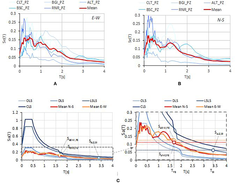
Figure 14 . Expected demand of Irpinia earthquake for the site of Potenza. (A) Recorded GMs spectra scaled for the site of Potenza in the E-W direction, (B) Recorded GMs spectra scaled for the site of Potenza in the N-S direction, (C) Mean spectra of GMs and code spectra for a soil type C.
The so-estimated spectral accelerations are higher than the one experienced by the superstructure of the isolating building (i.e., S a,LS,BIS = 0.061 g by considering the fundamental period of the building related to the Life safety Limit state), that represents the spectral acceleration considered to design the base-isolated building. It must however be observed that the estimation of the mean spectra is affected by a considerable uncertainty, due to the high variability among the scaled GMs spectra of each site, as shown in the Figures 14A,B . Nevertheless, only the record of Auletta (ALT) has spectral accelerations lower than S aLS,BI , while all the others considered records exhibit higher values.
The proposed new methodology may be intended as a preliminary assessment of the building seismic capacity, through an analysis of its capacity exhibited during previous earthquakes, without any numerical model of the structure. Therefore, with this approach, it is possible to estimate the seismic demand to which no one or very limited interventions are required, reducing significantly their invasiveness and the structural investigations. To this regard, it should be remarked that, this design philosophy is adopted by the Italian national directive for reducing the seismic risk of cultural heritage ( G.U. N. 47, 2011 ), where light interventions are permitted even in the absence of a total retrofit of the building.
Conclusions
In this paper a seismic isolation intervention on the historical building of the “ Archivio di Stato ” of Potenza has been illustrated. The case study is one of the first reinforced concrete buildings built in Italy, having an architectural value such that it has been included in the list of protected properties by the Italian Ministry of Cultural Heritage. This building has several architectural constraints and strong irregularities in plan and elevation. Thus, among the various available intervention techniques, seismic isolation has been chosen because it allows a strong reduction of demand on structural elements with a minimal impact on the architectural components.
The comparison between structural responses of fixed-base and isolated building has been pointed out that, despite of the low values of isolating grade (i.e., α = 1.77 for the LSLS), the isolating system is effective in order to reduce the seismic demand on the building. Specifically, the floor shear for LSLS have been reduced by over 70%, while the interstory drift ratios for DLS have been reduced by over 80% at each floor. However, the strong reduction of seismic demand results not sufficient to ensure a complete retrofit of the building, requiring several local interventions.
On this aspect, it has been proposed a new and fast methodology for estimating the seismic capacity exhibited by the building during the “Irpinia earthquake” of 1980. This methodology is based on a combined use of the recorded GMs of the surrounding area in conjunction with the attenuation law (GMPE). The methodology, by avoiding an implementation of a numerical model, allows to estimate the testing seismic action occurred in reality for the superstructure of the base-isolated building to which negligible or very limited damages are related. The application of this method has shown that the spectral acceleration transmitted to the superstructure with the design Italian spectra (i.e., S e = 0.061 g) would result lower than the one experienced by the ideal superstructure during the “Irpinia earthquake” (i.e., S eN−S = 0.11 g, S eE−W = 0.13 g), where the building exhibited very limited damages. Thus, this methodology has confirmed and certified the effectiveness of the isolating system demonstrating, in addition, that no local intervention would be necessary. In the future, the new methodology here presented may be also improved by accounting for the uncertainties such as, at first, the dispersion of the recorded GMs.
Data Availability
The raw data supporting the conclusions of this manuscript will be made available by the authors, without undue reservation, to any qualified researcher.
Author Contributions
All authors listed have made a substantial, direct and intellectual contribution to the work, and approved it for publication.
Conflict of Interest Statement
The authors declare that the research was conducted in the absence of any commercial or financial relationships that could be construed as a potential conflict of interest.
Alhan, C., and Gavin, H. (2004). A parametric study of linear and non-linear passively damped seismic isolation systems for buildings. Eng. Struct. 26, 485–497. doi: 10.1016/j.engstruct.2003.11.004
CrossRef Full Text | Google Scholar
Ambraseys, N. N., Simpson, A., and Bommer, J. J. (1996). Prediction of horizontal response spectra. Earthq. Eng. Struct. Dyn. 25, 371–400. doi: 10.1002/(SICI)1096-9845(199604)25:4<371::AID-EQE550>3.0.CO;2-A
Braga, F., Faggella, M., Gigliotti, R., and Laterza, M. (2005). Nonlinear dynamic response of HDRB and hybrid HDRB-friction sliders base isolation systems. Bull. Earthq. Eng. 3, 333–353. doi: 10.1007/s10518-005-1242-2
Braga, F., Gigliotti, R., and Laguardia, R. (2019). Intervention cost optimization of bracing systems with multiperformance criteria. Eng. Struct. 182, 185–197. doi: 10.1016/j.engstruct.2018.12.034
Braga, F., Gigliotti, R., and Laterza, M. (2006). Analytical Stress – Strain Relationship for Concrete Confined by Steel Stirrups and / or FRP Jackets. J. Struct. Eng. 132, 1402–1416. doi: 10.1061/(ASCE)0733-9445(2006)132:9(1402)
Caprili, S., Mattei, F., Gigliotti, R., and Salvatore, W. (2018). Modified cyclic steel law including bond-slip for analysis of RC structures with plain bars. Earthquakes Struct. 14, 187–201. doi: 10.12989/eas.2018.14.3.187
Ciampi, V., De Angelis, M., and Paolacci, F. (1995). Design of yielding or friction-based dissipative bracings for seismic protection of buildings. Eng. Struct. 17, 381–391. doi: 10.1016/0141-0296(95)00021-X
Computers and Structures Inc (2015). SAP2000 Integrated Solution for Structural Analysis and Design . Berkeley, CA.
Constantinou, M., Mokha, A., and Reinhorn, A. (1990). Teflon bearings in base isolation II: modeling. J. Struct. Eng. 116, 455–474. doi: 10.1061/(ASCE)0733-9445(1990)116:2(455)
D'Amato, M., Braga, F., Gigliotti, R., Kunnath, S., and Laterza, M. (2012a). A numerical general-purpose confinement model for non-linear analysis of R/C members. Comput. Struct. 102–103, 64–75. doi: 10.1016/j.compstruc.2012.03.007
D'Amato, M., Braga, F., Gigliotti, R., Kunnath, S., and Laterza, M. (2012b). Validation of a modified steel bar model incorporating bond-slip for seismic assessment of concrete structures. J. Struct. Eng. 138, 1351–1360. doi: 10.1061/(ASCE)ST.1943-541X.0000588
Di Sarno, L., and Manfredi, G. (2010). Seismic retrofitting with buckling restrained braces: application to an existing non-ductile RC framed building. Soil Dyn. Earthq. Eng. 30, 1279–1297. doi: 10.1016/j.soildyn.2010.06.001
Di Sarno, L., and Manfredi, G. (2012). Experimental tests on full-scale RC unretrofitted frame and retrofitted with buckling-restrained braces. Earthq. Eng. Struct. Dyn. 41, 315–333. doi: 10.1002/eqe.1131
Dolce, M., Gigliotti, R., Laterza, M., Nigro, D., and Marnetto, R. (2001). “Il rafforzamento dei pilastri in c. a. mediante il sistema CAM,” in 10th ANIDIS Conference L'ingegneria Sismica in Italia (Potenza-Matera).
Google Scholar
Faqeer, A., Faggella, M., Gigliotti, R., and Spacone, E. (2018). Effects of bond-slip and masonry in fi lls interaction on seismic performance of older R/C frame structures. Soil Dyn. Earthq. Eng. 109, 251–265. doi: 10.1016/j.soildyn.2018.02.027
G.U. N. 47 (2011). Valutazione e Riduzione del Rischio Sismico del Patrimonio Culturale con Riferimento alle Norme tecniche per le Costruzioni di cui al Decreto del Ministero delle Infrastrutture e dei Trasporti del 14 Gennaio 2008 . Italian Presidency of the Council of Ministry.
Google Maps, (2019). Google Maps. https://goo.gl/maps/BdyEstNhfyp
Ibrahim, R. A. (2008). Recent advances in nonlinear passive vibration isolators. J. Sound Vib. 314, 371–452. doi: 10.1016/j.jsv.2008.01.014
Kawamura, S., Sugisaki, R., Ogura, K., Maezawa, S., and Tanaka, S. (2000). “Seismic isolation retrofit in Japan,” in 12 th World Conference of Earthquake Engineering (Auckland).
Kelly, J. M. (1986). Aseismic base isolation : review and bibliography. Soil Dyn. Earthq. Eng. 5, 202–216. doi: 10.1016/0267-7261(86)90006-0
Kelly, J. M. (2002). Seismic isolation systems for developing countries. Earthq. Spectra 18, 385–406. doi: 10.1193/1.1503339
Laguardia, R., Gigliotti, R., and Braga, F. (2017). “Optimal design of dissipative braces for seismic retrofitting through a multi- performance procedure,” in 17th ANIDIS Conference “L'ingegneria Sismica in Italia (Pistoia).
Laterza, M., D'Amato, M., Braga, F., and Gigliotti, R. (2017b). Extension to rectangular section of an analytical model for concrete confined by steel stirrups and/or FRP jackets. Compos. Struct. 176, 910–922. doi: 10.1016/j.compstruct.2017.06.025
Laterza, M., D'Amato, M., and Gigliotti, R. (2017a). Modeling of gravity-designed RC sub-assemblages subjected to lateral loads. Eng. Struct. 130, 242–260. doi: 10.1016/j.engstruct.2016.10.044
Lignola, G. P., Di Sarno, L., Di Ludovico, M., and Prota, A. (2016). The protection of artistic assets through the base isolation of historical buildings: a novel uplifting technology. Mater. Struct. Constr. 49, 4247–4263. doi: 10.1617/s11527-015-0785-1
Luca, A., De Mele, E., Molina, J., Verzeletti, G., and Pinto, A. V. (2001). Base isolation for retrofitting historic buildings : evaluation of seismic performance through experimental investigation. Earthq. Eng. Struct. Dyn. 1145, 1125–1145. doi: 10.1002/eqe.54
Luzi, L., Puglia, R., Russo, E., and Clara D'amico, M. (2016). Engineering strong motion database, version 1.0. Seismol. Res. Lett. 87, 987–997. doi: 10.1785/0220150278
CrossRef Full Text
Martelli, A., and Forni, M. (1998). Seismic isolation of civil buildings in Europe. Prog. Struct. Eng. Mater. 1, 286–294. doi: 10.1002/pse.2260010310
Mazza, F., and Vulcano, A. (2014). Equivalent viscous damping for displacement-based seismic design of hysteretic damped braces for retrofitting framed buildings. Bull. Earthq. Eng. 12, 2797–2819. doi: 10.1007/s10518-014-9601-5
Mokha, A., Constantinou, M., and Reinhorn, A. M. (1988). Teflon Bearings in Aseismic Base Isolation: Experimental Studies and Mathematical Modeling . Technical report, NCEER, Buffalo: NY.
Mokha, A., Navichandra, A., Constantinou, M. C., and Zayas, V. (1996). Seismic isolation of large historic building. J. Struct. Eng. 122, 298–308. doi: 10.1061/(ASCE)0733-9445(1996)122:3(298)
NTC (2008). Norme Tecniche per le Costruzioni D.M. 14 Gennaio 2008 . Rome: Italian Ministry of Infrastructure.
NTC (2018). D.M. 17.01.18 Aggiornamento delle ‘Norme Tecniche per le costruzioni .’ Rome: Italian Ministry of Infrastructure.
R.D. (1939). Norme per L'esecuzione di Opere in Conglomerato Cementizio Semplice o Armato - R.D. 16.11.1939 n 2229. Rome: Regno d'Italia.
Skinner, R. I., Robinson, W. H., and McVerry, G. H. (1993). An Introduction to Seismic Isolation . Chichester: John Wiley & Sons.
Tomazevic, M., Klemenc, I., and Weiss, P. (2009). Seismic upgrading of old masonry buildings by seismic isolation and CFRP laminates : a shaking-table study. Bull. Earthq. Eng. 2009, 293–321. doi: 10.1007/s10518-008-9086-1
Verderame, G. M., Stella, A., and Cosenza, E. (2001). “Le proprietà meccaniche degli acciai impiegati nelle strutture in c. a. realizzate negli anni 60” in 10th ANIDIS Conference “L'ingegneria Sismica in Italia (Potenza-Matera).
Keywords: cultural heritage, monuments, reinforced concrete, seismic vulnerability, seismic retrofit, seismic isolated buildings
Citation: D'Amato M, Gigliotti R and Laguardia R (2019) Seismic Isolation for Protecting Historical Buildings: A Case Study. Front. Built Environ. 5:87. doi: 10.3389/fbuil.2019.00087
Received: 15 February 2019; Accepted: 18 June 2019; Published: 03 July 2019.
Reviewed by:
Copyright © 2019 D'Amato, Gigliotti and Laguardia. This is an open-access article distributed under the terms of the Creative Commons Attribution License (CC BY) . The use, distribution or reproduction in other forums is permitted, provided the original author(s) and the copyright owner(s) are credited and that the original publication in this journal is cited, in accordance with accepted academic practice. No use, distribution or reproduction is permitted which does not comply with these terms.
*Correspondence: Raffaele Laguardia, raffaele.laguardia@uniroma1.it
This article is part of the Research Topic
Seismic Analysis and Retrofitting of Historical Buildings
Structural Performance of Hill Buildings During Earthquakes
- Conference paper
- First Online: 28 July 2023
- Cite this conference paper

- Prateek Roshan ORCID: orcid.org/0000-0001-6127-3270 11 &
- Shilpa Pal ORCID: orcid.org/0000-0001-9215-125X 11
Part of the book series: Lecture Notes in Civil Engineering ((LNCE,volume 329))
Included in the following conference series:
- Symposium in Earthquake Engineering
141 Accesses
The dynamic behaviour of reinforced concrete (RC) buildings in hilly areas varies from building stocks on flat terrains. Due to the inherent mass, stiffness, and structural irregularity, buildings on slopes experience amplified torsional forces under seismic excitations. Some typical structural configurations of buildings in hill cities were identified. Dynamic analyses were carried out on the analytical models simulating the hill building configurations. These models were then subjected to seismic excitations along and across-slope directions. The dynamic characteristics and seismic responses of these hill buildings were recorded. The findings of the analysis are presented and discussed in terms of the fundamental period of vibration, storey drift, maximum top storey displacements, base shear and are finally compared within the considered configurations of hilly buildings. Analysis results reveal that the shorter columns on the uphill side being stiffer attract a higher amount of shear force, eventually leading to the collapse. Thus, short column effect is one of the critical patterns of structural response observed amongst buildings on slopes. This study concludes that the buildings on hills possess lower seismic capacity and are more prone to damage during seismic events than regular symmetric buildings on flat terrain. Some insights and suggestive measures to help reduce the failure of building stocks in hilly areas are also discussed.
This is a preview of subscription content, log in via an institution to check access.
Access this chapter
- Available as PDF
- Read on any device
- Instant download
- Own it forever
- Available as EPUB and PDF
- Durable hardcover edition
- Dispatched in 3 to 5 business days
- Free shipping worldwide - see info
Tax calculation will be finalised at checkout
Purchases are for personal use only
Institutional subscriptions
IS 1893 (Part 1)-2016. IS 1893 (Criteria for Earthquake resistant design of structures, Part 1:General Provisions and buildings). (2016)
Google Scholar
Bilham R., Szeliga W.: Interaction between the Himalaya and the flexed Indian plate-spatial fluctuations in seismic hazard in India in the past millennium? In: AIP Conference Proceedings. vol. 1020, no. PART 1, pp. 224–231. (2008). https://doi.org/10.1063/1.2963839
Wilkinson, S., et al.: The MW 7.8 Gorkha, Nepal Earthquake of 25 April 2015, A field report by EEFIT,” (2019). [Online]. https://www.istructe.org/resources/report/eefit-mission-report-gorkha-nepal/
Rupakhety, R., Olafsson, S., Halldorsson, B.: The 2015 Mw 7.8 Gorkha earthquake in Nepal and its aftershocks: analysis of strong ground motion. Bull. Earthq. Eng. 15 (7), 2587–2616 (2017). https://doi.org/10.1007/s10518-017-0084-z
Article Google Scholar
EERI. The Mw 6.9 Sikkim-Nepal Border Earthquake of September 18, 2011,” (2012)
Prajapati, S.K., Kumar, A., Chopra, S., Bansal, B.K.: Intensity map of Mw 6.9 2011 Sikkim-Nepal border earthquake and its relationships with PGA: distance and magnitude. Nat. Hazards 69 (3), 1781–1801 (2013). https://doi.org/10.1007/s11069-013-0776-x
Rehman, K., Qadri, S.M.T., Ali, A., Ali, A., Ahmed, S.: Analysis of the devastating Kashmir earthquake 2005 aftershocks. Arab. J. Geosci. 9 (5), 1–9 (2016). https://doi.org/10.1007/s12517-016-2418-6
Ministry of Earth Science & Bureau of Indian Standards, “Seismic zoning map of India,” 2021. https://pib.gov.in/PressReleasePage.aspx?PRID=1740656#:~:text=As per the seismic zoning, and remaining in zone II. Accessed 19 July 2022
Surana, M., Singh, Y., Lang, D.H.: Effect of irregular structural configuration on floor acceleration demand in hill-side buildings. Earthq. Eng. Struct. Dyn. 47 (10), 2032–2054 (2018). https://doi.org/10.1002/eqe.3054
Ghosh, R., Debbarma, R.: Effect of slope angle variation on the structures resting on hilly region considering soil–structure interaction. Int. J. Adv. Struct. Eng. 11 (1), 67–77 (2019). https://doi.org/10.1007/s40091-019-0219-3
Vishwakarma, R.S.: Torsional behaviour of buildings on slopes due to lateral load. Int. Inst. Inf. Technol. Hyderabad, India (2020)
Mohammad, Z., Baqi, A., Arif, M.: Seismic response of RC framed buildings resting on hill slopes. In: The Proceeding of 11th International Symposium on Plasticity and Impact Mechanics, 2016, Procedia Engineering, vol. 173, pp. 1792–1799. (2016). https://doi.org/10.1016/j.proeng.2016.12.221 .
Kumar, S., Paul, D.K.: A simplified method for elastic seismic analysis of hill buildings. J. Earthq. Eng. 2 (2), 241–266 (1998). https://doi.org/10.1080/13632469809350321
Pandey, A.D., Kumar, P., Sharma, S.: Seismic soil—structure interaction of buildings on hill slopes. Int. J. Civ. Struct. Eng. 2 (2), 535–546 (2011). https://doi.org/10.6088/ijcser.00202010132
Acharya, V., Krishna, A., Sengupta, P.: Seismic vulnerability assessment of reinforced concrete buildings. In: The Proceeding of the 16th Symposium on Earthquake Engineering, Roorkee, India, 362. (2018)
Surana, M., Meslem, A., Singh, Y., Lang, D.H.: Analytical evaluation of damage probability matrices for hill-side RC buildings using different seismic intensity measures. Eng. Struct. 207, no. July 2019, p. 110254. 2020. https://doi.org/10.1016/j.engstruct.2020.110254
Surana, M., Singh, Y., Lang, D.H.: Seismic characterization and vulnerability of building stock in hilly regions. Nat. Hazards Rev. 19 (1), 04017024 (2018). https://doi.org/10.1061/(asce)nh.1527-6996.0000275
Gwalani, P., Singh, Y., Varum, H.: Effect of bidirectional excitation on seismic performance of regular RC frame buildings designed for modern codes. Earthq. Spectra 38 (2), 950–980 (2022). https://doi.org/10.1177/87552930211047879
Surana, M., Singh, Y., Lang, D.H.: Fragility analysis of hillside buildings designed for modern seismic design codes. Struct. Des. Tall Spec. Build. 27 (14), 1–13 (2018). https://doi.org/10.1002/tal.1500
Kumar, A., Pushplata.: Building regulations for environmental protection in Indian hill towns. Int. J. Sustain. Built Environ., vol. 2, no. 2, pp. 224–231. 2013. https://doi.org/10.1016/j.ijsbe.2014.04.003
Kumar, R., Bhargava, K.: Analysis of slope stability of hilly terrain with seismic considerations. In: Proceedings of 16th Symposium on Earthquake Engineering, Roorkee, 2018, no. 392, p. 2018
Narayanan, A.R.V., Goswami, R., Murty, C.V.R.: Performance of RC Buildings along Hill Slopes of Himalayas during 2011 Sikkim Earthquake. In: Proceeding 15th World Conf. Earthq. Eng. Lisboa. (2012)
Sharma, M.L., Sinvhal, A., Singh, Y., Maheshwari, B.K.: Damage survey report for Sikkim earthquake of 18 september 2011. Seismol. Res. Lett. 84 (1), 49–56 (2013). https://doi.org/10.1785/0220120013
Joshi, G.C., Ghildiyal, S., Rautela, P.: Seismic vulnerability of lifeline buildings in Himalayan province of Uttarakhand in India. Elsevier Ltd (2019). https://doi.org/10.1016/j.ijdrr.2019.101168
Ramancharla, P., Goud, S., Bhalkikar, A., Patnala, N.: Earthquake disaster risk index report. 50 Towns and 1 District in Seismic Zones III, IV and V (2019)
Bhalkikar, A., Kumar, R.P.: A comparative study of different rapid visual survey methods used for seismic assessment of existing buildings. Structures, vol. 29, no. January, pp. 1847–1860. https://doi.org/10.1016/j.istruc.2020.12.026
Jain, S.K.: Earthquake safety in India: achievements, challenges and opportunities. Bull. Earthq. Eng. 14 (5), 1337–1436 (2016). https://doi.org/10.1007/s10518-016-9870-2
Pushplata., Kumar, A.: Building regulations: as a means of ensuring sustainable development in hill towns. J. Environ. Res. Dev., vol. 7A, no. 1A, pp. 553–560 (2012)
Kumar, A., Pushplata.: Building regulations for hill towns of India. HBRC J., vol. 11, no. 2, pp. 275–284. (2015). https://doi.org/10.1016/j.hbrcj.2014.06.006
Roshan, P., Pal, S.: Seismic safety of buildings on indian hill slopes—a review. Recent Adv. Earthq. Eng. Select Proc. VCDRR 2021 , 197–209 (2021). https://doi.org/10.1007/978-981-16-4617-1
Varum, H., Dumaru, R., Furtado, A., Barbosa, A.R., Gautam, D., Rodrigues, H.: Seismic performance of buildings in Nepal after the Gorkha earthquake. In: Impacts and Insights of the Gorkha Earthquake, Elsevier, pp. 47–63 (2018)
Rautela, P., et al.: Earthquake risk assessment around Nainital in Uttarakhand Himalaya. India J. Geogr. Nat. vol. 9, no. 1, pp. 1–6. (2019)
Roshan, P., Pal, S.: Structural challenges for seismic stability of buildings in hilly areas. Environ. Sci. Pollut. Res. (2022). https://doi.org/10.1007/s11356-022-23263-7
Paswan, A.P., Shrivastava, A.K.: Modelling of rainfall-induced landslide: a threshold-based approach. Arab. J. Geosci. 15 (8) (2022). https://doi.org/10.1007/s12517-022-10024-6
Li, Y., Xu, J., Wang, G.: Seismic fragility analysis of RC frames on steep slopes under near-fault and far-field ground motions. (2018). https://doi.org/10.15961/j.jsuese.201800352
Singh, Y., Gade, P., Lang, D.H., Erduran, E.: Seismic behavior of buildings located on slopes-an analytical study and some observations From Sikkim earthquake of 2012, [Online]. https://www.iitk.ac.in/nicee/wcee/article/WCEE2012_4201.pdf
IS:875(Part 1)-1987. Indian standard—code of practice for design loads (other than earthquake) for buildings and structures—part 1 dead loads—unit weights of building materials and stored materials
IS:875(Part 2)-1987. Indian standard—code of practice for design loads (other than earthquake) for buildings and structures—part 2 imposed loads (2015)
IS 456-2000. IS 456:2000 (Indian standard plain and reinforced concrete-code of practice) (2000)
IS:13920-2016. IS:13920-2016 (Ductile design and detailing of reinforced concrete structures subjected to seismic forces—code of practice) (2016)
Roshan, P., Pal, S., Kumar, R.: Performance assessment indexing of buildings through fuzzy AHP methodology. In: Lecture Notes in Civil Engineering, vol. 58, Springer, 2020, pp. 503–519
Roshan, P., Pal, S., Kumar, R.: Seismic damage assessment index of buildings using fuzzy-AHP approach. Int. J. Tech. Innov. Mod. Eng. Sci. (IJTIMES), vol. 4, no. 08, pp. 1011–1019. (2018) [Online]. http://www.ijtimes.com/papers/finished_papers/IJTIMESV04I08150826161847.pdf
Lizundia, B., Shrestha, S.N., Bevington, J., Davidson, R.: EERI earthquake reconnaissance team report: M7.8 Gorkha, Nepal Earthquake on April 25, 2015 and its Aftershocks. (2016)
Download references
Acknowledgements
The first author would like to thank Mr. Abhishek Prakash Paswan and Mr. Indrajeet Singh at Delhi Technological University for their valuable support during the data collection while surveying the hill cities. The authors would also like to thank the people at IIT Mandi and IIT Roorkee for guiding and helping in this research study.
Author information
Authors and affiliations.
Delhi Technological University, Delhi, India
Prateek Roshan & Shilpa Pal
You can also search for this author in PubMed Google Scholar
Corresponding author
Correspondence to Shilpa Pal .
Editor information
Editors and affiliations.
Department of Earthquake Engineering, Indian Institute of Technology Roorkee, Roorkee, Uttarakhand, India
Manish Shrikhande
Pankaj Agarwal
P. C. Ashwin Kumar
Additional information
Disclaimer: The presentation of material and details in maps used in this chapter does not imply the expression of any opinion whatsoever on the part of the Publisher or Author concerning the legal status of any country, area or territory or of its authorities, or concerning the delimitation of its borders. The depiction and use of boundaries, geographic names and related data shown on maps and included in lists, tables, documents, and databases in this chapter are not warranted to be error free nor do they necessarily imply official endorsement or acceptance by the Publisher or Author.
Rights and permissions
Reprints and permissions
Copyright information
© 2023 The Author(s), under exclusive license to Springer Nature Singapore Pte Ltd.
About this paper
Cite this paper.
Roshan, P., Pal, S. (2023). Structural Performance of Hill Buildings During Earthquakes. In: Shrikhande, M., Agarwal, P., Kumar, P.C.A. (eds) Proceedings of 17th Symposium on Earthquake Engineering (Vol. 1). SEE 2022. Lecture Notes in Civil Engineering, vol 329. Springer, Singapore. https://doi.org/10.1007/978-981-99-1608-5_29
Download citation
DOI : https://doi.org/10.1007/978-981-99-1608-5_29
Published : 28 July 2023
Publisher Name : Springer, Singapore
Print ISBN : 978-981-99-1607-8
Online ISBN : 978-981-99-1608-5
eBook Packages : Engineering Engineering (R0)
Share this paper
Anyone you share the following link with will be able to read this content:
Sorry, a shareable link is not currently available for this article.
Provided by the Springer Nature SharedIt content-sharing initiative
- Publish with us
Policies and ethics
- Find a journal
- Track your research

IMAGES
VIDEO
COMMENTS
Article ID IJIR-2292, Pages 568- 572. www.ijirem.org. Innovative Research Publication 568. Case Study o f Earthquake Resistant Structure and Its Recent. Innovation In Construction. Abhilash Thakur ...
The earthquake-resilient design of a reinforced concrete framed building is presented in this paper as a case study. A non-conventional application of the base isolation in conjunction with a tuned-mass-damper (TMD) located at basement, below the isolation floor, is studied for improving the seismic performance of the building.
structural design of the building to function as a single unit during the earthquake has become clear.Empowering rural communities to ensure seismic safety of building stock by generating awareness about earthquakes and the significance of earthquake-resistant buildings.The environment built in urban areas should be planned and
The general characteristics of the 2011 off the Pacific coast of Tohoku earthquake are explained first. The source inversion and slip distribution using near-source strong ground motions are shown in Fig. 2.2a [].Since it is necessary to understand the size of the 2011 earthquake, the comparison of slipped fault size is shown in Fig. 2.2b among the 2004 Sumatra earthquake (M = 9.1), the 1923 ...
Sustainable Design of Earthquake-Resistant Buildings Through Case Studies 243 Fig. 26 The plan view of the building depicting the distribution of shear walls Fig. 27 Shear-wave velocity log versus depth profile of the site The site was 6.1 m above mean sea level, and according to geotechnical studies, the shear-wave velocity varied between 100 ...
Abstract. Soil-pile-structure interaction (SPSI) plays an important role in assessing the vibrations internally generated within structures due to dynamic loads that could bring significant impacts on structural behavior. In this study, the effects of (SPSI) forces on the seismic response of three tall and massive building cases were ...
Earthquake Resistant Buildings Dynamic Analyses, Numerical Computations, Codified Methods, Case Studies and Examples ... Many design examples and case studies are included. Includes supplementary material: sn.pub/extras. 23k Accesses. 8 Citations. 3 Altmetric. Buy print copy. Softcover Book USD 249.99 .
This resource page provides an introduction to the concepts and principles of seismic design, including strategies for designing earthquake-resistant buildings to ensure the health, safety, and security of building occupants and assets. The essence of successful seismic design is three-fold. First, the design team must take a multi-hazard ...
The document provides information on earthquake resistant buildings including the Yokohama Landmark Tower in Japan and Burj Khalifa in Dubai. The Yokohama Landmark Tower uses flexible materials that allow it to sway during earthquakes rather than remain still. It has large tuned mass dampers and rollers underneath to minimize shaking. Burj Khalifa has a reinforced concrete core and Y-shaped ...
This paper presents a synthesis of current practices in regard to the seismic analysis, design, and retrofit of built-environments. Background information on the behavior of existing buildings subjected to earthquake loadings is gathered and rehabilitation methodologies are elaborated. The first part of the review examines design standards and guidelines that are used in the structural ...
Taipei 101, Taiwan | Earthquake Resistant Building Architect: C.Y. Lee and Partners Year of completion: 2004 Standing 508 m tall, making it the 10 th tallest building in the world as of 2020, Taiwan's giant has had to have gone through complex engineering and clever architectural planning that went into building this structure (construction ...
Designed to be flexible as well as structurally resistant. Because of the height of Taipei 101, and the building being located 660 feet away from a major fault line, Taipei 101 used high-performance steel construction and concrete columns. Most famously, RWDI designed a 660-tonne steel pendulum that serves as a tuned mass damper.
3. Definition of the problem. The structural system of a building is what keeps it standing. Therefore, the most important rules of earthquake-resistant building design are the necessity of designing the structural system in accordance with the regulations, using adequate and suitable materials during its construction, and setting it up according to earthquake scenarios (Celep Citation 2018).
† It is only in case of buildings with high geometric irregularities in vertical or horizontal plane (plan), the code recommends a dynamic two- or three-dimensional frame analysis. Fig. 9.5 Typical modern commercial building with cladding and glass fascia 690 9 Earthquake Resistant Design and Analysis of Buildings
5.5 CASE STUDY OF EARTHQUAKE RESISTANT STRUCTURE An earthquake is the sudden shaking of the surface of the earth caused by the passage of seismic waves through the earth's crust. During the earthquake, vibrations occur in all directions radiating from the epicenter. The sudden release of energy cause structure to
Earthquake resistant design of buildings depends upon providing the building with strength, stiffness and inelastic deformation capacity which are great enough to withstand a given level of earthquake-generated force. This is generally accomplished through the selection of an appropriate structural configuration and the careful detailing of ...
The main idea of the proposed simplified methodology is the following: if a fixed base-building has experienced an earthquake in the past with negligible or limited damages, the seismic intensity of that earthquake may be intended as an experimental proof related to the building capacity, or rather, to the capacity of the superstructure portion ...
Reinforced concrete design code IS 456: (2000), earthquake resistant design code IS1893 Part 1: (2016) and RC ductile detailing code IS 13920: (2016) are referred to in the present study. The dynamic characteristics and seismic responses of these structural models are recorded in terms of the fundamental time period of vibration, storey drift ...
Hawa mahal,Kanchenjunga apartments,World one tower,Empire state building,Sullivan centre,Eureka towers. high rise buildings case study. ... OF EARTHQUAKE ON REINFORCED CONCRETE BUILDINGS 10 ROLES OF FLOOR AND MASONRY WALLS SLABS 11 STRENGTH HIERARCHY 12 EARTHQUAKE RESISTANT BUILDING 13 EARTHQUAKE DESIGN PHILOSOPHY 14 REMEDIAL MEASURES TO ...