This genius student uses the power of AI and a 3D printer to 'handwrite' their homework
A+ material.
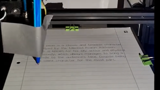
As technology advances, you can always count on one thing: students will use it to avoid doing homework. One industrious student not only got an AI chatbot to do their homework assignment, but they also rigged it to a 3D printer to write it out on pen and paper, expending the maximum amount of effort required to do the minimum amount of homework. Bravo!
TikTok user 3d_printer_stuff shared a series of videos on how they programmed a 3D printer to produce homework with the answers that ChatGPT wrote.
They gave ChatGPT their assignment; it spit out an answer, and then they copy/pasted that text over to 3dwriter . As you can see, once you sort out the proper spacing and mount a pen onto your 3D printer, 3dwriter can write out the AI-generated text onto a sheet of paper perfectly between the margins. The tutorial video shows the process step-by-step.
ChatGPT has been in the news recently after Microsoft said it would invest $10 billion in OpenAI . The company developed an AI chatbot that scrapes the internet to produce long-form answers to questions in a human-like fashion. This is exactly why ChatGPT has already been banned in New York City public schools over cheating and plagiarism concerns. Ultimately the fear is that students will use it as a crutch and hinder the development of critical thinking skills, which is why the NYC Dept. of Education restricted access to the AI chatbot on its schools' computers. I don't blame them, considering one of the videos shows math homework being done on the fly.
@3d_printer_stuff ♬ Calm LoFi song(882353) - S_R
Of course, as many comments suggest, the next logical step in 3d_printer_stuff's scheme should be to train an AI to mimic their handwriting. That way, they could fool a teacher since the handwriting shown here is just a little too perfect. You could also use these tools for non-cheating purposes, I guess. I'd argue that setting up a rig to do your homework takes more time than just doing the homework yourself, but I applaud the hustle nonetheless.
Either way, it's interesting to see what the cross-section of AI and automation can produce that doesn't involve it being "light outs for us all," according to one CEO. I nor PC Gamer endorse cheating or scamming your way out of doing homework. We do think it's cool, though.
Best SSD for gaming : The best solid state drives around Best PCIe 4.0 SSD for gaming : Speedy drives The best NVMe SSD : Slivers of SSD goodness Best external hard drives : Expand your horizons Best external SSDs : Fast, solid, and portable

The biggest gaming news, reviews and hardware deals
Keep up to date with the most important stories and the best deals, as picked by the PC Gamer team.

Jorge is a hardware writer from the enchanted lands of New Jersey. When he's not filling the office with the smell of Pop-Tarts, he's reviewing all sorts of gaming hardware, from laptops with the latest mobile GPUs to gaming chairs with built-in back massagers. He's been covering games and tech for over ten years and has written for Dualshockers, WCCFtech, Tom's Guide, and a bunch of other places on the world wide web.
Meta is reportedly back on its wearables bit: this time it wants to stick cameras on earbuds for AI
OpenAI unveils GPT-4o with a video of a man making small talk with his phone and I cannot pretend it's not really weird
Today's Wordle answer for Wednesday, May 15
Most Popular
- 2 Best ultrawide monitor for gaming in 2024: the expansive panels I recommend for PC gamers
- 3 Best wireless gaming keyboard in 2024
- 4 Best gaming laptops in 2024: I've had my pick of portable powerhouses and these are the best
- 5 Best gaming chairs in 2024: the seats I'd suggest for any gamer
- 2 Homeworld 3 review
- 3 Little Kitty, Big City review
- 4 Animal Well review
- 5 Gigabyte Aorus CO49DQ review
- Online Text to STL
- 3D Printed Soldering Helper
- 3D Printed Coin Vault
- 3D Printed FLARE GUN (PROP/REPLICA) MULTI PART
- 3D Printed Mini Container with PET Bottle Cap Size
TEST 3D PRINTS
Easy & Fun Things to 3D Print
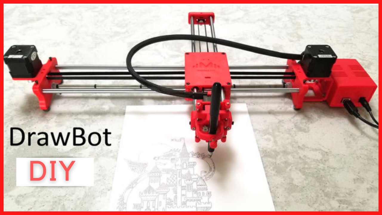
How To Make DIY Pen Plotter / Homework Writing Machine at Home
This Drawing Robot/Pen Plotter/Drawing Machine is similar to the commercially available AxiDraw. It is powered by an Arduino Uno controller, uses a CNC Shield, and GRBL firmware.
The cost to build the Drawing Robot is between $75 and $100 depending on where you buy your parts and whether you already own some of the parts such as the Arduino.
Parts and Materials Required
- 2 x Nema 17 Stepper Motors
- 2 x Linear Rod M8 x 450mm for X Axis
- 2 x Linear Rod M8 x 350mm for Y Axis
- 2 x Linear Rod 3mm for Z Axis (you can get it from old CDROM)
- 1 x Threaded Rod M8 x 480mm
- 8 x LM8UU Bearings
- 1 x Servo Sg90
- 1 x Spring 5m (from ball point pen)
- 2 x GT2 Pulley, 16 teeth
- 5 x Bearing 624zz
- 1 x 2000mm GT2 belt
- 1 x Arduino Uno
- 1 x CNC Shield
- 2 x A4988 Stepper driver with heatsink
- 6 x Jumpers
- 1 x 12V 2A Power Supply
- 4 x 5/16in-18
- 13 x Phillips M3-0.5 x 16mm
- 4 x Phillips M3-0.5 x 6mm
- 5 x Phillips M4-0.7x 35mm
- 1 x Hex M3-0.5 x 20mm
- 4 x 5/16in washer
- 4 x M3 washers
3D Printing
- Download the files from Thingiverse
- Open the 3D models in Cura or any other slicer(Sli3er, Simplify 3D, etc.)
- Use 75% infill on all the parts (An infill of 70 – 100% will work as well)
- Printed all the parts with 0.10 – 0.20 mm layer height
- Printed with Hatchbox Red PLA
- Use supports on the Penholder, Slider, X_Support_L and the X_Support_R
Note: The longest part took around 9hrs and the shortest took 30 minutes to print
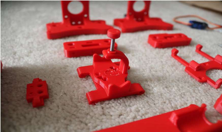
3D Printed Parts
Cut your Linear Rods
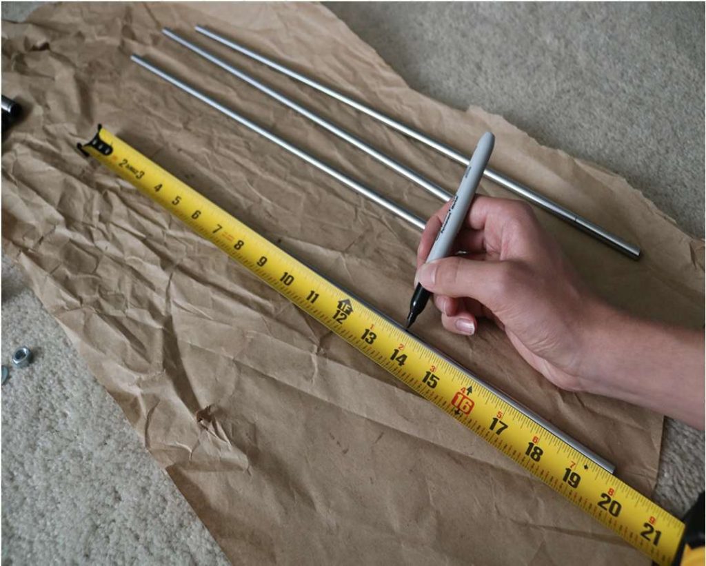
Use a measuring tape and sharpie to mark the spots where the rods need to be cut
- Use a vise to hold the rods in place when you cut them
- Remember that you need (2) 350mm and (2) 450mm long linear rods
- On the threaded rod, mark your cutting point at 470mm
Assemble the X-Axis (Linear/Threaded Rods)
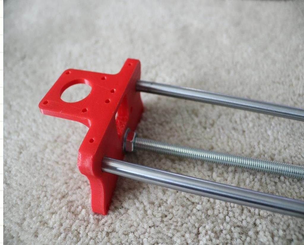
Take the (2) 450mm linear rods and insert them into either x-support part
- Use may need to use a round file to smooth out the holes that you insert them in
- Also, you can use a rubber mallet to help insert the rods
Now take the threaded rod and insert it in the hole below. Feed a 5/16in washer and 5/16in nut on both sides of the x-support part
Assemble the X-Axis (Bearings)
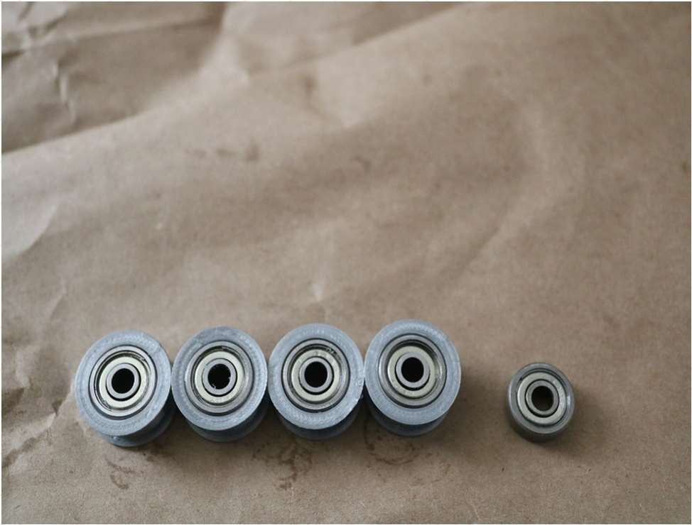
Now you want to push the LM8UU bearings into their place on the top and bottom clamshell (The top and bottom clamshell take (4) bearings each)
Take (4) 624zz bearings and push them through the 3D-printed idler pulleys. Leave the 5th bearing for later when you assemble the Y-axis
Assemble the X-Axis (Carriage)
- Get (4) M3-0.5 x 20mm screws, (4) M3 nuts, (4) M3 washers and (4) 624zz bearings with the idler pulleys installed
- Take one screw and feed a washer through it, the washer will rest on the bearing. The nut will be at the bottom of the carriage, which will secure the bearing in place

Assemble the X-Axis (X-Support)
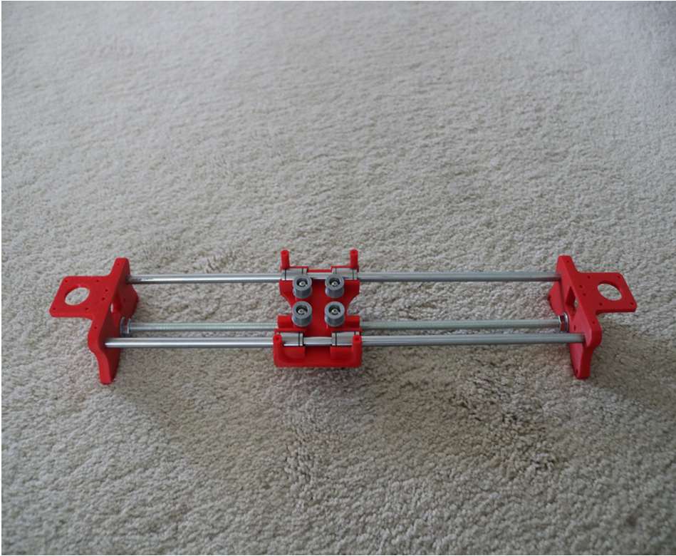
- Slide the clamshell through the 450mm (X-axis) linear rods
- Use a rubber mallet again to attach the last X-support on the linear rods
- Make sure that the rods stick out equally on both sides
- Slide the other end of the threaded rod through the hole on the X-support
- Put on the last set of nuts and washers to hold the X-support in place
- Now that the X-axis is complete, you can use (2) Phillips M3-0.5 x 16mm screws per X-support to help keep the linear rods from sliding
Assemble the X-Axis (Stepper Motors)
- Use an appropriate sized allen wrench to attach the 16 teeth pulleys on the stepper motor shafts
- Flipping the entire chassis around will make it easier to attach the stepper motors
- Use (8) M3-0.5 x 6mm screws and a Phillips screwdriver to attach the (2) stepper motors
Assemble the Y-Axis (Clamshell)
(Optional if you have problems keeping belt on bearings)
- Grab (4) M4-0.5 x 35mm screws and (4) M4 nuts
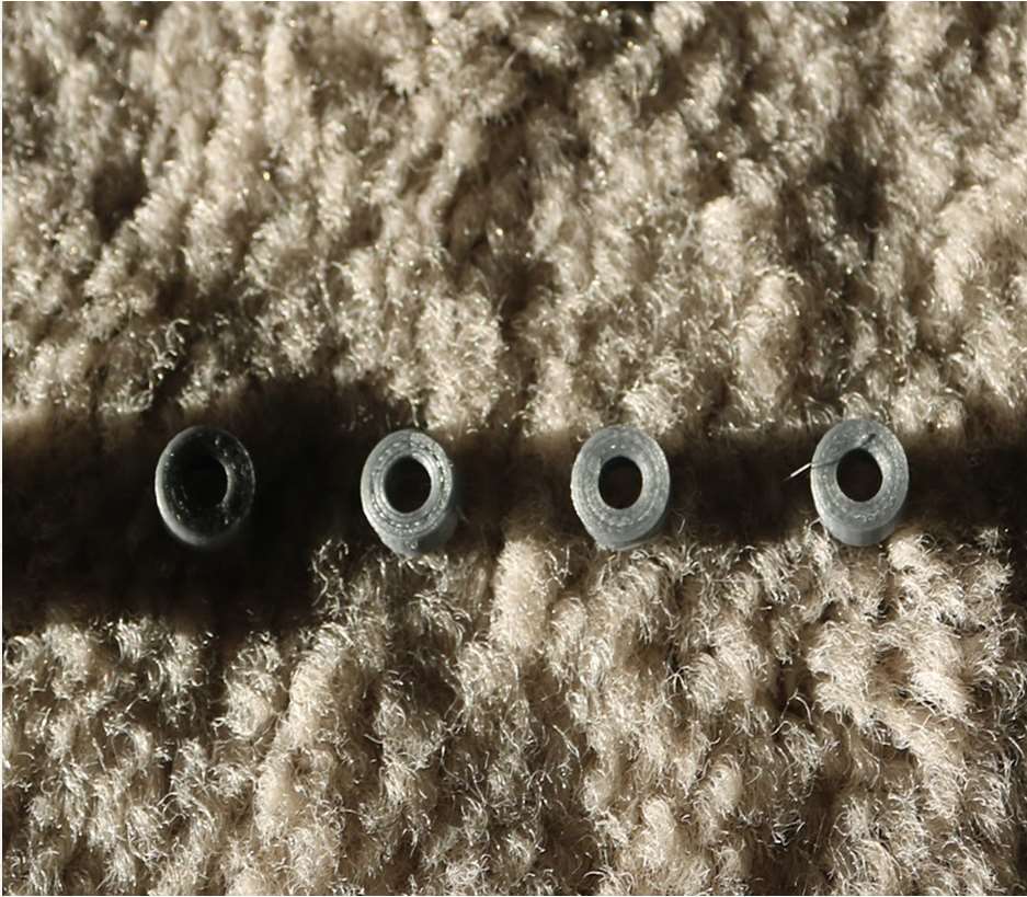
- Make sure that you have the (4) idler pulleys ( Download from Thingiversa ) and the (4) washers printed
- Insert the washers in between the two clamshells, with a screw in between
- Screw the top and bottom clamshells together
Assemble the Y-Axis (Y- Back/Front)
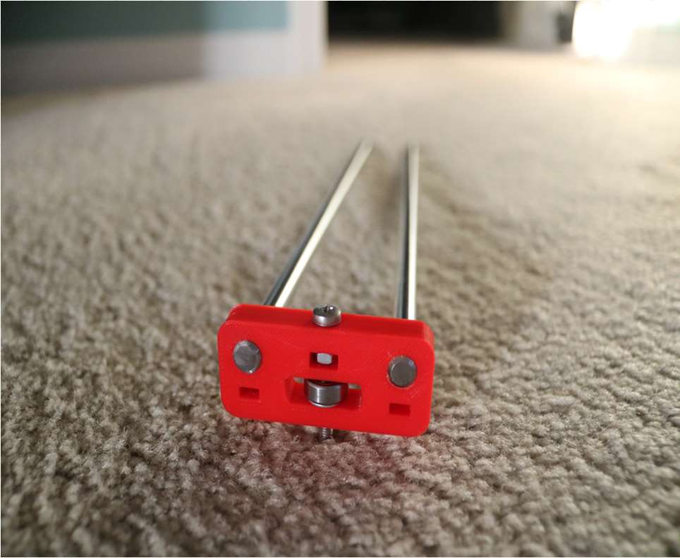
- Take the (2) 350mm linear rods and insert them the Y-back piece by using a rubber mallet
- Get (1) M4-0.5 x 35 screw, (1) M4 nut and the 5th 624zz bearing
- Get (2) M3-0.5 x 16 screws to secure the linear rods
- Slide in the bearing when inserting the screw through the Y-back piece
- Slide the the linear rods/Y-back piece through the LM8UU bearings and attach the Y-front piece using a rubber mallet
Assemble the X-Y Axis (Belt)
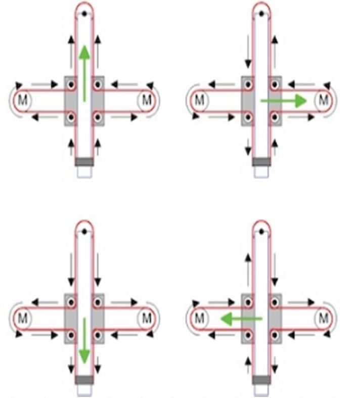
- Use a pair of needle nose pliers to help guide the GT2 belt more easily through the clamshell
- Take the two ends of the belt and slide them through the “teeth” on the Base Slider
- The belt should be tight and not loose
- Note that once the GT2 belt is on, it is normal for the clamshell not to move easily
Belt Diagram
Assemble the Z-Axis
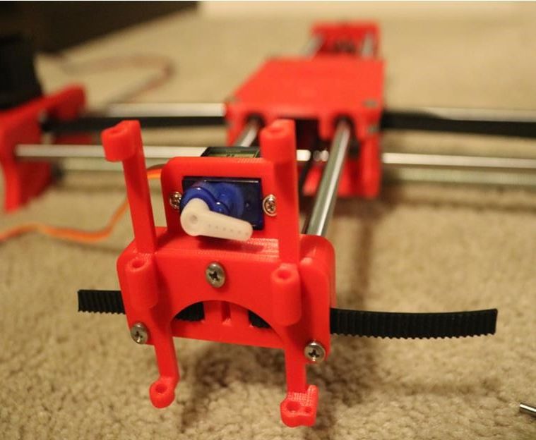
- Get (2) 3mm linear rods and the following 3D printed parts (Slider, Pen Holder, Base Slide, 3MM Metric Thumb Screw)
- Get (1) Hex M3-0.5 x 20mm screw and the Metric Thumb Screw and push them together. Use superglue to keep it together.
- Get (3) M3-0.5 x 16mm screws which you will use the secure the Base Slide to the Y-Front part. You may need to use (3) M3-0.5 nuts in order to hold it in place
- Push the Slider and Pen Holder together to make one piece
- Now take that new part and the (2) 3mm linear rods and slide the rods through the holes. Place a small spring in between the two parts so there is a little bit of pressure to lift the Slider. You may need to cut the spring a bit until there is an adequate amount of pressure on the slider.
Step By Step Video
The Original Instructions by Henry Arnold Jonathan K
- 3D Printed Hairy Lion →
12 thoughts on “ How To Make DIY Pen Plotter / Homework Writing Machine at Home ”
i constructed all the machine but when i press X+ the both X and Y axis are moving what is the problem
double check the steppers wiring
Have you solved it? I have the same problem with my machine, when I press X+, it’s necessary both motors move at same time, but, only one of them move…
Did you solve this problem?
Same problem how to solve ,?
Is it true that you didn’t use the microswitches in the final design?
Hello how to co figurę this machine to RUN on GRBL. What I mean is that GRBL interprets commands for x axis and y axis independently and if I look on your belt diagram it looks like both Motors have to run at the same time in order to move the carriage along y axis… How did you do that?
Have you solved it?
Thank you, thank you. It’s a very good built.
Is it possible to modify it to draw using brush ang oil based paint ?
Could you please tell what software/plug in and which version do you use to generate g-code for this machine?
Hello, what is the width of your belt? 6mm or 10mm? Thanks!
Leave a Reply Cancel reply
Your email address will not be published. Required fields are marked *
Save my name, email, and website in this browser for the next time I comment.

DIY Homework Writing Machine Using Arduino - 2D Pen Plotter

Introduction: DIY Homework Writing Machine Using Arduino - 2D Pen Plotter
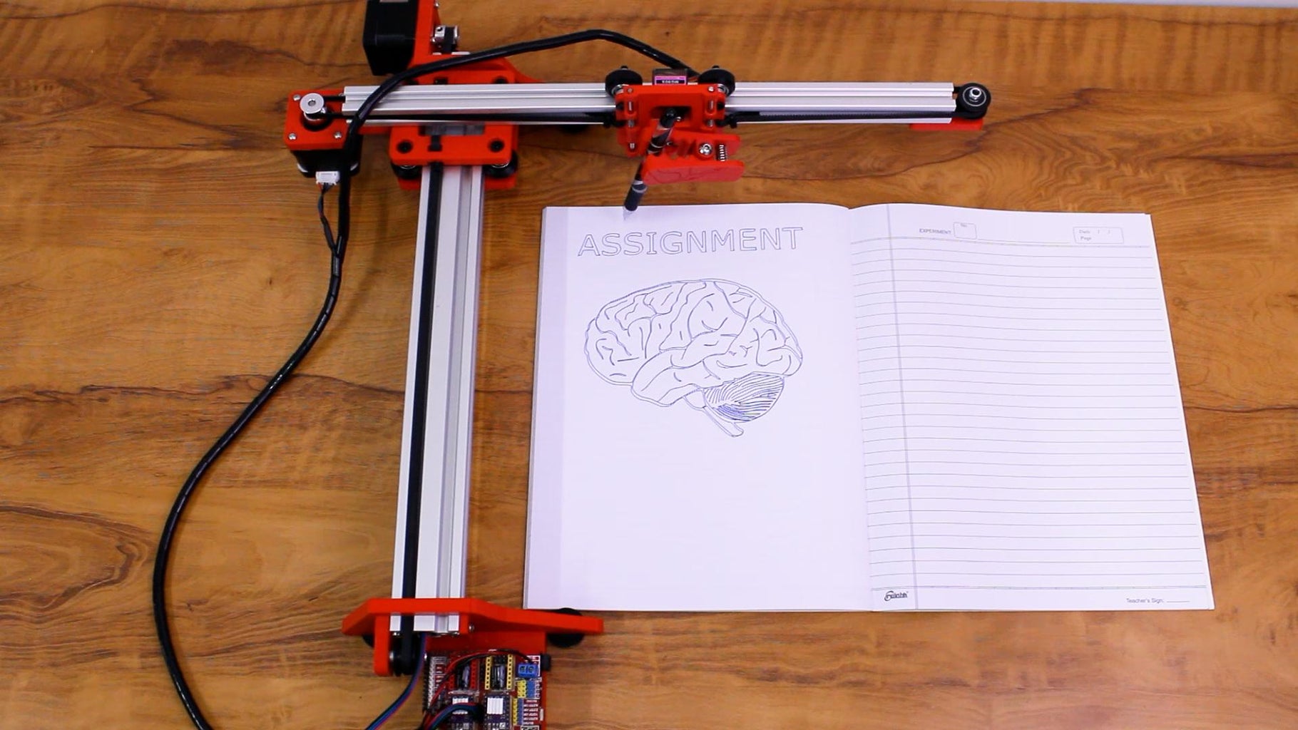
Hi, in this blog I will show you how to make your own homework writing machine also known as 2d plotter.
This machine can write on any surface using any type of pen, pencil, sketch pen or marker. This is useful when you have to complete an assignment or draw beautiful and neat diagrams for your school/college project to fetch those extra marks.
The machine has a very simple construction and can be easily assembled provided you have the right parts available. In this blog, I will explain you the step-by-step assembly of the machine, explain you the parts used, and also provide you a part list in the end with buy links so that you can order them online.

You will require a 20x20mm and a 20x40mm V Slot Aluminium extrusion profile of 400mm length each. you can also use 500mm length if you want a larger sized machine. i have prepared a complete part list/ BOM, which you can access through this link: https://bit.ly/3bKfPJJ
Step 1: Assembly - Y Axis
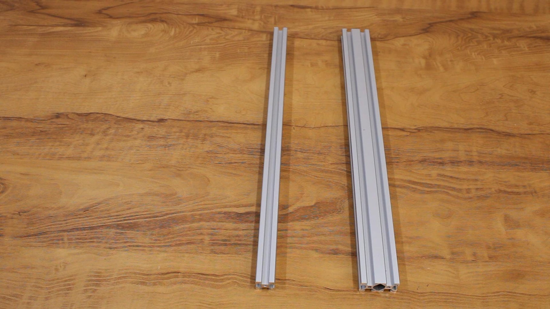
Take the 2040mm profile and attach the base plates to both the ends. Use the sliding nuts and m4 bolts to attach the base plates to the profiles. Now turn the profile and attach rubber feet to the bottom slots of the base plates. These rubber feet will hold the machine in place on smooth surfaces.

Step 2: Intersection Plate
Turn the profile back again, now attach the intersection plates and v wheel kits to the profile.
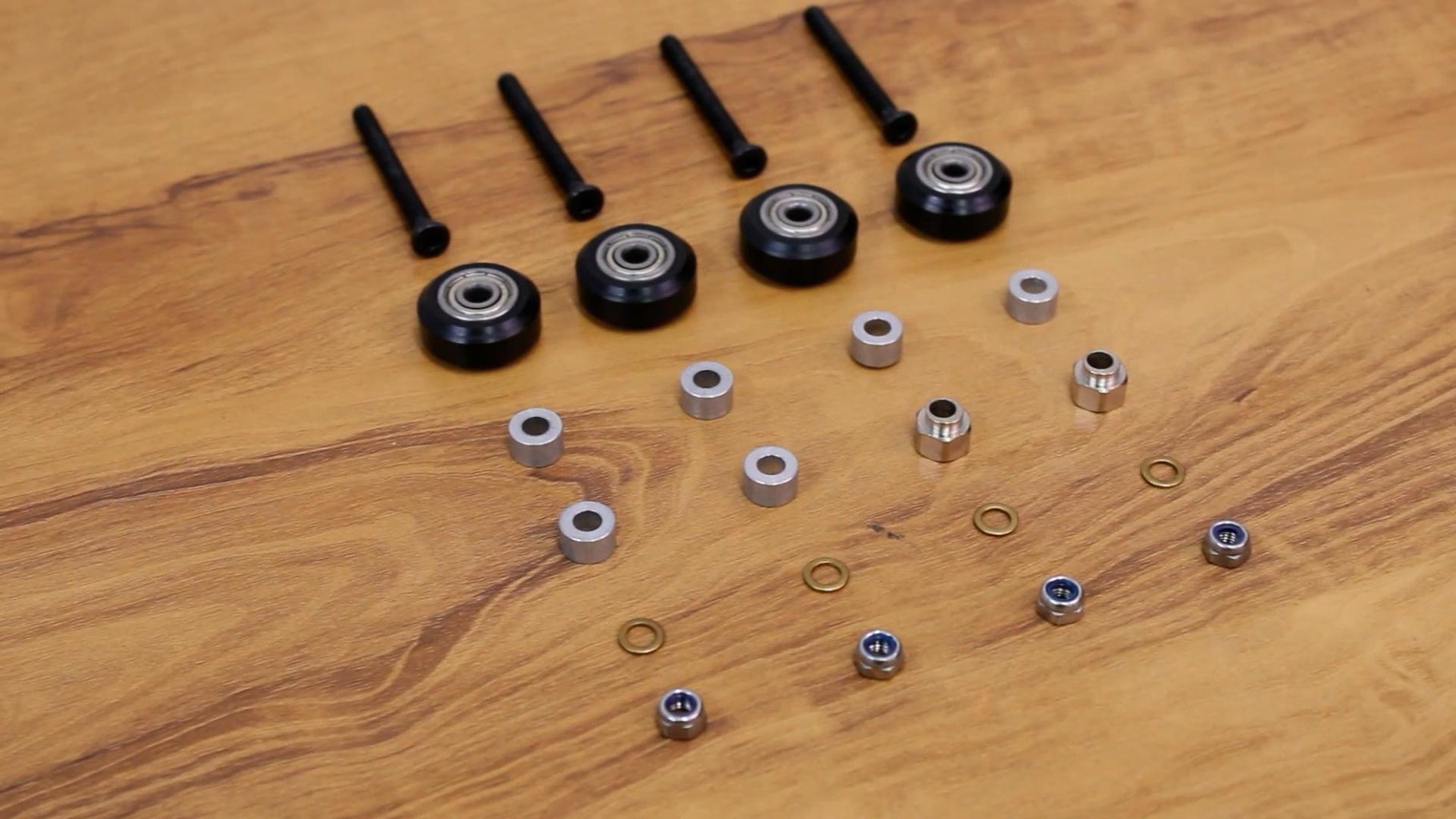
We will use Delrin v wheels to enable motion in the x and y axis. These wheels consist of 2 bearings and a wheel which runs on the v slot of the profile. This provides a smooth and sturdy motion system to our machine.
Take the top intersection plate, insert m5x45mm bolts to the plate, insert 6mm aluminium spacers on one side and eccentric spacers on the other side, 1mm shim washers, and then insert the Delrin v wheels, insert the spacers and washers again.
Now turn the 2040 profile again and place it on top of the intersection plate. The wheels and eccentric spacers are loose so the profile can be inserted easily. After the profile is inserted, place the bottom intersection plate and pass the bolts through the plate and fasten the bolts using m5 nyloc nuts. Now our intersection plate assembly is complete. Turn the profile back again and tighten the eccentric spacers using a spanner. The wheels should have a firm grip on the profile, also do not over tighten them.
Step 3: Y Axis Motor and Belt
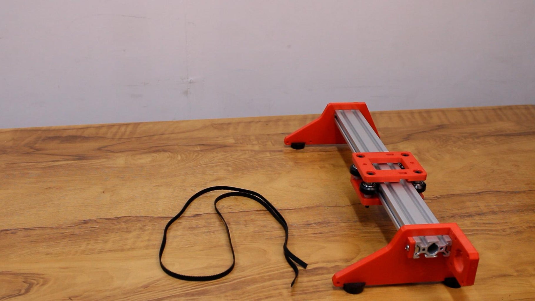
Now we will insert the gt2 timing belt in the y axis profile. Insert the belt through the v slots in the 2040mm profile. Fasten the belt using cable ties in the slots on the intersection plate. Leave some space for the gt2 pulley and idler pulley. Attach the NEMA 17 stepepr motor to the top base plate, and attach the gt2 timing pulley to the motor, pass the belt through the timing pulley. On the bottom base plate, attach the idler pulley and pass the belt through it.
You can use one technique to make sure that there is enough tension in the belt. Before fastening the belt to the intersection plate using cable ties, you can loosen the bottom base plate and bring it closer towards the intersection plate. Once the belt is attached, you can then pull the plate towards the end, which will tighten the belt and thus there will be enough tension in the belt for smooth movement.
By this we are done with the assembly of y axis.
Step 4: X Axis Assembly
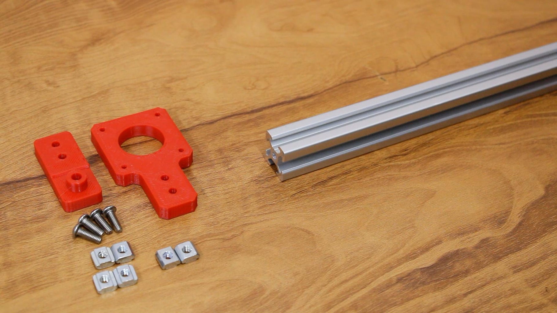
Take the 20x20mm profile and attach the motor plate and idler pulley plate to both the ends using sliding nuts and m4 bolts. Insert 2 extra m5 sliding nuts in the profile between the motor plate and idler pulley plate. Now turn the y axis assembly and place it on top of the 20x20mm profile. There are 2 holes in the top intersection plate, which are for attaching the 2 axis to the intersection plate. Align the m5 sliding nuts to the holes and attach them using m5x12mm bolts. Turn the frame upside down.
Step 5: X Axis Motor and Pulley
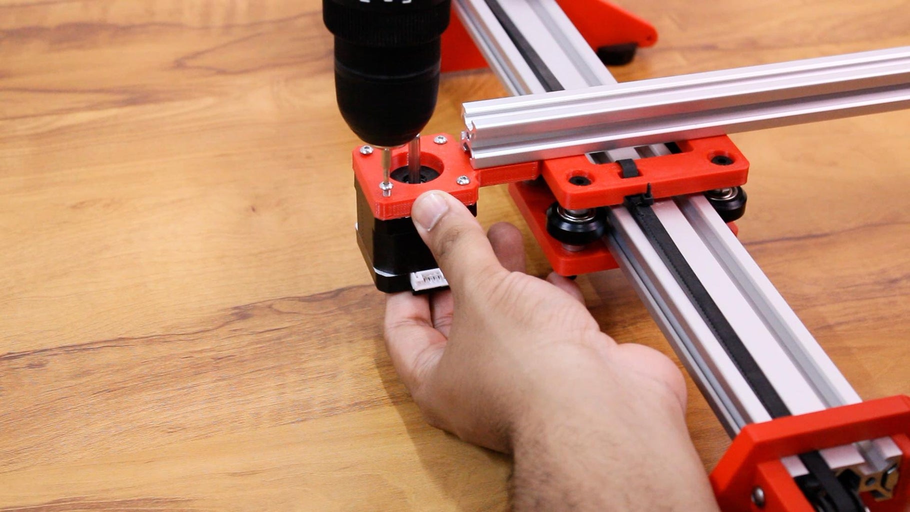
Attach the stepper motor using m3x12mm bolts and attach the idler pulley to the other end of the x axis. Use a gt2 timing belt of approx. 1 meter length and loop it from the motor and pulley
Step 6: Pen Holder Plate
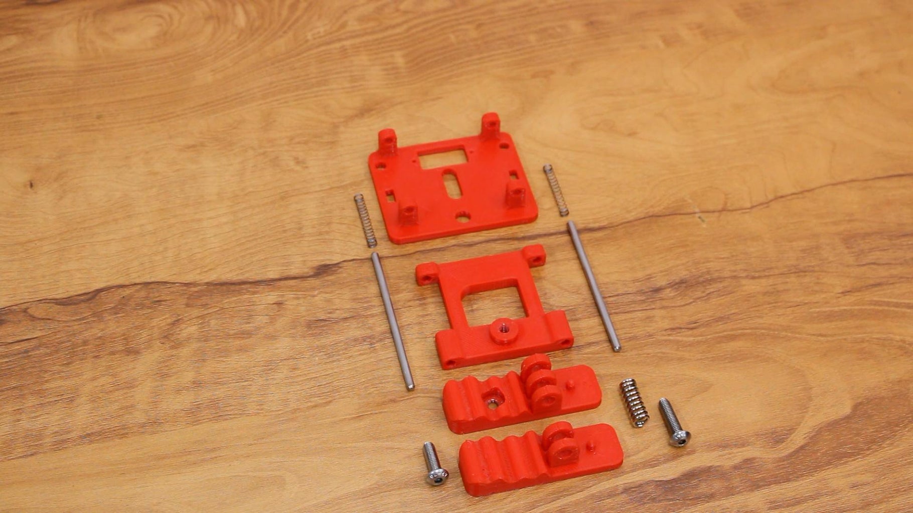
Now we will attach the pen holder plate to the x axis.
the pen holder plate includes 4 3d printed parts, 2 3mm springs, 2 3mm 80mm long stainless steel shafts, 1 20mm 3d printer bed spring, m5x15mm bolt and m5x20mm bolt.
take the base plate, insert the 3mm shafts from below, now place the movement plate above the shafts, move the shafts towards the top. now insert the springs between the shafts and the top holder, and push the shafts to the top holder. the holders are designed with tight tolerances, and the movement plate has enough gap to allow smooth movement through the shafts.
Attach the pen clip using the M5x15mm bolt, tighten the bolt to have tight movement of the clip, in order to tilt the pen while writing. now place the 20mm spring between the 2 clips, and insert the M5x20mm bolt to keep the clip intact.
Step 7: Mount the Pen Holder Plate
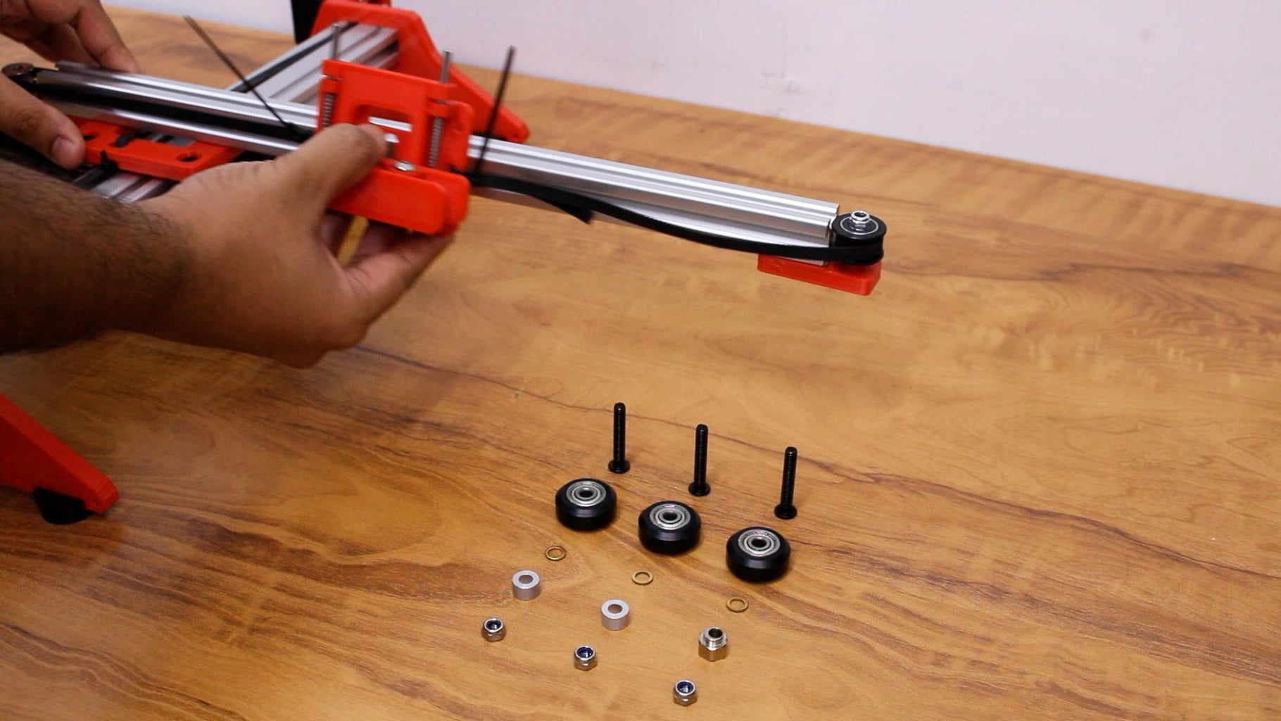
Now attach the pen holder plate to the X axis using V Wheels, the same way which we attached the intersection plate. use the eccentric spacer to tighten the grip between the wheels.
once the plate is in place, pull the pulley plate slightly outwards, to provide tension to the belt, and tighten the m5 bolts under the plate once there is enough tension in the belt.
Step 8: Electronics
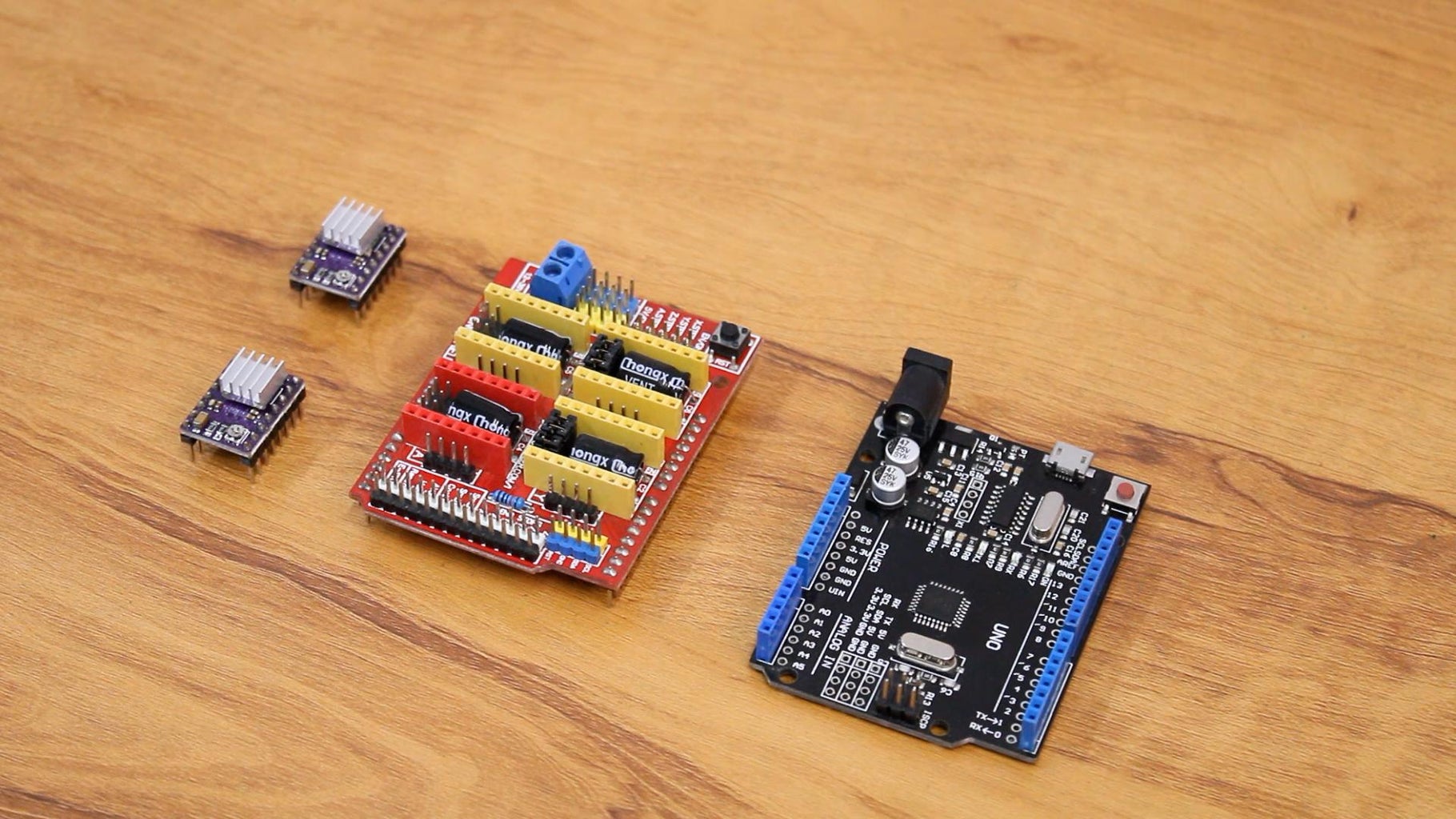
we are using an Arduino UNO along with CNC shield V3.0 for this project. we will also require 2 DRV8825 drivers to drive the stepper motors.
to power the machine, we require a 12V 2A power adapter. attach the arduino to the mount plate, and attach the mount plate to the machine
Step 9: Attach Servo
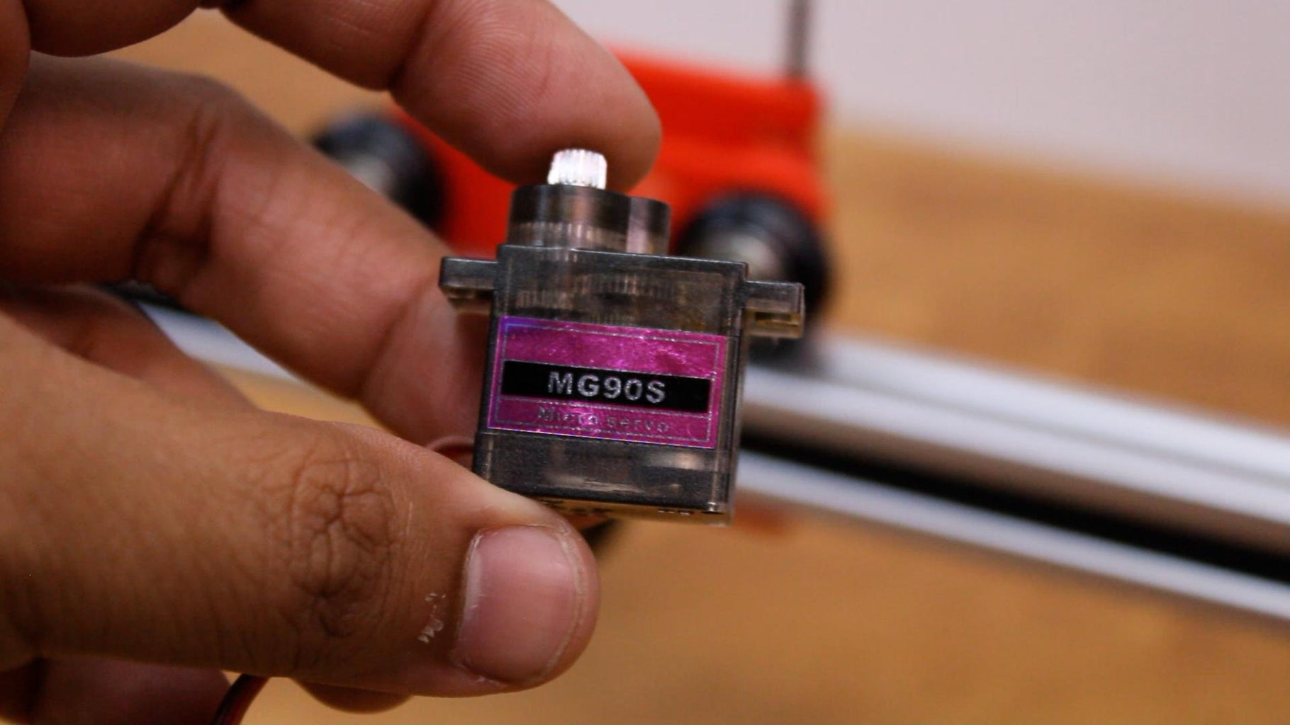
Attach the MG90s servo motor to the pen plate from the back side. use the screws provided with the servo to mount the servo motor. attach the one sided arm provided with the servo from the front and secure it with a screw
Step 10: Wiring and Test Run
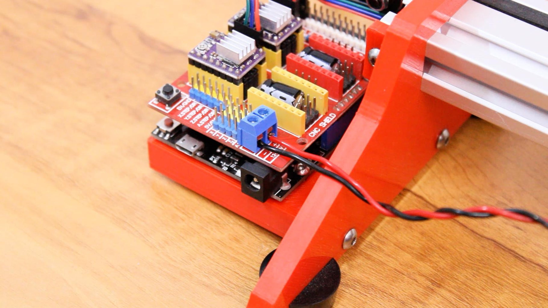
Plug the AC adapter, connect the wires to the CNC shield, and turn the adapter on. connect the USB from the arduino to your PC or laptop. now we can test the machine.
Step 11: Final Results
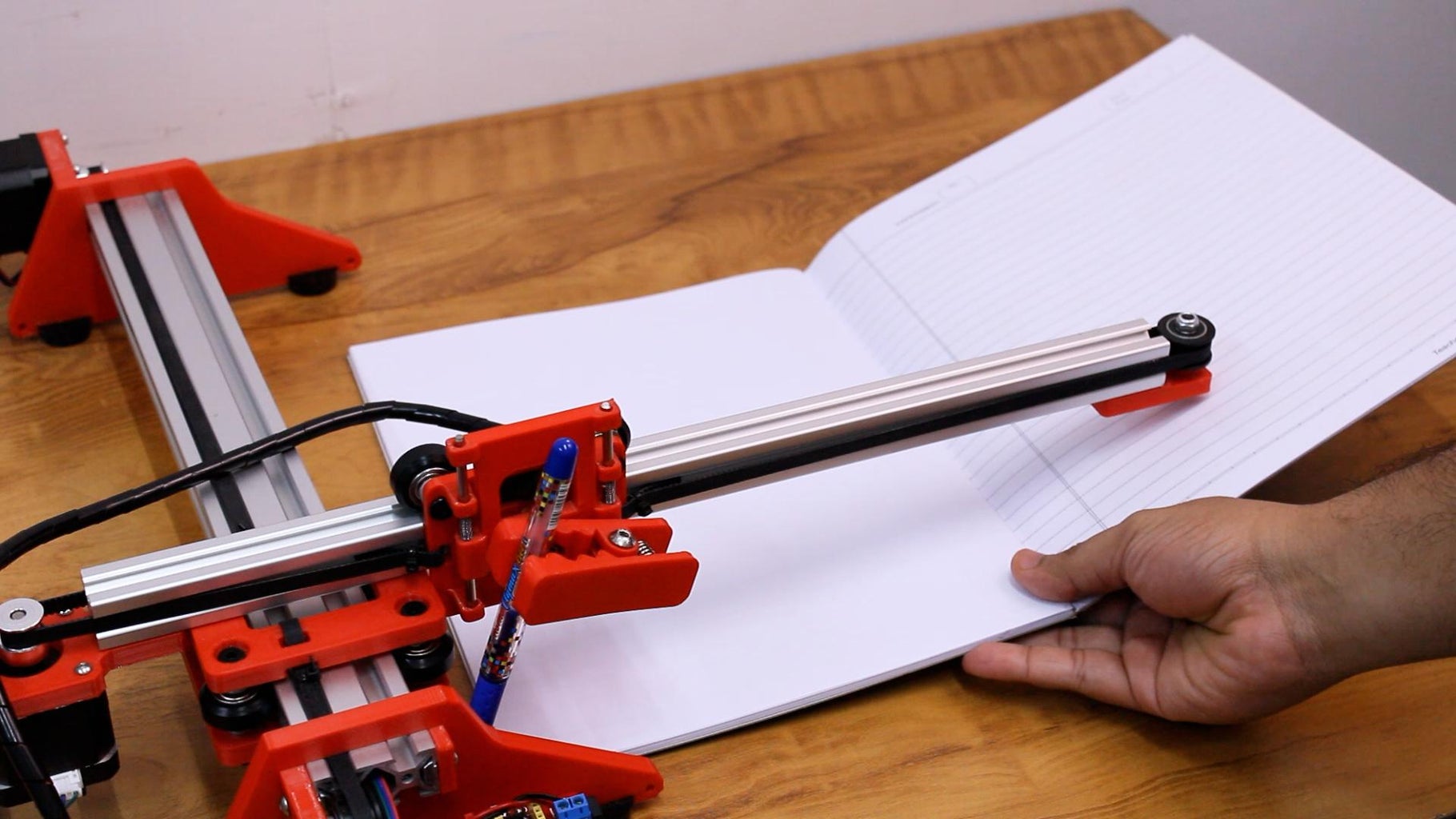
use a notebook or paper, and run the gcode file through the controller software.
you will require the following softwares to operate the machine, which i will explain in detail in the upcoming instructable.
the machine is able to accurately draw on the book and the results look good.

Recommendations

Engineering in the Kitchen - Autodesk Design & Make - Student Contest

Remake It - Autodesk Design & Make - Student Contest

Big and Small Contest

Embed the widget on your own site
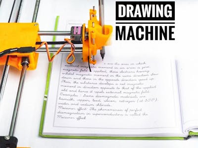
Drawing Robot/Pen Plotter/Drawing Machine is an Open Hardware version of the famous machine AxiDraw which it is a pen plotter, capable of wr

Make DIY Homework Writing Machine at Home
Step 1: parts and materials required, step 2: 3d printing, step 3: assemble the x-axis, step 4: assemble the x-axis bearing, step 5: assemble the y-axis.
- Step 6: Assemble the X-Y Axis (Belt
Step 7: Assemble the Z-Axis
Step 8: electronics, step 9: software, step 10: drawing machine at work.
- Comments (8)

Things used in this project
- Buy from Newark
- Buy from store.arduino.cc
- Buy from Adafruit
- Buy from Arduino Store
- Buy from CPC

Software apps and online services

Hand tools and fabrication machines

Drawing Robot/Pen Plotter/Drawing Machine is an Open Hardware version of the famous machine AxiDraw which it is a pen plotter, capable of writing or drawing on almost any flat surface. It can write with pens, permanent markers, pencils, and other writing implements to handle an endless variety of applications.
Its unique design features a writing head that extends beyond the machine, making it possible to draw on objects bigger than the machine itself. The biggest advantage of the machine is that it can be placed over the book because of the core XY extending design of the machine.
This Drawing Robot/Pen Plotter/Drawing Machine is similar to the commercially available AxiDraw. It is powered by an Arduino Uno controller, uses a CNC Shield, and GRBL firmware
The cost to build the Drawing Robot is between $75 depending on where you buy your parts and whether you already own some of the parts such as the Arduino.
You can find all of my projects on https://www.diyprojectslab.com/
Maximum drawing area 24 * 30 CM.
Thank You NextPCB
This project is successfully completed because of the help and support from NextPCB. Guys if you have a PCB project, please visit their website and get exciting discounts and coupons.
Free shipping 0$ PCB Prototype: https://www.nextpcb.com/pcb-quote?act=2&code=Romeo...
Thanksgiving Christmas lucky draw 100% win: https://www.nextpcb.com/christmas-lucky-draw?code...
2 x Nema 17 Stepper Motors Amazon.com
2 x Linear Rod M8 x 450mm for X Axis Amazon.com
2 x Linear Rod M8 x 350mm for Y Axis Amazon.com
2 x Linear Rod 3mm for Z Axis (you can get it from old CDROM)
1 x Threaded Rod M8 x 480mm8 x LM8UU Bearings Amazon.com
1 x Servo Sg901 x Spring 5m (from ball point pen) Amazon.com
2 x GT2 Pulley, 16 teeth Amazon.com
5 x Bearing 624zz Amazon.com
1 x 2000mm GT2 belt Amazon.com
1 x Arduino Uno Amazon.com
1 x CNC Shield Amazon.com
2 x A4988 Stepper driver with heatsink Amazon.com
6 x Jumpers Amazon.com
1 x 12V 2A Power Supply Amazon.com
- 4 x 5/16in-18
- 13 x Phillips M3-0.5 x 16mm
- 4 x Phillips M3-0.5 x 6mm
- 5 x Phillips M4-0.7x 35mm
- 1 x Hex M3-0.5 x 20mm
- 4 x 5/16in washer
- 4 x M3 washers
Download the files from Thingiverse
Open the 3D models in Cura or any other slicer.
Use 75% infill on all the parts (An infill of 70 – 100% will work as well)
Printed all the parts with 0.10 – 0.20 mm layer height
Printed with PLA
Use supports on the Penholder, Slider, X_Support_L and the X_Support_R
Note: The longest part took around 10hrs and the shortest took 30 minutes to print
PLA is fine for this design. I print at 200C on BuildTak. None of the parts require rafts or brims. I suggest supports only for the pen holder and the Z axis end plate which is standing up.
Remember that you need (2) 350mm and (2) 450mm long linear rods
Take the (2) 450mm linear rods and insert them into either x-support part
- Use may need to use a round file to smooth out the holes that you insert them in
- Also, you can use a rubber mallet to help insert the rods
Now take the threaded rod and insert it in the hole below. Feed a 5/16in washer and 5/16in nut on both sides of the x-support part
Now you want to push the LM8UU bearings into their place on the top and bottom clamshell (The top and bottom clamshell take (4) bearings each)
Take (4) 624zz bearings and push them through the 3D-printed idler pulleys. Leave the 5th bearing for later when you assemble the Y-axis
Assemble the X-Axis (Carriage)
- Get (4) M3-0.5 x 20mm screws, (4) M3 nuts, (4) M3 washers and (4) 624zz bearings with the idler pulleys installed
- Take one screw and feed a washer through it, the washer will rest on the bearing. The nut will be at the bottom of the carriage, which will secure the bearing in place
Assemble the X-Axis (X-Support)
- Slide the clamshell through the 450mm (X-axis) linear rods
- Use a rubber mallet again to attach the last X-support on the linear rods
- Make sure that the rods stick out equally on both sides
- Slide the other end of the threaded rod through the hole on the X-support
- Put on the last set of nuts and washers to hold the X-support in place
- Now that the X-axis is complete, you can use (2) Phillips M3-0.5 x 16mm screws per X-support to help keep the linear rods from sliding
- Take the (2) 350mm linear rods and insert them the Y-back piece by using a rubber mallet
- Get (1) M4-0.5 x 35 screw, (1) M4 nut and the 5th 624zz bearing
- Get (2) M3-0.5 x 16 screws to secure the linear rods
- Slide in the bearing when inserting the screw through the Y-back piece
- Slide the the linear rods/Y-back piece through the LM8UU bearings and attach the Y-front piece using a rubber mallet
Step 6: Assemble the X-Y Axis (Belt)
- Use a pair of needle nose pliers to help guide the GT2 belt more easily through the clamshell
- Take the two ends of the belt and slide them through the “teeth” on the Base Slider
- The belt should be tight and not loose
- Note that once the GT2 belt is on, it is normal for the clamshell not to move easily
- Get (2) 3mm linear rods and the following 3D printed parts (Slider, Pen Holder, Base Slide, 3MM Metric Thumb Screw)
- Get (1) Hex M3-0.5 x 20mm screw and the Metric Thumb Screw and push them together. Use superglue to keep it together.
- Get (3) M3-0.5 x 16mm screws which you will use the secure the Base Slide to the Y-Front part. You may need to use (3) M3-0.5 nuts in order to hold it in place
- Push the Slider and Pen Holder together to make one piece
- Now take that new part and the (2) 3mm linear rods and slide the rods through the holes. Place a small spring in between the two parts so there is a little bit of pressure to lift the Slider. You may need to cut the spring a bit until there is an adequate amount of pressure on the slider.
ELECTRONICS
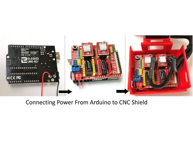
I prefer you can use Arduino uno CNC Shield
Ready to your all circuit
1) 4pcs A4988 Stepper Motor Driver
2) Expansion Board A4988 Driver
3)Arduino UNO First of all take hit sink and stick on A4988 motor Driver.
4pcs A4988 Stepper motor driver connect on expansion board A4988 driver module, then connect the arduino with expansion board and connect all wiring The shield also has a built-in micro stepping control - meaning that instead of using full steps or half steps like a large CNC would do, we can make the motors move by 1/16 or 1/32 of a step to make the laser move with the maximal precision possible. However, the motors will consume more electricity: they will get hot quicker.
To use the micro stepping modes, short some of the mode pins together. Different combinations give different resolutions. Take a look at the chart for the different configurations possible. When the shield is programmed, add the A4988 drivers to it and wire up the rest of the electronics.
To find the coils of the stepper motors, use a multimeter. If there's resistance between the two wires, you have a coil. On the schematic, the coils are represented by two wires of the same color.
Inkscape which is the graphics design software (draw or import graphics)
Inkscape MI GRBL Extension (convert graphics to G-Code)Universal G Code Sender (sends the G-Code to the robot causing drawing motion)GRBL which is the Arduino firmware (programmed into the Arduino Uno)
Arduino: https://www.arduino.cc/en/software
Universal G-code sender: https://winder.github.io/ugs_website/...
Inkscape: https://inkscape.org/release/inkscape..
4xiDraw & km laser: https://drive.google.com/file/d/1YO8-...
Processing: https://processing.org/download/
drawing to G-code processing: https://drive.google.com/file/d/1PIFx...
watch video for full setup
hookup_QLVR1z3Ob1.jpg
DIY Projects Lab
Related channels and tags.

- home automation

COMMENTS
TikTok user 3d_printer_stuff shared a series of videos detailing how it all came together, including one tutorial that shows the same steps you'd need to take if you wanted technology to do your homework, too. The student began by opening up ChatGPT and entering the task in the program.
One industrious student not only got an AI chatbot to do their homework assignment, but they also rigged it to a 3D printer to write it out on pen and paper, expending the maximum amount of effort ...
Step 2: Make Y Axis Slider. Take two 42 cm long 8 mm threaded rods, 8 mm nuts, and the stepper motor holder after all the 3D-printed parts have been completed printing. Then, as shown in the picture, passing this threaded road from the bottom holes in the stepper motor holder.
A simple demonstration of chatGPT and 3D printing technology!chatGPT website: https://openai.com/blog/chatgpt/Text from gCode: https://3dwriter.io/Visit us a...
If you are interested in this Assignment Writing Machine, please fill out this form - https://forms.gle/GqnM35X2LDD5G4iu8I was really tired of dealing with ...
So instead, they turned their 3D printer into a pen plotter. That is easy to do by attaching a pen to the 3D printer near the hot end. As long as the printer knows the Z height of the pen's tip, it can work just like a standard pen plotter. After completing that, the only thing left for 3d_printer_stuff to do was generate the g-code.
3D Printer Does Homework ChatGPT Wrote!!! ... So most 3D printers are used as 2.5 axis machines (unless you're using vase mode or non-planar printing). ... For an added bit of believability with the writing, randomly adjusting the z height slightly as it writes, would give the effect of someone adding variable pressure as they wrote ...
"In this video, we'll show you how to use the website 3dwriter.com and a 3D printer to bring your chatbot's outputs to life! We'll guide you through the proc...
Step 4: Assemble the X-Axis Bearing. Now you want to push the LM8UU bearings into their place on the top and bottom clamshell (The top and bottom clamshell take (4) bearings each) Take (4) 624zz bearings and push them through the 3D-printed idler pulleys. Leave the 5th bearing for later when you assemble the Y-axis.
Step 2: 3D Printing. 1 / 2. Download the files from Thingiverse. Open the 3D models in Cura or any other slicer. Use 75% infill on all the parts (An infill of 70 - 100% will work as well) Printed all the parts with 0.10 - 0.20 mm layer height. Printed with PLA. Use supports on the Penholder, Slider, X_Support_L and the X_Support_R
In Inkscape, navigate to 'file', 'document properties', and change the height and width to match your build plate, also change the measurement to 'mm'. Navigate to the 'img' folder in the Handwriting-Synthesis repository, and locate the 'Usage_Demo.svg' file. Drag it into Inkscape. Then right click it and click 'ungroup'.
74.9 %. free Downloads. 10000+ "homework writing machine" printable 3D Models. Every Day new 3D Models from all over the World. Click to find the best Results for homework writing machine Models for your 3D Printer.
Here we are customizing a 3D printer, a homework writing machine, a CNC sketcher (Plotter) and sticker cutter to this CNC setup. While working as a 3D printer, a filament material is melted using a heating element (Hotend) and is deposited on a plane according to the movement of the X, Y & Z axis. While working as a CNC sketcher, a pen is made ...
Get (2) 3mm linear rods and the following 3D printed parts (Slider, Pen Holder, Base Slide, 3MM Metric Thumb Screw) Get (1) Hex M3-0.5 x 20mm screw and the Metric Thumb Screw and push them together. Use superglue to keep it together. Get (3) M3-0.5 x 16mm screws which you will use the secure the Base Slide to the Y-Front part.
To calibrate, the first link you gave (below) to a tutorial, scores at a 8.6th grade reading level. Let alone, having the tech savvy to acquire, configure, calibrate, and use a 3D printer or plotter; the utilize that tutorial successfully. And the awareness and comfort with chatGPT (or similar tools); etc.
Step 1: Assembly - Y Axis. Take the 2040mm profile and attach the base plates to both the ends. Use the sliding nuts and m4 bolts to attach the base plates to the profiles. Now turn the profile and attach rubber feet to the bottom slots of the base plates. These rubber feet will hold the machine in place on smooth surfaces.
Make DIY Homework Writing Machine at Home. Drawing Robot/Pen Plotter/Drawing Machine is an Open Hardware version of the famous machine AxiDraw which it is a pen plotter, capable of wr ... Step 2: 3D Printing. 1 / 2. Download the files from Thingiverse. Open the 3D models in Cura or any other slicer. Use 75% infill on all the parts (An infill of ...
This is a quick demo of the latest version of 3D Writer.https://3dwriter.ioIt's a pet project of mine that's free for all to use.Create beautiful cursive or ...
Get (1) Hex M3-0.5 x 20mm screw and the Metric Thumb Screw and push them together. Use superglue to keep it together. Get (3) M3-0.5 x 16mm screws which you will use the secure the Base Slide to the Y-Front part. You may need to use (3) M3-0.5 nuts in order to hold it in place.
Things tagged with ' pen_plotter '. Things tagged with '. pen_plotter. '. Download files and build them with your 3D printer, laser cutter, or CNC.
This is the Version 2.0 of the Arduino Homework Writing Machine - 2D CNC Plotter. this version comes with a lot of upgrades from the previous one, which incl...
Sure, but the problem here is that the 3d printer has the pen straight up and down, not at an angle. Maybe since the pen is only fixed with duct tape, there will be enough variation between letters. Probably not though. The calligraphy ai does not use a font, it literally generates every stroke.
Perform all steps necessary to 3D print a simple, custom object. Lab work & reporting Be able to open, view, manipulate, and edit three dimensional object files to create new three-dimensional object files from scratch. Lab work, homework Prepare and optimize those files for 3D printing. Lab work Successfully fabricate the file design on a 3D
In this video we make homework writing machine using Arduino uno and stepper motors.This writing machine can be used for writing and drawing in science proje...