Thank you for visiting nature.com. You are using a browser version with limited support for CSS. To obtain the best experience, we recommend you use a more up to date browser (or turn off compatibility mode in Internet Explorer). In the meantime, to ensure continued support, we are displaying the site without styles and JavaScript.
- View all journals
- Explore content
- About the journal
- Publish with us
- Sign up for alerts
- Published: 19 September 2016

Concentrating solar thermoelectric generators with a peak efficiency of 7.4%
- Daniel Kraemer 1 ,
- Qing Jie 2 ,
- Kenneth McEnaney 1 ,
- Feng Cao 2 ,
- Weishu Liu 2 ,
- Lee A. Weinstein ORCID: orcid.org/0000-0001-8917-7547 1 ,
- James Loomis 1 ,
- Zhifeng Ren 2 &
- Gang Chen 1
Nature Energy volume 1 , Article number: 16153 ( 2016 ) Cite this article
4924 Accesses
246 Citations
109 Altmetric
Metrics details
- Solar energy
- Thermoelectric devices and materials
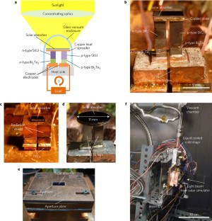
Concentrating solar power normally employs mechanical heat engines and is thus only used in large-scale power plants; however, it is compatible with inexpensive thermal storage, enabling electricity dispatchability. Concentrating solar thermoelectric generators (STEGs) have the advantage of replacing the mechanical power block with a solid-state heat engine based on the Seebeck effect, simplifying the system. The highest reported efficiency of STEGs so far is 5.2%. Here, we report experimental measurements of STEGs with a peak efficiency of 9.6% at an optically concentrated normal solar irradiance of 211 kW m −2 , and a system efficiency of 7.4% after considering optical concentration losses. The performance improvement is achieved by the use of segmented thermoelectric legs, a high-temperature spectrally selective solar absorber enabling stable vacuum operation with absorber temperatures up to 600 ∘ C, and combining optical and thermal concentration. Our work suggests that concentrating STEGs have the potential to become a promising alternative solar energy technology.
This is a preview of subscription content, access via your institution
Access options
Subscribe to this journal
Receive 12 digital issues and online access to articles
111,21 € per year
only 9,27 € per issue
Buy this article
- Purchase on Springer Link
- Instant access to full article PDF
Prices may be subject to local taxes which are calculated during checkout
Thermophotovoltaic efficiency of 40%

Kilowatt-scale solar hydrogen production system using a concentrated integrated photoelectrochemical device

Harvesting energy from sun, outer space, and soil
Jones-Albertus, R., Feldman, D., Fu, R., Horowitz, K. & Woodhouse, M. Technology advances needed for photovoltaics to achieve widespread grid price parity. Prog. Photovolt. Res. Appl. 24 , 1272–1283 (2015).
Article Google Scholar
Luque, A. & Hegedus, S. Handbook of Photovoltaic Science and Engineering (John Wiley, 2003).
Book Google Scholar
Green, M. A. Third Generation Photovoltaics: Advanced Solar Energy Conversion (Springer, 2003).
Google Scholar
John, A. & Duffie, W. A. B. Solar Engineering of Thermal Processes (Wiley, 2013).
Mills, D. Advances in solar thermal electricity technology. Sol. Energy 76 , 19–31 (2004).
Weinstein, L. A. et al. Concentrating solar power. Chem. Rev. 115 , 12797–12838 (2015).
Telkes, M. Solar thermoelectric generators. J. Appl. Phys. 25 , 765–777 (1954).
Goldsmid, H. J. Applications of Thermoelectricity (Methuen, 1960).
Kraemer, D. et al. High-performance flat-panel solar thermoelectric generators with high thermal concentration. Nat. Mater. 10 , 532–538 (2011).
McEnaney, K., Kraemer, D. & Chen, G. Direct heat-to-electricity conversion of solar energy. Annu. Rev. Heat Transfer 15 , 179–230 (2012).
McEnaney, K., Kraemer, D., Ren, Z. & Chen, G. Modeling of concentrating solar thermoelectric generators. J. Appl. Phys. 110 , 074502 (2011).
Venkatasubramanian, R., Siivola, E., Colpitts, T. & O’Quinn, B. Thin-film thermoelectric devices with high room-temperature figures of merit. Nature 413 , 597–602 (2001).
Harman, T. C., Taylor, P. J., Walsh, M. P. & Laforge, B. E. Quantum dot superlattice thermoelectric materials and devices. Science 297 , 2229–2232 (2002).
Dresselhaus, M. S. et al. New directions for low-dimensional thermoelectric materials. Adv. Mater. 19 , 1043–1053 (2007).
Poudel, B. et al. High-thermoelectric performance of nanostructured bismuth antimony telluride bulk alloys. Science 320 , 634–638 (2008).
Heremans, J. P. et al. Enhancement of thermoelectric efficiency in PbTe by distortion of the electronic density of states. Science 321 , 1457–1461 (2008).
Snyder, G. J. & Toberer, E. S. Complex thermoelectric materials. Nat. Mater. 7 , 105–114 (2008).
Biswas, K. et al. High-performance bulk thermoelectrics with all-scale hierarchical architectures. Nature 489 , 414–418 (2012).
Zhao, L.-D. et al. Ultralow thermal conductivity and high thermoelectric figure of merit in SnSe crystals. Nature 508 , 373–377 (2014).
Kim, S. I. et al. Dense dislocation arrays embedded in grain boundaries for high-performance bulk thermoelectrics. Science 348 , 109–114 (2015).
Beekman, M., Morelli, D. T. & Nolas, G. S. Better thermoelectrics through glass-like crystals. Nat. Mater. 14 , 1182–1185 (2015).
Zhao, L. et al. Ultrahigh power factor and thermoelectric performance in hole-doped single-crystal SnSe. Science 351 , 141–144 (2015).
Kraemer, D., McEnaney, K., Chiesa, M. & Chen, G. Modeling and optimization of solar thermoelectric generators for terrestrial applications. Sol. Energy 86 , 1338–1350 (2012).
Kim, H. S., Liu, W., Chen, G., Chu, C.-W. & Ren, Z. Relationship between thermoelectric figure of merit and energy conversion efficiency. Proc. Natl Acad. Sci. USA 112 , 8205–8210 (2015).
Snyder, G. J. Application of the compatibility factor to the design of segmented and cascaded thermoelectric generators. Appl. Phys. Lett. 84 , 2436 (2004).
Ioffe, A. F. Semiconductor Thermoelements and Thermo-electric Cooling (Infosearch, 1957).
Rowe, D. M. Thermoelectrics Handbook: Macro to Nano (Taylor & Francis Group, LLC, 2006).
El-Genk, M. S., Saber, H. H., Sakamoto, J. & Caillat, T. Life tests of a skutterudites thermoelectric unicouple (MAR-03). In 2003, Twenty-Second International Conference on Thermoelectrics – ICT 417–420 (IEEE, 2003); http://dx.doi.org/10.1109/ICT.2003.1287537
Guo, J. Q. et al. Development of skutterudite thermoelectric materials and modules. J. Electron. Mater. 41 , 1036–1042 (2012).
Muto, A., Yang, J., Poudel, B., Ren, Z. & Chen, G. Skutterudite unicouple characterization for energy harvesting applications. Adv. Energy Mater. 3 , 245–251 (2013).
Caillat, T. et al. Progress status of the development of high-efficiency segmented thermoelectric couples. In Nuclear and Emerging Technologies for Space (2012); http://www.lpi.usra.edu/meetings/nets2012/pdf/3077.pdf
Kraemer, D. et al. High thermoelectric conversion efficiency of MgAgSb-based material with hot-pressed contacts. Energy Environ. Sci. 8 , 1299–1308 (2015).
Cook, B. A. et al. High-performance three-stage cascade thermoelectric devices with 20% efficiency. J. Electron. Mater. 44 , 1936–1942 (2015).
Salvador, J. R. et al. Conversion efficiency of skutterudite-based thermoelectric modules. Phys. Chem. Chem. Phys. 16 , 12510–12520 (2014).
Goldsmid, H. J., Giutronich, J. E. & Kaila, M. M. Solar thermoelectric generation using bismuth telluride alloys. Sol. Energy 24 , 435–440 (1980).
Dent, C. L. & Cobble, M. H. A solar thermoelectric generator experiments and analysis. in 4th International Conference on Thermoelectric Energy Conversion 75–78 (IEEE, 1982).
Omer, S. Design optimization of thermoelectric devices for solar power generation. Sol. Energy Mater. Sol. Cells 53 , 67–82 (1998).
Amatya, R. & Ram, R. J. Solar thermoelectric generator for micropower applications. J. Electron. Mater. 39 , 1735–1740 (2010).
Baranowski, L. L., Snyder, G. J. & Toberer, E. S. Concentrated solar thermoelectric generators. Energy Environ. Sci. 5 , 9055–9067 (2012).
Kraemer, D., McEnaney, K., Cao, F., Ren, Z. & Chen, G. Accurate determination of the total hemispherical emittance and solar absorptance of opaque surfaces at elevated temperatures. Sol. Energy Mater. Sol. Cells 132 , 640–649 (2015).
Cao, F. et al. Enhanced thermal stability of W-Ni-Al2O3 cermet-based spectrally selective solar absorbers with tungsten infrared reflectors. Adv. Energy Mater. 5 , 1401042 (2015).
Brandt, R., Bird, C. & Neuer, G. Emissivity reference paints for high temperature applications. Measurement 41 , 731–736 (2008).
Coblentz, W. W. Harnessing heat from the sun. Sci. Am. 127 , 324 (1922).
Durst, T., Harris, L. B. & Goldsmid, H. J. Studies of a thermoelectric generator from tubular solar collectors. Sol. Energy 31 , 421–425 (1983).
NREL Concentrating Solar Power Research (2012); http://www.nrel.gov/csp
Domenicali, C. A. Irreversible thermodynamics of thermoelectric effects in inhomogeneous, anisotropic media. Phys. Rev. 92 , 877–881 (1953).
Liu, W. et al. Understanding of the contact of nanostructured thermoelectric n-type Bi2Te2.7Se0.3 legs for power generation applications. J. Mater. Chem. A 1 , 13093–13100 (2013).
Download references
Acknowledgements
This material is partially based upon work supported as part of the Sunshot Initiative funded by the US Department of Energy, Office of Energy Efficiency & Renewable Energy under Award Number: DE-EE0005806 (for device engineering) and based upon work supported as part of the Solid State Solar-Thermal Energy Conversion Center (S 3 TEC), an Energy Frontier Research Center funded by the US Department of Energy, Office of Science, Office of Basic Energy Sciences under Award Number: DE-SC0001299/DE-FG02-09ER46577 (for materials).
Author information
Authors and affiliations.
Department of Mechanical Engineering, Massachusetts Institute of Technology, Cambridge, Massachusetts 02139, USA
Daniel Kraemer, Kenneth McEnaney, Lee A. Weinstein, James Loomis & Gang Chen
Department of Physics and TcSUH, University of Houston, Houston, Texas 77204, USA
Qing Jie, Feng Cao, Weishu Liu & Zhifeng Ren
You can also search for this author in PubMed Google Scholar
Contributions
D.K. carried out modelling and simulation, CSTEG fabrication and experiments, and prepared the manuscript; Q.J. and W.L. fabricated the thermoelectric and contact materials; K.M. contributed to CSTEG fabrication and experiments and device modelling; F.C. fabricated spectrally selective solar absorbers; L.A.W. contributed to manuscript preparation and CSTEG fabrication and experiments; J.L. contributed to CSTEG fabrication and experiments; Z.R. directed research at UH; G.C. directed research at MIT and contributed to the manuscript preparation.
Corresponding authors
Correspondence to Zhifeng Ren or Gang Chen .
Ethics declarations
Competing interests.
The authors declare no competing financial interests.
Supplementary information
Supplementary information.
Supplementary Figures 110, Supplementary Tables 1 and 2, Supplementary Methods and Supplementary References (PDF 1841 kb)
Rights and permissions
Reprints and permissions
About this article
Cite this article.
Kraemer, D., Jie, Q., McEnaney, K. et al. Concentrating solar thermoelectric generators with a peak efficiency of 7.4%. Nat Energy 1 , 16153 (2016). https://doi.org/10.1038/nenergy.2016.153
Download citation
Received : 12 March 2016
Accepted : 24 August 2016
Published : 19 September 2016
DOI : https://doi.org/10.1038/nenergy.2016.153
Share this article
Anyone you share the following link with will be able to read this content:
Sorry, a shareable link is not currently available for this article.
Provided by the Springer Nature SharedIt content-sharing initiative
This article is cited by
Fabrication and thermoelectric conversion of thermoelectric concrete brick with buried unileg n-type camno3 thermoelectric module inside.
- Keerati Maneesai
- Sunisar Khammahong
- Chesta Ruttanapun
Scientific Reports (2023)
Screening metal diffusion barriers for thermoelectric Bi0.5Sb1.5Te3
- Yanzhong Pei
Science China Materials (2023)
Liquid-based high-temperature receiver technologies for next-generation concentrating solar power: A review of challenges and potential solutions
- Wenquan Tao
Frontiers in Energy (2023)
Review of regulation techniques of asphalt pavement high temperature for climate change adaptation
- Zhenlong Gong
- Letao Zhang
- Yinghao Miao
Journal of Infrastructure Preservation and Resilience (2022)
Enhanced electrical outputs of thin-film solar thermoelectric generator with optimized metal/dielectric multilayered solar selective absorber
- Zheng-Yong Wang
Applied Physics A (2022)
Quick links
- Explore articles by subject
- Guide to authors
- Editorial policies
Sign up for the Nature Briefing newsletter — what matters in science, free to your inbox daily.

- Search Menu
- Advanced Articles
- Editor's Choice
- Author Guidelines
- Publish with us
- Submission Site
- Open Access
- Self-Archiving Policy
- About Clean Energy
- About the National Institute of Clean and Low-Carbon Energy
- Editorial Board
- Instructions for Reviewers
- Advertising & Corporate Services
- Journals Career Network
- Journals on Oxford Academic
- Books on Oxford Academic

Article Contents
Introduction, 1 hpvteg hybrid system description, 2 materials and methods, 3 experimental results and discussion, 4 economic analysis, 5 conclusions and future research recommendations, acknowledgements, author contributions, conflict of interest statement, data availability.
- < Previous
Experimental study on hybridization of a PV–TEG system for electrical performance enhancement using heat exchangers, energy, exergy and economic levelized cost of energy (LCOE) analysis
- Article contents
- Figures & tables
- Supplementary Data
Mohammed A Qasim, Vladimir I Velkin, Sergey E Shcheklein, Experimental study on hybridization of a PV–TEG system for electrical performance enhancement using heat exchangers, energy, exergy and economic levelized cost of energy (LCOE) analysis, Clean Energy , Volume 7, Issue 4, August 2023, Pages 808–823, https://doi.org/10.1093/ce/zkad023
- Permissions Icon Permissions
The concept of employing thermoelectric generators (TEGs) to recover energy from waste heat has gained popularity, with applications that range from milliwatt to kilowatt levels of output power. In this study, a hybrid photovoltaic panel and thermoelectric generator (HPVTEG) system consisting of an integrated heat exchanger, a commercial polycrystalline silicon photovoltaic (PV) panel and a commercial bismuth telluride TEG was proposed. Here, TE components can be used to cool PV modules, increasing their output power via the Seebeck effect. The main finding is that the hybrid system has a reduced average temperature of 16.01°C. The average power of the stand-alone PV panel is 28.06 W, but that of the HPVTEG system is 32.76 W, which is an increase of 4.7 W. The conversion efficiency and power of the hybrid system increased by 16.7% and 16.4%, respectively, compared with a stand-alone PV panel. The HPVTEG system achieved an average exergy efficiency of 12.79% compared with 10.98% for a stand-alone PV panel. According to the calculation results, the levelized cost of energy (LCOE) of the stand-alone PV panel can range from 0.06741 to 0.10251 US$/kWh depending on how many days it is in operation, while the LCOE of the HPVTEG system can range from 0.06681 to 0.10160 US$/kWh.

The need for energy is growing. Since natural resources are becoming scarcer, it is crucial to provide clean, reusable and ecologically friendly energy. The largest source of renewable energy, which can be directly transformed from light and heat to electricity, is solar energy [ 1–3 ]. Compared with a stand-alone photovoltaic (PV) system, combined PV and thermoelectric generator (TEG) systems have received considerable attention over the past 10 years and have been shown to be an excellent way to utilize waste solar heat [ 3–6 ]. Using a temperature differential between the back of the PV panel and the TEG cold junction, the Seebeck effect allows TEG modules to directly convert waste thermal energy into electricity. TEGs have several advantages since the heat supply is constant, they do not make noise, they are clean and they are compatible with PV systems. Furthermore, they can function for many years [ 7 , 8 ]. However, it is probable that the hybrid photovoltaic panel and thermoelectric generator (HPVTEG) efficiency is lower than that of PV systems alone [ 9 ]. Increased temperature differences will increase the efficiency of the TEG but reduce PV efficiency. Therefore, the connection between PV and TEG technology is complicated, which affects the performance of such systems [ 10 ].
Zhang et al. increased the open-circuit voltage and doubled energy harvesting. They developed a combination of polymer solar cells with thermoelectric (TE) modules [ 11 ]. Kil et al. concentrated on developing a PV/TE hybrid generator with a single junction. Their system used a GaAs-based solar cell and a conventional TE module. They found that the conversion efficiency of this hybrid system was 23.2% compared with 22.5% for a single PV cell. This improvement was ~3% at a solar intensity of 50 suns [ 12 ].
Rajaee et al. conducted studies on a system that included PV cells, TEGs (TEGs), nanofluids and phase-change materials. They found that the total electrical efficiency of the system could reach 15.8%. Moreover, they were able to increase the overall output by 42% [ 13 ]. Fini et al. conducted a 24-h analysis that involved experimental testing, mathematical modelling and finite-element simulation of a HPVTEG system using water-cooled heat exchangers that had been proposed to extract more power from the system. They found that the average maximum PV panel temperature in both the experimental measurements and the simulations of the hybrid system was 44.2°C at maximum irradiation, while it was 57.1°C for a reference PV panel. Furthermore, they found that the efficiency of a pure PV panel was 13.82% while that of its hybrid systems was 15.6% [ 14 ].
Mahmoudinezhad et al. tested the performance of PV, TEG and HPVTEG systems using a spectrum beam splitter. According to the results of their analysis, the system that used only TEGs generated more power than the TEG in the hybrid system because it made better use of the whole spectrum of energy available to it. While the efficiency of the TEG component decreased, the total efficiency of the hybrid system improved due to the increased PV efficiency. The hybrid system produced more power than either the PV or TEG systems individually [ 15 ].
Lorenzi et al. designed a Bi 2 Te 3 TEG device for hybridization with three distinct panels. These were amorphous silicon (a-Si), gallium indium phosphide (GaInP) and perovskite PV panels. At an intensity of 5 suns and a panel temperature of 340 K, the perovskite panel had the greatest efficiency improvement among three HPVTEG systems. Then, they experimentally constructed a perovskite HPVTEG model. Their tests revealed a change in efficiency from 16.8% to 19.5%—a 16.07% improvement [ 5 ].
Babu et al. also used the MATLAB ® /Simulink ® environment to do a theoretical study of a non-concentrating hybrid HPVTEG system. This hybrid system was 6% more efficient overall and could produce 5% more energy [ 16 ]. Shatar et al. considered the load requirements of an indoor farm to design an unconcentrated PV–TEG hybrid system. The performance of the hybrid system was evaluated during 3 months of testing in Malaysia. The planned system was proven to be able to accommodate an additional load while also providing enough power to service its intended load [ 17 ].
Van Sark did direct coupling to combine TE modules with solar cells to create a hybrid HPVTEG system that achieved improved electrical performance [ 18 ]. This technology was offered as an efficient thermal management strategy for PV cells. Two case studies were provided from Utrecht, The Netherlands and Malaga, Spain. The results also indicated that the energy of Malaga and Utrecht could increase by ~14.7% and ~11%, respectively, using the annual irradiance and temperature profiles of these cities. However, this study overlooked radiation losses and the idealized model overstated the results for real HPVTEG systems by ~10% [ 18 ].
Ko et al. used MATLAB ® software to quantitatively examine the transient behaviour of a HPVTEG system incorporated into a building in combination with phase-change materials (PCMs). They investigated the impact of the PCM layer thickness and melting point on the HPVTEG efficiency. According to their findings, the hybrid system was 1.09% more efficient than a PV system alone, with 0.18% coming from TEGs and 0.91% from PVs. Furthermore, the proposed system produced 0.91% more energy in spring, 1.32% more in summer, 2.25% more in autumn and 3.16% more in winter. It was suggested that the hybrid system might possibly produce 4.47% more power than a single PV system when TEGs with higher figure of merit were employed [ 19 ].
Beeri et al. presented experimental and theoretical data for a combined HPVTEG system to convert concentrated sunlight, with a factor of X of ≤300, into electricity. These results demonstrate that when the X-value and system temperature were increased, the efficiency of the PV cell decreased and that of the TEG increased. As a result, the direct electrical contribution of the TEG began to predominate in the overall system, reaching a 20% power contribution at an X-value of 290. Efficiency changed from 28.95% to 30.53% with an improvement of 5.45% at a concentration factor of 205. Using more sophisticated PV cells and TE materials, it was demonstrated that the hybrid system may exceed 50% overall efficiency [ 20 ].
Khan et al. demonstrated an experimental PV–TEG system. A 10-W polycrystalline silicon panel with 10 bismuth telluride TEG modules was mounted on the back of the panel to recover and convert waste heat into usable electrical energy, while simultaneously cooling the PV cells. The results showed that this hybrid system achieved increased output power and conversion efficiency values for PV modules. In the hybrid system, the operating temperature of the PV module decreased by 5.5%, from 55°C to 52°C. Compared with a straightforward PV system, the total output power of the hybrid system increased from 8.78 to 10.84 W—a 19% increase. Furthermore, the efficiency of the HPVTEG system increased from 11.6% to 14%—a total improvement of 17% [ 21 ].
Li et al. showed inconsistency of TE load resistance for PV–TE modules from a theoretical perspective. Two types of PV cells were employed to build and test a model PV–TE. Under various working conditions for a TE module, a TE in the PV–TE and a PV–TE, the maximum load resistance of each TE was examined. The efficiency of crystalline silicon alone was 9.5% and increased to 11.07% in a hybrid system with a TE load resistance of 0.75 and a figure of merit of 0.0085/K. The efficiency of GaAs alone was 21.91% and this increased to 22.94% in the hybrid mode when the TE load resistance was 1.60 and the figure of merit was 0.0022/K [ 22 ].
Zhang et al. used 3D numerical modelling to calculate the potential and characteristics of an integrated system consisting of new perovskite solar cells and TE modules. They found that the temperature coefficient of the perovskite solar cell was <2%. Due to such a reduced temperature coefficient, the efficiency of the perovskite solar cell–TEG hybrid system was 18.6%, while that of a pure perovskite solar cell was 17.8%, making it a good alternative in a HPVTEG system. The heat can be changed, and thus the required bulk TEG material may be reduced, leading to significant cost savings for a hybrid system [ 23 ].
Cui et al. experimentally utilized a PCM to develop a unique PV–PCM–TE hybrid system to maintain system function at an optimal temperature. The temperature, efficiency and output power of the hybrid system were compared with those of a stand-alone PV system under identical conditions. The effects of the optical concentration ratio and cooling approach on the conversion efficiency of the hybrid system were experimentally explored. According to the results, the hybrid PV–PCM–TE system had an efficiency of 13.45%, compared with that of a stand-alone system of 13.43%. The study indicated that such a hybrid system has good potential for full-spectrum conversion of solar energy [ 24 ].
Generally, previous studies do not consider some issues. Most HPVTEG systems link many TE modules in a series and parallel array to achieve the necessary power level. The uniform temperature distribution of the TE modules, the influence of the pressure distribution on the assembly, the thermal contact between the modules and the heat exchangers, and the thermal bridge between the heat exchangers and the PV panel were not given much attention. Additionally, the issues of concentrated and non-concentrated solar irradiation techniques were given little consideration in HPVTEG systems. For non-concentrated HPVTEG systems, the electrical performance of PVs and the gradient temperature for TEGs are low, and most of the electricity is produced by the PVs. However, for concentrated HPVTEG systems, the operating temperature of the PV system increases, sometimes to levels of >100°C, significantly reducing its performance. This led to high temperature gradients for TEGs and increased electricity production.
Therefore, the creation of a hybrid system that balances the performance of solar panels and TEGs, with appropriate electrical connections and assembly of TEG modules to obtain the appropriate voltage, is extremely important, where the modules are attached to the back of generic PV panels. In this work, a TEG configuration test method was used to measure and analyse data obtained from TEGs, one of which was highly efficient in the proposed system. In addition, a HPVTEG system was fabricated using an experimental design for the Iraqi climate using analysis of energy, exergy and economic levelized cost of energy (LCOE). The overall objective of the current research is to quantify the performance of this system and its associated parameters with the goal of enhancing the conversion efficiency and heat recovery of a PV panel in a hybridized system (HPVTEG) for comparison with a stand-alone PV panel.
A hybrid HPVTEG system paired with water-cooled heat exchangers was fabricated to study the heat recovery and cooling of a PV panel and capture of a greater portion of the solar spectrum. This is one option to improve the efficiency of PV technologies [ 25–28 ]. Fig. 1 shows the configuration of the hybrid system, which consists of two solar panels mounted on an iron structure that is tilted at a 33° angle towards the south.

The proposed system. (a) Experimental set-up system with measurement devices and (b) schematic diagram of the experimental system.
1.1 Main and subsystem components
1.1.1 pv panel.
PVs play a crucial part in determining the final output of the system. Two polycrystalline PV panels, manufactured by Fortuner, were chosen for this experiment; they have a nominal maximum power of 50 W, a power coefficient of 0.004/K and an efficiency of 14.51% under standard test conditions (STC): sea level air mass (AM) = 1.5, 1000 W/m 2 cell temperature, 25°C. Table 1 highlights the properties of the PV panel [ 29 ].
PV panel properties
1.1.2 TEG module
A semiconductor-based device, known as a TEG, serves as a tiny generator using the Seebeck effect when a temperature differential is applied to its surfaces. TEG modules made from bismuth telluride (Bi 2 Te 3 ) are employed to produce the required power. These modules were created specifically for power generation. Table 2 lists the characteristics of the TEG module [ 7 , 15 ].
Thermoelectric module properties
1.1.3 Poly(methyl methacrylate)
Generally, heat exchangers or the TE modules themselves are taken into account when optimizing TEGs [ 30 , 31 ]. However, since poor contact or a thermal bridge can undermine the performance of a perfect generator, consideration of the entire assembly of the TEG is crucial. This is to control the impact of the pressure distribution on the assembly, as well as the thermal contact resistance between the modules, the heat exchangers and the thermal bridge between the exchangers. Poly(methyl methacrylate) (PMMA), an acrylic, was considered with dimensions of 142.5 × 455 mm 2 . It has specific qualities that make it a good material for use in a variety of applications. This thermoplastic is ideal for joining TEG pieces to aluminium sheets to sandwich a PV module, due to its excellent thermal insulation properties and high resistance to temperature changes [ 32 ].
1.1.4 Heat exchanger cooling
An aluminium water block was utilized to dissipate heat from the cold side of the TEG and rear PV panel. The dimensions of each piece were 40 × 240 × 10 mm 3 . The parameters of the heat exchanger and some characteristics of water are shown in Table 3 , where these values were extracted by numerical analysis during our earlier work [ 33 ].
Heat exchanger parameters and water properties
1.1.5 Mathematical expressions and governing equations
In this section, the HPVTEG system governing equations, as well as its energy and exergy analyses, are considered.
1.2 Computation of energy
1.2.1 solar pv subsystem.
The reduction in operating temperature (caused by the TE device) is the main source of the performance improvement for solar cells integrated into a HPVTEG configuration. Therefore, it is necessary to describe the performance parameters of the cell with respect to temperature to determine the source of improvement [ 34 ]. Using Equation (1), it is possible to determine the PV cell efficiency η m p p ( G , T p v ) for an operating temperature T p v [ 35 ]:
where T r e f represents the reference air temperature and G is the incident solar irradiance. The temperature efficiency coefficient, often given by the cell manufacturer, is denoted by β , while η m p p ( G , T r e f ) represents the PV cell efficiency at STC.
After defining the PV conversion efficiency η m p p ( G , T p v ) , Equation (2) may be used to calculate the PV cell power output at a previously determined temperature T p v [ 36 ]:
where A is the solar-facing frontal area of the PV cell.
1.2.2 TE subsystem
Each TEG thermocouple has p- and n-junctions (legs). Thermal transmission losses, as well as electrical and thermal contact resistances, are neglected. At steady state, the power is absorbed at the hot side of the TEG module and the power is discharged at the cold junction [ 37 ], as follows:
In Equations (3) and (4), the first terms on the left-hand side indicate Peltier heat in power transmission, whereas the second and third terms imply Joule and Fourier heat in power transmission. Internal resistance ( R ) and thermal conductance ( K ) are expressed as [ 38 ]:
where α is the Seebeck coefficient; ρ p and ρ n are the densities of the legs; l T E G l is the TEG leg length; and A p and A n are the cross-sectional areas of the TEG legs, which are equal.
Using the difference P h − P c , the output power of the system may alternatively be represented as current and load resistance, R L :
Additionally, the current and Seebeck electromotive force (e.m.f.) can be calculated as:
Combining Equations (3), (4), (8) and (10), the efficiency of the TEG module can be expressed as Equation (11) [ 39 ]:
where β = R l R , Z p , n = α 2 ρ k and η c = T h − T c T h . The maximum efficiency occurs at β = R l R = ( 1 + Z T ) 0.5 , where T h and T c are averaged to yield T :
1.2.3 HPVTEG system
A hybrid system was developed that combined PV and TEG modules with four wires in parallel for an isolated load, where the energy-harvesting process was executed separately. This system is illustrated in Fig. 2 as its equivalent electrical circuit.

Circuit diagram for the HPVTEG system.
The solar energy, Q , illuminates the PV cell, which produces electricity, p p v . Heat is produced that is not converted to electricity by the PV cell, which is then transferred to the hot side of the TEGs, transforming it into extra electrical power p t e g that is removed from the system on the cold side of the TEGs. Equations (13) and (14) provide the total system electrical power output p t o t and efficiency η t o t [ 40 ]:
where Q is the incident solar irradiance input energy, which is equal to G ⋅ A , where G and A are the Sun intensity and solar module area.
1.2.4 Exergy modelling
This section presents a detailed exergy analysis of the HPVTEG system under investigation. Exergy analysis is a helpful technique for contrasting the actual and desired performance of the system. By lowering the exergy destruction parameters, the performance of the device is enhanced. Calculating exergy efficiency is as follows [ 41 ]:
where E x t o t is the total quantity of exergy obtained and E x i n is the input exergy of the system; they can be obtained by using [ 41 ]:
where G is the solar radiation, A PV is the panel aperture area, T amb is the surrounding air temperature and T s is the temperature of the energy source (the Sun). The exergy acquired from the water, PV and TEGs is denoted as E x t h , Ex PV and Ex TEG , and they can be obtained by using [ 42 ]:
In these equations, m ˙ w represents the mass flow rate of a coolant fluid and c P w is its heat capacity. T o u t w and T i n w are the water inlet and outlet temperatures. The PV reference efficiency is denoted by η ref , while the PV efficiency temperature coefficient is β r e f and the PV temperature is T p v . P T E G and P c represent the output power and the power absorbed by the TEGs, respectively. P c can be obtained by using [ 42 ]:
where n is the number of thermocouples of the TEG, α is the Seebeck coefficient, and I , R and K are the electric current, electrical resistance and thermal conductivity of the TEGs, respectively. The parameters of the PV panel and the TEG found in [ 43–47 ] and those of the heat exchanger are given in Section 1.1.4 [Heat exchanger cooling].
2.1 Experimental set-up
This section presents the techniques and materials required to fabricate the experimental set-up and the techniques to record the experimental data.
2.1.1 TE module
It is necessary to take advantage of the heat produced during PV cell operation and ensure that the hybrid system performance is better than that of the non-hybrid systems. Two electrical configurations were considered for TEGs.
2.1.2 Experiment 1: Configuration-1-SP
Series and parallel array configurations (Configuration-1-SP) with 20 TEGs are suggested. This configuration used two groups of 10 TEG modules connected in series. Then, the two groups were connected in parallel. Fig. 3 shows an equivalent circuit for this configuration.

Equivalent circuit of the Configuration-1-SP thermoelectric generator.
2.1.3 Experiment 2: Configuration-2-SP
In Configuration-2-SP, groups with two TEG modules are connected in series. Then, 10 groups were connected in parallel. Fig. 4 shows the equivalent circuit of this configuration.

Equivalent circuit of the Configuration-2-SP thermoelectric generator.
Then Configuration-1-SP was considered in this work. This configuration is used to make the internal resistance, R i n , approximately equal to the external load, to improve electrical performance, since the maximum power can be achieved when ( R in is R Load).
2.1.4 Assembly of the HPVTEG system
As shown in Fig. 1 , the assembly used TEG modules attached to a sheet of aluminium 6061, affixed to the rear of the PV panel with thermal paste. Four heat exchangers were attached underneath each group of five TEG modules. These heat sinks were attached to the TEG modules using thermal paste to improve heat transfer. Finally, thermoplastic PMMA was used for joining the TEG to the PV module, fixing it to the frame. Silicon water tubes were used to connect the heat sinks to a tap water source. Tap water was selected as a cooling fluid because it is readily available in homes and there is no need for a circulation pump. It is quite suitable for heat transfer because of its low cost and high heat capacity. The water flow rate was an approximately constant (2.56 L/min) at ~23°C throughout the experiment. The water circulates through the heat exchanger and is returned to the homes.
The temperatures of the PV cell and the TEG hot side that provides the heat input were considered to be equal throughout the experiment. The temperatures of the hot and cold sides of the TEGs as well as the inlet and outlet water temperatures of their corresponding heat sinks were measured using K-type thermocouples. The operating temperature of the solar panel was measured using a separate thermocouple attached to the rear of the PV panel. Measured values from multiple thermocouples were transmitted directly to a microcontroller and saved on a Secure Digital (SD) memory card.
The approach used in this study is unique and simple. In most studies, the TEGs are individually fixed to the rear side of the panel. In the current study, we attached the TEGs as groups with an appropriate electrical configuration for an individual panel.
The cooling mechanism employed in this study also allows the back of the PV panel to be cooled by the TEG panels, i.e. the cooling block water, since the TEG panels do not cover the entire back surface of the solar panel. The complete experimental set-up is provided in Fig. 5 .

Overview of the experimental set-up of the HPVTEG system. (a) Final experimental set-up with Configuration-1-SP and (b) schematic of the experimental set-up.
The experimental results of the TEG and hybrid HPVTEG systems are discussed in this section, as well as the results of the hybrid system compared with a stand-alone PV panel operated under the same conditions. The experiments were carried out in July, during the summer, in Baghdad, Iraq. The geographical coordinates were latitude 33.313 o N and longitude 44.331 o E. Testing was carried out from 9:00 h to 16:30 h. The measurements were made at ~15-minute intervals.
3.1 Environmental impact and analysis
The radiation profile, relative humidity, wind speed and air temperature during the testing period are shown in Figs 6 and 7 , drawn using Origin software [ 48 ] to develop curves for radiation and temperature. The findings show that solar irradiance increased steadily over time. The average solar irradiance of 783.18 W/m 2 peaked at noon with an instantaneous value of 963.07 W/m 2 and began to decline thereafter. The averages of outside temperature, relative humidity and wind speed were 42.61°C, 11.70 and 1.88 m/s, respectively. The wind velocity varied from ~1.0 to 2.2 m/s.

Solar radiation and air temperature during the experimental runtime.

Relative humidity and wind speed during the experiments.
3.2 Temperature effects
3.2.1 analysis of the teg temperatures profile.
Since the air temperature peaked at 13:00 h, the hot- and cold-side temperatures, Δ T , similarly peaked at this time and then fell, as illustrated in Fig. 8 . The TEG hot side ( T h ) showed high and low temperatures of 51.49°C and 35.08°C, respectively, with an average temperature of 44.97°C. When the experiment first began, T c was low on the cold side. After noon, it gradually decreased, as heat accumulated in the water and reached an equilibrium. Low and high cold-side temperatures were 24.88°C and 27.55°C, respectively, with an average temperature of 26.71°C. The temperature difference ( Δ T ) between the hot and cold sides of the ranged between 10.21°C and 24.06°C, respectively, with an average temperature difference of 18.25°C. These temperatures were measured using thermocouples and a microcontroller to provide more precise results.

Hot-side and cold-side temperatures of the TEGs, with temperature differentials at various times.
3.2.2 HPVTEG system temperature profiles
The PV panel temperature is a crucial component since it determines the performance of the system. Fig. 9 displays a temperature–time curve for HPVTEG and stand-alone systems. Each PV panel had five K-type thermocouples installed in various places to provide measurements every 15 minutes.

PV modified and stand-alone PV panel temperatures as a function of time.
According to Fig. 9 , the temperatures of the HPVTEG system and stand-alone PV panel increased throughout the day until they reached a maximum at 13:00 h. The maximum, minimum and average temperatures of the HPVTEG system during the testing were 51.49°C, 35.08°C and 44.97°C, and 67.76°C, 52.86°C and 60.98°C for the stand-alone panel, respectively. This represents a 16.01°C cooler operating temperature for the HPVTEG system compared with a stand-alone module.
This reduction is significant, especially considering that this process uses little circulation water to remove heat from the cold side of the TEGs and no electricity is used to cool the PV module. As a result, this system can be used in regions with readily accessible tap water or as geothermal technology in areas without water.
3.2.3 Heat exchangers
The input and output water temperature profiles of the four heat exchangers are shown in Fig. 10 . The input water temperatures were approximately constant, at ~23°C, during the experiment. The output water temperature was greater than its input temperature, as shown in this figure, as a result of increased TEG cold-side temperatures, which averaged 25.92°C with a maximum value of 26.79°C. The output water temperature peaked at 13:15 h, at the same time as the cold-side TEG temperature, but there was a 15-minute lag in the temperature of the PV panel, since its cooling water was slower to lose heat.

Input and output temperatures of a heat exchanger as a function of time.
3.3 Electrical energy assessment
3.3.1 teg configuration analysis.
Fig. 11 shows the results of power and efficiency from the two TEG electrical configurations. Since the temperature was the same for each set-up during the experiment, the power extracted and efficiency varied, with Configuration-1-SP achieving the highest performance. This came from the type of TEG electrical connections. According to the findings, the average output power and efficiency of Configuration-1-SP were 1.24 W and 0.51 , while they were 0.20 W and 0.08% for Configuration-2-SP, respectively.

Electrical configurations of TEGs. (a) Output power versus time; (b) efficiency versus time.
3.3.2 HPVTEG system
Figs 12 and 13 display the output power and efficiency values for the HPVTEG system and stand-alone panel. Statistics show that at 12:00 h, the maximum power output of the HPVTEG system was 39.97 W, while the peak power of the stand-alone panel was 33.99 W. However, since the stand-alone panel operated at a relatively high temperature, it suffered a power reduction. Throughout the tests, the HPVTEG system and the stand-alone panel average power values were 32.76 and 28.06 W, respectively. The HPVTEG system shows an average improvement of 16.7 .

Output power of the HPVTEG and stand-alone PV systems.

Electrical efficiency versus time for the HPVTEG and stand-alone PV systems.
Until midday, the intensity of the solar radiation helps to raise the power extracted from both the HPVTEG system and the stand-alone panel. However, the electrical efficiency of the HPVTEG system and the stand-alone panel began to decrease as a result of the increase in operation temperature, and then after noon the electrical efficiency returned to increase as a result of the decrease in the temperature of the HPVTEG system and the stand-alone panel as shown in Fig. 13 . The HPVTEG system had an average efficiency of 13.86% compared with the PV stand-alone panel, at 11.90%. This is because of the high temperatures that were recorded throughout the period of the experiment for the stand-alone PV panel. The electrical efficiency of the HPVTEG system was improved by ~ 16.4
Since the hybrid system used TEGs and heat exchangers, this efficiency improvement is very significant. This resulted in a lower panel operating temperature that allowed more power extraction from the TEGs.
3.3.3 Exergy efficiency assessment analysis
Fig. 14 shows the exergy efficiency results of the HPVTEG system and stand-alone PV panel. The power output of a power plant has a negative impact on its energy efficiency. The profiles for the energy efficiency for the two systems can thus be observed from the data, since they are similar to those for the electrical efficiency.

Exergy efficiency of stand-alone and HPVTEG systems versus time.
The exergy efficiency decreased from the beginning of the experiment until about 13:00 h, when it began to increase due to increased PV module temperatures. The exergy of the HPVTEG system was consistently greater throughout the testing, indicating that the suggested hybrid system can be used to control the temperature of the PV module.
As a result, the average exergy efficiencies for the HPVTEG system and the stand-alone PV panel, respectively, were 12.79% and 10.98%. It is clear from the data that the modified PV panel had a higher exergy efficiency.
3.3.4 Measurement error analysis
Measurement accuracy, test system design specifics and human error affect the accuracy of experimental findings. Table 4 , derived from measuring equipment, lists experimental errors that could exist in the parameters utilized.
Measurement uncertainties of various devices
Using previously published error analysis methodology [ 49–52 ], the total percentage of uncertainty u ( z ) can be calculated using Equation (22):
where Z , Δ y 1 , Δ y 2 , . . . Δ y n are dependent variables of various inputs, in which potential errors may exist. The total percentage of uncertainty in the proposed system used in these experiments is 3.87%, which is considered allowable in the context of a study such as this.
3.3.5 Examining the system in relation to other researches
Table 5 compares our findings with the research discussed above and other studies. Generally, the results are superior or equivalent to the systems described in prior investigations.
Comparison of the current system to previous studies
An LCOE strategy was employed to analyse energy production costs for the proposed system. This strategy is often used to evaluate the economic feasibility of renewable-energy facilities. It indicates the costs in a way that compares various power producing methods on a normalized basis [ 53 , 54 ]. The LCOE is described as the lowest cost at which the energy produced must be sold to financially break even during the life of the project [ 55 , 56 ]. Additionally, it assesses the average overall cost of building and operating a power plant over the course of its lifetime divided by the total amount of energy produced during that period. The mathematical formulation of the LCOE is [ 57 ]:
where the investing cost is C inv , n is the plant lifetime, CRF is the capital recovery factor, C O&M represents the yearly operation and maintenance expense, CELF is the constant-escalation laterization factor, i eff represents the effective discount rate and r n is the nominal escalation rate.
The main production expenditures in the proposed HPVTEG system are heat exchangers and TEGs, requiring two sets of TEGs at a price of US$15.2, and four heat exchangers at a price of US$2, based on year 2022 data. In general, the HPVTEG system and associated equipment cost US$71.2 with a solar panel price of US$54.
This study considered two possibilities for the energy produced by the power plant:
(i) The first case entails circumstances in which the power plant operates all year with no bad weather. Every day of the year is used to produce electricity in this case.
(ii) The second case also considers a situation with favourable weather for only a portion of the year, such as that in Iraq. This considers Iraq’s 8-month summer season, or 240 days, as productive in this case.
Assumptions were made that the panel would be exposed to solar radiation for 10 h a day for 365 and 240 days, respectively. The energy output from the HPVTEG power plant and the stand-alone panel in the first and second cases was (120.09 kWh, 78.96 kWh) and (102.42 kWh and 67.34 kWh), respectively. Then we used the information in Table 6 to determine the LCOE of both systems.
Calculation of LCOE parameters
According to the calculations, the HPVTEG system LCOE in the first case, with 365 days of production, was 0.06681 US$/kWh as opposed to 0.06741 US$/kWh for the stand-alone PV panel. Furthermore, the HPVTEG hybrid system showed an LCOE of 0.10160 US$/kWh for the second case with 240 days of production compared with 0.10251 US$/kWh for the stand-alone PV panel.
These data clearly show that the HPVTEG hybrid system outperformed the stand-alone PV panel in terms of cost under both scenarios, despite the additional costs associated with integrating the TEG with the PV panel. This implies that adding the suggested TEG mechanism to a PV module will increase its cost-effectiveness in addition to improving its electrical and exergy efficiency.
TEGs and heat exchangers were used to improve the functionality and lower the operating temperature of a PV panel while using the whole solar spectrum in an HPVTEG system. Current research enables the following conclusions to be drawn:
(i) Efficiency and output power are significantly improved using the HPVTEG system. This results from the use of water by the HPVTEG system as a cooling medium, rather than unstable and variable cooling sources. This system is independent, economical and has no complicated mechanisms.
(ii) The use of the PMMA board serves three functions: cohesion, good pressure distribution and insulation. This led to an improvement in the power of the TEG modules.
(iii) There was an average temperature difference ( Δ T ) of 18.25 °C between the hot and cold sides of the TEGs.
(iv) During experimentation, the average HPVTEG system temperature was 44.97 °C compared with 60.98 °C for the stand-alone PV panel. Therefore, the use of the TEG module with cooling resulted in an average temperature that was 16.01°C lower for the HPVTEG system.
(v) During the experiments, the average water temperature at the exit of the heat exchanger was 25.92°C.
(vi) Among the TEG configurations, the average power and efficiency for Configuration-1-SP were 1.24 W and 0.51 , whereas those for Configuration-2-SP were 0.20 W and 0.08%, respectively.
(vii) The average power output for the HPVTEG system was 32.76 W, whereas that of the stand-alone PV panel was 28.06 W. The increase in electricity generation is 4.7 W in total—an average improvement of 16.7 .
(viii) The average efficiency of the HPVTEG system was 13.86%, while the efficiency for the stand-alone PV panel was 11.90%. The increase in electricity generation is 1.96% in total—an improvement of ~16.4%.
(ix) There is an average difference of 1.81% in the exergy efficiency between the stand-alone PV panel and the HPVTEG system.
(x) Financially, in the first scenario (365 days of production), the HPVTEG system had an LCOE equivalent to 0.06681 US$/kWh compared with 0.06741 US$/kWh for the stand-alone PV panel. Furthermore, the HPVTEG system showed an LCOE of 0.10160 US$/kWh for the second case (240 days of production) compared with 0.10251 US$/kWh for the stand-alone PV panel.
In practice, the HPVTEG mechanism has been shown to be technologically and economically better. The proposed hybrid mechanism shows the lowest LCOE due to its high efficiency, even if its modifications come at an additional cost.
According to the findings of this study, it is possible to use the suggested cooling mechanism and the TEG module in hot climates, such as Iraq, to improve the performance of solar PV panels and produce more power.
More TEGs might be used to cover the back of the solar panel, but future research should also consider the financial implications of this action. Future research may look towards using a nanofluid rather than water to dissipate more heat from the PV panel.
The research funding from the Ministry of Science and Higher Education of the Russian Federation (Ural Federal University Program of Development within the Priority-2030 Program) is gratefully acknowledged (grant number FEUZ-2022-0031). This research project received no external funding.
Conceptualization, M.A.Q. and V.I.V.; methodology, M.A.Q.; software, M.A.Q.; validation, M.A.Q., S.E.S. and V.I.V.; formal analysis, M.A.Q. and V.I.V.; investigation, M.A.Q.; resources, S.E.S. and M.A.Q.; data curation, M.A.Q. and S.E.S.; writing—original draft preparation, M.A.Q.; writing—review and editing, M.A.Q.; visualization, M.A.Q., supervision, V.I.V.; project administration, M.A.Q.; funding acquisition, M.A.Q. All authors have read and agreed to the published version of the manuscript.
The authors declare that they have no conflicts of interest that could have affected the design and conduct of the study, its conclusion or technical implications.
All important data are included in the manuscript.
Li G , Zhao X , Ji J. Conceptual development of a novel photovoltaic thermoelectric system and preliminary economic analysis . Energy Convers Manage , 2016 , 126 : 935 – 943 .
Google Scholar
Liu G , Xu J , Chen T , et al. . Progress in thermoplasmonics for solar energy applications . Phys Rep , 2022 , 981 : 1 – 50 .
Hao D , Qi L , Tairab AM , et al. . Solar energy harvesting technologies for PV self-powered applications: a comprehensive review . Renew Energy , 2022 , 188 : 678 – 697 .
Tawil , SNM , Zainal MZ. Energy harvesting using TEG and PV cell for low power application . In: AIP Conference Proceedings, 2018 , 1930 : 020041 . doi: 10.1063/1.5022935 .
Lorenzi B , Mariani P , Reale A , et al. . Practical development of efficient thermoelectric: photovoltaic hybrid systems based on wide-gap solar cells . Appl Energy , 2021 , 300 : 117343 .
Jaziri N , Boughamoura A , Müller J , et al. . A comprehensive review of thermoelectric generators: technologies and common applications . Energy Rep , 2020 , 6 : 264 – 287 .
Qasim MA , Velkin VI , Shcheklein SE. Experimental and implementation of a 15 × 10 teg array of a thermoelectric power generation system using two-pass flow of a tap water pipeline based on renewable energy . Applied Sciences , 2022 , 12 : 7948 . doi: 10.3390/app12157948 .
Chen X , Huang Y , Chen Z. Energy and exergy analysis of an integrated photovoltaic module and two-stage thermoelectric generator system . Appl Therm Eng , 2022 , 212 : 118605 .
Bjørk R , Nielsen KK. The performance of a combined solar photovoltaic (PV) and thermoelectric generator (TEG) system . Sol Energy , 2015 , 120 : 187 – 194 .
Pang W , Liu Y , Shao S , et al. . Empirical study on thermal performance through separating impacts from a hybrid PV/TE system design integrating heat sink . Int Commun Heat Mass Transfer , 2015 , 60 : 9 – 12 .
Zhang YJ , Fang J , He C , et al. . Integrated energy-harvesting system by combining the advantages of polymer solar cells and thermoelectric devices . J Phys Chem C , 2013 , 117 : 24685 – 24691 .
Kil TH , Kim S , Jeong DM , et al. . A highly-efficient, concentrating-photovoltaic/thermoelectric hybrid generator . Nano Energy , 2017 , 242 : 247 .
Rajaee F , Rad MAV , Kasaeian A , et al. . Experimental analysis of a photovoltaic/thermoelectric generator using cobalt oxide nanofluid and phase change material heat sink . Energy Convers Manage , 2020 , 212 : 112780 . doi: 10.1016/j.enconman.2020.112780 .
Fini MA , Gharapetian D , Asgari M. Efficiency improvement of hybrid PV-TEG system based on an energy, exergy, energy-economic and environmental analysis; experimental, mathematical and numerical approaches . Energy Convers Manage , 2022 , 265 : 115767 .
Mahmoudinezhad S , Cotfas D , Cotfas P , et al. . Experimental investigation on spectrum beam splitting photovoltaic–thermoelectric generator under moderate solar concentrations . Energy , 2022 , 238 : 121988 . doi: 10.1016/j.energy.2021.121988 .
Babu C , Ponnambalam P. The theoretical performance evaluation of hybrid PV-TEG system . Energy Convers Manage , 2018 , 173 : 450 – 460 .
Shatar NM , Rahman MAA , Muhtazaruddin MN , et al. . Performance evaluation of unconcentrated photovoltaic-thermoelectric generator hybrid system under tropical climate . Sustainability , 2019 , 11 : 6192 . doi: 10.3390/su11226192 .
Van Sark WG. Feasibility of photovoltaic–thermoelectric hybrid modules . Appl Energy , 2011 , 88 : 82785 – 82790 .
Ko J , Jeong J-W. Annual performance evaluation of thermoelectric generator-assisted building-integrated photovoltaic system with phase change material . Renew Sustain Energy Rev , 2021 , 145 : 111085 .
Beeri O , Rotem O , Hazan E , et al. . Hybrid photovoltaic-thermoelectric system for concentrated solar energy conversion: experimental realization and modeling . J Appl Phys , 2015 , 118 : 115104 .
Khan MAI , Khan MI , Kazim AH , et al. . An experimental and comparative performance evaluation of a hybrid photovoltaic-thermoelectric system . Front Energy Res , 2021 , 9 : 722514 .
Li G , Zhou K , Song Z , et al. . Inconsistent phenomenon of thermoelectric load resistance for photovoltaic–thermoelectric module . Energy Convers Manag , 2018 , 161 : 155 – 161 . doi: 10.1016/j.enconman.2018.01.079 .
Zhang J , Xuan Y , Yang L. A novel choice for the photovoltaic-thermoelectric hybrid system: the perovskite solar cell . Int J Energy Res , 2016 , 40 : 1400 – 1409 . doi: 10.1002/er.3532 .
Cui T , Xuan Y , Yin E , et al. . Experimental investigation on potential of a concentrated photovoltaic-thermoelectric system with phase change materials . Energy , 2017 , 122 : 94 – 102 . doi: 10.1016/j.energy.2017.01.087 .
Khan MK , Zafar MH , Mansoor M , et al. . Green energy extraction for sustainable development: a novel MPPT technique for hybrid PV-TEG system . Sustainable Energy Technol Assess , 2022 , 53 : 102388 .
Chandan D , Arunachala UC , Varun K. Improved energy conversion of a photovoltaic module-thermoelectric generator hybrid system with different cooling techniques: indoor and outdoor performance comparison . Int J Energy Res , 2022 , 46 : 9498 – 9520 .
Cotfas DT , Cotfas PA , Mahmoudinezhad S , et al. . Critical factors and parameters for hybrid photovoltaic-thermoelectric systems: review . Appl Therm Eng , 2022 , 215 : 118977 .
Qasim MA , Velkin VI , Hassan AK. Seebeck generators and their performance in generating electricity . Journal of Operation and Automation in Power Engineering , 2022 , 10 : 200 – 205 . doi: 10.22098/joape.2022.9715.1677 .
Fortuner . Poly crystalline products . https://www.fortuners.net/p-2127/poly-crystalline ( 1 January 2023 , date last accessed).
Ali U , Karim KJBA , Buang NA. A review of the properties and applications of poly (methyl methacrylate) (PMMA) . Poly Rev , 2015 , 55 : 678 – 705 .
Saxena P , Shukla P. A comparative analysis of the basic properties and applications of poly (vinylidene fluoride) (PVDF) and poly (methyl methacrylate) (PMMA) . Polym Bull , 2022 , 79 : 5635 – 5665 .
Chen Y , Zhang L , Chen G. Fabrication, modification, and application of poly (methyl methacrylate) microfluidic chips . Electrophoresis , 2008 , 29 : 1801 – 1814 .
Qasim MA , Velkin VI , Shcheklein SE. Development of a computational fluid dynamics (CFD) numerical approach of thermoelectric module for power generation . Crystals , 2022 , 12 : 828 . doi: 10.3390/cryst12060828 .
Shoeibi S , Kargarsharifabad H , Sadi M , et al. . A review on using thermoelectric cooling, heating, and electricity generators in solar energy applications . Sustainable Energy Technol Assess , 2022 , 52 : 102105 .
Praveenkumar S , Agyekum E , Alwan N , et al. . Experimental assessment of thermoelectric cooling on the efficiency of PV module . International Journal of Renewable Energy Research , 2022 , 12 : 1670 – 1681 . doi: 10.20508/ijrer.v12i3.13087.g8553 .
Qasim M , Velkin V. Maximum power point tracking techniques for micro-grid hybrid wind and solar energy systems: a review . International Journal on Energy Conversion (IRECON) , 2022 , 8 : 223 – 234 . doi: 10.15866/irecon.v8i6.19502 .
Qasim MA , Alwan NT , PraveenKumar S , et al. . A new maximum power point tracking technique for thermoelectric generator modules . Inventions . 2021 , 6 : 88 . doi: 10.3390/inventions6040088 .
Shittu S , Li G , Zhao X , et al. . Comprehensive study and optimization of concentrated photovoltaic-thermoelectric considering all contact resistances . Energy Convers Manage , 2020 , 205 : 112422 . doi: 10.1016/j.enconman.2019.112422 .
Ouyang Z , Li D. Modelling of segmented high-performance thermoelectric generators with effects of thermal radiation, electrical and thermal contact resistances . Sci Rep , 2016 , 6 : 1 – 12 .
Ruzaimi A , Hassan WZW , Azis N , et al. . Performance analysis of thermoelectric generator implemented on non-uniform heat distribution of photovoltaic module . Energy Rep , 2021 , 7 : 2379 – 2387 .
Nazri NS , Fudholi A , Mustafa W , et al. . Exergy and improvement potential of hybrid photovoltaic thermal/thermoelectric (PVT/TE) air collector . Renew Sustain Energy Rev , 2019 , 111 : 132 – 144 .
Soltani S , Kasaeian A , Lavajoo A , et al. . Exergetic and environmental assessment of a photovoltaic thermal-thermoelectric system using nanofluids: Indoor experimental tests . Energy Convers Manage , 2020 , 218 : 112907 .
Lamba R , Kaushik S. Solar driven concentrated photovoltaic-thermoelectric hybrid system: numerical analysis and optimization . Energy Convers Manage , 2018 , 170 : 34 – 49 . doi: 10.1016/j.enconman.2018.05.048 .
Yin E , Li Q , Xuan Y. One-day performance evaluation of photovoltaic thermoelectric hybrid system . Energy , 2018 , 143 : 337 – 346 . doi: 10.1016/ j.energy.2017.11.011 .
Gu W , Ma T , Song A , et al. . Mathematical modelling and performance evaluation of a hybrid photovoltaic-thermoelectric system . Energy Convers Manage , 2019 , 198 : 111800 . doi: 10.1016/j.enconman.2019.111800 .
Witting IT , Chasapis TC , Ricci F , et al. . The thermoelectric properties of bismuth telluride . Adv Electron Mater , 2019 , 5 : 1800904 . doi: 10.1002/aelm.201800904 .
Chooplod K , Kittisupakorn P. Devise of thermoelectric generator incorporated of a heat exchanger for power generation and heat recovery . Int J Mech Eng Robotics Res , 2020 , 9 : 148 – 152 . doi: 10.18178/ijmerr.9.1.148-152 .
Qasim MA , Velkin VI. Experimental investigation of power generation in a microgrid hybrid network . J Phys Conf Ser , 2020 , 1706 : 012065 .
Holman JP , Gajda WJ. Experimental Methods for Engineers . 5th edn. New York : McGraw-Hill , 1989 , 62 – 72 .
Google Preview
Sudhakar P , Santosh R , Asthalakshmi B , et al. . Performance augmentation of solar photovoltaic panel through PCM integrated natural water circulation cooling technique . Renew Energy , 2020 , 172 : 1433 – 1448 .
Kline SJ , McClintock FA. Describing uncertainties in single-sample experiments . Mech Eng , 1953 , 75 : 3 – 8 .
Qasim MA , Velkin VI , Shcheklein SE. The experimental investigation of a new panel design for thermoelectric power generation to maximize output power using solar radiation . Energies , 2022 , 15 : 3124 . doi: 10.3390/en15093124 .
Agyekum E , Adebayo T , Bekun F , et al. . Effect of two different heat transfer fluids on the performance of solar tower CSP by comparing recompression supercritical co 2 and rankine power cycles, China . Energies , 2021 , 14 : 3426 .[CrossRef].
Boddapati V , Daniel SA. Design and feasibility analysis of hybrid energy-based electric vehicle charging station . Distrib Gener Altern Energy J , 2021 , 37 : 41 – 72 .
Lai CS , McCulloch MD. Levelized cost of energy for PV and grid scale energy storage systems . arXiv 2016 . doi: 10.48550/arXiv.1609.06000 .
Amjad F , Agyekum EB , Shah LA , et al. . Site location and allocation decision for onshore wind farms, using spatial multi-criteria analysis and density-based clustering: a techno-economic-environmental assessment, Ghana . Sustain Energy Technol Assess , 2021 , 47 : 101503 .
Baloch AAB , Bahaidarah HM , Gandhidasan P , et al. . Experimental and numerical performance analysis of a converging channel heat exchanger for PV cooling . Energy Convers. Manag , 2015 , 103 : 14 – 27 .
Email alerts
Citing articles via.
- Advertising and Corporate Services
Affiliations
- Online ISSN 2515-396X
- Print ISSN 2515-4230
- Copyright © 2024 National Institute of Clean-and-Low-Carbon Energy
- About Oxford Academic
- Publish journals with us
- University press partners
- What we publish
- New features
- Open access
- Institutional account management
- Rights and permissions
- Get help with access
- Accessibility
- Advertising
- Media enquiries
- Oxford University Press
- Oxford Languages
- University of Oxford
Oxford University Press is a department of the University of Oxford. It furthers the University's objective of excellence in research, scholarship, and education by publishing worldwide
- Copyright © 2024 Oxford University Press
- Cookie settings
- Cookie policy
- Privacy policy
- Legal notice
This Feature Is Available To Subscribers Only
Sign In or Create an Account
This PDF is available to Subscribers Only
For full access to this pdf, sign in to an existing account, or purchase an annual subscription.
Design of a Concentration Solar Thermoelectric Generator
- Published: 09 June 2010
- Volume 39 , pages 1522–1530, ( 2010 )
Cite this article

- Peng Li 1 ,
- Lanlan Cai 1 ,
- Pengcheng Zhai 2 ,
- Xinfeng Tang 1 ,
- Qingjie Zhang 1 &
- M. Niino 3
1875 Accesses
140 Citations
Explore all metrics
Thermoelectric technology can be another direct way to convert solar radiation into electricity, using the Seebeck effect. Herein, a prototype concentration solar thermoelectric generator (CTG) and a discrete numerical model for the evaluation of the whole system are presented. The model takes into account the temperature dependence of the thermoelectric material properties by dividing the thermoelectric leg into finite elements and is proved to be more accurate for calculation of the conversion efficiency of the thermoelectric modules when large temperature gradients occur in the CTG system. Based on the best available properties of various bulk thermoelectric materials reported in the literature, the best possible performance of the CTG system is predicted, and the CTG system design, including the selection of the concentration ratio and the cooling method for different thermoelectric materials, are discussed in detail.
This is a preview of subscription content, log in via an institution to check access.
Access this article
Price includes VAT (Russian Federation)
Instant access to the full article PDF.
Rent this article via DeepDyve
Institutional subscriptions
Review of cooling techniques used to enhance the efficiency of photovoltaic power systems

Electrical characterization of silicon PV- cell: modeling

High-Entropy Strategy for Electrochemical Energy Storage Materials
Abbreviations.
Solar irradiance (W/m 2 )
Concentration ratio
Absorptivity of the collector coating
Emissivity of the collector coating
Stefan–Boltzmann constant ( σ SB = 5.67 × 10 −8 W/m 2 K 4 ).
Incident sunlight energy on a Fresnel lens (W)
Heat absorbed by the collector (W)
Energy reradiated from the collector surface (W)
The sum of heat losses (W)
Heat absorbed by the hot junction of the thermoelectric module (W)
Heat rejected by the cold junction of the thermoelectric module (W)
Power output of a thermoelectric module (W)
Optical efficiency of the Fresnel lens
Energy loss ratio
Conversion efficiency of the thermoelectric module
Efficiency of the CTG
Area of the lens, collector, and heat sink (m 2 )
Cross-sectional area of either the p - or n -type leg (m 2 )
Number of thermocouple pairs in a thermoelectric module
Length of the p - or n -type leg (m)
Length of the i th subsection (m)
Numbers of p - and n -type legs
Temperature of the collector surface and of the environment (K)
The hot-junction and cold-junction temperature of the thermoelectric module (K)
Interface temperature between the i th and ( i + 1)th subsections (K)
Conductivity of the thermoelectric materials at temperature T i (S/m)
Thermal conductivity of the thermoelectric materials at temperature T i (W/K/m)
Seebeck coefficient of the thermoelectric materials at temperature T i (V/K).
Seebeck coefficient of the i th subsection (V/K)
Thermal conductivity of the i th subsection (W/K)
Resistance of the i th subsection (Ω)
Total internal resistance of the thermoelectric module (Ω)
Contact electrical resistance of the hot junction and cold junction (Ω)
Electrical current through the circuit under matched-load conditions (A)
Heat transfer coefficient of the heat sink (W/K/m 2 )
p - and n -type thermoelectric materials
M. Telkes, J. Appl. Phys. 25, 765 (1954).
Article CAS ADS Google Scholar
H. Scherrer, L. Vikhor, B. Lenoir, A. Dauscher, and P. Poinas, J. Power Sources 115, 141 (2003).
Article CAS Google Scholar
S.A. Omer and D.G. Infield, Sol. Energ. Mat. Sol. C 53, 67 (1998).
Q.J. Zhang, X.F. Tang, P.C. Zhai, M. Niino, and C. Endo, Functionally Graded Materials Viii , vol. 492–493 (Zurich-Uetikon: Trans Tech Publications Ltd., 2005), p. 135.
D. Kraemer, L. Hu, A. Muto, X. Chen, G. Chen, and M. Chiesa, Appl. Phys. Lett. 92, 243503 (2008).
Article ADS Google Scholar
T. Tritt, Recent Trends in Thermoelectrics Materials Research , Vol. 1–3 (San Diego: Academic, 2000).
Google Scholar
M.S. Dresselhaus, G. Chen, M.Y. Tang, R. Yang, H. Lee, D. Wang, Z. Ren, J. Fleurial, and P. Gogna, Adv. Mater. 19, 1043 (2007).
B. Poudel, Q. Hao, Y. Ma, Y.C. Lan, A. Minnich, B. Yu, X. Yan, D.Z. Wang, A. Muto, D. Vashaee, X.Y. Chen, J.M. Liu, M.S. Dresselhaus, G. Chen, and Z. Ren, Science 320, 634 (2008).
Article CAS ADS PubMed Google Scholar
H. Li, X.F. Tang, Q.J. Zhang, and C. Uher, Appl. Phys. Lett. 94, 102114 (2009).
J.P. Heremans, V. Jovovic, E.S. Toberer, A. Saramat, K. Kurosaki, A. Charoenphakdee, S. Yamanaka, and G.J. Snyder, Science 321, 554 (2008).
M. Freunek, M. Muller, T. Ungan, W. Walker, and L.M. Reindl, J. Electron. Mater. 38, 1214 (2009).
B. Lenoir, A. Dauscher, P. Poinas, H. Scherrer, and L. Vikhor, Appl. Therm. Eng. 23, 1407 (2003).
CAS Google Scholar
H.X. Xi, L.G. Luo, and G. Fraisse, Renew Sust. Energ. Rev. 11, 923 (2007).
H.J. Goldsmid, CRC Handbook of Thermoelectrics, chapter 3 , ed. D.M. Rowe (Boca Raton, FL: CRC, 1995),
C. Wu, Appl. Therm. Eng. 16, 63 (1996).
Article Google Scholar
W. Seifert, M. Ueltzen, and E. Muller, Physica Status Solidi A Appl. Res. 194, 277 (2002).
Download references
Acknowledgements
The authors acknowledge financial support from the Hi-TECH Research and Development Program of China (Grant No. AA05Z444), the National Basic Research Program of China (Grant No. 2007CB6 07506), and the National Natural Science Foundation of China (Grant No. 50930004).
Author information
Authors and affiliations.
State Key Laboratory of Advanced Technology for Materials Synthesis and Processing, Wuhan University of Technology, Wuhan, 430070, China
Peng Li, Lanlan Cai, Xinfeng Tang & Qingjie Zhang
Department of Engineering Structure and Mechanics, Wuhan University of Technology, Wuhan, 430070, China
Pengcheng Zhai
Japan Aerospace Exploration Agency, Kakuda, Miyagi, 981-1525, Japan
You can also search for this author in PubMed Google Scholar
Corresponding author
Correspondence to Peng Li .
Rights and permissions
Reprints and permissions
About this article
Li, P., Cai, L., Zhai, P. et al. Design of a Concentration Solar Thermoelectric Generator. J. Electron. Mater. 39 , 1522–1530 (2010). https://doi.org/10.1007/s11664-010-1279-0
Download citation
Received : 10 July 2009
Accepted : 07 May 2010
Published : 09 June 2010
Issue Date : September 2010
DOI : https://doi.org/10.1007/s11664-010-1279-0
Share this article
Anyone you share the following link with will be able to read this content:
Sorry, a shareable link is not currently available for this article.
Provided by the Springer Nature SharedIt content-sharing initiative
- Thermoelectric generator
- concentration solar
- thermoelectric modules
- Find a journal
- Publish with us
- Track your research
Energy & Environmental Science
Concentrated solar thermoelectric generators †.
* Corresponding authors
a Materials Science, Colorado School of Mines, Golden, CO 80401, USA
b Materials Science, California Institute of Technology, Pasadena, CA 91125, USA
c Department of Physics, Colorado School of Mines, Golden, CO 80401, USA E-mail: [email protected]
Solar thermoelectric generators (STEGs) are solid state heat engines that generate electricity from concentrated sunlight. In this paper, we develop a novel detailed balance model for STEGs and apply this model to both state-of-the-art and idealized materials. This model uses thermoelectric compatibility theory to provide analytic solutions to device efficiency in idealized materials with temperature-dependent properties. The results of this modeling allow us to predict maximum theoretical STEG efficiencies and suggest general design rules for STEGs. With today's materials, a STEG with an incident flux of 100 kW m −2 and a hot side temperature of 1000 °C could achieve 15.9% generator efficiency, making STEGs competitive with concentrated solar power plants. Future developments will depend on materials that can provide higher operating temperatures or higher material efficiency. For example, a STEG with zT = 2 at 1500 °C would have an efficiency of 30.6%.

Supplementary files
- Supplementary information PDF (259K)
Article information
Download citation, permissions.
Concentrated solar thermoelectric generators
L. L. Baranowski, G. J. Snyder and E. S. Toberer, Energy Environ. Sci. , 2012, 5 , 9055 DOI: 10.1039/C2EE22248E
To request permission to reproduce material from this article, please go to the Copyright Clearance Center request page .
If you are an author contributing to an RSC publication, you do not need to request permission provided correct acknowledgement is given.
If you are the author of this article, you do not need to request permission to reproduce figures and diagrams provided correct acknowledgement is given. If you want to reproduce the whole article in a third-party publication (excluding your thesis/dissertation for which permission is not required) please go to the Copyright Clearance Center request page .
Read more about how to correctly acknowledge RSC content .
Social activity
Search articles by author, advertisements.
Proposal of a new low-temperature thermodynamic cycle: 3E analysis and optimization of a solar pond integrated with fuel cell and thermoelectric generator
- Musharavati, Farayi
- Khanmohammadi, Shoaib
- Gogoi, T. K.
The present research deals with a novel hybrid system that comprises of a salinity gradient solar pond (SGSP) integrated with a proton exchange membrane fuel cell (PEMFC) and a thermoelectric generator (TEG). The key novelty of this research is the use of PEMFC waste heat to increase the performance of the low-temperature heat source (solar pond). Also, a thermoelectric generator is employed in the proposed setup for complete waste energy recovery. In this paper, the proposed system's energy, exergy, and economic (3E) performance are investigated, as well as compared with two additional systems that were modelled by excluding TEG and PEMFC to showcase the benefits of the sub-systems in the final configuration. A parametric study is also conducted to investigate the effect of significant parameters on the overall system performance. The simulation results indicated that the integrated system's net output power is 2288.8 kW at a base case operating condition, with energy and exergy efficiency of 11.26% and 13.17%, respectively, and a system cost rate of 394 $/h. In comparison to other components in the integrated system, SGSP alone accounts for 75% of total exergy degradation and has the highest investment cost rate of 66.70 $/h. Further, to achieve the best system performance, a multi-criteria optimization is performed for the suggested system with net output power, energy efficiency, exergy efficiency, and system cost rate as objective functions. Besides, the multi-criteria decision analysis (MCDA) is also carried out on the obtained Pareto front using TOPSIS decision-maker to select the best operating condition that improves the output power, energy, and exergy efficiency by 52.6%, 49.6%, and 61.8%, respectively, at the expense of 5.2% increase in the system cost rate. The current investigation demonstrates how an appropriate optimized design of an integrated energy system using SGSP, PEMFC, and TEG can improve the overall performance with reasonable cost increment.
- Salinity gradient solar pond;
- PEM fuel Cell;
- Waste heat recovery;
IMAGES
VIDEO
COMMENTS
Study of Solar Thermoelectric Generators Coupled with Concentrated Solar Power Systems Thesis submitted to the faculty of San Francisco State University In partial fulfillment of the requirements for the Degree Master of Science In Engineering: Energy Systems by Bitul Sinha San Francisco, California January 2017 A 2> 3G ja w '£ 5 6
In this paper a portable optical concentrated solar thermoelectric generator is proposed, designed, tested, and evaluated based on a single UTX15-288-F2 module in both transient and steady-state conditions. A 30 cm diameter optical concentrator is employed to concentrate the solar power on one side of thermoelectric.
to the thermoelectric generators. Considering the optical con-centration losses, the system efficiency of Dent and Cobble's generator at best would be similar to that of Telkes. A recent experimental study10 on STEG with 6 concentration and thermoelectric module reported only 0.15% efficiency. Under 66 solar concentration, Amatya and Ram ...
In this paper, a theoretical model is developed to investigate the performance of the hybrid solar thermoelectric generator (HSTEG) system, which is designed without (B-HSTEG) and with an ...
The conversion of solar energy into electricity via solid-state thermoelectric generators has a long history 7,8, with the best efficiency reported by some of us at 5.2% using 1.5× optical ...
oncentrated solar thermoelectric generators offer an intriguing alternative to wind turbines and photovoltaic modules for the production of electricity from renewable sources1,2.
The development of renewable energy technologies to take advantage of clean energy sources, such as solar, is crucial for sustainability. Here, we show a hybrid solar thermoelectric (HSTE) concept that simultaneously recovers heat from the sun with a thermosyphon and generates electricity with a thermoelectric generator (TEG) via the Seebeck effect.
where T c is the cold-side temperature, T h the hot-side temperature, and (ZT) M the effective ZT of the thermoelectric material between T c and T h.According to equation (1), an efficiency of ...
The conversion of solar energy into electricity via solid-state thermoelectric generators has a long history7,8, with the best e˚ciency reported by some of us at 5.2% using 1.5 optical ...
Despite continuous research and development, experimental solar thermoelectric efficiencies remain below 10%, and theoretical efficiencies do not surpass 20%. In this review, the different designs of solar thermoelectric generators are examined within the context of thermoelectric elements, optical concentrators, solar absorbers, and other ...
They measured the evolution of the thermoelectric power coefficient on isothermally aged 2205 duplex stainless steel. Kraemer et al. developed a solar thermoelectric generator (STEG) that achieved a peak efficiency of 4.6% under AM1.5G (1 kW·m −2) conditions. The effectiveness obtained was about seven to eight times higher than the ...
The new solar thermoelectric generator is studied in two environmental situations: artificial light in the lab, from 600 W/m 2 to 1200 W/m 2 and in concentrated light from 20 suns to 80 suns. Analysis of the results obtained shows an increase in power generation more than 25 % for the irradiance around 1 sun and up to 82 % for the concentration ...
Compared with a stand-alone photovoltaic (PV) system, combined PV and thermoelectric generator (TEG) systems have received considerable attention over the past 10 years and have been shown to be an excellent way to utilize waste solar heat . Using a temperature differential between the back of the PV panel and the TEG cold junction, the Seebeck ...
A thermoelectric generator is a solid-state device that converts a heat ux into electri-cal power via the Seebeck e ect. When a thermoelectric generator is inserted between a solar-absorbing surface and a heat sink, a solar thermoelectric generator is created which converts sunlight into electrical power. This thesis describes the design and
Thermoelectric technology can be another direct way to convert solar radiation into electricity, using the Seebeck effect. Herein, a prototype concentration solar thermoelectric generator (CTG) and a discrete numerical model for the evaluation of the whole system are presented. The model takes into account the temperature dependence of the thermoelectric material properties by dividing the ...
The focus of this thesis is thermoelectric device testing and system modeling. A novel device testing method is developed between room temperature range and 230°C. The experimental technique is capable of directly measuring an energy balance over a single leg, with a large temperature of 2-160°C. The technique measures all three TE properties ...
Solar thermoelectric generators (STEGs) are solid state heat engines that generate electricity from concentrated sunlight. In this paper, we develop a novel detailed balance model for STEGs and apply this model to both state-of-the-art and idealized materials. This model uses thermoelectric compatibility theory to provide analytic solutions to ...
The present research deals with a novel hybrid system that comprises of a salinity gradient solar pond (SGSP) integrated with a proton exchange membrane fuel cell (PEMFC) and a thermoelectric generator (TEG). The key novelty of this research is the use of PEMFC waste heat to increase the performance of the low-temperature heat source (solar pond). Also, a thermoelectric generator is employed ...
thermoelectric devices in a hybrid PV/TE system," Renew. Energy, vol. 87, pp. 458-463, 2016. Hashim.Hasan and G. Min, "Enhance the Performance of Hybrid Dye Sensitised Solar Cell /Thermoelectric System," in Photovoltaic Science applications and Technology, PVSAT-9,10-12 April,Swansea University,UK, 2013, pp. 141-144.
Combining a photovoltaic module and a solar thermoelectric generator would enable photons outside the range of a particular solar cell's narrow absorption wavelength to be directed to the TE modules which generates electricity by the thermoelectric effect. Doing this would allow energy conversion efficiency to be increased while simultaneously ...
<link rel="stylesheet" href="styles.eaa70f93b04115ba.css">
Solar thermal electricity generation has the potential to ll this demand. Solar thermal technology could also be used to displace fossil fuels in applications which require heat as an input. This thesis addresses the potential of two solar thermal technologies: solar thermoelectric generators and aerogel-based solar thermal receivers.
Although numerous studies have implemented PV-T solar collectors, the use of thermoelectric generators (TEG) for electric power production from solar radiation has not been so popular until ...
experimentally. Furthermore, in one possible application of thermoelectric modules, a self-contained cooling unit with an integrated thermoelectric generator is designed. By performing uid dynamics simulations on a fan and heat sink model, the geometry and operating conditions can be optimized and the start-up and transient characteristics are ...
Thermoelectric power generation, the realization of direct energy conversion from heat into electricity, has emerged as a promising alternative energy source because of its fast-responding, direct emission-free, and recycling-enabled features (1-4).The energy conversion efficiency (η) in thermoelectrics is primarily determined by the thermoelectric figure of merit (zT) of the material, a ...