What is a data flow diagram?
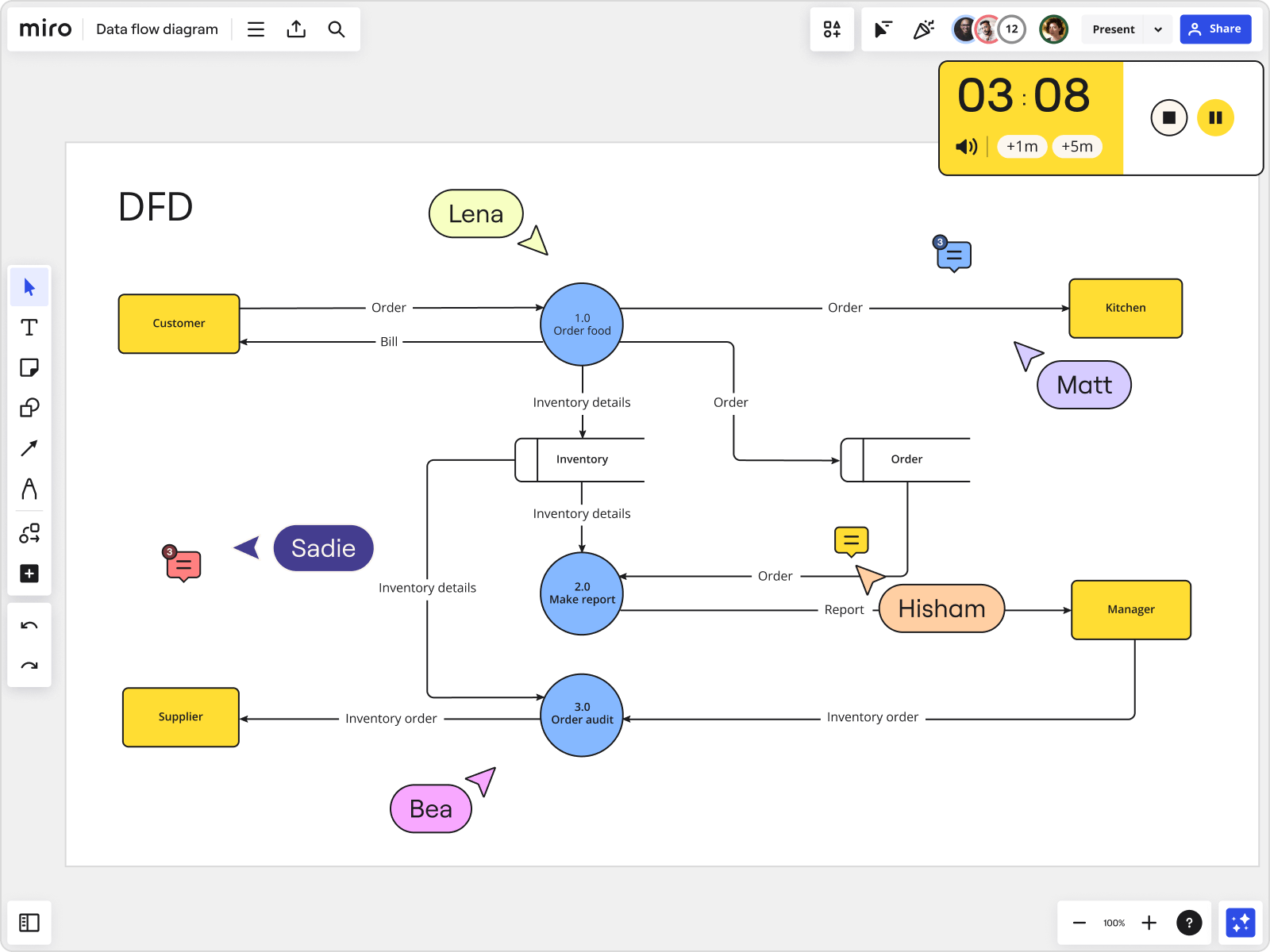

Table of Contents
Data flow diagrams: everything you need to know.
What is a data flow diagram? A data flow diagram (DFD) is a visualization that maps out the sequence of information, actors, and steps within a process or system. It uses a set of defined symbols that each represent the people and processes needed to correctly transmit data within a system.
Data flow diagrams are most often used to visually represent the flow of data within a business information system. These diagrams illustrate how data enters a system, how a system processes it, and finally, where it goes. This makes it different from a workflow diagram or flowchart , which is a broader type of visualization that can represent any other process or system within a company.
One way to identify the difference between a flowchart and a data flow diagram is to look at how the arrows are used. The arrows in a flowchart represent an order of events, while the arrows in a data flow diagram represent the flow of data and information.
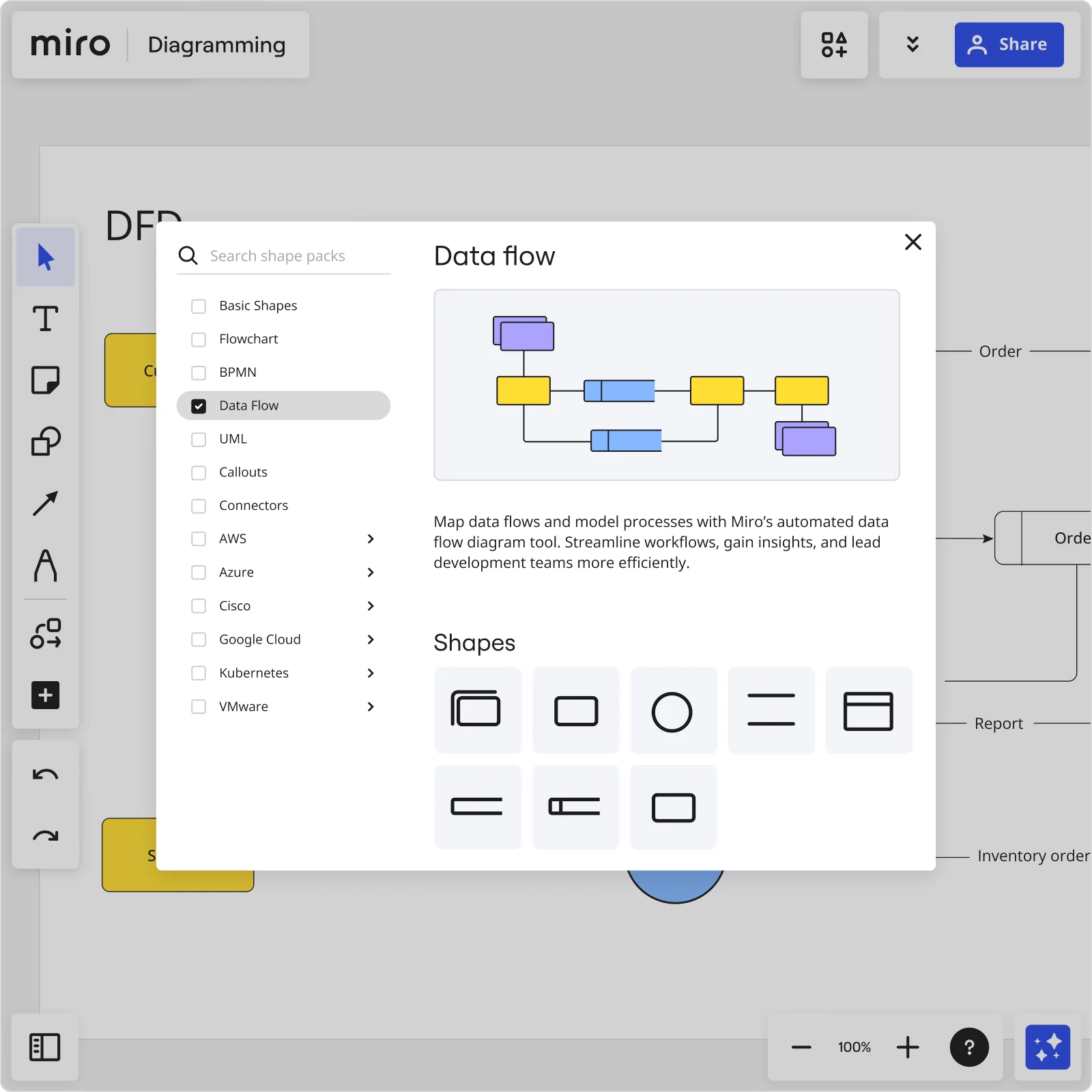
A DFD can be as simple or as complex as the system it represents, but the easiest way to make one is with a Data Flow Diagram tool .
What are the rules of a data flow diagram?
There are a few rules to keep in mind when creating a data flow diagram that’ll help you make sure your visualization is clear, consistent-looking, and accurate.
Directionality: Make sure your data flows in one direction — from the input to the output.
Connectivity: Every flow of data should lead to either a process or a data store. This makes sure that your data has a clearly defined source and destination.
Naming conventions: When labeling processes, data stores, data flows, and external entities, keep your naming consistent and clear. This helps make your data flow diagram easy to understand for teammates and stakeholders.
Process hierarchy: When representing different processes within a system, establish a clear hierarchy to differentiate broader functions from more intricate ones. This helps simplify the system’s complexity while clearly depicting a logical flow.
Symbols for data flow diagrams
There’s a set of standardized symbols used to illustrate the components of a DFD. These symbols for a data flow diagram make it easier for your team to read and understand your visualization.
External entity
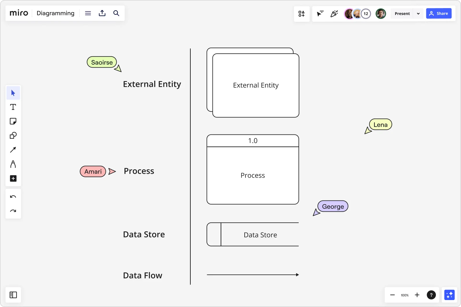
External entities are actors, sources, sinks, or terminators. They’re the components that exist outside the system, responsible for sending or receiving data. In other words, they’re the sources and destinations of the system’s inputs and outputs.
The process component represents the system’s functions, and it’s what transforms the incoming data into a usable output of data.
The data store component, as its name implies, is what stores the data in the system. Generally, these components are represented as files.
Data flow components are the pipelines through which the data is transferred in the system. In a data flow diagram, these components are generally represented as arrows and connectors.
Data flow diagram levels
Data flow diagrams are layered. Each layer of the diagram gets deeper and more intricate as it focuses on a particular piece of the system or data. The levels in a data flow diagram are usually represented from Level 0 to Level 2, and some exceptionally intricate systems may need the diagram to dive as deep as Level 3. The level of detail you want to examine will determine how deep the diagram needs to go.
Data flow diagram Level 0
Level 0 is usually the context level of a data flow diagram . It is unfocused and doesn’t generally zero in on a particular system part. Instead, at Level 0, a simple data flow diagram will provide a basic overview of the system, placing it into context and displaying a single, high-level process.
Data flow diagram Level 1
Level 1 of the diagram is where things become more detailed, and the map becomes far more focused. Level 1 highlights the main functions within the process or the system. Level 1 of a data flow diagram is where specific sections of the Level 0 overview start to get broken down and explained.
Data flow diagram Level 2
Level 2 simply goes another step deeper as it starts to map out and analyze specific sections of the Level 1 diagram. The deeper the levels go, the more text-based the diagram becomes. This is why many systems designers prefer not to go deeper than Level 2. However, for some complex and complicated systems, it may be necessary to go another level or two deeper.
How to create a data flow diagram
Now that you understand what a data flow diagram is and where these diagrams are implemented, it is time to design one for yourself. Below is a useful step-by-step guide for creating a comprehensive data flow diagram using Miro’s Data Flow Diagram Template .
1. Inputs and outputs
Start by sorting out your inputs and outputs. Each process you aim to map out should have at least one input and one output. This will ensure that your data flow diagram is complete and has no loose ends.
2. Start at Level 0
Start the diagram at Level 0 so that you can have an understanding of the system in context. This overview is useful and will let you know if you need to go into more detail in the deeper levels of the system.
3. Go into Level 1
Head into Level 1. This is where you will add meat to the bones of the structure. During the Level 1 depiction, you will want to start adding more processes and steps to your structure as you start to focus more on particular systems within the business. Remember to implement the standardized data flow diagram symbols and shapes mentioned above.
4. Add more levels as needed
Repeat the previous step and go deeper each time you want to hone in on a specific system or process. There is no cap on the number of levels you can add. But remember that you want the data flow diagram to be easily understandable. Share your diagram with your team members and invite them to leave feedback, ask questions, and make suggestions. Miro makes it easy to work with your team on a shared canvas and collaborate in real-time.
Examples of data flow diagrams
DFDs are helpful for mapping out all kinds of complex systems and processes. Let’s take a look at a few data flow diagram examples:
Online purchase system
Completing an online purchase may be as simple as clicking a ‘check out’ button and entering customer details. But there’s a lot more that goes on behind the scenes to get it done. A data flow diagram can help visualize the end-to-end process, starting from the moment a user decides to purchase something (the external input) to the moment they get their order confirmation (the external output).
In between, the DFD also visualizes how the customer data travels through the system — including where the system stores it. Not only would a DFD be helpful for understanding how online purchases occur, but also for identifying any bottlenecks or ways to improve the customer’s experience.
Customer Relationship Management (CRM) system
Managing customer data is extremely important, and many businesses turn to Customer Relationship Management (CRM) platforms to keep detailed records. A data flow diagram can provide a clear overview of how a company manages customer data. Possible inputs include a customer signing up for a free trial of a product or a customer success employee emailing a client. Possible outputs include a completed customer profile or a customer receiving a sales or product email.
A DFD not only helps businesses maintain a clear view of how they interact with customers but also to identify ways to improve relationships.
Library management system
Anyone who’s spent time in a library can imagine how much information there is to manage, from book titles to borrower statuses. Thankfully, there are databases and other management systems to keep things under control — and a data flow diagram helps visualize how they work. Potential inputs include a librarian making changes to the inventory or a user signing up for a library membership. Possible outputs include user alerts about upcoming due dates or notifications about new library members.
Creating a DFD can help identify opportunities to optimize library management and ways to improve user experience for both librarians and members.
Types of data flow diagrams
Data flow diagrams are split into two categories based on the flow that needs to be visualized. A data flow diagram can either be a logical data flow diagram or a physical data flow diagram. Each type of diagram subset has its purpose and benefits.
Logical data flow diagram
Logical data flow diagrams focus more on the activities and processes of a business. They describe the “what” and present this metric in a graphical representation. Logical data flow diagrams depict what the business does, what it provides, and what it seeks to achieve. They describe the business events and the information or data required for these events to take place. Using a logical data flow diagram is beneficial, as it maps out the flow of business actions. It helps you understand the types of functionality that your business has or may be seeking to add.
Physical data flow diagram
A physical data flow diagram graphically depicts the implementation of business systems. It represents the “how” as opposed to the “what.” It tells you how the data moves through the system and how the system works. This type of data flow diagram includes things like the files, software, and hardware of a system. Physical and logical data flow diagrams provide different perspectives of the same data flow. They can be used in conjunction to create a holistic understanding of an entire process.
When to use a data flow diagram
Data flow diagrams were originally used to show data flow in a computer system. But today, they are used in different stages of ideation and design in various industries. They are particularly beneficial to companies that rely heavily on data and information. The following are examples of where data flow diagrams are put to use:
Software engineering
Software engineers use data flow diagrams to design software foundations and architecture before getting into the coding stage of software development. These diagrams also help as an ongoing system analysis tool to measure the progress of and implement improvements to a system.
Business management
Management must fully understand the processes that make their company successful. A data flow diagram is a useful tool for designing more agile processes and generally improving a company's processes. It can be used to streamline the everyday systems and workflow of a business.
Database development
In today’s digital era, almost every business has an online component that relies on a complex database structure to house users’ information. Data flow diagrams help to map out and plot the movement and storing of data within these online databases. In a world where cyber security and data protection are key, data flow diagrams create a clear pathway for developers and businesses to follow.
Benefits of data flow diagrams
A data flow diagram graphically depicts the functions and processes within a system, which in turn helps capture, store, and manipulate the information. This visual representation is a great communicative tool that can be sent back and forth between the user and the system developer. Here are some benefits of data flow diagrams in more detail:
Sets boundaries
Implementing a data flow diagram helps describe and demarcate the boundaries of a system. Without a data flow diagram, a company might struggle to understand where a system starts and ends. By setting specific boundaries, there is a clearly defined delineation in place.
Improves communication
A data flow diagram can help foster graphical communication between system designers and users. This can help engineers and developers understand the needs and wants of the user.
Effective visualization tool
Representing a complex data structure with a simple data flow diagram makes the diagram easier to interpret. Data flow diagrams help teams visualize the data and steps involved in software-system processes. Visualization is crucial in explaining processes clearly and making them more memorable.
Represents logic
Data flow diagrams support the logic behind the data flow within a system. Without this logical underpinning and understanding, the non-technical people involved in a project might not understand how the input data becomes the output data.
Data flow diagrams and UML
We’ve looked at different types of data flow diagrams earlier. Now let’s cover how these diagrams fit into the Unified Modeling Language (UML) world. UML diagrams and data flow diagrams appear similar, but there are some key differences. UML is a modeling language used in object-oriented software development. For example, software developers use UML to offer a more detailed overview of a process and explain how software engineering is done. There are 14 official types of UML diagrams. On the other hand, data flow diagrams show how data flows through a system. They can resemble UML diagrams, but they aren’t meant to represent details of software logic. When using UML, an activity diagram can be more useful than a data flow diagram. This is because a data flow diagram is a graphical representation of how data flows through a system. In this UML Activity Diagram Template , the sequence of activities is represented similarly to the way data flows through a system.
Who uses data flow diagrams?
Anyone working on system design is likely to benefit from creating a data flow diagram . Here are a few examples of teams who might use a DFD:
Growth teams
Growth teams need to use data and understand data flows to find new growth opportunities. DFDs help them better organize and understand what influences the data, how it’s tracked, and where it’s stored.
Data analysts
Unsurprisingly, data analysts are some of the most common professionals to benefit from a DFD. Data analysts are responsible for mining data and finding insights, so the structure and system requirements of data flows are critical to their work.
Product teams
Product teams are tasked with understanding how customers interact with a product, including how their data is inputted and where it goes. As a result, they often use DFDs to trace the flow of that data as well as identify opportunities to improve the customer’s experience.
Data Flow Diagrams vs Flowcharts. What's the difference?
What is a flowchart?
Different types of diagrams: An overview of visual tools
Data flow diagram examples
Get on board in seconds
Join thousands of teams using Miro to do their best work yet.

Home » DFD » Understanding Data Flow Diagrams (DFD): A Comprehensive Guide
Understanding Data Flow Diagrams (DFD): A Comprehensive Guide
- Posted on October 10, 2023
- / Under DFD
Introduction
Data Flow Diagrams (DFDs) serve as a time-tested and traditional visual representation, offering a comprehensive insight into the intricate web of information flows within a system. This graphical tool is instrumental in illustrating how data navigates through the various facets of an information system, encompassing processes, data storage, and the generation of reports.
Hierarchy and Decomposition
One of the key strengths of DFDs lies in their ability to decompose a system into manageable subsystems. These subsystems can then be further broken down into lower-level components, creating a hierarchical structure. This hierarchical approach enables a systematic exploration of the system, with each layer dedicated to a specific process or data function. The foundational level, known as Level 0 or the context level, provides an overarching view of the entire system, while subsequent levels, such as Level 1 diagrams, delve into the specifics of individual processes.
Visualization and Documentation
Utilizing data flow diagrams facilitates a visual understanding of how data moves between different processes within a system. Information technology professionals and systems analysts leverage DFDs as a documentation tool to elucidate the intricacies of data flow to end-users. The process often begins with an overarching view, allowing analysts to gradually zoom into the finer details of each process.
Systematic Exploration
DFDs offer a systematic approach to exploring and understanding complex systems. Analysts can initiate the exploration at a higher level, capturing the essence of the entire system, before progressively zooming into the nuances of individual processes. This methodical progression ensures that the system is comprehensively documented while allowing for detailed elaboration where necessary.
Flexibility in Representation
Whether the system is manual, automated, or a combination of both, a well-constructed DFD can adapt to various scenarios. This flexibility makes DFDs a versatile tool suitable for a wide range of systems, accommodating different levels of complexity.
Preliminary Overview
DFDs are often employed as a preliminary step in system analysis. By providing an initial overview of the system without delving into excessive detail, DFDs lay the groundwork for subsequent elaboration. This strategic approach ensures that the essential components and interactions are captured efficiently before diving into the granular aspects of system requirements.
Data Flow Diagrams stand as an invaluable asset in the arsenal of information technology professionals and systems analysts. Their ability to visually represent complex data flows, facilitate systematic exploration, and adapt to various system architectures makes them a cornerstone in the process of understanding and documenting information systems. Whether used as a preliminary step or a detailed exploration tool, DFDs play a crucial role in unraveling the intricacies of modern-day systems.
Learn by Examples

Logical Data Flow Diagram Example: Grocery Store
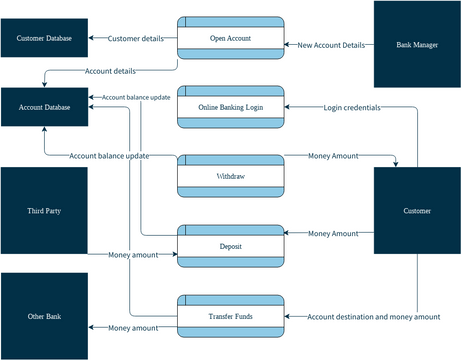
Bank Account Data Flow Diagram

Physical Data Flow Diagram Example: Grocery Store
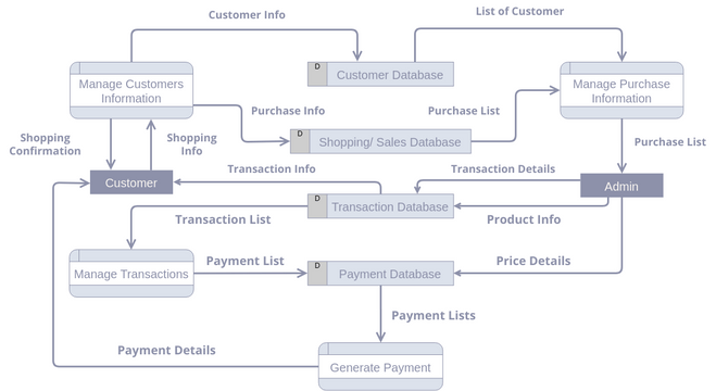
Data Flow Diagram: Purchase Management System
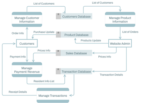
Data Flow Diagram: ECommerce System
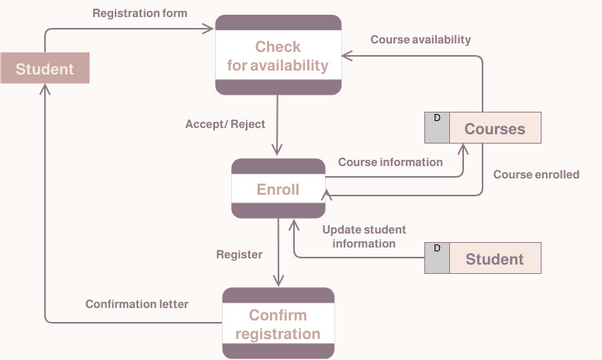
Data Flow Diagram: Student Registration System
Leave a Comment Cancel reply
Your email address will not be published. Required fields are marked *
Save my name, email, and website in this browser for the next time I comment.

- Visual Paradigm Online
- Request Help
- Customer Service
- Community Circle
- Demo Videos
- Visual Paradigm
- YouTube Channel
- Academic Partnership
Diagramming Build diagrams of all kinds from flowcharts to floor plans with intuitive tools and templates.
Whiteboarding collaborate with your team on a seamless workspace no matter where they are., data generate diagrams from data and add data to shapes to enhance your existing visuals., enterprise friendly easy to administer and license your entire organization., security see how we keep your data safe., apps & integrations connect to all the tools you use from microsoft, google workspace, atlassian, and more..
- What's New Read about new features and updates.
Product Management Roadmap features, brainstorm, and report on development, so your team can ship features that users love.
Software engineering design and maintain complex systems collaboratively., information technology visualize system architecture, document processes, and communicate internal policies., sales close bigger deals with reproducible processes that lead to successful onboarding and training..
- Getting Started Learn how to make any type of visual with SmartDraw. Familiarize yourself with the UI, choosing templates, managing documents, and more.
- Templates get inspired by browsing examples and templates available in SmartDraw.
Diagrams Learn about all the types of diagrams you can create with SmartDraw.
Whiteboard learn how to combine free-form brainstorming with diagram blueprints all while collaborating with your team., data visualizers learn how to generate visuals like org charts and class diagrams from data., development platform browse built-in data visualizers and see how you can build your own custom visualization., open api the smartdraw api allows you to skip the drawing process and generate diagrams from data automatically., shape data add data to shapes, import data, export manifests, and create data rules to change dashboards that update..
- Explore SmartDraw Check out useful features that will make your life easier.
- Blog Read articles about best practices, find tips on collaborating, learn to give better presentations and more.
Support Search through SmartDraw's knowledge base, view frequently asked questions, or contact our support team.
Site license site licenses start as low as $2,995 for your entire organization..
- Team License The SmartDraw team License puts you in control with powerful administrative features.
Apps & Integrations Connect to all the tools you use.
- Contact Sales
What's New?
Solutions By Team
Save money, reduce hassle, and get more.
Unleash your team's productivity by combining enterprise-class diagramming, whiteboarding, and data while saving 10x over Visio and Lucidchart!
Getting Started Learn to make visuals, familiarize yourself with the UI, choosing templates, managing documents, and more.
Templates get inspired by browsing examples and templates available in smartdraw., developer resources, additional resources.
Team License The SmartDraw Team License puts you in control with powerful administrative features.
Solutions for your team.
Data Flow Diagram
Easily create data flow diagrams & models in minutes, what is a data flow diagram, history of data flow diagrams, data flow diagram tutorial, data flow diagram symbols, data flow diagram levels, data flow diagram examples, with smartdraw, you can create many different types of diagrams, charts, and visuals.
A data flow diagram (DFD) illustrates how data is processed by a system in terms of inputs and outputs. As its name indicates its focus is on the flow of information, where data comes from, where it goes and how it gets stored.
Watch this short video about data flow diagrams:
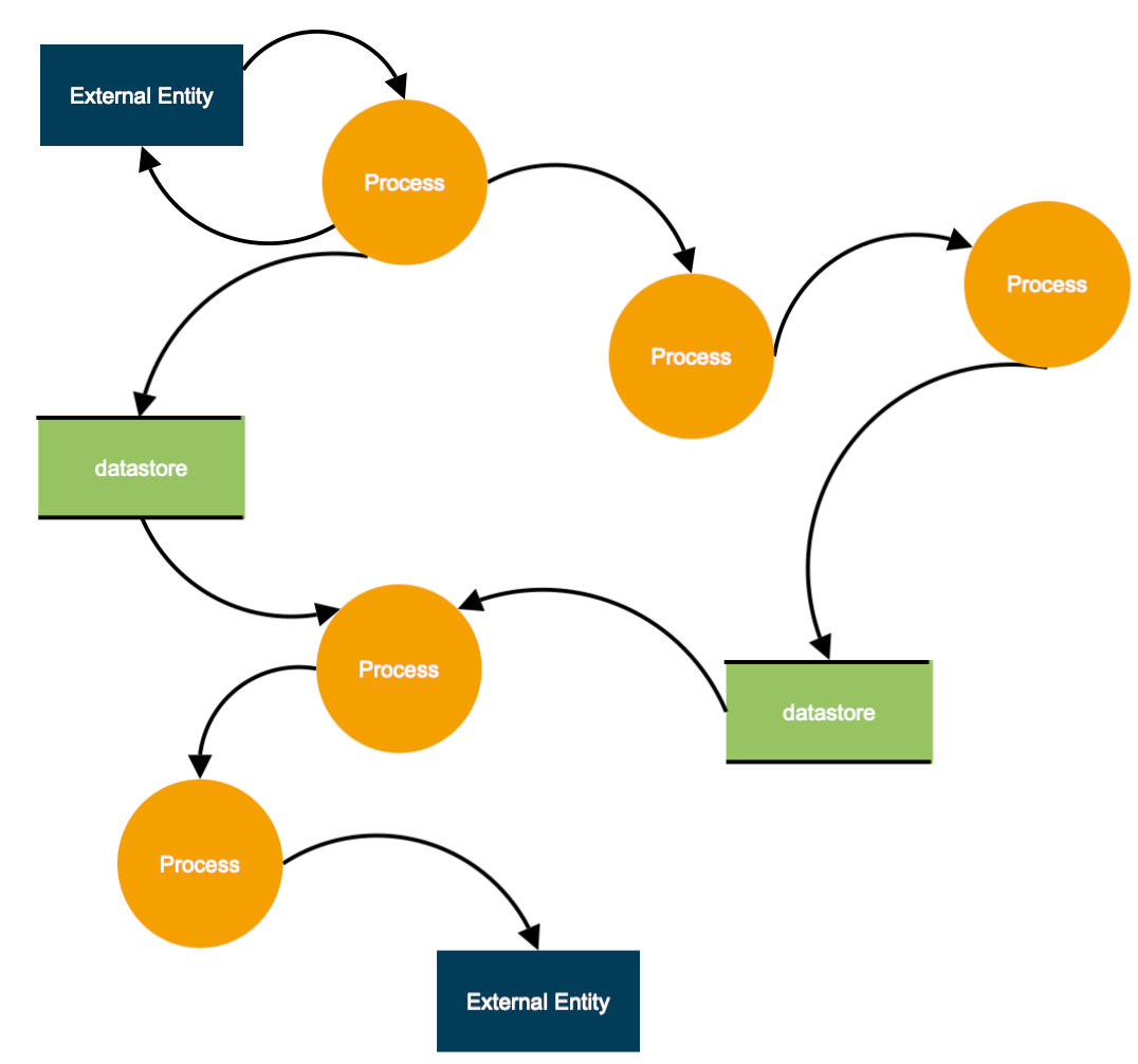
Data flow diagrams became popular in the 1970s in software development. They were first described in a classic text about Structured Design written by Larry Constantine and Ed Yourdon. Yourdon & Coad's Object Oriented Analysis and Design (OOA/OOD) was a way of visualizing software systems before UML diagrams .
SmartDraw contains all the needed data flow diagram symbols and easy-to-use templates that help you get started. Stamp shapes to your drawing area and connect them easily with keyboard shortcuts or intuitive commands located on the SmartPanel to the left of your drawing area.
You can even nest different levels of data flow diagrams by using SmartDraw's hyperlink function.
Learn more by reading this tutorial on making data flow diagrams .
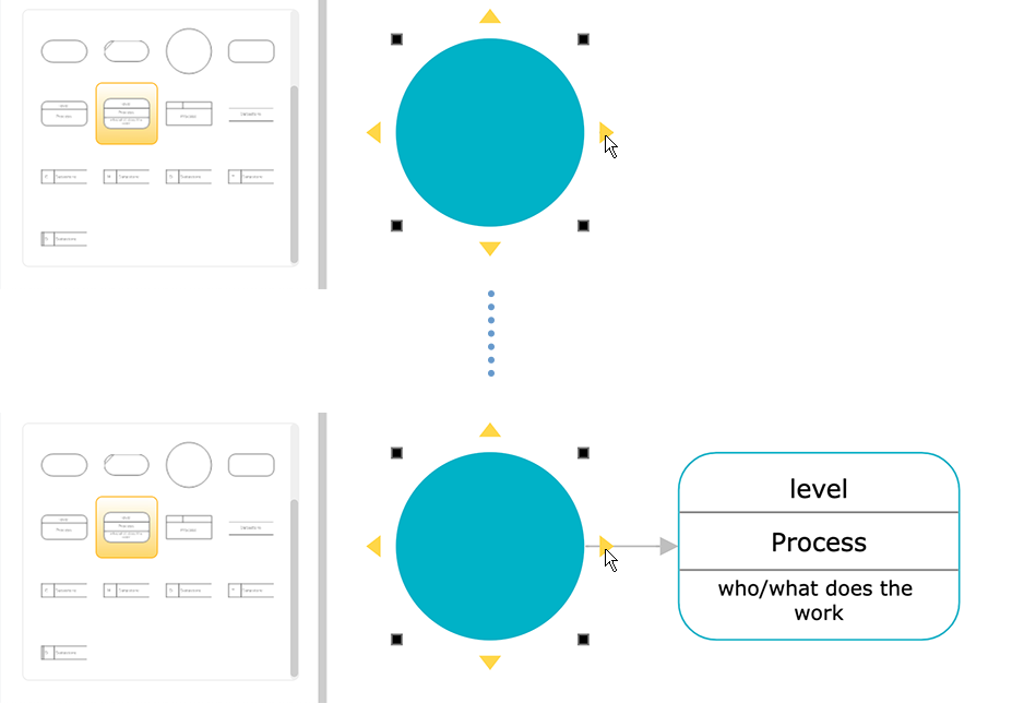
Data Flow Diagrams Symbols
There are essentially two different types of notations for data flow diagrams (Yourdon & Coad or Gane & Sarson) defining different visual representations for processes, data stores, data flow and external entities.
Yourdon and Coad type data flow diagrams are usually used for system analysis and design, while Gane and Sarson type DFDs are more common for visualizing information systems.
Visually, the biggest difference between the two ways of drawing data flow diagrams is how processes look. In the Yourdon and Coad way, processes are depicted as circles, while in the Gane and Sarson diagram the processes are squares with rounded corners.
Process Notations. A process transforms incoming data flow into outgoing data flow.
Datastore Notations. Datastores are repositories of data in the system. They are sometimes also referred to as files.
Dataflow Notations. Dataflows are pipelines through which packets of information flow. Label the arrows with the name of the data that moves through it.
External Entity Notations. External entities are objects outside the system, with which the system communicates. External entities are sources and destinations of the system's inputs and outputs.
Context Diagram. A context diagram is a top level (also known as "Level 0") data flow diagram. It only contains one process node ("Process 0") that generalizes the function of the entire system in relationship to external entities.
DFD Layers. Draw data flow diagrams can be made in several nested layers. A single process node on a high level diagram can be expanded to show a more detailed data flow diagram. Draw the context diagram first, followed by various layers of data flow diagrams.
DFD Levels. The first level DFD shows the main processes within the system. Each of these processes can be broken into further processes until you reach pseudo code.
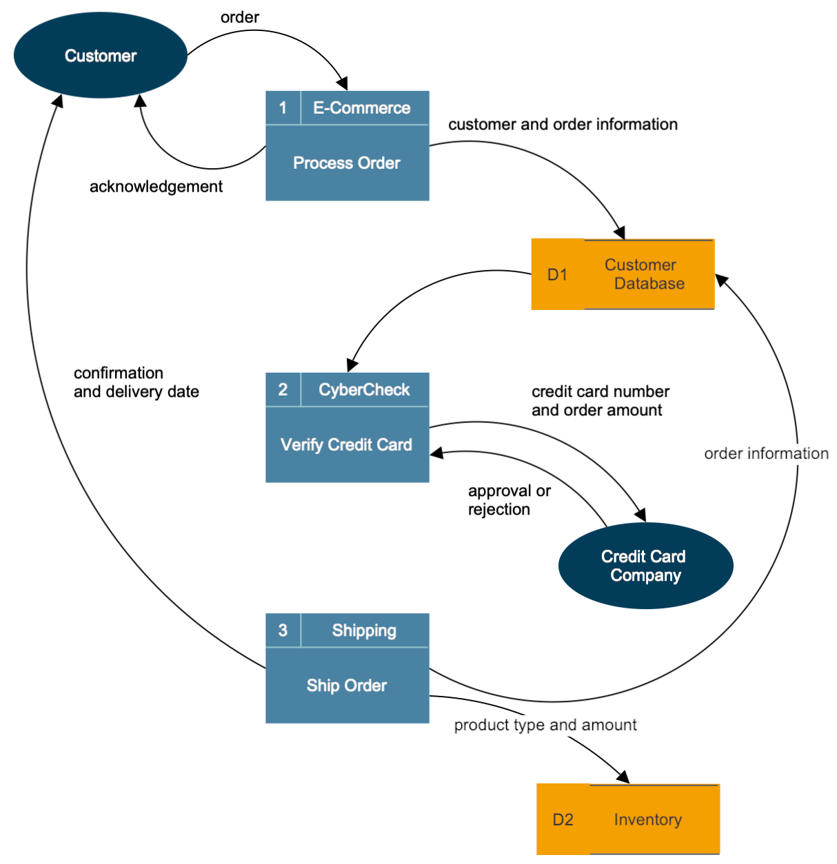
Click on any of these data flow diagrams included in SmartDraw and edit them:
Browse SmartDraw's entire collection of data flow diagram examples and templates
More Data Flow Diagram Information
- Data flow diagram software
- Software design diagram templates
- UML diagram tool
- Game design software
- Visio ® for Mac
Try SmartDraw's Data Flow Diagram Software Free
Discover why SmartDraw is the best data flow diagram software today.
Data Flow Diagram: A Comprehensive Guide
This guide is brought to you by Zen Flowchart, the simplest flowchart maker .
A data flow diagram (DFD) is type of flowchart , a graphical representation of the flow of data through an information system. It is also known as a data flow diagram, function diagram, or process diagram. Data flow diagrams are used to design the architecture of an information system and to document the functional aspects of it.
Data Flow Diagram
A data flow diagram (or DFD) is a graphical representation of the information flow in a business process. It demonstrates how data is transferred from the input to the file storage and reports generation.
By visualizing the system flow, the flow charts will give users helpful insights into the process and open up ways to define and improve their business.

DFD was highlighted in the book “ Structured Design ” by Ed Yourdon and Larry Constantine in the 1970s. With the success of the structures design concept in the software engineering field, people began to acknowledge DFD as a useful tool. From there, its scope of usage expanded, especially in business circles.
There are other people who contributed to developing this method, such as Tom DeMarco , Chris Gane, and Trish Sarson. They came up with the symbols and notations used in process flow diagrams.
Components
External entity.
An external entity, also known as terminators, sources, sinks, or actors, is an outside process where information enters or leaves the system. It acts as the source and the destination of the information.
Thus, it is usually placed at the edge of the diagram. External entities can either be a person, an organization, or a computer system.
Unlike other flowchart symbols, which are triangles, rectangles, or circles, a DFD uses stick-figure drawings to demonstrate external entities.
The process is a procedure that makes changes to the information and its flow, resulting in new output. A process can perform several functions, from carrying out computations, categorizing information based on logic, or using business rules to change the flow.
It is labeled with a short and simple term that describes the whole process, such as “Submit payment”.
Data store is a place that contains information for later use. It can be files, documents, or a filing cabinet. A data store stays between two processes, receiving and sending the inputs and outputs. In business process diagrams, this component is in the form of two horizontal lines.
Data flow is the direction that the information takes to pass from external entities to processes and stores. A DFD shows this route by using arrows and succinct labels. Users will get the interface among the three components above by observing the system’s information path.
Levels In A DFD
A DFD can be divided into levels and layers, starting with level 0; thus, users can focus on describing a particular stage.
This level, known as the Context Level, zeroes in on the whole system and its connection to the external entities. Users can digest the system as a high-level process with a broad overview when using a level 0 DFD. It is designed to be straightforward so that a wide range of audiences can easily digest it.
Level 1 DFD is a more detailed level than the first one. It still describes the whole system but with emphasis on its main function and more sub-processes for easy digestion.

The next level goes deeper into parts of the previous one by dividing them into smaller sub-processes, requiring more text to narrate the details thoroughly.
Level 3 And Beyond
Level 3 and beyond are possible to make. However, diving in too deep into the small details can complicate the tool, hindering communications and efficiency.
Advantages Of A DFD
Data flow diagrams (DFDs) are a type of diagramming technique used in systems analysis and data modeling to represent system tasks and how they interact with each other. This can be seen as a notation for process flow charts. It provides instructions on how to process data. Data flow diagrams can help identify where problems in the system may be, allowing for the system to be repaired or redesigned before it falls apart. DFDs are also useful for teaching about the basics of computer science because it demonstrates how computers work by way of manipulating information, which is basically what all computers do.
Data flow diagrams provide a way for people who are involved in the process (such as managers and engineers) to better understand how objects are used in the system. It enables them to see how data is transferred from one object to the next, making it easier to spot errors. Data Flow Diagrams also offer a more natural and intuitive way for people unfamiliar with computers or programming languages to understand what's happening in the system.
When Can You Use A DFD?
A data flow diagram is a useful and flexible tool that can be helpful in different contexts.
In Business
In business, DFDs can be used to analyze since it breaks down the system and exposes flaws and bottlenecks. Plus, the tool’s graphic and simple representation gives the audience a deeper level of understanding.

Aside from business analysis, this method is also beneficial in re-engineering processes. This is a result of the former appliance. When users learn from the discovered inefficiencies, they can build a better data flow for their business.
In Software Engineering
Before developers get to the coding step, they have to carry out research on technical development. A data flow diagram is a great tool to do pre-code planning.
In System Structures
As mentioned above, DFDs reveal ways to improve a plan by uncovering its flaws. That is useful not only in business but also in many other fields. Whether technical or non-technical, you can use this tool to analyze and perfect your system structures.
How To Make A Data Flow Diagram?
Rules to make a dfd.
Before getting to the steps, let’s go through some rules on making one first.
- Each process needs to have a minimum of one input and one output.
- Since the data store receives and sends information, there should be data going in and out of it.
- The system’s information has to transform to produce output, so it needs to go through a process.
- Any process in this diagram must go to another process or a data store.

Detailed Steps
Choose the process.
Since different processes use DFD on different levels, selecting the process is important. Although a whole system can be put in a DFD, remember that larger processes come with difficulties to contextualize them. Hence, you should find out the piece you want to perfect and focus on it.
Sort Out The Business Activities
All of the activities in the process need to be categorized into four components: external entity, process, data flow, and data store.
Draw The Diagram
After the information is neatly grouped, you can start drawing your DFD. There are two ways to do this: by hand or using a diagram template and software .
Checking is always necessary to ensure your work is qualified. You should look for missed steps, redundant details, or unnecessary complexity in this step.
Creating Child Diagrams And Expanding
Once you have done the first diagram (the level 0 one), you can start working on the child diagram. Later, they will act as connectors between processes.
If you want to go deeper into analyzing the process, use level 1 and beyond diagrams to achieve the desired thoroughness.
Related Guides
Flowchart guides, brought to you by, zen flowchart.
A Beginner's Guide to Data Flow Diagrams
Published: September 06, 2023
Ask any professional athlete or business executive how they became successful, and they’ll tell you they mastered a process. By figuring out which habits led to success and which didn’t, they improved their efficiency and productivity.

But implementing a process into a business, department, or even a team is a completely different animal than honing your personal process. With so many moving parts, how do you track and refine each aspect of your business process?
![data flow diagram representation Download Now: An Introduction to Data Visualization for Marketers [Free Guide]](https://no-cache.hubspot.com/cta/default/53/6ecf26a9-faff-4c16-a2d4-b70751ce8b65.png)
Data flow diagrams provide a straightforward, efficient way for organizations to understand, perfect, and implement new processes or systems. They’re visual representations of your system, making it easy to understand and prune.
Before we dive into how data flow diagrams can help refine any of your business systems or processes, let’s go over what exactly it is.
What is a data flow diagram (DFD)?
A data flow diagram (DFD) is a visual representation of the information flow through a process or system. DFDs help you better understand process or system operations to discover potential problems, improve efficiency, and develop better processes. They range from simple overviews to complex, granular displays of a process or system.
An Introduction to Data Visualization
Learn how to design compelling charts & graphs that are easy to understand, including:
- Tools and Software for Data Visualization
- Data Types, Relationships, and Formats
- How to Effectively Visualize Data
- A History of Data Visualization
Download Free
All fields are required.
You're all set!
Click this link to access this resource at any time.
The Benefits of Data Flow Diagrams
DFDs are visual representations that can help almost anyone grasp a system‘s or process’ logic and functions. Aside from being accessible, they provide much-needed clarity and improve productivity. Here's how.
Accessibility
Because visual information is easier to digest, DFDs typically explain complex concepts better than blocks of text can.
Visual presentations of how a process works can also hold people's attention longer — making it easier to retain the information.
DFDs clarify the systems and processes necessary for your team to do their best work. Whether implementing a new company-wide system or refining a department's existing process, a DFD gets you and your team on the same page.
Creating DFDs will give you clarity about business operations, too. A clearer understanding enables you to refine and track your business processes with less friction.
Productivity
The accessibility and clarity created with DFDs will leave less room for error. Your team will better master systems and processes because they understand them.
Greater understanding — paired with a repeatable process — will likely boost team effectiveness and productivity.
On a broader level, DFDs can help you streamline your business operations. When mapping out your processes, you‘ll gain insights into what does and doesn’t work.
These insights help boost you and your team's productivity. As a bonus, you can share any best practices across departments.
Data Flow Diagram Symbols
Before using a DFD, you need to know the symbols used to describe it.
Data flow diagram symbols are standardized notations, like rectangles, circles, arrows, and short-text labels. These symbols represent a system’s data flow direction, inputs, outputs, storage points, and sub-processes.
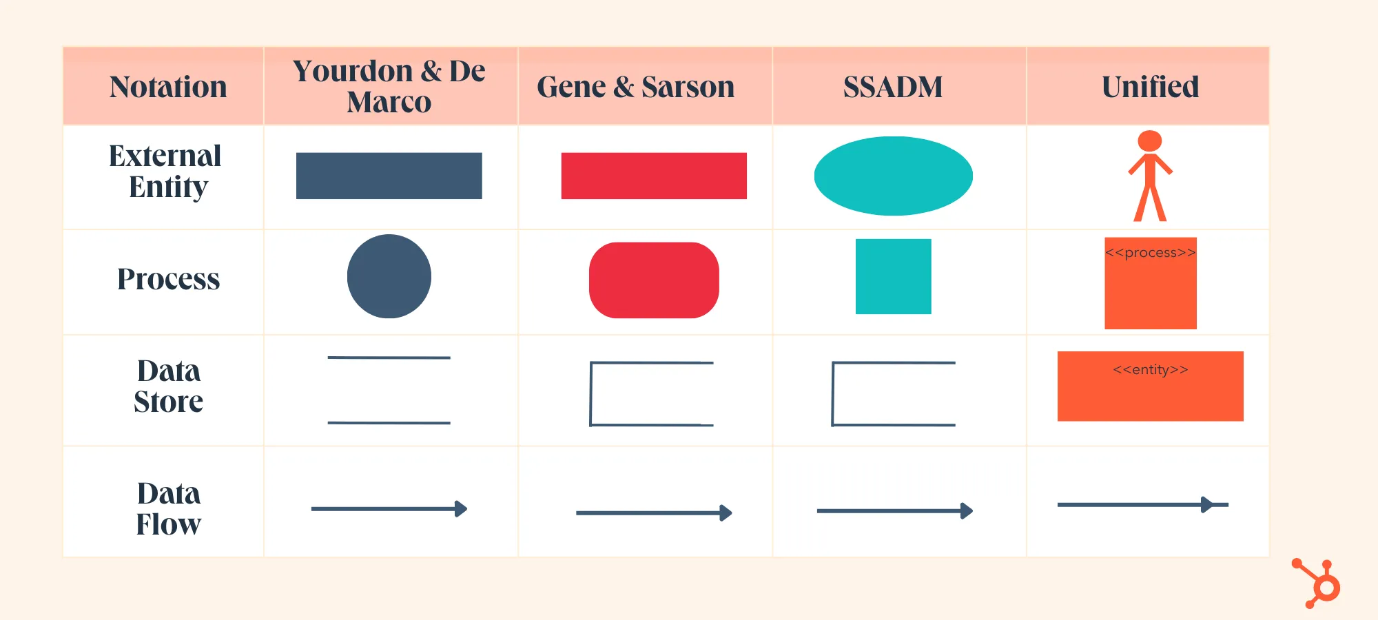
Four common methods of notation are used in DFDs: Yourdon & De Marco, Gene & Sarson, SSADM, and Unified.
All use the same labels and similar shapes to represent the four main elements of a DFD — external entity, process, data store, and data flow.
Don't forget to share this post!
Related articles.

Permalinks: What They Are & How to Structure Them for Max SEO Value

What is Website Architecture? 8 Easy Ways to Improve Your Site Structuring

Image Alt Text: What It Is, How to Write It, and Why It Matters to SEO
Diving Deep Into Technical SEO for Ecommerce (My Takeaways)

How Your JavaScript Can Benefit Your SEO

Everything You Need to Know About Google Search Essentials (formerly Google Webmaster Guidelines)

Duplicate Content Issues on Your Website? Easy Ways to Find and Fix Them

The Ultimate Guide to Google Search Console in 2024

Does Google Think Your Website Is Spam?

The Top 11 Search Engines, Ranked by Popularity
How to design compelling charts & graphs that are easy to understand
Marketing software that helps you drive revenue, save time and resources, and measure and optimize your investments — all on one easy-to-use platform
What Are Data Flow Diagrams?
Last updated: May 16, 2023
- Software Architecture
1. Introduction
A data flow diagram (DFD) is a graphical representation of data flow through a system. It’s employed to understand how data is processed, stored, and communicated within a system. Moreover, DFD is used to support the analysis of how the data flows in existing or proposed systems from one page or module to another (using a flowchart ). It’s also called a bubble chart.
In this tutorial, we’ll learn the basics of DFD, its purpose, components, levels, and how to create a DFD.
2. Data Flow Diagrams
DFDs represent the flow of data in a system or process. They help identify the flow of data and potential bottlenecks in the system. They also help to communicate the structure of a system to non-technical stakeholders and provide a visual representation of the system’s architecture .
2.1. Components of a Data Flow Diagram
A DFD consists of four main components:
- External Entity : this is also called source, sink, or terminator. External entities are the sources or destinations of data entering or leaving the system. They can be users, systems, or organizations that provide or retrieve data from the system. An external entity is represented by a rectangle in the DFD.
- Data Flow : data flows indicate the data movement between external entities, processes, and the data store. They’re represented as arrows in the DFD with a short text label.
- Process : processes mean data transformation from one form to another. Processes are represented as circles in the DFD.
- Data Store : data stores indicate a location where data is stored and managed. Data is stored and retrieved by different processes in the DFD. Data stores are represented by rectangles with one or both of its smaller sides missing or simply two horizontal lines in the DFD.
2.2. Levels of DFDs
DFDs can present from simple overviews to complex, granular representations of a system or process, starting with level 0. The following is a breakdown of the different levels of DFDs:
- Context Diagram (Level 0) : a general overview of a system is usually represented with a high-level DFD called a context diagram or Level 0 DFD. These diagrams are designed to be simple and straightforward overviews of a process or system, making them easily comprehensible to a broad audience. It only contains one process node (“Process 0”) that generalizes the entire system’s functionality.
- Decomposition (Level 1) : DFDs at Level 1 are still broad overviews of a system or process but are more detailed than Level 0 diagrams. A level 1 diagram provides additional detail and highlights the primary functions of a system. They break down the system’s single process node into subprocesses, providing more insight into the underlying processes.
- Deeper Dives (Level 2) : the next level of DFDs provides even more detailed information by breaking down each Level 1 process into granular subprocesses. This level provides a deeper understanding of the system or process. It helps identify inefficiencies and areas for improvement.
- Increasing Complexity (Level 3) : DFDs with Levels 3 and higher are uncommon because they require enormous detail, which can defeat the purpose of creating a DFD. However, these diagrams can be helpful in complex systems or processes that require a detailed understanding of how data flows through the system.
3. Creating a Data Flow Diagram
DFDs can be created using specialized software such as Visio, online tools such as Draw.io or Lucidchart, or manual drawing. The process of creating a DFD involves several steps:
- Identify the external entities : Identify the sources and destinations of data in the system.
- Determine the flow of data : Identify the data flow between the entities and create a data flow diagram.
- Define the processes : Identify the data transformations and create a process for each transformation. Each process should have at least one input and output.
- Add data stores : Identify the locations where data is stored and add data stores to the DFD. Each data store should have at least one data flow input and one output. A data store cannot be associated with external entities directly. Instead, it must go through at least one process.

3.1. Example
Let’s consider an example of a simple account management system. This system has an external entity: the user interacting with it. The user can either log in or register. The account management system validates user information and updates the records.
A simple context and level 1 diagram for the account management system would look like the following image:
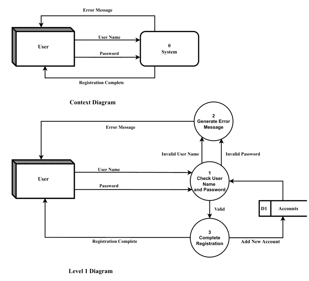
In this example, the external entities are represented as rectangles. The data flows are represented as arrows, and the processes are represented as circles. The data store is represented as a rectangle with one smaller side open. The context diagram gives a high-level overview of the system.
A user provides his/her user name to the system, and the system either returns an error or a message for successful registration. The level diagram breaks down the context diagram and includes three processes that check the user name and password, create an error message, or complete the registration. Process 1 retrieves data from the data store “D1-Accounts”, and process 2 adds the data in the form of user name and password.
4. Conclusion
In this article, we explored the DFD as a tool for understanding data flow within a system . They help to identify potential bottlenecks and communicate the structure of a system to stakeholders. Heterogeneous elements are employed to graphically represent the flow of data and its processing within the system.
DFDs can vary in complexity, starting with level 0 as the most basic and progressing to higher levels with more detailed information. While the higher-level DFDs can be helpful, they may only sometimes be necessary, and it’s essential to balance the level of detail with the overall purpose of the diagram.
By understanding the components of a DFD and the steps involved in creating it, we can deeply study the architecture of any system.

- Demo Videos
- Interactive Product Tours
- Request Demo
What is Data Flow Diagram (DFD)? How to Draw DFD?
Compatible edition(s): Enterprise , Professional , Standard , Modeler
- January 27, 2012
- Views: 2,215,366
What is a data flow diagram (DFD)?
A picture is worth a thousand words. A Data Flow Diagram (DFD) is a traditional way to visualize the information flows within a system. A neat and clear DFD can depict a good amount of the system requirements graphically. It can be manual, automated, or a combination of both.
It shows how information enters and leaves the system, what changes the information and where information is stored. The purpose of a DFD is to show the scope and boundaries of a system as a whole. It may be used as a communications tool between a systems analyst and any person who plays a part in the system that acts as the starting point for redesigning a system.
It is usually beginning with a context diagram as level 0 of the DFD diagram, a simple representation of the whole system. To elaborate further from that, we drill down to a level 1 diagram with lower-level functions decomposed from the major functions of the system. This could continue to evolve to become a level 2 diagram when further analysis is required. Progression to levels 3, 4 and so on is possible but anything beyond level 3 is not very common. Please bear in mind that the level of detail for decomposing a particular function depending on the complexity that function.
DFD Diagram Notations
Now we'd like to briefly introduce to you a few diagram notations which you'll see in the tutorial below.
External Entity
An external entity can represent a human, system or subsystem. It is where certain data comes from or goes to. It is external to the system we study, in terms of the business process. For this reason, people used to draw external entities on the edge of a diagram.
.png)
What will we do in this tutorial?
In this tutorial, we will show you how to draw a context diagram, along with a level 1 diagram.
Note: The software we are using here is Visual Paradigm . You are welcome to download a free 30-day evaluation copy of Visual Paradigm to walk through the example below. No registration, email address or obligation is required.
How to Draw Context Level DFD?
- To create new DFD, select Diagram > New from the toolbar.
- In the New Diagram window, select Data Flow Diagram and click Next .
- Enter Context as diagram name and click OK to confirm.
How to Draw Level 1 DFD?
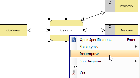
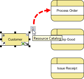
- The data stores and/or external entities connected to the selected process ( System ) would be referred to in the level 1 DFD. So when you are prompted to add them to the new diagram, click Yes to confirm. Note: The new DFD should look very similar to the Context diagram initially. Every element should remain unchanged, except that the System process (from which this new DFD decomposes) is now gone and replaced by a blank space (to be elaborated).
- Rename the new DFD. Right-click on its background and select Rename... . In the diagram's name box, enter Level 1 DFD and press ENTER .
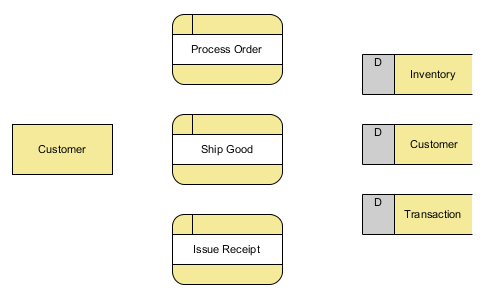
Wiring with connection lines for data flows
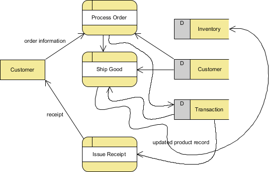
The remaining steps in this section are about connecting the model elements in the diagram. For example, Customer provides order information when placing an order for processing.
How to Improve a DFD's Readability?
The completed diagram above looks a bit rigid and busy. In this section, we are going to make some changes to the connectors to increase readability.
More DFD Examples
The list below directs you to various Data Flow Diagram examples that cover different businesses and problem domains. Some of them consist of the use of multiple context levels.
- Customer Service System
- Food Ordering System
- Securities Trading
- Supermarket App
- Vehicle Maintenace Depot
- Video Rental Store
- Order-Processing.vpp
- Order-Processing_result.vpp
Readers of this tutorial also read
- Data Flow Diagram: Examples - Food Ordering System
- How to Write Effective Use Cases?
- How to Develop As-Is and To-Be Business Process?
- How to Model Relational Database Design with ERD?
- Data Flow Diagram with Examples - Customer Service System
- Enterprise Architecture
- TOGAF ADM Software: How to Use?
- Drawing ArchiMate Diagram
- Design & Modeling
- Problem Desc. to Model
- Creating Activity Diagram
- Creating State Machine Diagram
- Creating Component Diagram
- Creating Deployment Diagram
- Cause and Effect Diagram
- Drawing Timing Diagram
- Class Diagram in Java, C# and VB
- Animating Activity Diagram
- Drawing Profile Diagram
- Attach file reference to model
- Using sub-diagrams
- UML Package Diagram
- Mult-party service in SoaML
- Drawing SoaML Diagram
- Stereotypes and tagged values
- Define custom element properties
- Merge actors in use case diagram
- Numbering sequence messages
- Using Textual Analysis
- Seq. Diagram duration constraint
- Fill-in UML state's body
- Edit attribute's initial value
- Drawing Sequence Diagram
- Test cases for SysML requirement
- Customize requirement types
- Drawing Communication Diagram
- Develop Sequence Diagram with keybaord
- Abstract Factory Pattern Tutorial
- Factory Method Pattern Tutorial
- Builder Pattern Tutorial
- Prototype Pattern Tutorial
- Singleton Pattern Tutorial
- Adapter Pattern Tutorial
- Proxy Pattern Tutorial
- Composite Pattern Tutorial
- Bridge Pattern Tutorial
- Decorator Pattern Tutorial
- Flyweight Pattern Tutorial
- Facade Pattern Tutorial
- Command Pattern Tutorial
- Chain of Responsibility Pattern Tutorial
- Interpreter Pattern Tutorial
- Iterator Pattern Tutorial
- Observer Pattern Tutorial
- Memento Pattern Tutorial
- Mediator Pattern Tutorial
- Template Pattern Tutorial
- Strategy Pattern Tutorial
- State Pattern Tutorial
- Visitor Pattern Tutorial
- Create BPMN diagram
- Business process modeling
- Business Process Mapping
- Creating BPMN diagram
- Using Data Object in BPMN
- BPD Example - Leave Application
- BPMN Intro I
- BPMN Intro II - Swimlanes
- BPMN Intro III - Flow/Connectors
- BPMN Intro IV - Data & Artifacts
- Develop As-is & To-be BPD
- Working procedures of BP tasks
- Link data object with ERD entity
- Animate BPMN business process
- BPMN process simulation
- Import Bizagi project
- Use stereotype in EPC Diagram
- Secondary pools for BPMN task
- Drill-down a BPMN sub-process
- Process simulation example
- Drawing BPMN Conversation Diagram
- BPMN 2.0 BPD
- Create Circuit Diagram
- Create Venn Diagram
- Create Floor Plan
- Create Network Diagram
- Flowchart Tutorial
- DFD Example - Customer Service
- DFD Example - Food Ordering
- DFD Example - Securities Trading
- DFD Example - Supermarket App
- DFD Example - Vehicle Main. Depot
- DFD Example - Video rental
- Functional decomposition in DFD
- Data Flow Diagram Tutorial
- Using Storyboard with User Story
- Wireframe for Android apps design
- Product Breakdown Structure
- Work Breakdown Structure
- Radar Chart tutorial
- Creating Fishbone Diagram
- Customer Journey Mapping (CJM)
- Create stereotyped model element
- Bookmark shapes
- Select shapes with Handi-Selection
- Diagram annotation with layer
- Diagram Info Shape
- Appearance of stereotyped shape
- Tidy-up diagram with Sweeper/Magnet
- Convert model element's type
- Import Visio drawing as stencil
- Create Mind Map
- What is Mind Mapping? How to Draw a Mind Map?
- Edit model elements with Excel
- Associat parent & subdiagram flow
- Listing elements with grid
- Ad-hoc idea capturing with Brainstorm Diagram
- Identify use cases from BP process
- Refactor classes to ref. project
- Create project reference
- Create nickname for multi-name set
- Animating Sequence Diagram
- Organize domaing and impl. model
- Align business goal & logic with Decision Table
- Decision Table in-action
- Discover business logic with Decision Table
- Sensible business with Decision Table
- Decision Table in EA
- Using Matrix Diagram
- Using Analysis Diagram
- SWOT Analysis Tutorial
- Five Forces Analysis Tutorial
- Agile Requirements
- Add classes to flow-of-events
- Advanced use case flow-of-events
- Test procedures in flow-of-events
- Produce use cases from BPD
- Agile Scrum Tutorial
- User Story - Confirmation items
- Mapping BPMN with User Stories
- Using Storyboard
- Using tag on user story
- Model business goals of a system
- Using UeXceler - YouTube example
- Writing effective use case
- Generate Seq. Diagram from user story
- Generate Activity Diagram from user story
- Code & DB
- Generate ERD from RedShift DB
- Generate RedShift DB from ERD
- Compare logical and physical ERD
- Design & generate SQL Server DB
- Generate ERD from DDL
- Generate DB spec. from DB
- Keep data dict. in-sync with ERD
- Database design with ERD
- Edit nullable column in ERD
- Insert sample data into ERD
- Model RDBMS with ERD
- Generate class diagram from ERD
- Oracle DB design tool
- Oracle DB design with ERD
- Mass edit DB design with Excel
- Oracle DB reverse engineering
- Generate DB change script
- Compare DB schemas visually
- Define custom implementations for ORM Class
- Hibernate ORM in Eclipse
- Using Hibernate Criteria
- Generate Hibernate mapping for Oracle DB
- Java round-trip engineering
- C++ round-trip engineering
- Generate code from State Machine
- REST API - Twitter example
- REST API - Simple Reg. example
- Form Seq. Diagram from Java
- Hibernate ORM in NetBeans
- Visual modeling in NetBeans
- UML modeling in Eclipse
- C# round-trip engineering
- Generate C# from UML in VS
- Generate Java from UML classes in NetBeans
- Keep code and UML model in-sync in Eclipse
- Task Management Guide
- Share & review process design
- Share & discuss BPD online
- Prioritize tasks in Tasifier
- Storing reference files in project
- View and Revert changes with Visual History
- Communicate process design with PostMania
- Communicate software design with PostMania
- Concurrent process modeling
- Create Use Case report
- Create software req. spec.
- Customize Doc. Composer templates
- Maintain project of glossary
- Maintain glossary for terms
- Build glossary from class model
- Extract glossary from BPMN process
- Extract glossary terms from shapes' name
- Track occurrence of glossary terms
- Derive use case from terms
- Derive data dict. from Textual Analysis
- Generate RACI from BPMN
- Customize RACI chart
- Develop Visual Paradigm plug-in
- Change application's font settings
- Hide-away toolbar buttons

I am extremely pleased in both its ease of use as well as its breadth of features. Of particular value to me is the Textual Analysis tool.
Prof. William Burrows
University of Washington, Seattle
Turn every software project into a successful one.
We use cookies to offer you a better experience. By visiting our website, you agree to the use of cookies as described in our Cookie Policy .
© 2024 by Visual Paradigm. All rights reserved.
- Privacy statement
We use essential cookies to make Venngage work. By clicking “Accept All Cookies”, you agree to the storing of cookies on your device to enhance site navigation, analyze site usage, and assist in our marketing efforts.
Manage Cookies
Cookies and similar technologies collect certain information about how you’re using our website. Some of them are essential, and without them you wouldn’t be able to use Venngage. But others are optional, and you get to choose whether we use them or not.
Strictly Necessary Cookies
These cookies are always on, as they’re essential for making Venngage work, and making it safe. Without these cookies, services you’ve asked for can’t be provided.
Show cookie providers
- Google Login
Functionality Cookies
These cookies help us provide enhanced functionality and personalisation, and remember your settings. They may be set by us or by third party providers.
Performance Cookies
These cookies help us analyze how many people are using Venngage, where they come from and how they're using it. If you opt out of these cookies, we can’t get feedback to make Venngage better for you and all our users.
- Google Analytics
Targeting Cookies
These cookies are set by our advertising partners to track your activity and show you relevant Venngage ads on other sites as you browse the internet.
- Google Tag Manager
- Infographics
- Daily Infographics
- Popular Templates
- Accessibility
- Graphic Design
- Graphs and Charts
- Data Visualization
- Human Resources
- Beginner Guides
Blog Graphs and Charts Data Flow Diagram: What Is It, Examples & How to Create One
Data Flow Diagram: What Is It, Examples & How to Create One
Written by: Cristian Oana Apr 01, 2022
So many moving parts go into an organization’s day-to-day systems and operations. Without the proper tools and techniques, it can be difficult to keep track of all the important details. This is where a data flow diagram or DFD comes in.
I’ve put together a crash course to help you master this powerful management tool. From the different kinds of diagrams to their layouts, symbols and functions—this short guide will take you through it all so you can quickly make your own in no time.
You can create your own DFDs with Venngage’s diagram maker , even without diagramming experience. Our customizable data flow diagram templates are made by experts for non-designers.
Click to jump ahead:
What is a data flow diagram (DFD)?
What are the components of a data flow diagram (dfd), 3 data flow diagram (dfd) examples, how to create data flow diagrams, what are the types of data flow diagrams (dfd), what are the uses of data flow diagrams (dfd), why is a data flow diagram essential in business processes, faqs on data flow diagrams.
A data flow diagram is a visualization tool used to illustrate the flow of processes in a company or a specific project within it. It highlights the movement of information as well as the sequence of steps or events required to complete a work task.
DFDs can vary in design and complexity, depending on the process it represents. It can be a simple outline of a general system or a more granular sketch of a multi-level procedure, such as the example below.

By visually dissecting these otherwise abstract concepts, DFDs allow teams and managers to better comprehend how a system works as well as identify and troubleshoot potential problems to improve effectiveness.
A data flow diagram is typically organized hierarchically, showing the entire system at one level, followed by major subsystems at the next. Finally, details are shown for each primary subsystem, with components identified last.
Here’s an example, which details the flow of customer data through the different layers of a business transaction.

Each of the diagram’s elements is assigned a specific shape or symbol to stress its role in the process. More on those symbols later.
Data flow diagram process
The data flow diagram process comprises four main components:
- External entities – Outside bodies or systems that either feed or receive the information being passed within the diagrammed process.
- Process – A series of steps that make up a procedure that transforms inputs or information (e.g. through computations, logic, or changing its direction) as it flows through the system.
- Data storage – A receptacle of information to be used or processed at a later time (i.e. a database). Data inputs or incoming data flow through a process and then through data storage. On the other hand, data outputs or outgoing data flow from data storage through a process.
- Data flow – The course taken by data inputs or information through a system until the output is produced.
Data flow diagram symbols and functions
A data flow diagram makes use of standardized symbols to represent the different components and functions that make a system or process.
There are four common symbol conventions in data flow diagramming.
- Circles represent processes
- Squares or rectangles denote external entities
- Horizontal parallel lines symbolize data storage
- Arrows indicate data flow
- Lozenges (rounded rectangles) represent processes
- Open-ended rectangles symbolize data storage
- Squares or rectangles represent processes
- Ovals denote external entities
- Arrows indicate data flow
- “Process”-labeled squares represent processes
- Human stick figures denote external entities
- “Entity”-labeled rectangles symbolize storage
You can select any of these conventions for your DFDs, just bear in mind to be clear and consistent with the shapes you use. Additionally, if you need to include more details about each process, you can make use of bubble charts to break these down.
Data flow diagram layout
Now that you’re familiar with the key components and symbols used in data flow diagrams, it’s time to look at how to arrange these elements into one cohesive layout.
As DFDs represent a chronological process, their parts are generally organized from top to bottom, left to right. Here’s a quick sketch to give you a better idea of the order of elements in a DFD:
External entity → Data inputs → Process → Data outputs → Data storage → External entity
This illustrates how an external entity feeds the data or information that goes through a process that transforms it into output. Unless used immediately, the output can go through data storage, where it is kept until needed.
A real-life example of this would be a food establishment’s customer reservations system, such as the example below.

The guest (external entity) enters their booking request into the system (data input) which then runs a process to find the guest a table on their preferred schedule (data output).
The system can be programmed to retain the guest’s information in a database (data storage) for easy access next time the same guest books a table at the establishment. Meantime, the guest (external entity) receives the details of their current reservation (data output).
Some processes can also be represented in values or percentages to show the amount of a product or service that can be delivered within a given period of time. For instance, in the example above, the reservations system can display the volume of guests expected on a given date so the host can make informed recommendations to the guest.
Let’s take a look at some DFD examples and how they can be used across businesses.
This diagram uses the Gane and Sarson symbol system to create a clear hierarchy and distinction among its components. The variety and organized use of figures make it easy for those reading or using this diagram to identify the data inputs, outputs, storage, and process.

In the next example, elements are arranged from left to right, creating a clean visual that’s easy to read and understand.

Colors can also enhance the look of your DFD. Assign specific shades to each component to drive home the significance of their roles in the process or system.

Now combine everything you know so far about data flow diagrams, their symbols, components, and layouts to make your own. Here are some steps to help simplify and guide you through the task:
Step 1: Identify the outcomes of your system or process, or what you want your diagram to accomplish
Step zero is, of course, determining the system or process you want to analyze. Once you’ve identified that, you must deliberate and plan the outcomes you want to accomplish through this visualization exercise.
Is it to find a possible cause for bottlenecks in your implementation? To refine your internal processes? Or simply to help your team members to better understand how things work?
Step 2: Classify the elements of your system or process according to the components of a DFD
Identify which elements of your chosen methodology are your external entities, data inputs and outputs, data storage, and process steps.
One way to go about it is to locate the major inputs and outputs of your process, which will give you a good overview of your system and what you want to achieve. From there, you can easily fill the space between.
Step 3: Create a context diagram
A context diagram is a level 0 DFD. It’s basically an outline of a high-level scheme. It’s designed to be straightforward, depicting a single process.
Here is an example.

To create one, connect your major inputs and outputs to your external entities. This illustrates the most general path data goes through from input to output.
Step 4: Expand your context diagram into a level 1, 2, or 3 DFD
You’ll need to break down your context diagram to reveal the details of your main systems. A level 1, 2, or 3 DFD will do just that—take the example below.

To do this, simply add and connect elements to your subprocesses and -systems. Do it one tier or section at a time, making sure to add more data storage and flows when and where necessary.
Step 5: Verify your DFD’s accuracy
Once you’ve mapped out every detail, you must make sure your final diagram is accurate and correct. Proofread it by walking through each level and each step, paying close attention to the movement of information. Validate that the data flow makes sense and that you have all the necessary components where you need them to be.
Make sure your diagram can be easily understood by external parties, too. You can do this by running your DFD by a colleague or team member to check if they are able to comprehend the process and data transformation you wish to illustrate through it.
There are two types of data flow diagrams: logical data flow diagram (LFD) and physical data flow diagram (PFD).
Logical data flow diagram
A logical DFD shows the conceptual flow of information through a process, focusing on the kind of data needed, its source, destination, and the transformation desired from the process. Here’s an example.

This type of DFD is often used in the early stages of system or process design when requirements are being determined. In the world of information systems design, this is where developers conduct a structured systems analysis.
Physical data flow diagram
On the other hand, a physical DFD visualizes how the system plan will be executed, including the specific tools, hardware, or players needed to make it work. Just like this example.

In information systems design, physical DFDs show how a system works after its requirements has been finalized and moved into full production.
Data flow diagrams can be used to document and analyze processes and systems in both virtual and real-life settings. In software engineering, where DFDs first came to be known, they can provide thorough technical guidance prior to encoding digital programs or applications.
Meanwhile, in business and project management, they can help managers and their teams master internal or external processes upon which the success of projects or the satisfaction of customers depend.
In both cases, DFDs can point out potential problems or bottlenecks by virtue of breaking down complex procedures and uncovering every last detail that goes into them. By doing so, DFDs ensure the effectiveness of a plan or strategy.
Here are some examples used for specific purposes:
Application data flow diagrams
These DFDs show the flow of information through the frames of an application. It visualizes how a user moves through an application such as a POS system or an e-commerce portal based on the data they input and the process this data goes through until output is delivered.
This diagram can be used when application requirements are determined during application design.
The sample DFD below details the process a shopper might take when shopping via a supermarket’s mobile app.

These DFDs illustrate how work is done on inputs to produce an output. To depict this transformation, the elements in a system DFD are connected to show what happens to data and where it goes when a specific action is performed upon it.
For example, this system DFD for an automobile’s cruise control program shows how the program responds when a user decides (action) to go fast or slow.

Database process flow diagrams
These DFDs map out the flow of information from data storage through a process towards an endpoint, like a user or a customer, just as in the example below.

This type of diagram does not illustrate external controls or decisions. As such, it is typically used when application or system requirements have been ironed out, performance bottlenecks are determined and addressed, or system interfaces and logic are combined into one process.
User interface flow diagrams
User interface flow diagrams illustrate how users navigate a system or the actual process a user takes to complete a task. Take a look at this example.

This type of DFD is particularly helpful during the early stages of system or application design, when the intended user experience is being mapped out and fine-tuned.
Businesses require a whole universe of systems and processes to be effective. These, in turn, must be managed properly in order to achieve their intended outputs and objectives.
Data flow diagrams can help business managers and teams competently carry out plans and accomplish tasks by providing a straightforward yet engaging visual guide on multi-level—and otherwise complicated—methodologies. They’re also easy on the eyes.
DFDs can also help teams identify potential obstacles that can cause a project or program to perform poorly or, worse, fail to meet expectations. By addressing these kinks in data flows, organizations can efficiently reduce costs and improve overall productivity.
Additionally, flow diagrams can help executives with external audits and assist organizations when it comes to obtaining and maintaining ISO certifications.
What is included in a data flow diagram?
A data flow diagram comprises four essential components: external entities, process, data flow, and data storage. It makes use of standardized symbols (i.e. shapes and figures) to denote the role of each of these elements in a given system or process.
What is the difference between a flowchart and a DFD?
A data flow diagram details the process by which data flows and transforms through a system. Meanwhile, a flowchart illustrates a sequence of steps that must be taken to accomplish a task or solve a problem.
Create a data flow diagram to build better business processes!
A data flow diagram is a powerful tool that companies can use to ensure the effective implementation of a system or process.
By providing a visual representation of the methodologies involved in a business process, it can help managers and their teams develop a deeper, more comprehensive grasp of the strategies and techniques necessary to make a project succeed.
Don’t miss out on these benefits and create your own data flow diagrams today. Sign up for an account on Venngage (it’s free!) and gain access to a whole library of diagram templates you can easily customize with the site’s drag-and-drop editor. No design experience required.
We also invite you to upgrade to a Venngage business account to access My Brand Kit , which lets you add your company’s logo, color palette, and fonts to all your designs with a single click.
A business account also includes the real-time collaboration feature , so you can invite members of your team to work simultaneously on a project.
Discover popular designs

Infographic maker

Brochure maker

White paper online

Newsletter creator

Flyer maker

Timeline maker

Letterhead maker
Mind map maker

Ebook maker
Context and Level 1 Data Flow Diagram Examples With Explanation and Tutorial
The best way to explain things is with examples. We will show you context (also called simple or level 0) and level 1 data flow diagram examples to understand better the meaning behind it.
On this page:
- What is data flow diagram? Definition, advantages, and disadvantages – a tutorial for beginner.
- Rules and symbols for creating DFD.
- Context data flow diagram example (in PDF) with an explanation step by step.
- Level 1 data flow model diagram example (in PDF) with an explanation.
- How to draw DFD online? Best software tools and solutions.
Let’s define and explain it:
A data flow diagram (DFD) represents graphically a flow of data within a system. It illustrates how data is input and output from the system.
So, we can say a data flow diagram has 4 major elements:
- Processes – the main activities that are happening within the system boundary. The process can be as simple as collecting customer data and storing it in the company database. Also, it can be a very complicated process such as creating a report containing bank contracts with customers of all bank clones in a region.
- External entities – the sources of information coming to or leaving the system. External entities are outside systems such as people (customers, stakeholders, managers), organizations, computers and other systems that send or receive data from our system.
- Data stores – places where data is held such as files or repositories. Data stores show information that is not moving.
- Data flows – illustrate the movements that data have between the external entities, data stores, and the processes.
Symbols used in data flow diagrams
Each of the above elements has a symbol that represents it. Typically, data flow diagram uses the following symbols:
The above ones are so-called symbols of Yourdon and Coad.
There is also the symbol system of Gane and Sarson, but in our data flow diagram examples, we will use Yourdon and Coad symbols as they are easier for drawing and remembering.
DFD rules, guidelines, and tips:
Creating data flow diagrams requires some guidelines and rules that should be followed. These guidelines make DFD easily understandable and lucid.
Here are some of the key rules and tips.
1. Each process has at least one outgoing data flow and at least one ingoing data flow.
2. Each process can go to any other symbol (other processes, data store, and entities).
3. Each data store should have at least one incoming and at least one outgoing data flow.
4. Entities must be connected to a process by a data flow.
5. Data flows cannot cross with each other.
6. Data stores cannot be connected to external entities. Otherwise, it means you’re allowing an external entity access to your data files and stores.
7. The labels of processes can be verb phrases. Data stores are displayed by nouns.
8. Data flows cannot run between two external entities without going through a process (as you will see in the data flow diagram examples below).
Advantages and disadvantages of data flow diagrams:
Before going further to data flow diagram examples, let’s see what are some key benefits and cons of DFD.
Advantages:
- A graphical technique that is relatively easy to understand for stakeholders and other users.
- Provides a detailed view of the system components and boundaries.
- Provide clear and detailed information about the processes within a system.
- Shows the logic of the data flow.
- Presents a functional breakdown of the system.
- Used as a part of the system documentation.
Disadvantages:
- Takes a long time to create.
- Does not give any information about the timing, sequence, and synchronization of processes i.e. data flow diagrams do not specify when the processes are performed. Therefore it should not be confused with a process or flowchart diagram which can illustrate these things.
- Sometimes might be difficult for non-technical users to understand the diagram.
Data Flow Diagram Examples
1. Context data flow diagram: definition and example with explanation
When it comes to simple data flow diagram examples, context one has the top place.
Context data flow diagram (also called Level 0 diagram) uses only one process to represent the functions of the entire system.
It does not go into details as marking all the processes.
The purpose is to express the system scope at a high level as well as to prevent users from deep down into complex details.
The major advantage of context DFD is simplicity.
Key context DFD characteristics:
- Simple to draw.
- No need of technical knowledge to understand it.
- Shows the system boundaries.
Steps for creating a context DFD:
- Step1: Define the process.
- Step2: Create a list of all external entities (all people and systems).
- Step3: Create a list of the data flows.
- Step4: Draw the diagram.
Let’s illustrate the things with a context data flow diagram example.
Below is shown a simple context DFD drawn for a Clothes Ordering System and explanation.
Download the above diagram in PDF
Now, let’s explain how we create the diagram.
Srep1: Define the process.
As it is a context data flow diagram, the process is only one. In our case, it is Clothes Ordering System . Draw a rectangle for the process.
Step 2: Create the list of all external entities.
In our example, the external entities are: C ustomer, Clothes Store, Clothes Supplier, and the Sales Manager . These are all entities who are involved with our system. Also, now you can draw a rectangle for each of the entities.
Step 3: Create a list of the data flows.
In between our process and the external entities, there are data flows that show a brief description of the type of information exchanged between the entities and the system.
In our example, the list of data flows includes: Customer Order, Receipt, Clothes Order, Receipt, Clothes Order, and Management Report.
Now, connect the rectangles with arrows signifying the data flows.
If data flows both ways between any two rectangles, create two individual arrows.
Step4: It is our diagram.
2. Level 1 data flow diagram: definition and example with explanation
As you saw above context DFD contains only one process and does not illustrate any data store.
This is the main difference with level 1 DFD.
Level 1 DFD breaks down the main process into subprocesses that can then be seen on a more deep level. Also, level 1 DFD contains data stores that are used by the main process.
- Step1: Define the processes (the main process and the subprocesses).
- Step3: Create a list of the data stores.
- Step4: Create a list of the data flows.
- Step5: Draw the diagram.
Here is our level 1 data flow example – a decomposition of the Clothes Ordering System illustrated in the context DFD.
As you see, the above Clothes Order System Data Flow Diagram Example shows three processes, four external entities, and also two data stores.
Here are the steps for creating the level 1 DFD:
Step 1: Define the processes.
The three processes are: Order Clothes, Generate Reports, and Order Inventory.
Step 2: Create the list of all external entities.
The external entities are: Customer, Clothes Store, Sales Manager, and Supplier
Step 3: Create the list of the data stores.
These are: Order and Inventory
Step 4: Create the list of the data flows
Data flows are: Order, Bill, Order, Order, Inventory details, Inventory details, Orders, Reports, Inventory Order, Inventory Order, Inventory details.
Step5: Create the diagram.
How to Create Data Flow Diagrams?
It might seem a little bit difficult to create data flow diagram examples. But in our IT world, it can be very easy and even fun to make them using the appropriate software tools.
You can use paid or free graphing software , free mind mapping software or diagramming solutions such as:
- VisualParadigm
- Realtime Board – this is my favorite one.
The diagramming software tools like the above ones provide pre-ready templates that save your time and efforts.
They also make creating multi-level DFD (such as level 2 DFD) easier and at the same time deeper enough to represent clearly how the data is handled.
These tools also allow building very visually appealing DFDs with the use of a variety of shapes, colors, symbols, and arrows.
In addition to the context and level 1 data flow diagram, there are also level 2 and level 3 DFD.
Level 2+ DFD just breaks processes down into more subprocesses. Teoritucaly, DFD could go even beyond level 3, but they rarely do this on practice.
Hopefully, the above tutorial and context and level data flow diagram examples help you understand better the meaning and steps for creating DFDs.
Data flow diagrams are very useful types of graphs in the business that can support your data-driven decision-making , simply because the businesses are based on systems and processes.
From customer ordering methods to banking processes and operations, nearly everything an organization makes involves a system and processes of some sort.
About The Author
Silvia Valcheva
Silvia Valcheva is a digital marketer with over a decade of experience creating content for the tech industry. She has a strong passion for writing about emerging software and technologies such as big data, AI (Artificial Intelligence), IoT (Internet of Things), process automation, etc.
One Response
It was a nice experience and it provides detailed information that is easier to understand in all ways.
Leave a Reply Cancel Reply
This site uses Akismet to reduce spam. Learn how your comment data is processed .
Data Flow Diagram Symbols
Want to Draw Data Flow Diagrams with Ease? Try This On!
EdrawMax Data Flow Diagram Maker helps to create professional data flow diagrams for free with easy-to-edit templates and symbols. Give it a shot!
In this passage, you will learn what a data flow diagram is and get to know some typical symbols and notation. For someone who wants to draw a data flow diagram can use an easy-to-use diagram tool to achieve it, it also offers multiple DFD templates to edit. Don't miss it!
What is a Data Flow Diagram?
Physical and logical data flow diagrams, data flow diagram symbols and notation, how to create a data flow diagram.
- Data Flow Diagram (DFD) Examples [Free to Download Templates and Use]
Every business has so many moving parts or several departments that tracking each aspect of their contribution could be a challenge. Continually figuring which processes or areas need improvement improves business efficiency and productivity at work. Data flow diagrams (DFD) are one of the most simple and effective tools for businesses to understand, perfect and implement new systems. DFD symbols are visual representations of an organization's process or system to make it easy to understand and prune.
The data flow diagram provides information about the process itself, outputs and inputs of each entity, and the various subprocesses the data moves through. Visualizing each element in the process makes it easy to identify inefficiencies and produce the best possible system.
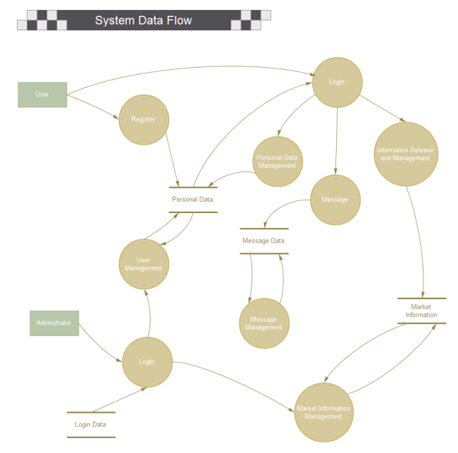
Data flow diagrams originated from their use in operational research to model workflow in organizations. DFD emanated from the Activity Diagram used in Structured Analysis and Design Technique (SADT) at the end of the 1970s. Data flow diagrams quickly became a popular way to visualize the process data and steps. Although DFDs were mainly used to show data flow in computer systems, they quickly became useful in documenting significant data flows.
If you want to know how to create data flow diagram with a handy tool,a step-by-step video tutorial is ready for you. Watch this out!
Before you embark on creating a data flow diagram, it is important to determine what suits your needs between a physical and a logical DFD.
Physical DFD focuses on how things happen by specifying the files, software, hardware, and people involved in an information flow.
Logical DFD focuses on the transmitted information, entities receiving the information, the general processes that occur, etc. It describes the business activities but doesn't delve into the technical aspects of the process.
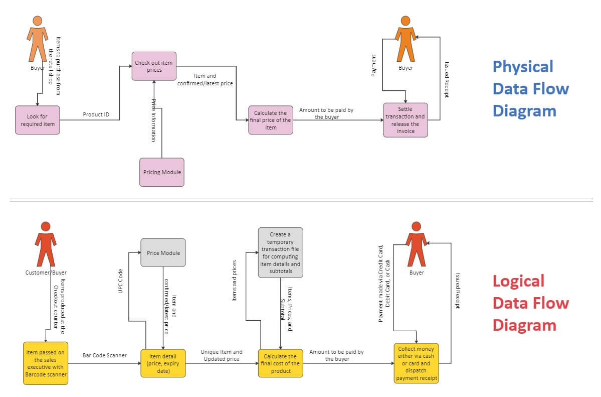
You might need both physical and logical data flow diagrams to describe the same information flow. When well-coordinated, they provide more details than each would independently.
Efficient Data Flow Diagram Maker >>
- Superior file compatibility: Import and export drawings to various file formats, such as Visio
- Cross-platform supported (Windows, Mac, Linux, Web)
DFD symbols are consistent notations that depict a system or a process. It entails the use of short-text labels, arrows, circles and rectangles to describe data flow direction. Also forming part of DFDs are varied sub-processes, data storage points, and data inputs and outputs.
A data flow diagram has four basic elements. The elements include external entities, data stores, processes, and data flows. The elements are best represented by the two main methods of notation used in DFDs – Yourdon & Coad , and Gane & Sarson . DFD symbols vary slightly depending on methodology. Even so, the basic ideas remain the same.
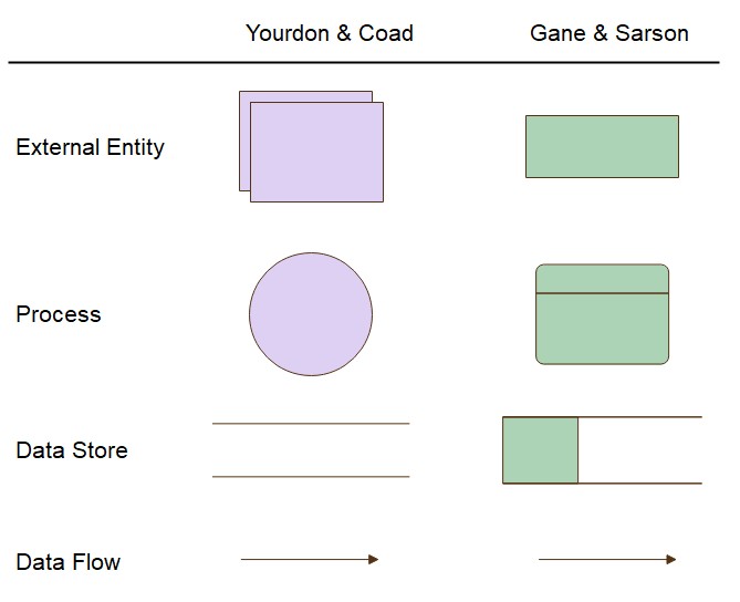
- External entities are represented by squares as the source or destination of data.
- Processes are represented by rectangles with rounded corners.
- Data Flows are referred to by arrows to denote the physical or electronic flow of data.
- Data Stores are physical or electronic-like XML files denoted by open-ended rectangles.
Data Flow Diagram

Data Flow Model Diagram

Yourdon and Coad
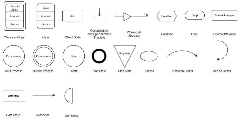
Download Data Flow Diagram Symbol Legend
Want to Create Data Flow Diagram with Pre-made Templates? Try Now!
EdrawMax Data Flow Diagram Maker offers different categories of templates in every industry, such as library management, hotel management, school, live shopping, etc... You can use pre-made templates to design your own diagram with ease! Do it now!
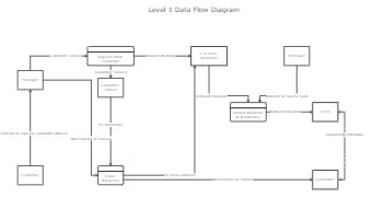
Click here to see more templates
Data Flow Diagram Notations
External Entity - An outside process or system that sends or receives data to and from the diagrammed system. They are also known as sources, terminators, sinks or actors and are represented by squares.
Process - This procedure manipulates the data by changing or processing incoming data to an output. Processes (that mainly entail input-processing-output) are portrayed by rectangles with rounded corners, which contains 3 descriptive elements:
Firstly an identification number appears in the upper left-hand corner. This is allocated arbitrarily at the top level and serves as a unique reference.
Secondly, a location appears to the right of the identifier and describes where in the system the process takes place. This may, for example, be a department or a piece of hardware. Finally, a descriptive title is placed in the center of the box. This should be a simple imperative sentence with a specific verb, such as 'maintain customer records' or 'find the driver.'
Data Store - A data store is a holding place for information within the system. It is represented by an open-ended narrow rectangle. Data stores may be long-term files such as sales ledgers or short-term accumulations: for example, batches of documents that are waiting to be processed. Each data store should be given a reference, followed by an arbitrary number.
Data Flow - A data flow shows the flow of information from its source to its destination. A data flow is represented by a line with arrowheads showing the direction of flow. Information always flows to or from a process and may be written, verbal or electronic. Each data flow may be referenced by the processes or data stores at its head and tail, or by a description of its contents.
Resource Flow - A resource flow shows the flow of any physical material from its source to its destination. For this reason, they are sometimes referred to as physical flows.
The physical material in question should be given a meaningful name. Resource flows are usually restricted to early, high-level diagrams. They are used when a description of the physical flow of materials is considered to be important to help the analysis.
To create a valid DFD, it’s important to follow the 4 rules of thumb. They offer the best guide to create data flow diagrams .
- Every single process should have at least one input and one output.
- Each data store should have at least one data flow in and data flow out.
- Every system’s stored data has to go through a process.
- Every process in a data flow diagram must link to another process or data store.
With the background information on DFDs and the rules of thumb, you can build your own DFD. The process entails the following five steps:
1. Identify the major inputs and outputs in your system
This step gives a macro view of your system and elucidates the broadest tasks the system should achieve. Again, the rest of the DFD is built on these elements.
2. Build a context diagram (Level 0 DFD)
You could achieve this by drawing a single process node and connecting it to related external entities. The node represents the general process information undergoes in a system from input to output.
3. Expand the context diagram into a level 1 DFD
Level 1 DFDs are more of a general overview, but they give more detail than a context diagram. Break the single process lump into detailed processes. This brings out where the information starts and what needs to happen to it.
4. Expand to level 2+ DFD
This breaks the processes down into more detailed subprocesses. Ensure you add any necessary data stores and flows at this point.
5. Ascertain the accuracy of your final DFD
Walk again through your diagram as you pay close attention to the flow of information. If it makes sense and all necessary data stores are included, then thumbs up. Other parties should find your diagram comprehensible.
Data Flow Diagram (DFD) Examples
Let’s see how these symbols used in the data flow diagram. You can create a clear data flow diagram effectively with EdrawMax !
1. Sales Data Flow Template
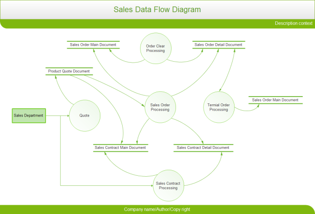
2. Warehouse Data Flow Diagram Template
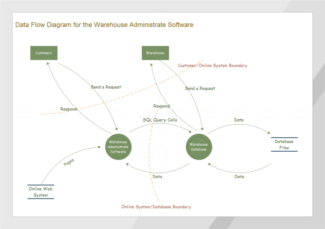
3. Train Tickets Reservation DFD
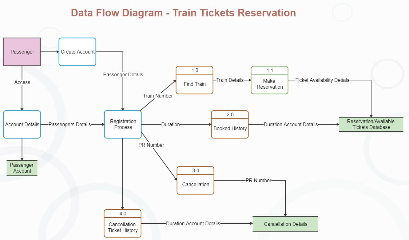
Businesses are built on systems and processes without which they'd prove challenging to operate. How team members interact with the systems significantly affects process efficiencies.
Data flow diagrams provide essential information about a system's input, output, and processes, and countless insights on analyzing and improving efficiency. Whether you're improving an existing process or implementing a new one, a DFD will make your task easier. You could download relevant templates from EdrawMax and create your own DFD.
More Related
How to Create a Data Flow Diagram
DFD Examples
Get Started! You Will Love This Easy-To-Use Diagram Software
EdrawMax is an advanced all-in-one diagramming tool for creating professional flowcharts, org charts, mind maps, network diagrams, UML diagrams, floor plans, electrical diagrams, science illustrations, and more. Just try it, you will love it!
- Software Engineering Tutorial
- Software Development Life Cycle
- Waterfall Model
- Software Requirements
- Software Measurement and Metrics
- Software Design Process
- System configuration management
- Software Maintenance
- Software Development Tutorial
- Software Testing Tutorial
- Product Management Tutorial
- Project Management Tutorial
- Agile Methodology
- Selenium Basics
Types and Components of Data Flow Diagram (DFD)
- What is DFD(Data Flow Diagram)?
- Levels in Data Flow Diagrams (DFD)
- Difference between Flowchart and Data Flow Diagram (DFD)
- Rules for Data Flow Diagram
- Data Flow Diagram for Online Banking System
- Component Based Diagram
- Use Case Diagram for Online Banking System
- Data Marts (storage component of HDFS)
- Data Communication - Definition, Components, Types, Channels
- Components of Data Communication System
- ER Diagram of a Company
- Connected Components in an Undirected Graph
- Spatial Data Types and Models
- Diagrammatic and Graphic Presentation of Data
- Types of Diagrams
- How to Convert ER Diagrams to Tables in DBMS?
- Types of 2-D discrete data plots in MATLAB
- Package Diagram | Introduction, Elements, Use Cases and Benefits
- Conversion of Block Diagrams into Signal Flow Graphs
Data Flow Diagrams (DFDs) are powerful visual tools representing information flow within systems. Understanding their types and components is important as each type has a different purpose, and components help in creating an accurate Data Flow Diagram (DFD).
Table of Content
What is Data Flow Diagram (DFD)
Types of Data Flow Diagram (DFD)
Components of Data Flow Diagram
Frequently asked questions on types and components of data flow diagram (dfd).
Data Flow Diagram (DFD) is a graphical representation of data flow in any system. It is capable of illustrating incoming data flow, outgoing data flow, and stored data. Data flow diagram describes anything about how data flows through the system.
Sometimes people get confused between a data flow diagram and a flowchart. There is a major difference between a data flow diagram and a flowchart. The flowchart illustrates flow of control in program modules. Data flow diagrams illustrate the flow of data in the system at various levels. The data flow diagram does not have any control or branch elements.
.webp)
There are two types of Data Flow Diagram (DFD)
- Logical DFD
- Physical DFD
Logical Data Flow Diagram
Logical data flow diagram mainly focuses on the system process. It illustrates how data flows in the system. In the Logical Data Flow Diagram (DFD), we focus on the high-level processes and data flow without delving into the specific implementation details. Logical DFD is used in various organizations for the smooth running of system. Like in a Banking software system, it is used to describe how data is moved from one entity to another.
When to use Logical Data Flow Diagram
Logical Data Flow Diagram are mostly used during the requirement analysis phase, user communication, and high-level system design
- Requirement Analysis: Logical Data Flow Diagram plays a important role during Requirement analysis. It provides a clear understanding of data flow between end-user, processes and data warehouse without getting deep into technical terminology. They help in identifying what the system needs to do and how data moves within the system.
- User Communication: Logical Data Flow Diagram is very useful communication tools between system analyst and end users. It provide a clear understanding of system requirements and functionalities to non-technical stakeholders.
- High-Level System Design: Logical Data Flow Diagram helps in creating a high level system design for the system’s architecture . Logical Data Flow focus on processes and data flow that helps in the further development of software.
Why Logical DFDs
Logical Data Flow Diagram provide Abstraction from Technical Details, Clarity and Simplicity and excellent tools for user communication.
- Abstraction from Technical Details: Logical Data Flow Diagram (DFD) provides a abstraction to complex model i.e. DFD hides unnecessary implementation details and show only the flow of data and processes within information system.
- Clarity and Simplicity: Logical Data Flow Diagram provides clarity and simplicity as it uses symbols and notation for data flow, data store, processes and external entity that can be easy understand by stakeholders.
- User Communication: Logical Data Flow Diagram is very useful communication tools between system analyst and end users.
.webp)
Logical Data Flow Diagram of Grocery Store
Physical Data Flow Diagram (DFD)
Physical data flow diagram shows how the data flow is actually implemented in the system. In the Physical Data Flow Diagram (DFD), we include additional details such as data storage, data transmission, and specific technology or system components. Physical DFD is more specific and close to implementation.
Physical Data Flow Diagrams (DFDs) are used in the following situations:
- Detailed Design Phase: Physical DFDs are helpful during the detailed design phase of a system. Logical DFD provide system processes and data flow at higher level of abstraction while physical DFD provides a more detailed view of data flow and processes within the information system.
- Implementation Planning: Physical DFD helps developer during Implementation planning as it provides a detailed view of how data flow within the system’s physical components, such as hardware devices, databases, and software modules. Physical DFD helps the developers in identifying the correct technologies and resources required to implement the system.
- Integration with Existing Systems: Physical DFD are important for understanding data flow when integrating a new system with existing systems or external entities,
- Documentation and Maintenance: Physical DFDs can be referred as documentation for system architecture and data flow patterns, that helps in system maintenance and troubleshooting.
Why Physical DFDs
Physical Data Flow Diagram provides Implementation Guidance and also helps in performance optimization.
- Implementation Guidance: Physical Data Flow Diagram provide Implementation Guidance as it provide a clear understanding of how data is flow within physical component of system. This helps the developers in identifying the correct technologies and resources required to develop and deploy the system.
- Performance Optimization: Physical DFDs are used to optimize system performance by identifying potential bottlenecks and inefficiencies in data processing. By visualizing the physical flow of data, system architects and developers can streamline processes, reduce processing times, and improve overall system efficiency.
.webp)
Following are the components of the data flow diagram that are used to represent source, destination, storage and flow of data.
- External Entity: External entity also known as Terminator, Actor, is the component of Data flow Diagram (DFD) that stands outside of the system and communicates with the system. It can be, for example, organizations like banks, groups of people like customers or different departments of the same organization, which is not a part of the model system and is an external entity. Modeled systems also communicate with terminator.
- Process: Input to output transformation in a system takes place because of process function. The symbols of a process are rectangular with rounded corners, oval, rectangle or a circle. The process is named a short sentence, in one word or a phrase to express its essence
- Data Flow: Data flow describes the information transferring between different parts of the systems. The arrow symbol is the symbol of data flow. A relatable name should be given to the flow to determine the information which is being moved. Data flow also represents material along with information that is being moved. Material shifts are modeled in systems that are not merely informative. A given flow should only transfer a single type of information. The direction of flow is represented by the arrow which can also be bi-directional.
- Warehouse (Data Store) : The data is stored in the warehouse for later use. Two horizontal lines represent the symbol of the store. The warehouse is simply not restricted to being a data file rather it can be anything like a folder with documents, an optical disc, a filing cabinet. The data warehouse can be viewed independent of its implementation. When the data flow from the warehouse it is considered as data reading and when data flows to the warehouse it is called data entry or data updating.
What symbols and notations are used to represent Components of DFD?
In Data-Flow Diagrams (DFDs), symbols and notations vary depending on the methodology being used. Here’s a summary of symbols and notations commonly associated with each methodology:
The different methodologies or approaches used for creating Data-Flow Diagrams (DFDs) are:
- Gane and Sarson
- Yourdon and De Marco
Each methodology provides its own set of guidelines, symbols, and notations for representing system components and their interactions.

Methods and Symbols of Component of Data Flow Diagram
Data Flow Diagram ( DFD) are visual maps that provides a clear understanding of how information moves within a information system. There are two types of Data Flow Diagrams (DFD) that are physical and logical DFD. Logical DFDs provides a clear understanding of system functionality and high-level data flows, that helps in requirement analysis, user communication, and high-level system design. On the other hand, Physical DFDs provide a detailed view of how data is flow and processed within the system’s physical components. Data Flow Diagram (DFD) consist of four component i.e. Processes that represent system’s functionality, External Entities that represent the end users, data store that represent database or data ware house and data flow that represent how data are flow among these three components.
What are the components of a DFD?
Four Components of DFD are: Process Data Flow Data Store External Entity
What are the features of DFD?
DFD helps us to understand the functioning and the limits of a system. DFD is a graphical representation which is very easy to understand as it helps visualize contents.
What are the objectives of DFD?
The main objectives of Data Flow Diagrams (DFDs) are to visually represent how data moves through a system and to help stakeholders understand system requirements and functionalities in a clear, straightforward manner.
What is Level 3 DFD?
Level 3 DFD is the the most detailed level of DFDs, which provides a detailed view of the processes, data flows, and data stores in the system.
Please Login to comment...
Similar reads.
- Software Engineering
Improve your Coding Skills with Practice
What kind of Experience do you want to share?
- Digital transformation
To help companies large and small get more out of their business processes, this comprehensive guide to BPM explains what it is, its benefits, the challenges it poses and best practices for using it effectively. You'll also find examples of business process automation and process improvement projects, an overview of the latest BPM tools and insight on what the future of BPM might look like. Throughout the guide, there are hyperlinks to related articles that cover these topics in more depth, so be sure to click on them for additional expert advice. The links also connect readers to detailed definitions of important concepts in BPM, such as business process mapping, Business Process Model and Notation (BPMN) and workflow management.
Top business process modeling techniques with examples, business process modeling techniques and tools provide a visual representation of processes that's crucial to effectively monitoring, improving and streamlining the flow of tasks..
- Kathleen Walch, Cognilytica
- Ronald Schmelzer, Cognilytica
All businesses have a range of processes with varying degrees of complexity that typically require multiple steps and activities managed by different departments and groups. Although these processes are vital to how businesses operate and compete, they often aren't properly mapped and documented, creating ambiguity, bottlenecks and inefficiencies that can hamper an organization's agility and decision-making.
To successfully map a process , it's important to first understand the composition of a business process, the need to document all the steps in the process , and the various modeling techniques and business process modeling tools available.
What is a business process?
A business process comprises a sequence of steps that flow in a specific order to achieve a desired outcome. Business process modeling provides an approach to mapping and representing those key steps in a visual manner to highlight how they flow together. Modeling systems are a tool for designing business processes and a method to capture a real-time view of what's going on, showing how all steps, activities, tasks and processes fit together.
Mapping, modeling, and improving business processes are facets of business process management , a structured approach for optimizing the processes organizations use to get work done, serve their customers and generate business value. Modeling tools give managers a way to identify, characterize and illustrate the entire business process from start to finish. Effective business process management and modeling increases the awareness and understanding of the many processes in an enterprise.
This article is part of
What is business process management? A guide to BPM
- Which also includes:
- How AI is radically changing business process management
- 10 trends shaping the future of BPM in 2024
- 12 top business process management tools for 2024
Why do companies have business process modeling?
Modeling business processes is vital for two reasons. One is to identify the processes that already exist in the organization ("as is" processes) so they can be improved, automated and optimized. Another is to identify processes that need to be implemented ("should be" processes) to achieve critical business outcomes.
Business process modeling has been essential to businesses for many decades, and organizations have found success in applying modeling techniques and tools. While modeling systems are intended to be visual, they're often accompanied by varying degrees of documentation to provide greater detail when necessary.
The concept of process modeling might seem somewhat simple to grasp, but performing modeling activities can be a challenge. Often, many departments, roles and relationships are involved, making relatively simple tasks seem more complex once they're mapped.
Mapping and modeling a business process can provide many benefits :
- Assists with understanding exactly what activities need to occur and in what sequence to readily pinpoint potential delays, redundancies and opportunities for improvement.
- Enables analysis of the entire process and individual tasks so they can be continuously monitored and improved.
- Eases communication among stakeholders concerning process issues, especially for complex workflows .
- Locates bottlenecks disrupting processes as well as identifies and incorporates tasks that are being skipped or missed in the process.
- Isolates which tasks and processes can be automated to significantly increase efficiency and streamline tedious, repetitive and perhaps dangerous tasks so employees can focus on higher-value, higher-skilled work.
Business process modeling technique examples
Many process modeling techniques have been developed over the decades to support specific business needs. With so many options available, it's important to know and understand nine of the more commonly used modeling techniques, keeping in mind that not every modeling technique is right for every process.
1. Gantt charts
Named after American mechanical engineer and management consultant Henry Gantt, these charts have been actively used for more than a century to visualize process flows. Gantt charts use a bar style that illustrates a project schedule, including the duration of tasks, any dependencies, key milestones and areas of task interdependence. They're most often used in situations with specific deadlines or time-sensitive processes.
Despite their vintage, Gantt charts are still among the more popular and useful methods to show and track activities, tasks or events during certain periods of time. Processes and activities can be tracked and recorded in a sequential, easy-to-understand view clearly showing when tasks begin and end. These charts are most widely used by project managers to provide a single view, monitor tasks and keep all parties on track.
One major limitation is the simplistic approach to task visualization that can't easily accommodate subtasks -- process flows that can branch in multiple directions or tasks that repeat.
2. Flowcharts
Flowcharts visualize how a set of steps can progress in a variety of ways, using simple shapes and arrows to show each step in a process and how they interconnect. They are commonly used for graphic representations of process modeling and map the progression of actions to reach a specific outcome. They're most useful when they show straightforward business processes that generally operate in a sequential manner.
Flowcharts don't show parallel processes working in sync well, making them almost too simple for many modern business processes.
3. Data flow diagrams
Data flow diagrams (DFDs) provide a more specific visualization of data streams, detailing specific actions than can be represented in a flowchart. DFDs are best suited to display the progression of how data enters and flows through a system as well as how data is stored. They also provide visualizations and representations of flows like flowcharts but are more specifically focused on the data that flows between process steps rather than the operations of those activities.
The DFD's data-centricity presents limitations for non-data-driven projects and doesn't easily accommodate different collaborators and stakeholders in the process.
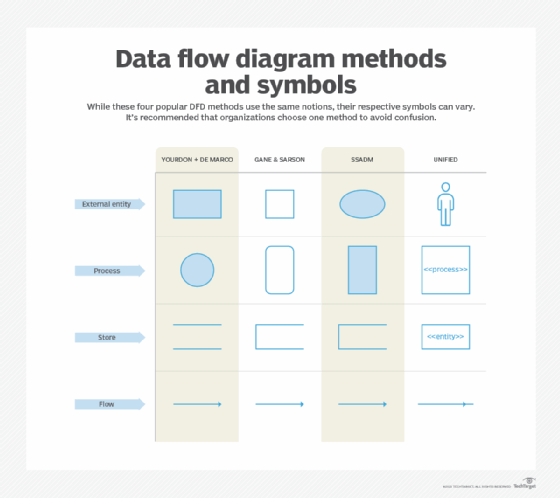
4. Business Process Modeling Notation
Business Process Modeling Notation (BPMN) encompasses a set of more than 100 standardized symbols or objects that visually represent various workflows and tasks in business processes. This technique was created specifically for modeling and is considered by many as the gold standard for business process modeling. Due to its standardized notation, BPMN provides unambiguous elements to diagram and display the flow of processes while avoiding communication gaps.
Companies might choose to enhance BPMN with their own symbols and visual language. But using standardized BPMN is recommended for outside collaboration to save time and effort when working with third parties. The following are some of BPMN's basic symbols:
- Flow objects visually show the flow of the process.
- Connecting objects display how tasks are connected and in what sequence they occur.
- Swim lanes show how responsibilities are shared and distributed among different groups, people or departments. The subtask is the "pool" and the "lanes" represent people or departments.
- Artifacts explain a process.
5. Unified Modeling Language diagrams
Unified Modeling Language ( UML ) diagrams were initially created by software developers to visualize systems design and interactions in a standardized way. This technique has the following distinct types:
- Structural information represents the system's structure.
- Behavioral diagrams target the relationship between objects in a system. A subset of the behavioral diagram is the interaction diagram, which visualizes the control flow.
UML diagrams are beneficial when documenting processes in software programs. But with 14 UML diagram types, this approach can be difficult to understand without a strong knowledge of UMLs.
6. Functional flow block diagrams
With origins stretching back decades, functional flow block diagrams (FFBDs) have proven valuable for business process mapping. These diagrams use a sequential order of blocks to show the tasks needed for a desired outcome. Each "parent" block can be broken into subtasks or "children" for each task in the process, so the diagrams can be easily summarized.
FFBDs are an improvement over flowcharts when representing nested functionality. But multiple blocks are required to showcase a single process, which can create a need for several diagrams.
7. Integrated definition for function modeling
Integrated definition for function modeling (IDEF) diagrams are used to model functions for business processes in which a "parent" action leads to "child" diagrams, as is the case with FFBDs. But IDEFs are far more complex. They can specify more detailed functionality, show function interdependency, and are particularly useful in mapping object-oriented and service-oriented flows.
There are 15 types of IDEFs that focus on specific flows for data, information and functions. Being inherently complex is both their greatest asset and a major limitation.
8. Petri nets and Colored Petri nets
Though somewhat esoteric, Petri nets are often used to model and analyze business process workflows. They provide a distinctive technique for mapping business processes and borrow from concepts such as Markov processes and Markov state diagrams that show transitions from one state to another. Unlike flowcharts, Petri Nets are best suited for mapping processes in which several subprocesses must be synchronized or occur simultaneously.
Petri nets can also represent a state, such as waiting or unsent, and an action, such as send, receive or transmit, in the same diagram. They can identify when processes are stalled in specific states or if there are potential undesired looping conditions. A closely related technique, Colored Petri nets use colors to discern symbols or objects, making them well-suited for a system that has numerous processes interacting and synchronizing with one another.
These techniques, however, require a big learning curve. The mathematical representation is complex and demands specific knowledge to test and deploy the diagrams.
9. Role activity diagrams
Role activity diagrams (RADs) are powerful tools used in the analysis and design of business processes. RADs focus on the activities performed by different roles within an organization. They visually map out the workflow and interactions between various roles, highlighting the sequence of actions and the flow of information. RADs facilitate a clear understanding of responsibilities and dependencies in a process, making them invaluable for optimizing operations and enhancing collaboration across teams.
10. Role interaction diagrams
Different from RADs, role interaction diagrams visually depict interactions among processes. RADs come in two versions.
- Sequence diagrams show the chronological order of interactions in a system.
- Collaboration diagrams are used to depict the interactions of specific objects in a flow.
These diagrams display the sequential and parallel aspects of a given business process. They are used to determine interfaces and class responsibilities.
Start from the beginning
While it's important to understand the various business process modeling techniques, getting started is a whole other issue. Select a process in greatest need of improvement, map all the steps in the process flow using business process management methods , and diagram and document the entire process visually using the selected modeling technique. Business process modeling can then spot potential delays, redundancies and opportunities for much-needed improvement in the process.
How to set business goals, step by step
How to improve and optimize business processes, step by step
Top trends shaping the future of BPM
Top business process management tools
Related Resources
- How do we build trust in the digital world Video –Okta
- Enable Deep Visibility for Applications, Users, and Devices With FortiGate ... –Fortinet, Inc.
- ITSM Problem Management: What Are Your Pain Points? –ServiceNow
- Time to rekindle the Digital Transformation drive –TechTarget ComputerWeekly.com
Dig Deeper on Digital transformation

business process modeling

entity relationship diagram (ERD)

data modeling

Business Process Model Notation (BPMN)
Is it better to be 'first' or 'smart' in cloud? Compare the two strategies to determine which will help achieve your ...
Consistency and standardization are critical to a successful AWS tagging strategy. Consider these best practices to organize and ...
Serverless computing continues to grow in popularity to build modern applications. Evaluate the risks and rewards, as well as ...
Mobile payments provide customers with a fast and secure way to pay without cash or physical cards. Managing these systems can be...
Mobile payment systems can vary in terms of their fees, setup process and functionality. Organizations must know how to choose ...
To succeed with enterprises, pricing for Copilot+ PC will have to come down for high-volume sales and business software will need...
A main focus of the Dell Technologies World 2024 conference was AI and how it impacts infrastructure environments. Dell ...
In this Q&A, Dell's Matt Baker lays out how its AI Factory is designed for faster AI adoption, why there are so many chatbots and...
An incredible amount of research must go into data center site selection. If the location does not fit company demands, the data ...
Dell Technologies World 2024 showcased hardware advancements to support AI and served as a launch for Apex AIOps, a rebranded ...
The best ESG and sustainability certification, workshop or course is the one that is right for you. Here are seven that work for ...
With so many carbon accounting software choices, buying teams may be overwhelmed. Start with this simplified guide to the ...
Advisory boards aren’t only for executives. Join the LogRocket Content Advisory Board today →

- Product Management
- Solve User-Reported Issues
- Find Issues Faster
- Optimize Conversion and Adoption
A guide to user flow diagrams

As a product manager, you’re responsible for ensuring that you create a functional product with an intuitive user journey. To help you accomplish this, you can use a user flow diagram to visualize how users interact with your product in each stage. This will allow you to see the way users move through your product and come to a better understanding of the user decision-making process.
User flow diagrams also enable you to streamline navigation, remove pain points, and create a more engaging experience.
In this article, you will learn what a user flow diagram is, the different types of user flows, and how you create and implement them within your team.
What is a user flow diagram?
A user flow diagram is a visual representation of a user’s journey through your product. It shows the sequence of actions that a user takes from their initial interaction all the way through to their end goal.
User flow diagrams are usually used by product managers and UX designers to better understand and improve the user experience. The diagrams help to identify pain points and areas of confusion to make informed decisions about functionality.
3 types of user flow diagrams
According to the NN Group , user flows can be represented in three ways:
Task diagrams
Wireflows are a visual representation of the screens in an app, alongside their user interactions. They can vary from very low fidelity (see example below) to high fidelity screens with arrows linking them. Wireflows provide an overview of all the interactions on a screen, where they lead, and any decision points:
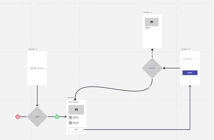
A flowchart is “a diagram of the sequence of movements or actions of people or things involved in a complex system or activity (Oxford Languages).” It shows a user’s journey through an application, including business logic and alternate flows. They can be used to map out flows inside an application, but also to map business processes:
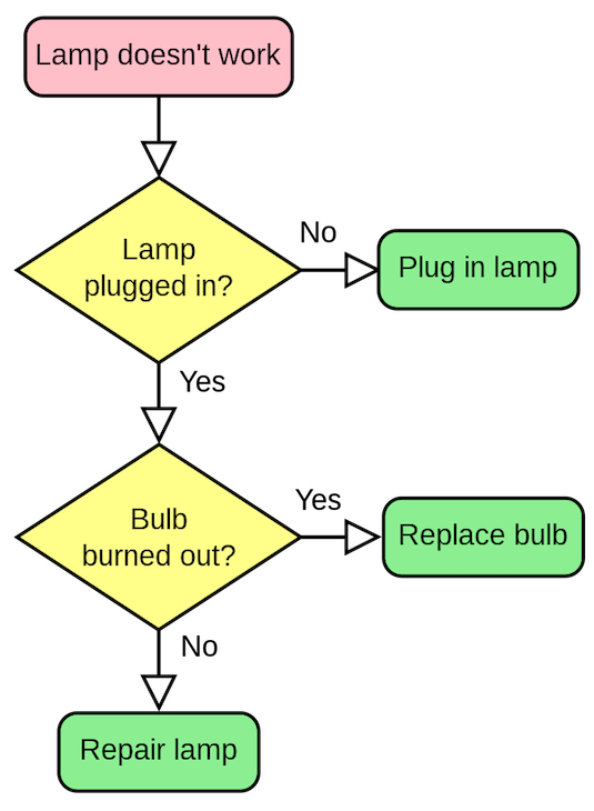
Key components of a flowchart
When creating a flowchart for a product, use the following elements:
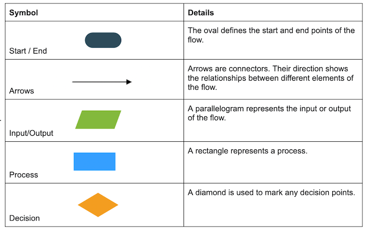
Task diagrams are similar to flow charts, but they represent a single task within a larger path. Because of this, you can think of a task diagram as a subset of a flowchart. A task diagram utilizes the same components as a flowchart.
Benefits of user flow diagrams
User flow diagrams allow you to:
- Describe how the user interacts with the product
- Avoid missing steps or inconsistencies in the process
- Gain shared understanding and validation
- Identify pain points
A user flow diagram shows how the user interacts with the product to achieve a goal. You can use flows to understand existing applications, especially when you want to create a new product or a new feature.
User flow diagrams help you identify any inconsistencies or dead ends early in the process. By mapping out your user flow (either through a wireflow or through a flowchart), you make sure you don’t have any dead ends.

Over 200k developers and product managers use LogRocket to create better digital experiences
User flow diagrams are very useful for validating your concepts and aligning stakeholders.
The development team can better understand your concept and determine your interactions on the page. Subject matter experts can review your process and ensure that everything is in the correct order with the right conditions.
You can also use user flow diagrams to analyze situations and identify pain points and improvement opportunities. At any point in the journey you might notice that users consistently pause over a particular issue, or that they need more assistance to progress forward.
User flow diagram example
Now let’s walk through an example to better understand how you can create a user flow diagram in practice. Say you want to define the user flow for an application that allows friends from different banks to split bills, facilitating a seamless and secure money transfer. The steps would look like:
- Define the user persona
- Determine the user goal
- Set the entry point
- Map out the steps the user takes to achieve the goal
- Revisit and identify alternate flows
- Sketch the wireframes and add arrows for the interactions
- Communicate the results
1. Define the user persona
You should conduct user research and base your persona on actual data and pain points.
For this scenario, you’re looking at an individual who frequently shares expenses with friends and wants a convenient way to split bills, even if their friends are at different banks.
2. Determine the user goal
The user’s goal here is to initiate a bill split with a friend from a different bank and transfer the funds securely.
3. Set the entry point
In this case, the entry point would be to open the app. The user would trigger this because they need to split a bill.
4. Map out the steps the user takes to achieve the goal
To achieve the goal, the user will need to navigate through the following:
- Open the app and navigate to the split bill feature
- Enter the total amount of the bill to be split
- Select the option to split with a friend from a different bank
- Enter the friend’s bank account details, such as bank name, account number, and routing number
- Verify the entered bank account details for accuracy
- Confirm the split and initiate the fund transfer
- Receive a confirmation of the successful transfer
5. Revisit and identify alternate flows
Once you map out the flow, try to come up with any alternative steps that could come into play, such as:
- Friend verification — After entering the friend’s bank account details, the app could prompt the user to verify the friend’s identity to ensure the accuracy of the information. This verification step can be done through various means, such as sending a verification code to the friend’s registered email or phone number
- Error handling for incorrect bank details — If the user enters incorrect bank account details for their friend, the app can provide an error message specifying the issue and offer suggestions on how to correct the information. This may involve prompting the user to double-check the account number, routing number, or bank name
- Request confirmation from a friend — In specific scenarios, the app might send a request to a friend at a different bank, asking them to confirm the bill split. The friend would receive a notification or message with the details of the split and an option to accept or decline the request. This step adds an extra layer of confirmation and consent from the friend before proceeding with the transaction
6. Sketch the wireframes and add arrows for the interactions
To create a wireflow, you want to sketch the wireframes at this stage. After you have all the screens, use arrows to show their interactions.
While a UX designer can provide more detail, here are the screens we could have for this flow:
- Split bill feature in the app’s main menu
- Bill split form with an input field for the total amount
- Friend selection screen with an option to choose a friend at a different bank
- Bank account details entry screen with fields for bank name, account number, and routing number
- Verification screen showing the entered bank account details for confirmation
- Confirmation screen with a success message and transaction details
7. Communicate the results
Once the flow is complete, you can share it with your stakeholders to receive feedback. Try to identify areas of improvement and work to optimize the user experience.
The user flow diagram for this example would look like:
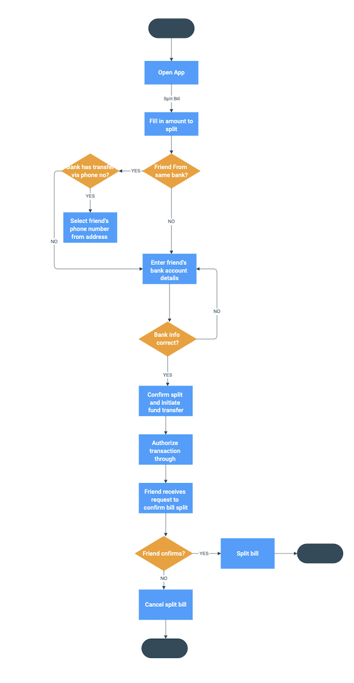
Tools for creating user flow diagrams
There are a variety of tools to help you create user flows. Here are a few that also have free versions:
- Lucid chart
Final thoughts
User flow diagrams are powerful tools to help you validate concepts and identify pain points. They allow you to fail fast with minimum effort and ensure that you build the right thing for your users.
By using user flow diagrams, you can:
You can follow the example included in this article to build out a user flow diagram for your own product.
Featured image source: IconScout
LogRocket generates product insights that lead to meaningful action
Get your teams on the same page — try LogRocket today.
Share this:
- Click to share on Twitter (Opens in new window)
- Click to share on Reddit (Opens in new window)
- Click to share on LinkedIn (Opens in new window)
- Click to share on Facebook (Opens in new window)
- #product strategy
- #tools and resources

Stop guessing about your digital experience with LogRocket
Recent posts:.

Leader Spotlight: Creating dynamic product content, with Nacho Nart
Nacho Nart talks about using modify existing product assets, such as photos and advertisements, to cater to different geographies and markets.

What makes for a habit-forming product?
The job of the product is to get that first win to establish trust and then create a loop with nudges for further engagement.

Leader Spotlight: Gaining context in new industries and verticals, with Boris Logvinsky
Boris Logvinsky talks about the importance of building context and understanding customer challenges when you move between industries.

Techniques for running customer behavior analysis
Customer behavior analysis (CBA) is the study of how individual customers, groups, or segments act when interacting with your product.

Leave a Reply Cancel reply
Data flow diagram: Level 0
Explore our level 0 data flow diagram. It's a context diagram that helps map out the flow of information to better visualize processes and systems.
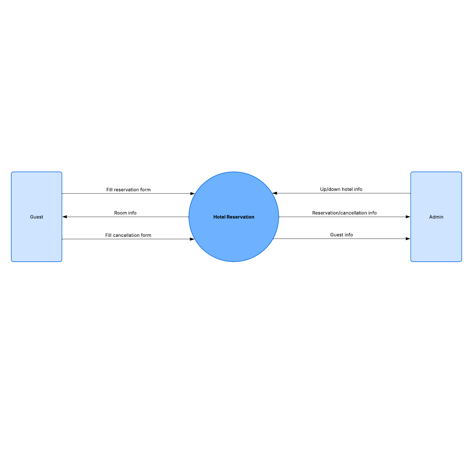
Visualize the flow of information with a data flow diagram
Within any digital process or system, information must move in more than one direction. This may be a simple back-and-forth (like filling out an online quiz), or a more complicated process involving several data entry points, like buying merchandise through a third-party seller.
In any case, those who want to improve or build such systems must keep track of what information is needed, where that information comes from, and where it needs to go. If you need to map out a system in this way, one simple yet effective method is to use a data flow diagram.
Data flow diagrams use simple symbols and notes to map how the data moves in a particular system. System designers can use these diagrams to create new systems or to catch any discrepancies or bottlenecks in existing systems. Maintaining a clear picture of where the data flows can save money, increase efficiency, and improve user experience.
Lucidchart offers a simple, customizable data flow diagram that you can use as a resource for your entire team. It can be updated with existing data in real time and accessed anytime and anywhere, which makes it ideal for remote teams.
Use the Data flow diagram: Level 0 in Lucidchart
You can use our data flow diagram example as-is or add more shapes and lines to represent a more complex system. Here are some tips to get you started:
- To format shapes as you’d like, click on a shape and then click "Shape Options" to select the fill or line colors.
- To add lines, hover over a shape and click on any red circle. To format lines, use the properties bar at the top of the canvas.
- To add text to a line, double-click existing text, or anywhere on the line, and start typing.
- To import data from another source to use in your template, click on "Import Data" on the bottom left.
For more tips on optimizing your template, click on the buttons to the right of the document to access more in-depth tutorials and information on data flow diagrams. Take advantage of all the template offers to keep track of data in your current and future projects.
Related templates

System landscape

Service desk flowchart with Dynamic Shapes example

Example of perform test activities

Facility quality control example

IMAGES
VIDEO
COMMENTS
A data flow diagram (DFD) is a visualization that maps out the sequence of information, actors, and steps within a process or system. It uses a set of defined symbols that each represent the people and processes needed to correctly transmit data within a system. Data flow diagrams are most often used to visually represent the flow of data ...
A data flow diagram (DFD) maps out the flow of information for any process or system. It uses defined symbols like rectangles, circles and arrows, plus short text labels, to show data inputs, outputs, storage points and the routes between each destination. Data flowcharts can range from simple, even hand-drawn process overviews, to in-depth ...
A data-flow diagram is a way of representing a flow of data through a process or a system ... The refined representation of a process can be done in another data-flow diagram, which subdivides this process into sub-processes. The data-flow diagram is a tool that is part of structured analysis and data modeling. When using UML, ...
Graphical Representation: Data Flow Diagram (DFD) use different symbols and notation to represent data flow within system.That simplify the complex model. Problem Analysis: Data Flow Diagram (DFDs) are very useful in understanding a system and can be effectively used during analysis. Data Flow Diagram (DFDs) are quite general and are not limited to problem analysis for software requirements ...
A data flow diagram shows the way information flows through a process or system. It includes data inputs and outputs, data stores, and the various subprocesses the data moves through. DFDs are built using standardized symbols and notation to describe various entities and their relationships. Data flow diagrams visually represent systems and ...
What is Data Flow Diagram? Also known as DFD, Data flow diagrams are used to graphically represent the flow of data in a business information system. DFD describes the processes that are involved in a system to transfer data from the input to the file storage and reports generation. Data flow diagrams can be divided into logical and physical.
Introduction. Data Flow Diagrams (DFDs) serve as a time-tested and traditional visual representation, offering a comprehensive insight into the intricate web of information flows within a system.This graphical tool is instrumental in illustrating how data navigates through the various facets of an information system, encompassing processes, data storage, and the generation of reports.
A data flow diagram shows how data is processed within a system based on inputs and outputs. Visual symbols are used to represent the flow of information, data sources and destinations, and where data is stored. Data flow diagrams are often used as a first step toward redesigning a system. They provide a graphical representation of a system at ...
Draw data flow diagrams can be made in several nested layers. A single process node on a high level diagram can be expanded to show a more detailed data flow diagram. Draw the context diagram first, followed by various layers of data flow diagrams. DFD Levels. The first level DFD shows the main processes within the system.
A data flow diagram (or DFD) is a graphical representation of the information flow in a business process. It demonstrates how data is transferred from the input to the file storage and reports generation. By visualizing the system flow, the flow charts will give users helpful insights into the process and open up ways to define and improve ...
A data flow diagram (DFD) is a visual representation of the information flow through a process or system. DFDs help you better understand process or system operations to discover potential problems, improve efficiency, and develop better processes. They range from simple overviews to complex, granular displays of a process or system.
A Data Flow Diagram (DFD) is defined as a graphical representation of the flow of data within a system. It illustrates how data moves from input sources, through various processes, and finally to output destinations. DFDs are commonly used in systems analysis and design to visualize and understand the data flow and processes within a system.
1. Introduction. A data flow diagram (DFD) is a graphical representation of data flow through a system. It's employed to understand how data is processed, stored, and communicated within a system. Moreover, DFD is used to support the analysis of how the data flows in existing or proposed systems from one page or module to another (using a ...
A Data Flow Diagram (DFD) is a traditional way to visualize the information flows within a system. A neat and clear DFD can depict a good amount of the system requirements graphically. It can be manual, automated, or a combination of both. It shows how information enters and leaves the system, what changes the information and where information ...
Step 4: Expand your context diagram into a level 1, 2, or 3 DFD. You'll need to break down your context diagram to reveal the details of your main systems. A level 1, 2, or 3 DFD will do just that—take the example below. To do this, simply add and connect elements to your subprocesses and -systems.
A data flow diagram (DFD) is a graphical or visual representation using a standardized set of symbols and notations to describe a business's operations through data movement. They are often elements of a formal methodology such as Structured Systems Analysis and Design Method ( SSADM ). Superficially, DFDs can resemble flow charts or Unified ...
A data flow diagram (DFD) is a visual map that shows how data moves through a system or a process. It uses symbols like arrows, rectangles, circles, and text labels to represent data flow or transmission. A DFD lets you trace information from the source to the destination. It is commonly used in software development, especially in creating and ...
Context data flow diagram (also called Level 0 diagram) uses only one process to represent the functions of the entire system. It does not go into details as marking all the processes. The purpose is to express the system scope at a high level as well as to prevent users from deep down into complex details.
Data Flow Diagram Notations. External Entity - An outside process or system that sends or receives data to and from the diagrammed system. They are also known as sources, terminators, sinks or actors and are represented by squares. Process - This procedure manipulates the data by changing or processing incoming data to an output. Processes (that mainly entail input-processing-output) are ...
1. Select a data flow diagram template. In the Documents section, click on the orange +Document button and double-click on the Blank ERD & Data Flow diagram. 2. Name the data flow diagram. Click on the Blank ERD & Data Flow header in the top left corner of the screen.
Data Flow Diagram (DFD) is a graphical representation of data flow in any system. It is capable of illustrating incoming data flow, outgoing data flow, and stored data. Data flow diagram describes anything about how data flows through the system. Sometimes people get confused between a data flow diagram and a flowchart.
Data flow diagrams. Data flow diagrams (DFDs) provide a more specific visualization of data streams, detailing specific actions than can be represented in a flowchart. DFDs are best suited to display the progression of how data enters and flows through a system as well as how data is stored. ... Petri nets can also represent a state, such as ...
Task diagrams. Task diagrams are similar to flow charts, but they represent a single task within a larger path. Because of this, you can think of a task diagram as a subset of a flowchart. A task diagram utilizes the same components as a flowchart. Benefits of user flow diagrams. User flow diagrams allow you to:
A data flow diagram tool allows you to take any flow of information for a process or system and condense it into a coherent, easily understood visual. PINGDOM_CANARY_STRING ... DFDs provide a detailed representation of components within a system and how they interact. This helps viewers understand how a process or system currently works, or how ...
Data flow diagrams use simple symbols and notes to map how the data moves in a particular system. System designers can use these diagrams to create new systems or to catch any discrepancies or bottlenecks in existing systems. ... You can use our data flow diagram example as-is or add more shapes and lines to represent a more complex system ...