- Agile project management
- Waterfall Methodology

Waterfall Methodology: A Comprehensive Guide
Browse topics.
If you've been in project management for a while, you must’ve encountered the Waterfall methodology. It's an old-school software development method from the 1970s.
In a Waterfall process, you must complete each project phase before moving to the next. It's pretty rigid and linear. The method relies heavily on all the requirements and thinking done before you begin.
Don't worry if you haven't heard of it. Let’s break the Waterfall method down and see how it works.
What is the Waterfall methodology?
Waterfall methodology is a well-established project management workflow . Like a waterfall, each process phase cascades downward sequentially through five stages (requirements, design, implementation, verification, and maintenance).
The methodology comes from computer scientist Winston Royce’s 1970 research paper on software development. Although Royce never named this model “waterfall”, he gets credit for creating a linear, rigorous project management system.
Unlike other methods, such as the Agile methodology, Waterfall doesn't allow flexibility. You must finish one phase before beginning the next. Your team can’t move forward until they resolve any problems. Moreover, as our introduction to project management guide outlines, your team can’t address bugs or technical debt if it’s already moved on to the next project phase.
What are the stages of the Waterfall methodology?
Five phases comprise the Waterfall methodology: requirements, design, implementation, verification, and maintenance. Let's break down the five specific phases of Waterfall development and understand why it’s critical to complete each phase before progressing to the next.
Requirements
The requirements phase states what the system should do. At this stage, you determine the project's scope, from business obligations to user needs. This gives you a 30,000-foot overview of the entire project. The requirements should specify:
- resources required for the project.
- what each team member will work on and at what stage.
- a timeline for the entire project, outlining how long each stage will take.
- details on each stage of the process.
But these requirements " may range from very abstract to a detailed mathematical specification ,” writes Steven Zeil , professor of computer science at Old Dominion University. That’s because requirements might not outline an exact implementation, and that’s something development addresses in later stages.
After gathering all the requirements, it's time to move on to the design stage. Here, designers develop solutions that meet the requirements. In this stage, designers:
- create schedules and project milestones.
- determine the exact deliverables.
- create designs and/or blueprints for deliverables.
Deliverables could include software or they could consist of a physical product. For instance, designers determine the system architecture and use cases for software. For a physical product, they figure out its exact specifications for production.
Implementation
Once the design is finalized and approved, it's time to implement it. Design hands off their specifications to developers to build.
To accomplish this, developers:
- create an implementation plan.
- collect any data or research needed for the build.
- assign specific tasks and allocate resources among the team.
Here is where you might even find out that parts of the design that can't be implemented. If it's a huge issue, you must step back and re-enter the design phase.
Verification
After the developers code the design, it’s time for quality assurance. It’s important to test for all use cases to ensure a good user experience. That's because you don't want to release a buggy product to customers.
- writes test cases.
- documents any bugs and errors to be fixed.
- tests one aspect at a time.
- determines which QA metrics to track.
- covers a variety of use case scenarios and environments.
Maintenance
After the product release, devs might have to squash bugs. Customers let your support staff know of any issues that come up. Then, it's up to the team to address those requests and release newer versions of your product.
As you can see, each stage depends on the one that comes before it. It doesn't allow for much error between or within phases.
For example, if a stakeholder wants to add a requirement when you're in the verification phase, you'll have to re-examine the entirety of your project. That could mean tossing the whole thing out and starting over.
Benefits of Waterfall methodology
The benefits of Waterfall methodology have made it a lasting workflow for projects that rely on a fixed outcome. A 2020 survey found that 56% of project professionals had used traditional, or Waterfall, models in the previous year.
A few benefits of Waterfall planning include:
- Clear project structure : Waterfall leaves little room for confusion because of rigorous planning. There is a clear end goal in sight that you're working toward.
- Set costs : The rigorous planning ensures that the time and cost of the project are known upfront.
- Easier tracking : Assessing progress is faster because there is less cross-functional work. You can even manage the entirety of the project in a Gantt chart, which you can find in Jira.
- A replicable process : If a project succeeds, you can use the process again for another project with similar requirements.
- Comprehensive project documentation : The Waterfall methodology provides you with a blueprint and a historical project record so you can have a comprehensive overview of a project.
- Improved risk management : The abundance of upfront planning reduces risk. It allows developers to catch design problems before writing any code.
- Enhanced responsibility and accountability : Teams take responsibility within each process phase. Each phase has a clear set of goals, milestones, and timelines.
- More precise execution for a non-expert workforce : Waterfall allows less-experienced team members to plug into the process.
- Fewer delays because of additional requirements : Since your team knows the needs upfront, there isn't a chance for additional asks from stakeholders or customers.
Limitations of Waterfall methodology
Waterfall isn't without its limitations, which is why many product teams opt for an Agile methodology.
The Waterfall method works wonders for predictable projects but falls apart on a project with many variables and unknowns. Let's look at some other limitations of Waterfall planning:
- Longer delivery times : The delivery of the final product could take longer than usual because of the inflexible step-by-step process, unlike in an iterative process like Agile or Lean.
- Limited flexibility for innovation : Any unexpected occurrence can spell doom for a project with this model. One issue could move the project two steps back.
- Limited opportunities for client feedback : Once the requirement phase is complete, the project is out of the hands of the client.
- Tons of feature requests : Because clients have little say during the project's execution, there can be a lot of change requests after launch, such as addition of new features to the existing code. This can create further maintenance issues and prolong the launch.
- Deadline creep : If there's a significant issue in one phase, everything grinds to a halt. Nothing can move forward until the team addresses the problem. It may even require you to go back to a previous phase to address the issue.
Below is an illustration of a project using the waterfall approach. As you can see, the project is segmented into rigid blocks of time. This rigidity fosters an environment that encourages developers, product managers, and stakeholders to request the maximum amount of time allotted in each time block, since there may be no opportunity to iterate in the future.
How is the Waterfall method different from Agile project management?
Agile project management and the Waterfall methodology have the same end goal: crystal clear project execution. While Waterfall planning isolates teams into phases, Agile allows for cross-functional work across multiple phases of a project. Instead of rigid steps, teams work in a cycle of planning, executing, and evaluating, iterating as they go.
The " Agile Manifesto " explains the benefits of Agile over the Waterfall model:
- Individuals and interactions over processes and tools
- Working software over comprehensive documentation
- Customer collaboration over contract negotiation
- Responding to change by following a plan
If you're looking for tools that support Agile project management and serve the same end goal as Waterfall, consider Jira . It’s best suited for Agile projects, and helps you:
- Track work : With Gantt charts , advanced roadmaps , timelines, and various other tools, you can easily track your progress throughout the project.
- Align your team : Tracking allows you to seamlessly plan across business teams, keeping everyone aligned on the same goals.
- Manage projects and workflows : With Jira, you can access project management templates that you can use for your Agile workflows .
- Plan at every stage : Jira Product Discovery , another product by Atlassian, offers product roadmaps for planning and prioritizing product features at every stage, from discovery to delivery.
Atlassian's Agile tools support the product development lifecycle. There are even Agile metrics for tracking purposes. Jira lets you drive forward the Agile process. It uses intake forms to track work being done by internal teams and offers a repeatable process for requests.
These Jira products integrate natively within the app, unifying teams so they can work faster.
Use Agile methodology for project management
Waterfall methodology has a long history in project management, but it's often not the right choice for modern software developers. Agile methodology offers greater flexibility.
Here’s why most teams prefer an Agile process:
- Adaptability to changes : If something arises, your team will be better able to adjust on the fly. Waterfall’s rigidity makes it difficult to deal with any roadblocks.
- Continuous feedback loop : Continuous improvement requires a feedback loop. With Agile, you can gather feedback from stakeholders during the process and iterate accordingly.
- Stronger communication : Teams work collaboratively in an Agile process. Waterfall is a series of handoffs between different teams, which hinders effective communication.
Here is where a project management tool such as Jira comes in handy for an Agile methodology. You can also use a project management template for your Agile projects. Your team can plan, collaborate, deliver, and report on projects in one tool. That keeps everyone aligned throughout any project and streamlines project management.
Waterfall methodology: Frequently asked questions
Who is best suited for waterfall methodology.
The Waterfall methodology works best for project managers working on projects that include:
- Less complex objectives : Projects that don't have complicated requirements are best suited for Waterfall.
- Predictable outcomes : Waterfall works best for those projects that are replicable and proven.
- Reduced likelihood of project scope creep : A project where clients aren't likely to come up with last-minute requirements is suitable for Waterfall.
Agile methodology is perfect for nimble teams with an iterative mindset, such as:
- Cross-functional teams : A team of people with different skill sets that allows them to work on various aspects of a project. These are collaborative types who are flexible.
- Self-organizing teams : Autonomous teams that don't need a lot of handholding. They embrace ambiguity in a project and are great problem solvers. This mindset also gives them more ownership over outcomes.
- Startups and small businesses : These benefit from the mindset of " move fast and break things ". So they can fail fast, learn, and improve.
Finally, Agile works well for customer-centric projects where their input allows you to iterate.
What factors should I consider before implementing a project management approach?
When deciding on the proper methodology to implement in project management, there are four main factors to consider: project complexity, organizational goals, team expertise, and stakeholder involvement.
Let’s break each one down:
- Project complexity : Waterfall can help break down larger, more complex projects into smaller sets of expectations and goals. But its rigidity doesn’t deal well with unknowns or changes. Agile is better for complex projects that have a lot of variables.
- Organizational goals : What does your organization want to achieve? Is it looking to innovate or keep the status quo? An Agile approach is best if your organization wants to break down silos. Teams will work more collaboratively with more autonomy.
- Team expertise : Agile is an excellent way to go if your team is cross-functional and can work across skill sets. If your team members rely heavily on a singular skill set, Waterfall may be better.
- Stakeholder involvement : If your stakeholders are going to be more hands-on, Agile will help you best because it allows for continuous feedback and iteration.
Get started building an agile workflow
Agile process flows help bring structure to scale your software development process. Learn more about workflow management to support your agile program.
Agile vs. waterfall project management
Agile project management is an incremental and iterative practice, while waterfall is a linear and sequential project management practice

Examples Of The Waterfall Model
Anjali works at a technology firm where she’s been assigned to lead a team to deliver an elaborate software program…

Anjali works at a technology firm where she’s been assigned to lead a team to deliver an elaborate software program within a very tight schedule. At first, Anjali tries to coordinate with her associates and create her own model. But as the pressure mounts, her model crumbles and the entire team is rattled.
Anjali spends a couple of days researching solutions and discovers the waterfall model. She goes through the waterfall model in detail and distributes the responsibilities for the project among several departments, based on the different phases of the model.
As the project requires utmost stability, Anjali creates a blueprint and a timeline that aren’t subject to change and feeds them into the waterfall model. Thereafter, the model takes care of everything. With a strict schedule for delivery in place and all departmental roles neatly assigned, the waterfall model brings the project to a close one week ahead of time and in the smoothest manner possible.
Anjali’s success becomes another excellent example of the waterfall model doing what it does best.
What Is The Waterfall Model?
When is the waterfall model used, how to explain the waterfall model with examples, solutions at your fingertips.
Before proceeding to explain the waterfall model with examples, let’s go over the basics of the waterfall model and what exactly it’s supposed to achieve.
The waterfall model was one of the first models to be introduced in project management. As a linear or sequential model, the waterfall model has a number of phases, each of which must be completed before moving onto the next one. This is why the model is known as the waterfall model because its movement from one phase to another in a downward manner similar to a waterfall.
For smooth functioning, the waterfall model uses the output from one phase as input for the next phase. At the end of each phase, you’re supposed to carry out a review to find out if the project is on the right path or whether it needs to be discarded and restarted.
The term “waterfall” was used for the first time in a 1976 paper co-authored by Thomas Bell and Thomas Thayer to describe their model. However, the first formal and detailed diagram of the model had been published before, in an article in 1970 written by Winston Royce. Royce’s article was largely critical of the waterfall model, particularly on how testing of the model could only be performed at the end of the process.
The waterfall model that you’re likely to come across today includes seven phases, which are listed as follows:
Recruitment Gathering
System Design
Implementation
Integration And Testing
Deployment Of System
Maintenance Or Fixing Issues
Nowadays, the waterfall model is one of several models that are frequently used for project management. Other models include iterative and agile models, which are much more flexible as compared to the waterfall approach.
In order to understand a real-life example of the waterfall model, let’s familiarize ourselves with situations when the waterfall model is usually used:
When the project requirements are laid down at the outset and remain more or less fixed throughout the entire process
When the product definition is stable and a lot of information is required before completing each phase
In cases where a strict timeline needs to be prepared and followed, without alterations
In sectors involving engineering design and software development that generally demand project management on a large scale
In manufacturing and construction industries, where design changes are usually very costly
In the closing decades of the 20th century, the waterfall model was used primarily to develop enterprise applications like Human Resource Management Systems (HRMS), Supply Chain Management Systems, Customer Relationship Management (CRM) systems, Inventory Management Systems, Point of Sales (POS) systems for retail chains, etc. The model was also extremely popular in software development.
With the evolution of technology, there were cases where large-scale enterprise systems, with the waterfall model as the default choice, were developed over a period of two to three years but became redundant by the time they were completed. Slowly, these enterprise systems switched over to more flexible and less expensive models, but the waterfall model continued to be preferred in systems where:
A human life is at stake and a system failure could result in fatalities
Money and time are secondary factors and what matters more is the safety and stability of a project
Military and aircraft programs where requirements are declared early on and remain constant
Projects with an extremely high degree of oversight and/or accountability such as those in the sectors of banking, healthcare and control systems for nuclear facilities
Now that you’ve grasped the several sectors in which the waterfall model used to be and is still deployed, here is a real-life example of the waterfall model at work.
Here, the waterfall model is used to manufacture a tractor, with each of its phases outlining the work that needs to be done. Before moving to the phases, however, the organization manufacturing the tractor would need to carry out a feasibility study, including planning the budget and adding new features to the tractor that’ll put it ahead of other tractors in the market.
Thereafter, the following phases (only including the most important ones) take over:
This phase of the waterfall model is used to determine the speed, mileage, engine specifications, color and seat requirements of the tractor to be manufactured.
This phase is concerned with developing and designing the frame material, the exterior and interior body quality and material as well as the tyre quality for the tractor.
Implementation:
This phase brings together the two previous phases by combining all the pre-decided features and actually manufacturing the tractor.
This phase is all about trying out the tractor under various circumstances and conditions, from evaluating its performance on different types of roads and weather conditions to checking its durability, fuel consumption and the amount of heat it produces.
Maintenance:
The final phase is about offering regular services to preserve the quality of the tractor and make whatever repairs or adjustments are necessary.
Let’s look at another real-life example of the waterfall model, where the different phases have been used to manufacture and deliver a software program that relies on university rankings and student scores to determine which universities and courses are best suited for students opting for an undergraduate degree.
As with the previous example of the waterfall model, the organization designing the software program needs to perform a feasibility study to find out what kind of programs are already present in the market that can achieve similar tasks in academia. Following this, the most important phases of the waterfall model can start functioning as follows:
This phase will be tasked with gathering all the information available on student scores and university rankings and devising the different parameters that’ll be used for determining a university’s suitability for a student.
In this example of the waterfall model, the design phase is all about fine-tuning the parameters established in the analysis phase and making sure that the structure of the software program is precise enough to avoid any manipulation of or confusion over large volumes of data.
This all-important phase involves doing dummy runs of the software program with a provisional set of data to see the accuracy with which the program can suggest appropriate universities for students. These suggestions should then be matched with results obtained from academic counselors who have arrived at the suggestions through their years of professional expertise.
As with any example of the waterfall model, the testing phase is about ensuring that all features of the software program function smoothly and that there are no glitches that can derail the utility of the overall program.
In the final phase, the software program should be checked for any necessary updates or alterations that may be required, besides the expected inclusion of new data, including a greater volume of student scores and a fresh set of university rankings.
The waterfall model is just one example of the many approaches adopted in project management . At Harappa, the Executing Solutions course is tailor-made for you to master several approaches, such as the Branding, Leadership And Selling Techniques ( BLAST ) approach (on how to develop a mindset for devising responsible solutions), the Bifocal Approach (a strategy that balances short-term and long-term views).
With the help of a world-class faculty, this course will allow you to closely monitor your progress, navigate crises, scrutinize frameworks and develop a holistic approach to managing all kinds of projects. Sign up for the Executing Solutions course today and join employees from organizations like NASSCOM, Uber and Standard Chartered in elevating your management skills.
Explore Harappa Diaries to learn more about topics such as How Does The Waterfall Model Help In Project Management, Advantages & Disadvantages Of Waterfall Model , What Is Project Management , Introduction To Operations Management & How To Do A PERT Analysis and monitor your projects efficiently.

- Product overview
- All features
- App integrations
CAPABILITIES
- project icon Project management
- Project views
- Custom fields
- Status updates
- goal icon Goals and reporting
- Reporting dashboards
- workflow icon Workflows and automation
- portfolio icon Resource management
- Time tracking
- my-task icon Admin and security
- Admin console
- asana-intelligence icon Asana Intelligence
- list icon Personal
- premium icon Starter
- briefcase icon Advanced
- Goal management
- Organizational planning
- Campaign management
- Creative production
- Content calendars
- Marketing strategic planning
- Resource planning
- Project intake
- Product launches
- Employee onboarding
- View all uses arrow-right icon
- Project plans
- Team goals & objectives
- Team continuity
- Meeting agenda
- View all templates arrow-right icon
- Work management resources Discover best practices, watch webinars, get insights
- What's new Learn about the latest and greatest from Asana
- Customer stories See how the world's best organizations drive work innovation with Asana
- Help Center Get lots of tips, tricks, and advice to get the most from Asana
- Asana Academy Sign up for interactive courses and webinars to learn Asana
- Developers Learn more about building apps on the Asana platform
- Community programs Connect with and learn from Asana customers around the world
- Events Find out about upcoming events near you
- Partners Learn more about our partner programs
- Support Need help? Contact the Asana support team
- Asana for nonprofits Get more information on our nonprofit discount program, and apply.
Featured Reads

- Project management |
- Guide to waterfall methodology: Free te ...
Guide to waterfall methodology: Free template and examples

Waterfall project management is a sequential project management methodology that's divided into distinct phases. Each phase begins only after the previous phase is completed. This article explains the stages of the waterfall methodology and how it can help your team achieve their goals.
But what if your project requires a more linear approach? Waterfall methodology is a linear project management methodology that can help you and your team achieve your shared goals—one task or milestone at a time. By prioritizing tasks and dependencies, the waterfall method helps keep your project on track.
What is waterfall methodology?
Waterfall methodology, a term coined by Dr. Winston W. Royce in 1970, is a sequential design process used in software development and product development where project progress flows steadily downwards through several phases—much like a waterfall. The waterfall model is structured around a rigid sequence of steps that move from conception, initiation, analysis, design, construction, testing, implementation, and maintenance.
Unlike more flexible models, such as Agile, the waterfall methodology requires each project phase to be completed fully before the next phase begins, making it easier to align with fixed budgets, timelines, and requirements.
By integrating comprehensive documentation and extensive upfront planning, waterfall methodology minimizes risk and tends to align well with traditional project management approaches that depend on detailed records and a clear, predetermined path to follow.
For example, here’s what a waterfall project might look like:

The waterfall methodology is often visualized in the form of a flow chart or a Gantt chart. This methodology is called waterfall because each task cascades into the next step. In a Gantt chart, you can see the previous phase "fall" into the next phase.
6 phases of the waterfall project management methodology
Any team can implement waterfall project management, but this methodology is most useful for processes that need to happen sequentially. If the project you’re working on has tasks that can be completed concurrently, try another framework, like the Agile methodology .
If you’re ready to get started with the waterfall methodology, follow these six steps:
1. Requirements phase
This is the initial planning process in which the team gathers as much information as possible to ensure a successful project. Because tasks in the waterfall method are dependent on previous steps, it requires a lot of forethought. This planning process is a crucial part of the waterfall model, and because of that, most of the project timeline is often spent planning.
To make this method work for you, compile a detailed project plan that explains each phase of the project scope. This includes everything from what resources are needed to what specific team members are working on the project. This document is commonly referred to as a project requirements document.
By the end of the requirements phase, you should have a very clear outline of the project from start to finish, including:
Each stage of the process
Who’s working on each stage
Key dependencies
Required resources
A timeline of how long each stage will take.
A well-crafted requirements document serves as a roadmap for the entire project, ensuring that all stakeholders are on the same page.
2. System design phase
In a software development process, the design phase is when the project team specifies what hardware the team will be using, and other detailed information such as programming languages, unit testing, and user interfaces. This phase of the waterfall methodology is key to ensuring that the software will meet the required functionality and performance metrics.
There are two steps in the system design phase: the high-level design phase and the low-level design phase. In the high-level design phase, the team builds out the skeleton of how the software will work and how information will be accessed. During the low-level design phase, the team builds the more specific parts of the software. If the high-level design phase is the skeleton, the low-level design phase is the organs of the project.
Those team members developing using the waterfall method should document each step so the team can refer back to what was done as the project progresses.
3. Implementation phase
This is the stage where everything is put into action. The team starts the full development process to build the software in accordance with both the requirements phase and the system design phase, using the requirements document from step one and the system design process from step two as guides.
During the implementation phase, developers work on coding and unit testing to ensure that the software meets the specified requirements.
4. Testing phase
This is the stage in which the development team hands the project over to the quality assurance testing team. QA testers search for any bugs or errors that need to be fixed before the project is deployed.
Testers should clearly document all of the issues they find when QAing. In the event that another developer comes across a similar bug, they can reference previous documentation to help fix the issue.
5. Deployment phase
For development projects, this is the stage at which the software is deployed to the end user. For other industries, this is when the final deliverable is launched and delivered to end customers. A successful deployment phase requires careful planning and coordination to ensure a smooth rollout.
6. Maintenance phase
Once a project is deployed, there may be instances where a new bug is discovered or a software update is required. This is known as the maintenance phase, and it's common in the software development life cycle to be continuously working on this phase.
Regular maintenance and updates are essential for keeping the software running smoothly and addressing any issues that arise post-deployment.
When to use waterfall methodology
The waterfall methodology is a common form of project management because it allows for thorough planning and detailed documentation. However, this framework isn’t right for every project. Here are a few examples of when to use this type of project management.
Project has a well-defined end goal
One of the strengths of the waterfall approach is that it allows for a clear path from point A to point B. If you're unsure of what point B is, your project is probably better off using an iterative form of project management like the Agile approach.
Projects with an easily defined end goal are well-suited for waterfall methodology because project managers can work backwards from the goal to create a clear and detailed path with all of the requirements necessary.
No restraints on budget or time
If your project has no restraints on budget or time, team members can spend as much time as possible in the requirements and system design phases. They can tweak and tailor the needs of the project as much as they want until they land on a well-thought-out and defined project plan.
Creating repeatable processes
The waterfall model requires documentation at almost every step of the process. This makes it easy to repeat your project for a new team member; each step is clearly detailed so you can recreate the process.
Creating repeatable processes also makes it easy to train new team members on what exactly needs to be done in similar projects. This makes the waterfall process an effective approach to project management for standardizing processes.
Waterfall vs. Agile methodologies
While the waterfall methodology follows a linear, sequential approach, Agile is an iterative and incremental methodology. In Agile, the project is divided into smaller, manageable chunks known as sprints. Each sprint includes planning, design, development, testing, and review phases.
The Agile method emphasizes flexibility, collaboration, and rapid iteration based on continuous feedback. It allows for changes and adaptations throughout the project's lifecycle. In contrast, the waterfall model has a more rigid structure with distinct phases and limited room for changes once a phase is complete.
The choice between waterfall and Agile depends on factors such as project complexity, clarity of requirements, team size, and client involvement. The waterfall model is suitable for projects with well-defined requirements and minimal changes expected, while the Agile method is favored for projects with evolving requirements and a need for frequent client feedback and course corrections.
Benefits of waterfall methodology
Consistent documentation makes it easy to backtrack.
When you implement the waterfall project management process, you’re creating documentation every step of the way. This can be beneficial—if your team needs to backtrack your processes, you can easily find mistakes. It's also great for creating repeatable processes for new team members, as mentioned earlier.
Tracking progress is easy
By laying out a waterfall project in a Gantt chart, you can easily track project progress. The timeline itself serves as a progress bar, so it’s always clear what stage a project is in.
![[Old Product UI] Mobile app launch project in Asana (Timeline)](https://assets.asana.biz/transform/a5f7977a-e36d-43fb-89e9-ca12b741ca11/inline-visual-project-management-kanban-timeline-calendar-2-2x?io=transform:fill,width:2560&format=webp "waterfall approach case study")
Team members can manage time effectively
Because the waterfall methodology requires so much upfront planning during the requirement and design phase, it is easy for stakeholders to estimate how much time their specific part of the waterfall process will take.
Downsides of waterfall project management
Roadblocks can drastically affect timeline.
The waterfall methodology is linear by nature, so if there's a bump in the road or a task gets delayed, the entire timeline is shifted. For example, if a third-party vendor is late on sending a specific part to a manufacturing team, the entire process has to be put on hold until that specific piece is received.
Linear progress can make backtracking challenging
One of the major challenges of the waterfall methodology is that it's hard to go back to a phase once it's already been completed. For example, if someone is painting the walls of a house, they wouldn’t be able to go back and increase the size of one of the rooms.
QA is late in the process
In comparison to some of the more iterative project management methodologies like Kanban and Agile, the review stage in a waterfall approach happens later in the process. If a mistake is made early on in the process, it can be challenging to go back and fix it. Because of how the waterfall process works, it doesn’t allow for room for iteration or searching for the best solution.
Waterfall methodology examples
To better understand how the waterfall methodology is applied in practice, let's look at a couple of real-world use cases:
1. Construction Project: Building a new office complex requires careful planning and sequential execution. The project manager first gathers all the requirements, such as building specifications, timelines, and budgets. Then, architects and engineers create detailed designs. After approval, construction starts and strict quality controls follow. Finally, the building is handed over to the client for use and maintenance.
2. Software Engineering Project: A company wants to develop a new mobile application using the software development life cycle (SDLC). The project manager defines the product requirements, including features, performance metrics, and integrations. Software architects create the high-level design and technical specifications. Developers then follow the SDLC phases of coding, unit testing, and deployment. The team follows the waterfall methodology throughout the product development process, making sure that each step is finished before going on to the next. After the successful launch, the mobile app enters the maintenance phase, where the team addresses user feedback and provides updates.
Managing your waterfall project
With waterfall projects, there are many moving pieces and different team members to keep track of. One of the best ways to stay on the same page is to use project management software to keep workflows, timelines, and deliverables all in one place.
If you're ready to try waterfall project management with your team, try a template in Asana . You can view Asana projects in several ways, including Timeline view, which visualizes your project as a linear timeline.
FAQ: Waterfall methodology
How do you handle changes in requirements during a waterfall project?
Handling changes in requirements during a waterfall project can be challenging, but it's essential to assess the impact of the change, communicate with stakeholders, update project documentation, adjust the project plan, and ensure all team members are informed of the changes. Implementing a change control process can help formally manage and track changes throughout the project.
Can you combine waterfall and agile methodologies in a single project?
Yes, it is possible to combine waterfall and agile methodologies in a single project using a hybrid approach. This involves using waterfall methodology for the upfront planning and requirements gathering phases and adopting agile practices during the implementation and testing phases. The balance between the waterfall model and Agile method can be adjusted based on the project scope.
How do you ensure successful team collaboration on a waterfall project?
Ensuring successful team collaboration in a waterfall project involves establishing clear communication, defining roles and responsibilities, scheduling regular meetings, using collaborative tools, fostering a positive team culture, and providing necessary support and resources. By focusing on these key aspects, teams can work together effectively and efficiently to achieve project goals.
What are the best project management tools for waterfall methodology?
For teams following a waterfall methodology, Asana is the best project management tool available. Its comprehensive set of features, such as Timeline view for visualizing project plans, task dependencies for ensuring proper sequencing, and seamless integrations, make it the ideal choice for managing linear projects. While other tools like Microsoft Project offer waterfall-specific features, Asana's ease of use, collaboration capabilities, and flexibility make it the top choice for teams looking to streamline their waterfall project management process.
Related resources

What is a flowchart? Symbols and types explained

What are story points? Six easy steps to estimate work in Agile

How to choose project management software for your team

7 steps to complete a social media audit (with template)
- SUGGESTED TOPICS
- The Magazine
- Newsletters
- Managing Yourself
- Managing Teams
- Work-life Balance
- The Big Idea
- Data & Visuals
- Reading Lists
- Case Selections
- HBR Learning
- Topic Feeds
- Account Settings
- Email Preferences
It’s Time to End the Battle Between Waterfall and Agile
- Antonio Nieto-Rodriguez

A hybrid approach can get the best out of both project management methodologies.
Too many project leaders think rigidly about Waterfall and Agile project management methodologies and believe that they need to choose between the two. But many projects — especially those with diverse stakeholder needs and complex structures — benefit from a hybrid approach that combines aspects of Waterfall and Agile. The rise of hybrid methods isn’t tied to a particular time or event; instead, they have evolved organically as a response to the needs of modern, complex projects. A review of the key components of Waterfall and Agile allows project leaders to select among them to build a hybrid approach based on the unique demands of each project.
When you are leading a high-stakes project, choosing between the rigor of Waterfall and the flexibility of Agile can make or break your initiative. For the last two decades, too many academics, leaders, project managers, and organizations have thought they have to choose one or the other. Worse, the emergence of Agile methods led to tribalism in the project community, stifling innovation and limiting the potential for truly effective solutions.
- Antonio Nieto-Rodriguez is the author of the Harvard Business Review Project Management Handbook , five other books, and the HBR article “ The Project Economy Has Arrived. ” His research and global impact on modern management have been recognized by Thinkers50. A pioneer and leading authority in teaching and advising executives the art and science of strategy implementation and modern project management, Antonio is a visiting professor in seven leading business schools and founder of Projects & Co mpany and co-founder Strategy Implementation Institute and PMOtto . You can follow Antonio through his website , his LinkedIn newsletter Lead Projects Successfully , and his online course Project Management Reinvented for Non–Project Managers .
Partner Center
- Contact sales
- Start free trial
The Ultimate Guide…
Waterfall Model
Brought to you by projectmanager, the online project planning tool used by over 35,000 users worldwide..

What Is the Waterfall Methodology in Project Management?
The phases of the waterfall model, waterfall software development life cycle.
- What Is Waterfall Software?
- Desktop vs Online Waterfall Software
Must-Have Features of Waterfall Software
- The Waterfall Model & ProjectManager.com
Waterfall vs. Agile
- Pros & Cons of the Waterfall Model
Benefits of Project Management Software for Waterfall Projects
Waterfall methodology resources.
The waterfall methodology is a linear project management approach, where stakeholder and customer requirements are gathered at the beginning of the project, and then a sequential project plan is created to accommodate those requirements. The waterfall model is so named because each phase of the project cascades into the next, following steadily down like a waterfall.
It’s a thorough, structured methodology and one that’s been around for a long time, because it works. Some of the industries that regularly use the waterfall model include construction, IT and software development. As an example, the waterfall software development life cycle, or waterfall SDLC, is widely used to manage software engineering projects.
Related: 15 Free IT Project Management Templates for Excel & Word
Gantt charts are the preferred tool for project managers working in waterfall method. Using a Gantt chart allows you to map subtasks, dependencies and each phase of the project as it moves through the waterfall lifecycle. ProjectManager’s waterfall software offers these features and more.

Manage waterfall projects in minutes with ProjectManager— learn more .
The waterfall approach has, at least, five to seven phases that follow in strict linear order, where a phase can’t begin until the previous phase has been completed. The specific names of the waterfall steps vary, but they were originally defined by its inventor, Winston W. Royce, in the following way:
Requirements: The key aspect of the waterfall methodology is that all customer requirements are gathered at the beginning of the project, allowing every other phase to be planned without further customer correspondence until the product is complete. It is assumed that all requirements can be gathered at this waterfall management phase.
Design: The design phase of the waterfall process is best broken up into two subphases: logical design and physical design. The logical design subphase is when possible solutions are brainstormed and theorized. The physical design subphase is when those theoretical ideas and schemas are made into concrete specifications.
Implementation: The implementation phase is when programmers assimilate the requirements and specifications from the previous phases and produce actual code.
Verification: This phase is when the customer reviews the product to make sure that it meets the requirements laid out at the beginning of the waterfall project. This is done by releasing the completed product to the customer.
Maintenance: The customer is regularly using the product during the maintenance phase, discovering bugs, inadequate features and other errors that occurred during production. The production team applies these fixes as necessary until the customer is satisfied.
Related: Free Gantt Chart Template for Excel
Let’s hypothesize a simple project, then plan and execute it with the waterfall approach phases that you just learned. For our waterfall software development life cycle example, we’ll say that you’re building an app for a client. The following are the steps you’d take to reach the final deliverable.
Requirements & Documents
First, you must gather all the requirements and documentation you need to get started on the app.
- Project Scope: This is one of the most important documents in your project, where you determine what the goals associated with building your app are: functional requirements, deliverables, features, deadlines, costs, and so on.
- Stakeholder Expectations: In order to align the project scope with the expectations of your stakeholders—the people who have a vested interest in the development of the app—you want to conduct interviews and get a clear idea of exactly what they want.
- Research: To better serve your plan, do some market research about competing apps, the current market, customer needs and anything else that will help you find the unserved niche your app can serve.
- Assemble Team: Now, you need to get the people and resources together who will create the app, from programmers to designers.
- Kickoff: The kickoff meeting is the first meeting with your team and stakeholders where you cover the information you’ve gathered and set expectations.
System Design
Next, you can begin planning the project proper. You’ve done the research, and you know what’s expected from your stakeholders . Now, you have to figure out how you’re going to get to the final deliverable by creating a system design. Based on the information you gathered during the first phase, you’ll determine hardware and software requirements and the system architecture needed for the project.
- Collect Tasks: Use a work breakdown structure to list all of the tasks that are necessary to get to the final deliverable.
- Create Schedule: With your tasks in place, you now need to estimate the time each task will take. Once you’ve figured that out, map them onto a Gantt chart , and diligently link dependencies. You can also add costs to the Gantt, and start building a budget.
Implementation
Now you’re ready to get started in earnest. This is the phase in which the app will be built and tested. The system from the previous phase is first developed in smaller programs known as units. Then each goes through a unit testing process before being integrated.
- Assign Team Tasks: Team members will own their tasks and be responsible for completing them, and for collaborating with the rest of the team. You can make these tasks from a Gantt chart and add descriptions, priority, etc.
- Monitor & Track: While the team is executing the tasks, you need to monitor and track their progress in order to make sure that the project is moving forward per your schedule.
- Manage Resources & Workload: As you monitor, you’ll discover issues and will need to reallocate resources and balance workload to avoid bottlenecks.
- Report to Stakeholders: Throughout the project, stakeholders need updates to show them progress. Meet with them and discuss a regular schedule for presentations.
- Test: Once the team has delivered the working app, it must go through extensive testing to make sure everything is working as designed.
- Deliver App: After all the bugs have been worked out, you’re ready to give the finished app to the stakeholders.
System Testing and Deployment
During this phase you’ll integrate all the units of your system and conduct an integration testing process to verify that the components of your app work properly together.
Once you verify that your app is working, you’re ready to deploy it.
Verification
Though the app has been delivered, the software development life cycle is not quite over until you’ve done some administrative tasks to tie everything up. This is technically the final step.
- Pay Contracts: Fulfil your contractual obligations to your team and any freelance contractors. This releases them from the project.
- Create Template: In software like ProjectManager, you can create a template from your project, so you have a head start when beginning another, similar one.
- Close Out Paperwork: Make sure all paperwork has been rubber stamped and archived.
- Celebrate: Get everyone together, and enjoy the conclusion of a successful project!
Maintenance
Of course, the nature of any software development project is that, through use by customers, new bugs will arise and must be squashed. So, past the verification stage, it’s typically expected that you will provide maintenance beyond launch. This is an ongoing, post-launch phase that extends for as long as your contract dictates.
What Is Waterfall Project Management Software?
Waterfall project management software is used to help you structure your project processes from start to finish. It allows managers to organize their tasks, sets up clear schedules in Gantt charts and monitor and control the project as it moves through its phases.

A waterfall project is broken up into phases, which can be achieved on a Gantt chart in the waterfall project management software. Managers can set the duration for each task on the Gantt and link tasks that are dependent on one another to start or finish.
While waterfall software can be less flexible and iterative than more agile frameworks, projects do change frequently—and there must be features that can capture these changes in real-time with dashboards and reports, so that the manager can clear up bottlenecks or reallocate resources to keep teams from having their work blocked. Microsoft Project is one of the most commonly used project management software, but it has major drawbacks that make ProjectManager a great alternative .
Desktop vs Online Project Management Waterfall Software
When it comes to waterfall software, you can choose from either a desktop application or online, cloud-based project management software. This might not seem to be a big issue, but there are important distinctions between these two types of offerings.
That’s because there are differences between the two applications, and knowing those differences will help you make an informed decision.
Desktop waterfall software tends to have a more expensive up-front cost, and that cost can rise exponentially if you are required to pay per-user licensing fees for every member of your team.
Online waterfall software, on the other hand, is typically paid for on a subscription basis, and that subscription is usually a tiered payment plan depending on the number of users.
Connectivity
Online software, naturally, must be connected to the internet. This means your speed and reliability can vary depending on your internet service provider. It also means that if you lose connectivity, you can’t work.
Although the difference is minor, desktop waterfall software never has to worry about connection outages.
If security is a concern, rest assured that both options are highly secure. Desktop software that operates on a company intranet is nigh impenetrable, which can provide your company with a greater sense of security.
Strides in web security, like two-factor authentication and single-sign have made online, cloud-based waterfall software far more secure. Also, online tools have their data saved to the cloud, so if you suffer a crash on your desktop that might mean the end of your work.
Accessibility
Desktops are tied to the computers they are installed to or, at best, your office’s infrastructure. That doesn’t help much if you have distributed teams or work off site, in the field, at home and so on.
Online software is accessible anywhere, any time—so long as you have an internet connection. This makes it always accessible, but even more importantly, it delivers real-time data, so you’re always working on the current state of the project.
Waterfall software helps to organize your projects and make them run smoothly. When you’re looking for the right software to match your needs, make sure it has the following features.
Keep Your Project Structured
Managing a project with the waterfall method is all about structure. One phase follows another. To break your project into these stages, you need an online Gantt chart that has a milestone feature. This indicates the date where one phase of the waterfall process stops and another begins.

Control Your Task and Schedule
The Gantt chart is a waterfall’s best friend. It organizes your tasks, sets the duration and links tasks that are dependent to keep work flowing later on. When scheduling, you want a Gantt that can automatically calculate your critical path to help you know how much float you have.

Have Your Files Organized
Waterfall projects, like all projects, collect a lot of paperwork. You want a tool with the storage capacity to hold all your documents and make them easy to find when you need them. Also, attaching files to tasks gives teams direction and helps them collaborate.

Know If You’re on Schedule
Keeping on track means having accurate information. Real-time data makes it timely, but you also need to set your baseline and have dashboard metrics and reporting to compare your actual progress to your planned progress. This makes sure you stay on schedule.

Get an Overview of Performance
Dashboards are designed to collect data and display it over several metrics, such as overall health, workload and more. This high-level view is important, so you want to have a feature that automatically calculates this data and doesn’t require you to manually input it.

Make Data-Based Decisions
Reports dive deeper into data and get more details on a project’s progress and performance. Real-time data makes them accurate. Look for ease of use—it should only take a single click to generate and share. You’ll also want to filter the results to see only what you’re interested in.

The Waterfall Model & ProjectManager
ProjectManager is an award-winning project management software that organizes teams and projects. With features such as online Gantt charts, task lists, reporting tools and more, it’s an ideal tool to control your waterfall project management.
Sign up for a free 30-day trial and follow along to make a waterfall project in just a few easy steps. You’ll have that Gantt chart built in no time!
1. Upload Requirements & Documents
Waterfall project management guarantees one thing: a lot of paperwork. All the documentation and requirements needed to address for the project can quickly become overwhelming.
You can attach all documentation and relevant files to our software, or directly on a task. Now, all of your files are collected in one place and are easy to find. Don’t worry about running out of space—we have unlimited file storage.
2. Use a Work Breakdown Structure to Collect Tasks
Getting to your final deliverable will require many tasks. Planning the waterfall project means knowing every one of those tasks, no matter how small, and how they lead to your final deliverable. A work breakdown structure is a tool to help you figure out all those steps.
To start, use a work breakdown structure (WBS) to collect every task that is necessary to create your final deliverable. You can download a free WBS template here . Then, upload the task list to our software.

3. Open in Gantt Project View
Gantt charts are essential project management tools used for planning and scheduling. They collect your tasks in one place on a timeline . From there, you can link dependencies, set milestones, manage resources and more.
In the software, open the Gantt chart view and add deadlines, descriptions, priorities and tags to each task.
4. Create Phases & Milestones
Milestones are what separates major phases in a waterfall method project. Waterfall methodology is all about structure and moving from one phase to the next, so breaking your project into milestones is key to the waterfall method.
In the Gantt view, create phases and milestones to break up the project. Using the milestone feature, determine when one task ends and a new one begins. Milestones are symbolized by a diamond on the Gantt.
5. Set Dependencies in a Gantt Chart
Dependent tasks are those that cannot start or finish until another starts or finishes. They create complexities in managing any waterfall project.
Link dependent tasks in the Gantt chart. Our software allows you to link all four types of dependencies: start-to-start, start-to-finish, finish-to-finish and finish-to-start. This keeps your waterfall project plan moving forward in a sequential order and prevents bottlenecks.
6. Assign From Gantt Charts
Although you’ve planned and scheduled a project, it’s still just an abstraction until you get your team assigned to execute those tasks. Assigning is a major step in managing your waterfall project and needs to happen efficiently.
Assign team members to tasks right from the Gantt chart. You can also attach any related images or files directly to the task. Collaboration is supported by comments at the task level. Anyone assigned or tagged will get an email alert to notify them of a comment or update.

7. Manage Resources & Workload
Resources are anything you need to complete the project. This means not only your team, but also the materials and tools that they need. The workload represents how many tasks your team is assigned, and balancing that work keeps them productive.
Keep track of project resources on the Workload view. See actual costs, and reallocate as needed to stay on budget. Know how many tasks your team is working on with easy-to-read color-coded charts, and balance their workload right on the page.

8. Track Progress in Dashboard & Gantt
Progress must be monitored to know if you’re meeting the targets you set in your waterfall method plan. The Gantt shows percentage complete, but a dashboard calculates several metrics and shows them in graphs and charts.
Monitor your project in real time and track progress across several metrics with our project dashboard . We automatically calculate project health, costs, tasks and more and then display them in a high-level view of your project. Progress is also tracked by shading on the Gantt’s duration bar.
9. Create Reports
Reporting serves two purposes: it gives project managers greater detail into the inner-workings of their waterfall project to help them make better decisions, and acts as a communication tool to keep stakeholders informed.
Easily generate data-rich reports that show project variance, timesheets , status and more. Get reports on your planned vs. the actual progress. Filter to show just the information you want. Then, share with stakeholders during presentations and keep everyone in the loop.
10. Duplicate Plan for New Projects
Having a means to quickly copy projects is helpful in waterfall methodology, as it jumpstarts the next project by recreating the major steps and allowing you to make tweaks as needed.
Create templates to quickly plan any recurring waterfall projects. If you know exactly what it takes to get the project done, then you can make it into a template. Plus, you can import proven project plans from MSP, and task lists from Excel and Word.
The waterfall methodology is one of two popular methods to tackle software engineering projects; the other method is known as Agile .
It can be easier to understand waterfall when you compare it to Agile. Waterfall and Agile are two very different project management methodologies , but both are equally valid, and can be more or less useful depending on the project.
Waterfall Project Management
If the waterfall model is to be executed properly, each of the phases we outlined earlier must be executed in a linear fashion. Meaning, each phase has to be completed before the next phase can begin, and phases are never repeated—unless there is a massive failure that comes to light in the verification or maintenance phase.
Furthermore, each phase is discrete, and pretty much exists in isolation from stakeholders outside of your team. This is especially true in the requirements phase. Once the customer’s requirements are collected, the customers cease to play any role in the actual waterfall software development life cycle.
Agile Project Management
The agile methodology differs greatly from the waterfall approach in two major ways; namely in regards to linear action and customer involvement. Agile is a nimble and iterative process, where the product is delivered in stages to the customer for them to review and provide feedback.
Instead of having everything planned out by milestones, like in waterfall, the Agile software development method operates in “sprints” where prioritized tasks are completed within a short window, typically around two weeks.
These prioritized tasks are fluid, and appear based on the success of previous sprints and customer feedback, rather than having all tasks prioritized at the onset in the requirements phase.
Understanding the Difference Between Waterfall & Agile
The important difference to remember is that a waterfall project is a fixed, linear plan. Everything is mapped out ahead of time, and customers interact only at the beginning and end of the project. The Agile method, on the other hand, is an iterative process, where new priorities and requirements are injected into the project after sprints and customer feedback sessions.
Pros & Cons of the Waterfall Project Management
There are several reasons why project managers choose to use the waterfall project management methodology. Here are some benefits:
- Project requirements are agreed upon in the first phase, so planning and scheduling is simple and clear.
- With a fully laid out project schedule , you can give accurate estimates for your project cost, resources and deadlines.
- It’s easy to measure progress as you move through the waterfall model phases and hit milestones.
- Customers aren’t perpetually adding new requirements to the project, which can delay production.
Of course, there are drawbacks to using the waterfall method as well. Here are some disadvantages to this approach:
- It can be difficult for customers to articulate all of their needs at the beginning of the project.
- If the customer is dissatisfied with the product in the verification phase, it can be very costly to go back and design the code again.
- A linear project plan is rigid, and lacks flexibility for adapting to unexpected events.
Although it has its drawbacks, a waterfall project management plan is very effective in situations where you are encountering a familiar scenario with several knowns, or in software engineering projects where your customer knows exactly what they want at the onset.
Using a project management software is a great way to get the most out of your waterfall project. You can map out the steps and link dependencies to see exactly what needs to go where.
As illustrated above, ProjectManager is made with waterfall methodology in mind, with a Gantt chart that can structure the project step-by-step. However, we have a full suite of features, including kanban boards that are great for Agile teams that need to manage their sprints.
With multiple project views, both agile and waterfall teams and more traditional ones can work from the same data, delivered in real time, only filtered through the project view most aligned to their work style. We take the waterfall methodology and bring it into the modern world.
Now that you know how to plan a waterfall project, give yourself the best tools for the job. Take a free 30-day trial and see how ProjectManager can help you plan with precision, track with accuracy and deliver your projects on time and under budget.
Start My Free Trial
- Gantt Chart Software
- Project Planning Software
- Project Scheduling Software
- Requirements Gathering Template
- Gantt Chart Template
- Change Request Form
- Project Management Trends (2022)
- SDLC – The Software Development Life Cycle
- IT Project Management: The Ultimate Guide
- Project Management Methodologies – An Overview
- Project Management Framework Types, Key Elements & Best Practices
Start your free 30-day trial
Deliver faster, collaborate better, innovate more effectively — without the high prices and months-long implementation and extensive training required by other products.
What Is the Waterfall Methodology?

The waterfall methodology is an approach used by software and product development teams manage projects. The methodology separates the different parts of the project into phases specifying the necessary activities and steps. For example, at the beginning of the project, the waterfall methodology focuses on gathering all requirements from stakeholders that project team members will later use to design and implement the product.
However, waterfall has its, well…downfalls, which I’ll discuss in more detail below. In short, waterfall may not be suitable for every development process and you can find modified or extended versions of the waterfall methodology that try to solve some of these issues.
One example of an extended version of the waterfall methodology is the V-model . A key distinction of the V-model from the original Waterfall methodology is its emphasis on validation and testing during the entire project duration, as opposed to only testing after an implementation phase.
More From This Expert What Is JSON?
What Is the Waterfall Methodology in Software Engineering?
The waterfall methodology is a software development life cycle (SDLC) model used to build software projects.
One thing that distinguishes waterfall from other SDLC models (like Agile ) is that phases are performed sequentially. In other words, the project team must complete each phase in a specific order. If you look at the diagram below, you can see the flow is similar to a waterfall.

Working with SDLC models often includes additional software to keep track of planning, tasks and more. So it’s possible to find tools designed to support the waterfall methodology’s specific workflow, for example.
What Are the Different Phases of the Waterfall Methodology?
The waterfall methodology was one of the first established SDLC models. In fact, waterfall dates back to 1970 when Dr. Winston W. Royce described it in “ Managing the Development of Large Software Systems .” However, we should note that Royce didn’t refer to the methodology as “waterfall” in the paper. The waterfall nomenclature came later. In his original paper, Royce specified the following phases.
7 Stages of the Waterfall Model
- System requirements
- Software requirements
- Program design
The system and software requirement phase involves gathering and documenting the requirements defining the product. This process typically involves stakeholders such as the customer and project managers. The analysis phase involves steps such as analyzing the requirements to identify risks and documenting strategies.
The design phase focuses on designing architecture, business logic and concepts for the software. The design phase is followed by the coding phase which involves writing the source code for the software based on the planned design.
The testing phase concerns testing the software to ensure it meets expectations. The last phase, operations , involves deploying the application as well as planning support and maintenance.
Advantages of the Waterfall Methdology
Waterfall provides a systematic and predictable framework that helps reconcile expectations, improve planning, increase efficiency and ensure quality control. What’s more, waterfall documentation provides an entry for people outside the project to build on the software without having to rely on its creators, which is helpful if you need to bring in external assistance or implement changes to the project team.
Disadvantages of the Waterfall Methodology
The structural limitations of the waterfall methodology may introduce some problems for projects with many uncertainties. For instance, the methodology’s linear flow requires that each phase be completed before moving on to the next, which means the methodology doesn’t support revisiting and refining data based on new information that may come later in the project life cycle. A specific example of this limitation is the methodology’s focus on defining all requirements at the beginning of the project. After all, stakeholders may not know everything about the project at the very start or they may change their opinion later about what the product should actually do or what customer segment they’re trying to serve.
On the other hand, a project with well-defined and stable requirements may benefit from waterfall because it ensures the establishment and documentation of the requirements as soon as possible.
Another disadvantage of the waterfall methodology can be the late implementation of the actual software, which may result in a product not correlating with stakeholders’ expectations. For example, if the developers have misunderstood the customer’s idea about a specific feature due to poorly defined requirements, the final product will not behave as expected. Late testing can also lead to finding systemic problems too late in the project’s development when it’s more difficult to correct the design.
More From the Built In Tech Dictionary What Is Agile?
Waterfall Methodology vs. Agile
Another approach to software development is the Agile methodology . Agile is more flexible and open to changes than waterfall, which makes Agile more suitable for projects affected by rapid changes.

A key difference between the two methodologies is the project’s flow. While waterfall is a linear and sequential approach, Agile is an iterative and incremental approach. In practice this means that software created using Agile has development phases we perform several times with smaller chunks of implemented functionality.
The two methodologies also have different approaches to testing . The waterfall methodology tests implementation very late in the process while Agile integrates tests for each iteration.
Another key difference is the two methodologies’ approach to stakeholders. When we use waterfall, the customer doesn’t see the implemented software until quite late in the project. When we use Agile, customers have the opportunity to follow the progress along the way.
Which methodology you choose will come down to the project’s context. Stable and well-defined projects may benefit more from the waterfall methodology and other projects affected by rapid changes may benefit more from Agile.
Built In’s expert contributor network publishes thoughtful, solutions-oriented stories written by innovative tech professionals. It is the tech industry’s definitive destination for sharing compelling, first-person accounts of problem-solving on the road to innovation.
Great Companies Need Great People. That's Where We Come In.
Case Study: Mayden's Transformation from Waterfall to Scrum

Mayden is a small and successful U.K. company that develops managed Web applications for the health care sector. They specialize in flexible, cloud-based software, delivered by a team of 44 from two locations in England. Celebrating their tenth anniversary in 2014, Mayden has built a track record of delivering value to its customers with applications that have the power to change the way that services are delivered by health care staff — and experienced by patients. Given a relatively young company that focuses on innovation and flexibility, you might think that Mayden grew up embracing business agility , but that wasn't the case. The company did have a reputation for being responsive to customer needs, but it tried to execute within a traditional project management environment. CEO Chris May explains the problems that surfaced as a result of trying to be flexible in a Waterfall environment: "Our best-laid plans were continually being hijacked for short-priority developments. The end result was that we reached a point where we had started lots of things but were finishing very little." This created what Operations Director Chris Eldridge refers to as an "illusion of progress" — projects were frequently assigned to only one person, so the work "often took months to complete." From a development team standpoint, this approach created individual expertise and worked against a team environment. People were seen as specialists, and some developers had a large backlog of work while others had insufficient work — but they were unable to assist their colleagues because they didn't have that specialist knowledge. This created individual silos and led to lack of variety as well as boredom and low morale. From a company standpoint, it also led to poor skills coverage, with multiple "single points of failure" in the development team.
Ready to Change
Fortunately, Mayden recognized that the situation wasn't ideal. When an opportunity to develop a brand-new product with brand-new technology presented itself, the staff was enthusiastic about trying a new approach. While there was some discussion of hybrid project execution approaches, the decision quickly came down to using Scrum or continuing with the traditional Waterfall-based method that the organization had in place. A number of people on the development team were interested in agile. One of them, Rob Cullingford, decided to do something about it. Without really knowing what to expect, he booked himself on a Certified ScrumMaster® (CSM) course with Paul Goddard of Agilify. At the end of the course, Cullingford was not only a CSM but a "complete convert." He presented his experience to the rest of the development team and convinced Mayden to bring Agilify and Goddard in to provide them with CSM training, with similarly positive results. Cullingford points out that Mayden management had a vital role to play in the decision to use Scrum. "The company's management team really grasped the concepts of Scrum and had the foresight to see how it could transform the way we delivered our projects, and moved decisively," he explains. Eldridge had a background in Lean manufacturing, and he saw a number of significant similarities that helped support his quick acceptance of Scrum. He freely admits, however, that the decision was driven by the enthusiasm within the development team. "The ultimate decision to take Scrum training forward was a no-brainer," he says. "Paul [Goddard] came in to talk to us one week, and we had 20 people on the ScrumMaster training the following week." Eldridge adds that Scrum was "enthusiastically embraced by all: the managers, support team, and developers. Everyone was really keen to give it a go." Clearly the environment at Mayden was ripe for change. There was a general recognition that the current method of executing projects wasn't working, combined with a potential solution in Scrum that all levels of the organization felt would offer tremendous benefits. However, enthusiasm for a new approach is not enough in itself — success has to come from the results, and it was here that Mayden shone.
Related: Easing the Transition from Waterfall to Agile
The Benefits
"The result has been transformational," Eldridge says. "Stories are now allocated internally by the Scrum team, freeing up that responsibility from the project lead. The team is empowered to divide up the work as they see fit, and they have moved away from internal experts over time." Developers are more interested in the work, and skills are better spread among the team members. Fewer stories go into development at one time now, which has meant faster delivery of new features. Cullingford explains that Scrum has also added greater visibility for all stakeholders into what is going on. "Committing to producing something by the end of each sprint gave not only the developers but also all stakeholders visibility on progress. This was completely new to us, as previously months could go by before any work was shown to anyone. It was great to see a product progress rather than just being witness to a final grand reveal." Of course, the customer also benefits tremendously from this approach: "The client [is] getting a product they want rather then something we thought they wanted," Cullingford says. That product also tends to be of higher quality, with defects identified earlier in the process through the reviews at the end of each two-week sprint. Cullingford is convinced that the same results wouldn't have happened with the organization's traditional project execution approach. He also points out that because the client wouldn't have seen the product until much later in the development process, any changes would have involved expensive rewrites. There would also have been an impact on other projects, because team members would have been tied up with those rewrites. The benefits to Mayden have gone beyond just a better performance on this particular project. Eldridge identifies a number of distinct areas where he has seen an improvement since the introduction of Scrum:
- Reduced lead time for delivery of new features to the customer
- Increased skill coverage across the development team, creating a more consistent work flow
- More frequent deadlines, keeping the development team alert and focused
- Empowered staff who now all contribute and comment on the best way to approach stories
- Increased quality of coding due to ongoing assessment from teammates
Eldridge sums up the situation with the ultimate compliment: "Scrum is probably the single most productive change we've made in Mayden's ten-year history."
Company-Wide Transition
Mayden has now moved all of its product development teams to a Scrum approach. Although the company was able to make the change quickly, in just six months, it still wasn't fast enough for the development teams that were seeking to embrace it. The final teams to make the transition were "positively falling over themselves to move to Scrum; we didn't have to persuade them to change at all," Eldridge says. Mayden isn't stopping with development. "Everyone can see the benefits," says Cullingford. "There are now other areas of the business, such as the customer support team, that are looking at how Scrum could be beneficial to them." Clearly, Scrum was the right solution at the right time for Mayden. The company was able to realize benefits quickly, in large part because everyone involved recognized the opportunity and committed to it. However, Scrum has reached much further into the organization than anyone imagined. CEO May describes a better relationship with customers, who, he says, now "get a definite answer as to when something will be delivered, even if later than they would have liked.'" In his role as product owner , Eldridge also sees benefits. "The quality of the coding and the engagement of staff in the process has increased massively," he says. "It feels like the development process has more structure. The fortnightly sprint rounds provide a regular rhythm to the teams, which is very comforting to the teams and to the managers." Eldridge also notes that managers are spending less time managing staff, which in turn frees them for more valuable contributions than task management. As ScrumMaster, Cullingford has perhaps the best perspective on the changes that Scrum has ushered in. He is able to see just how profound the impact of Scrum has been on the development team. "The morale and working environment for the developers is so much better. Some developers have been totally transformed -- empowering them and giving them a voice has brought them out of their shell and really grown their confidence. They all now have a say on how a sprint story is to be implemented. In some cases, it's been like hiring new developers, the change has been so great." Cullingford cites improved communication within the development team and also between developers, ScrumMaster, and product owner, increasing the level of engagement at all levels. The key challenges that the organization faced with its old project execution model are no longer a problem. In particular, Cullingford notes, issues with capacity planning disappeared "almost overnight" because of the effective use of sprints and the backlog. The removal of reliance on individual specialists is also improving the overall quality of development because of increased visibility into the code, which creates an environment that Cullingford describes as "constant peer review."
Mayden's Advice
Mayden was able to deliver a tremendous level of success, not just relative to how things were before but also in absolute terms. May, Eldridge, and Cullingford all recommend that other organizations explore how to take advantage of what Scrum offers, but they are aware that success comes from hard work. Cullingford notes that even though they were told in training that while Scrum concepts were easy, putting them into practice could be difficult, there was an initial belief that it would be easy for Mayden. Cullingford points out that success comes from commitment, and from the support that is readily available. "If you do choose to implement Scrum, you can't do it halfheartedly; you have to commit to it. Embrace it company-wide and you'll be amazed by the results. Also find a great Scrum trainer/coach. We couldn't have made the transition to Scrum so well without the expertise of Paul Goddard. As well as the CSM training course, he has done on-site coaching to get all the teams underway with their sprints and has popped back after a few months to check on our progress and stop us falling into bad habits." Eldridge agrees that training provided tremendous benefits for Mayden, and he notes that the trainer helped them overcome the temptation to make changes to Scrum practices in the beginning to make things easier -- "always for good reasons," Eldridge says, "but what you really need to avoid is falling into bad habits early on." Goddard and Agilify understood Mayden's needs and helped develop its capability at the start, then followed up with checkpoints during the adoption process, providing not only practical advice but also an incentive to "avoid letting the good intentions slip." Cullingford says that the dynamics of the team may change, which requires an open mind and trust. "The quiet person in the corner who doesn't say much may just well surprise you and become the star of the team, if given the opportunity and environment in which to flourish. We've experienced that firsthand, and Scrum was the catalyst."
Get the latest resources from Scrum Alliance delivered straight to your inbox
Toyota’s journey from Waterfall to Lean software development
Toyota’s journey from Waterfall to Lean software development
Guess what. Toyota uses the waterfall method for software development – and now they’re trying to figure out how to go Lean.
Surprised? So was I!
My lean study tour to Japan in April 2009
One of the core tenets of Lean Thinking is Genchi Genbutsu – go and see for yourself. After years of experimenting with how to apply Lean principles in software development I decided to apply Genchi Genbutsu and go the source – visit Toyota and find out how they do it.
Despite all the books and articles written on Toyota Production System and Lean Thinking, very little has been published about their product development process and just about nothing about how they do software development.
So In april 2009 I was part of a small group that went on a “lean study tour” to Japan to visit Toyota and other companies in the Lean & Agile space. The group included several colleagues from Crisp, Tom and Mary Poppendieck, consultants from Best Brains in Denmark, and other mostly Scandinavian lean enthusiasts. I grew up in Japan so it was extra fun to visit the country again, this time wearing “lean glasses”.
We learned many interesting things, for example we met Katayama-san (chief engineer of several luxury and sports car models) and learned about Toyota’s product development process. But in this article I’m going to focus on the biggest surprise – how Toyota develops software.
Meet Satoshi Ishii, manager of automative sofware engineering dept.
We had the great honour of meeting Satoshi Ishii, manager of the embedded software division – i.e. the software that goes into the cars. His English was rather halting and I didn’t take detailed notes, so some of the quotes and conversations below are paraphrased.

First surprise was when he opened up by saying “I think you know more about Lean software development than we do”, and after that it just got more and more interesting.
All in all it I was impressed by Ishii-san and his presentation. He started with Toyota’s goal and vision (“we aim at the realization of sustainable mobility society”), then went into how software development plays into this, then described the problems they are having today and their strategy for solving them. We realized afterward that his presentation (and in fact all presentations we saw at Toyota) pretty followed the A3 problem solving format , confirming that this approach is deeply engrained in the Toyota culture.
Why Toyota needs to become an IT company
Toyota builds cars (duh). In the past that didn’t involve much software, and the little software that was needed was mostly developed by suppliers and embedded in isolated components. Toyota assembled them and didn’t much care about the software inside. But “The importance of automatic electronic control system has been increasing dramatically year by year” said Ishii-san.
A modern car is pretty much a computer on wheels! In a hybrid car about half of the development cost is software, it contains millions of lines of code as all the different subsystems have to integrate with each other. He mentioned that a Lexus contains 14 million lines of code, comparable to banking and airplane software systems.
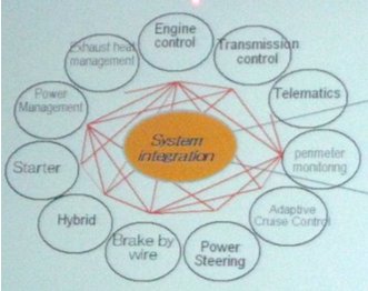
Ishi-san concluded that “Therefore Toyota needs to become an IT company”.
Toyota’s current development process: Waterfall
Imagine our surprise when he pulled up this picture:
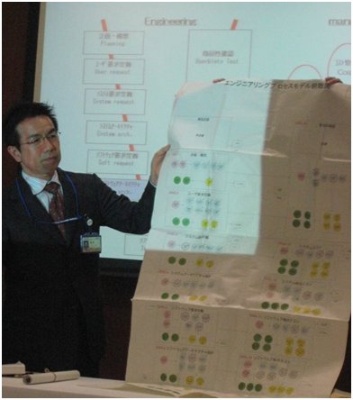
It was all there. The big V. Architects that don’t code. Distinct phases – all requirements to be complete and signed off before before coding, all code complete before testing, etc. He even called it a waterfall method.
We asked if he was happy with this way of developing. The answer was No. He told us about all kinds of problems they are having, most of them familiar to anyone that has experienced waterfall-style software development. There are countless case studies illustrating why the waterfall process just isn’t appropriate for software development. Even the original paper on the waterfall model in 1970 (” Managing the development of large software projects ” by Dr Winston Royce) says “the implementation described above is risky and invites failure ”.
Toyota is moving towards lean and agile software development
We asked Ishii-san if he had considered Agile software development . He was aware of Agile and liked the ideas, and said they will probably move in that direction. But they will do it in the Toyota Way – patiently and methodically, as Agile is not a goal in itself. I couldn’t agree stronger.
He said that “we are trying to learn how to apply TPS (= what we call Lean in the west) to software development”. Imagine the look on our faces. We came there to learn from what we thought would be the holy grail of lean software development, most of us were expecting to be dazzled and impressed.
He showed us this version of the Toyota house:
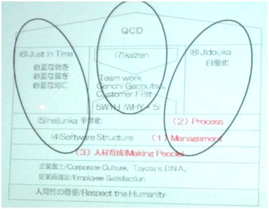
He said that they are currently at the bottom of the “house” (see the text highlighted in red, with numbers). Management, Process, and Making People. Without that, you can forget the other more technical aspects of lean such as Flow and Waste elimination.
He talked a lot about transparency – “How can you manage something that is invisible? How can we visualize software development? The key to success is mutual understanding between managers and engineers.”
He also talked a lot about engineer motivation and skills – that software is a creative process and motivation is key. “If engineers feel their own skills are improving by ‘visualization’, they can get high motivation for their work. The most important thing in the project is not only to develop software but also to cultivate engineers.”
One of the big impediments is their current software architecture. He didn’t get into details, but mentioned that they need to make significant changes in their architecture to enable Lean and Agile software development. My belief is that it is the other way around – that Lean and Agile software development provides a way to implement the architectural change in an iterative & incremental way.
He emphasized the importance of testing & fixing defects early. A defect found in the production phase is about 50 times more expensive than if it is found during prototyping. If the defect is found after production it will be about 1,000 – 10,000 times more expensive! I’ve seen other studies showing similar numbers. He showed some data on this, visualized in the bar chart below:
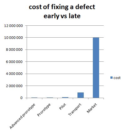
Reality turned out to be worse, a lot worse! As Toyota’s current problems with the Prius braking systems is costing them over $2 000 000 000 (2 billion!) to fix because of all the recalls and lost sales. “Toyota announced that a glitch with the software program that controls the vehicle’s anti-lock braking system was to blame".
Standardization and metrics – is Toyota going too far?
Most of Toyota’s ideas about how to do Lean software development resonated well with me. My feeling was that they are on the right track.
One thing bothered me though – the extreme focus on detailed metrics. I agree with the value of visualization, standardization, and data-driven process improvement – but only if used at a high level. My feeling was that Toyota was going to far. They say engineer motivation is critical, but how motivating is it to work in an organization that plans and measures everything you do – every line of code, every hour, every defect, how many minutes it takes to do an estimate, etc? I saw very thick and detailed process manuals about this – not only at Toyota, but at other Japanese companies that claimed to be implementing Lean software development.
The thought “ugh… micromanagement” popped into my head several times during the tour. Maybe it’s a cultural thing.
I’ve spent years helping IT companies implement this stuff in practice. I’ve found that in many cases both motivation and predictability improves when my clients decrease the level of detail in their estimate and plans. Software development seems inherently unpredictable, so spending too much time and effort trying to make detailed estimates and plans is wasteful and in some cases even counterproductive. Having detailed manuals for everything you do stifles innovation and creativity. Many of my peers and colleagues in the Agile software development community share this experience.
So my feeling is that either the Agile community has something to learn from Toyota, or Toyota has something to learn from the Agile community. Probably both.
Closing thoughts
It is deeply engrained in Toyota’s culture to be dissatisifed with the status quo. So my feeling is that even if they had a really good software development process, Ishii-san would have said that they were dissatisfied with it and wanted to improve it.
Despite all the problems Ishii-san mentioned, my first thought was that their process can’t be all bad since they are a successful company with millions of cars all around the world using their software. The Prius model was developed in record-short time despite the extreme level of innovation in that project.
I hadn’t (at that time) heard anything about quality problems with Toyota’s software. So waterfall or not, they still seemed to know what they were doing.
In fact, my conclusion after the trip was “well, now I know that there’s at least one company in the world that can succeed with the waterfall model” and I decided to stop bashing the waterfall model as hard as I usually do.
Now, however, with all the problems Toyota are having, I’m starting to reconsider. Are these problems software related? Could they have been avoided if Toyota used Lean & Agile software development instead of the waterfall model? I can’t sure, but I suspect yes.
Acknowledgements
Many people helped make this trip (and article) possible. I’m grateful to you all, and I’d especially like to thank:
- Satoshi Ishii-san and Toyota for finally telling the world how they do software development
- Mary and Tom Poppendieck for facilitating a Hansei (reflection) after each day on the tour. This helped us sort out our thoughts.
- Kenji Hiranabe for enabling the visit to Toyota.
- Bent Jensen and Best Brains for organizing the first Roots of Lean Study tour . They are doing it again, click here if you want to join !
The lean study tour was extremely inspiring and well-organized! I’ve lived in Japan for 16 years so I wasn’t sure I’d learn anything new – but going back there with ‘Lean glasses’ on I met so many interesting people and saw so many interesting things that I’ve realized my Lean journey has only just begun.
44 responses on “ Toyota’s journey from Waterfall to Lean software development ”
Hej Henrik, just wanted to thank you for an excellent write-up! I’ve never been to Japan myself, but would love to go there. See you! /Tobbe
Thank you for publishing this! It is excellently presented and extremely interesting.
I think it is great both that (a) Toyota was so willing to openly share their “warts and all” approach and aspirations with you, and (b) you wrote about it.
My father went on a similar study tour Japan in 1986 on a trip with Brian Joiner, Myron Tribus, and Peter Scholtes to meet with W. Edwards Deming and executives at many Japanese companies for a week and a half. Scholtes wrote an 18 page article about his impressions and lessons learned from the trip. It can be found here: http://cqpi.engr.wisc.edu/system/files/r005.pdf
While their trip focused primarily on manufacturing companies, it is still quite an interesting read. I’d recommend pages 7-8 in which W. Edwards Deming delivers a “scolding” lecture.
– Justin Hunter
Hi Henrik, I developed software a few years back at Toyota’s European headquarters in Brussels – and yep, pure waterfall there too. This was business process software and nothing to do with on-board car software and yet they still insisted on waterfall.
14 million lines of code on the Lexus eh? Seems a little on the extreme side to me. No wonder the Lexus range is so expensive!
Great post, it/s really interesting to see that toyota, were so much of lean thinking has come from is doing waterfall development.
who would/ve thought…
You talk about spontaneity and innovation, but maybe they just don’t need those in their embedded software at Toyota. Maybe getting tens of parts and systems that have to work together but each take time to build, out on time, takes planning. You can’t just ‘push back’ a car’s release date, or drop features. You surely aren’t going to try to fit all 1,000 engineers in the same Agile room and get them to ‘just talk’. I think this is a strong case for planning and waterfall; Agile isn’t a panacea.
Developing a next-gen car like the Prius takes A LOT of innovation. And the waterfall method was not working well for them. And there is no conflict between planning, innovation, and agile.
Great post Henrik. Thanks for sharing with the community. Why did it took you one year to write about this?
I wonder that myself :o) I think I had to get my thoughts sorted out. And I had other more immediate priorities competing for my time. Anyway glad to finally get this article out!
Thank you very much for this feedback. People : I would really like to know the Toyota context about people. In agile development, we talk a lot about the iterative/flow process, but people maturity is not our concern enough. Do you know if their software team are more stable than in the traditional western countries software industries? About Standardization and metrics : Having them all long a car product development is probably demotivating. Should we really have a pre-production with these metrics not correlated to the software innovation team production?
Ishii-san heavily emphasized the importance of the people aspect – the maturity and motivation of the people doing the development. I didn’t actually get to meet the teams and see their workspace though, that would have been interesting.
One of the big dysfunctions I have seen in large organizations is how poorly communication flows up the management hierarchy/chain of command, even in companies which are trying to do Lean. Did you get any feel for how well the information actually flowed at Toyota?
Cheers, Peter
Unfortunately not.
I’ve heard the estimate of tens of millions of lines of code in modern automobiles and that number has always seemed extremely high to me. I’ve also heard explanations that the “lines of code” in this case is more like assembly language instructions rather than a high-level language like Java or C#, which if true would make 14 million lines sound more reasonable. Can anyone with actual knowledge comment on that?
Ishii-san said that the 14 million lines of code for the Lexus LS460 include the navigation system (which I assume isn’t specific to that model)
Nice article. Waterfall or Lean? Pick the one that works for you. Clearly Toyota got it wrong this time and learned a valuable lesson. In my experience, the more you try to reduce the cost of software development, the more expensive it becomes in the end.
If that, “eliminating waste” can not be achieved? or “eliminating waste” activities won’t result in “cost saving” at all?
Hi Henrik, thanks for posting this. I always love your clarity and balanced approach. It is interesting to see how even the most prominent Lean enterprises haven’t yet realized how to pursue flow in software development.
As Lean-Agile software development matures and gains more and more visibility, the potential for cooperation and synergies will be greater than ever 😀
Hi Henrik, Thanks for sharing your experience. Micromanagement of tasks has its own disadvantages and biggest of them all is decreasing the motivation of developers. IMO, one should leave the deadlines to developers for them to mangage it and solely focus on the quality/testing of deliverables.
Seems pretty egotistical to think you’re going to teach Toyota how to implement TPS in software. I’d say you still have a lot to learn. As for Waterfall being a failure, how do you explain the thousands of banking systems, defense systems, telecommunications systems, etc that we rely on every day, all developed using waterfall?
Waterfall is useful for systems that Gartner describes as Systems of record (e.g. core banking system) with a life span of 10 or more years. While the agile approach is useful for solutions with shorter lifespan (speaking in Gartner terms: Systems of innovations or competitiveness).
Does this answer your question?
Great article! I completely agree with the product development comment; ‘A defect found in the production phase is about 50 times more expensive than if it is found during prototyping.’ Thanks for this.
I visited Toyota to learn, not teach. Ishii-san was the one saying that their current SW development process wasn’t working well, not me.
The fact that many companies use the waterfall method doesn’t mean it is good. On the contrary, there is an overwhelming amount of evidence of the high failure rate of waterfall projects, for example in the CHAOS reports from the Standish group.
Hi, There is no doubt that Waterfall model has delivered as there are living examples. Now the question is under what circumstances waterfall model fails? Waterfall model works perfectly IF, the solution requirements can be defined with absolute clarity. If development starts before the required level of clarity is available (learning happens during development) costly rework becomes imperative over and above throwing the carefully planned schedule to winds. Result will be utter chaos, cost escalation and project failure.
Agile approach allows changes during development. As there is no overall plan made, there is no chaos created due to change. However, there could be rework due to changes (fed back into the product backlog in SCRUM). Careful planning and sequencing of product back log to attain READY status is still important.
By the way, there is also at least one article questioning the reliability of CHAOS report published by Standish Group (Ref. The Rise and Fall of the Chaos Report Figures by J. Laurenz Eveleens and Chris Verhoef, Vrije Universiteit Amsterdam).
Cheers, -Sreekumar
I am glad to inform you of the publication of my new book about Toyota Production System. The book is titled “The truth about Toyota and TPS” and can be found at the following link: http://amzn.com/2917260025
Regards, E. Kobayashi.
Looks like a very interesting book!
Hey man, at first I would like to thank you for sharing what you’ve learned, that’s great. Second, I have to confess that I got a little bit disapointed now that I know that they are using waterfall over there. I really appreciate all the Toyota Way and Lean, I’m sure that their principles are very well defined and also really aligned and complementary to agile methods. They have a lot of empirical processes in their culture and when it comes to software their are using a deterministic approach? It makes me have feel that at some point they lost their relation with their own roots, and maybe the legacy that they left us is better than what they are currently doing and the last results that they showed us… What do you think about that?
Before making further conclusions people should realize some important things: 1) Embedded software is a different kind of animal than e.g. web sw. 2) Most of the software in Toyota cars is not made by Toyota company. 3) Automotive industry relies on supplier chains, having tier-1, tier-2 etc. suppliers rather than one company making all. 4) V-model is widely used in embedded software development. The right-hand side (test) can be done in parallel (or even before if you truly believe in test-first approach) so it does not need to be followed in waterfall way. 5) For most software, Toyota or some another brand company, is not involved in bottom part of V at all. 6) Supplier’s development method can be scrum, waterfall, spiral etc. model. 7) Unit costs is still the driving force for the automotive industry – and that fits poorly to software.
Thanks you for sharing this. I am impressed you can write it so vivid after nearly a year. Being there myself I find it a very accurate description of what we heard. I am though not so sure we can blame Toyotas current problems on not using agile/lean software development. Unfortunately they have much deeper problems that can not be solved by a quick transition to agile development. See for instance these two recent articles: http://bit.ly/b0THrW and http://bit.ly/dcfC65
Very interesting articles! Thanks for pointing them out.
I think this article is very interesting. However I disagree with some of your observations.
The V model does not necessarily translate to a waterfall model. It’s the length of the iterations that is the important – the feedback time based on the amount of “noise” in the process.
Or as Schwaber describes it:
“Scrum is based in empirical process control theory. As the degree of complexity rises, the number of inspections must be increased. Because of the increased frequency of inspections, the opportunity for adaptation also increases”
It does not matter if you have the V-model or not, it’s how often you verify the results that is important. Also, how much adaptation that is needed when developing a car will vary between the various components. In some cases you will have a very defined set of inputs and a defined set of outputs from that software (as in TDD). TDD is actually a way of strictly determining the requirements for a piece of software – but the verification is done according to the V-model.
And having third party suppliers, you need a process for agile development that supports procurement of agile development – which for example would exclude fixed price contracts.
In the (car) manufacturing industry, it is also much harder to ignore depenendencies, and you might have to introduce network diagrams to track or resolve them (which according to Schwaber is one of the major impediments to being agile) – but what is the alternative? Designing the cars iteratively? Including design, procurement and manufacturing?
The problem is that when it comes to cars, percieved quality includes grade. That is – quality is not only conformance to specification, but also “fitness for purpose”.
If I would make a process for software development for car manufacturers, I would not use a process like Scrum directly. I would look at the costs of change, the knowledge of changes (both what and how to change things), the dependencies (hardware, software and procurement), and then I would make a prioritization on the most important constraints (for example quality). Only then it is possible to say at what stages they should work iteratively – how long the iterations should be and how to manage and resolve dependencies.
Hi Klas! Thanks for your comment. I agree that the V model doesn’t always mean waterfall. But in this case it apparently did (Ishii-san even referred to it as a waterfall model at one point, if I remember correctly). The problems he described were also very typical waterfall symptoms (for example big test & fix cycle at end of project). Scrum or not, any suitably adapted combination of Agile methods (for example Scrum/XP/Kanban) would probably serve better than their current model.
Hi Henrik, this study is really interesting. I haven’t had the opportunity to go to the roots of Toyota but according to my studies, I suspect that Toyota uses a waterfall like development method due to their own product development culture.
AFAIK, they have a phase called Kentou which is the period at the beginning of the process of developing a product, where they develop studies and designs that will define in up-front what the final product will be. At the end of this phase they deliver a document called Sijisho, which means “document with direct commandment”. Once delivered, the Sijisho becomes law at Toyota. Since this is deeply rooted in their culture, and they must know how software components will interact with the other car’s components, they need to define things up-front. Nevertheless, I might be wrong.
I also don’t like their “micro management” style with so detailed metrics. I believe that there is a lot in the agile way that could really make improvements in the way they develop software, specially with respect to people.
I liked your experience and the more important is that you have shared this useful and important information with us. I greatly appreciate your post.
- Pingback: Jaguar recalls 17500 cars due to software glitch | Toyota Recall
Major thankies for the post. Much obliged.
- Pingback: Lean Software Development – my Experience | Lean Software Development
- Pingback: Why Driverless Cars? | Survival of the Craziest
- Pingback: defective thinking « diffidence
Good initiative, step to move ahead.
can someone provide 3 projects based on lean software development
Thanks for sharing!
Having third party suppliers, you need a process for agile development that supports procurement of agile development – which for example would exclude fixed price contracts.
13 years after still incredibely interesting, did Toyota filled the gap on the software side ?
Leave a Reply Cancel reply
Your email address will not be published. Required fields are marked *
Save my name, email, and website in this browser for the next time I comment.
This site uses Akismet to reduce spam. Learn how your comment data is processed .
- Software Engineering Tutorial
Software Development Life Cycle
- Waterfall Model
- Software Requirements
- Software Measurement and Metrics
- Software Design Process
- System configuration management
- Software Maintenance
- Software Development Tutorial
- Software Testing Tutorial
- Product Management Tutorial
- Project Management Tutorial
- Agile Methodology
- Selenium Basics
- Software Development | Introduction, SDLC, Roadmap, Courses
- What is Software Development?
- Software Development Life Cycle (SDLC)
- Software Development Models - SDLC Models
- Top Software Development Topics to prepare for Interview
- Software Developer (SDE) Interview/Placement Preparation Guide
Software Development Evolution & Trends
- Evolution of Software Development | History, Phases and Future Trends
- 10 Reasons Why Software Development is Important ?
- Top 12 Software Development Languages [2024]
- Latest Software Development Technology/Trends to look out for [2024]
- Most Popular Software Development Companies in India 2023-2024
- Software Development Process
- Software paradigm and Software Development Life Cycle (SDLC)
- Top 5 SDLC(Software Development Life Cycle ) Methodologies
- Bug Life Cycle in Software Development
- Software Development Process Step by Step Guide | Requirement, Plan, Design, Develop & Deploy
- Role of Verification and Validation (V&V) in SDLC
- Software Quality - Software Engineering
- Software Testing Life Cycle (STLC)
Software Development Models & Methodologies
- What is SDLC(Software Development Life Cycle) and its phases
- 5 Most Commonly used Software Development Methodologies
- Top 8 Software Development Life Cycle (SDLC) Models used in Industry
- Waterfall Model - Software Engineering
- What is Spiral Model in Software Engineering?
- Advantages and Disadvantages of using Spiral Model
- SDLC V-Model - Software Engineering
- Prototyping Model - Software Engineering
- Rapid application development model (RAD) - Software Engineering
- Agile Software Development - Software Engineering
- Waterfall vs Agile Development | Software Development Life Cycle Models
Agile Software Development
- Agile Software Development Methodology | Framework, Principles, and Benefits
- Agile Development Models - Software Engineering
- Agile Methodology Advantages and Disadvantages
- Agile SDLC (Software Development Life Cycle)
- User Stories in Agile Software Development
- Crystal methods in Agile Development/Framework
- Agile Software Testing
- Agile Software Process and its Principles
- What are the 4 Agile Values?
- What is Scrum in Software Development?
- Lean Software Development (LSD)
Software Developer Jobs
- Software Developer - Salary, Skills and Future Career
- Software Development Team: Designations & Structure
- 10 Crucial Team Roles in a Software Development Team
- Senior Software Engineer Job Description
- 7 Best Software Development Trends to Follow
Comparisons in Software Development
- Difference between Software Development, Web Development and App Development
- Difference between Traditional and Agile Software Development
- Competitive Programming vs Software Development - Where Should I Invest My Time?
- Difference between Full stack developer and Software developer
- Difference between Software Developer and Software Designer
- Difference between Agile and SDLC
Software Development Advanced Topics
- A Complete Overview of Android Software Development for Beginners
- What is Software Security - Definition and Best Practice?
- Introduction to Exploratory Style of Software Development
- How to Keep Your Skills Updated As a Software Developer?
- Characteristics of Adaptive Software Development
Waterfall Model – Software Engineering
The classical waterfall model is the basic software development life cycle model. It is very simple but idealistic. Earlier this model was very popular but nowadays it is not used. However, it is very important because all the other software development life cycle models are based on the classical waterfall model.
Table of Content
What is the SDLC Waterfall Model?
Features of the sdlc waterfall model, importance of sdlc waterfall model, phases of sdlc waterfall model – design, advantages of the sdlc waterfall model, disadvantages of the sdlc waterfall model.
- When to Use the Waterfall Model?
Applications of SDLC Waterfall Model
Frequently asked questions on waterfall model (sdlc) – faqs.
The waterfall model is a software development model used in the context of large, complex projects, typically in the field of information technology. It is characterized by a structured, sequential approach to project management and software development .
The waterfall model is useful in situations where the project requirements are well-defined and the project goals are clear. It is often used for large-scale projects with long timelines, where there is little room for error and the project stakeholders need to have a high level of confidence in the outcome.
- Sequential Approach : The waterfall model involves a sequential approach to software development, where each phase of the project is completed before moving on to the next one.
- Document-Driven: The waterfall model relies heavily on documentation to ensure that the project is well-defined and the project team is working towards a clear set of goals.
- Quality Control: The waterfall model places a high emphasis on quality control and testing at each phase of the project, to ensure that the final product meets the requirements and expectations of the stakeholders.
- Rigorous Planning : The waterfall model involves a rigorous planning process, where the project scope, timelines, and deliverables are carefully defined and monitored throughout the project lifecycle.
Overall, the waterfall model is used in situations where there is a need for a highly structured and systematic approach to software development. It can be effective in ensuring that large, complex projects are completed on time and within budget, with a high level of quality and customer satisfaction.
- Clarity and Simplicity: The linear form of the Waterfall Model offers a simple and unambiguous foundation for project development.
- Clearly Defined Phases: The Waterfall Model’s phases each have unique inputs and outputs, guaranteeing a planned development with obvious checkpoints.
- Documentation: A focus on thorough documentation helps with software comprehension, upkeep, and future growth.
- Stability in Requirements: Suitable for projects when the requirements are clear and steady, reducing modifications as the project progresses.
- Resource Optimization: It encourages effective task-focused work without continuously changing contexts by allocating resources according to project phases.
- Relevance for Small Projects: Economical for modest projects with simple specifications and minimal complexity.
The Waterfall Model is a classical software development methodology that was first introduced by Winston W. Royce in 1970. It is a linear and sequential approach to software development that consists of several phases that must be completed in a specific order.
The Waterfall Model has six phases which are:
1. Requirements: The first phase involves gathering requirements from stakeholders and analyzing them to understand the scope and objectives of the project.
2. Design: Once the requirements are understood, the design phase begins. This involves creating a detailed design document that outlines the software architecture, user interface, and system components.
3. Development: The Development phase include implementation involves coding the software based on the design specifications. This phase also includes unit testing to ensure that each component of the software is working as expected.
4. Testing: In the testing phase, the software is tested as a whole to ensure that it meets the requirements and is free from defects.
5. Deployment: Once the software has been tested and approved, it is deployed to the production environment.
6. Maintenance: The final phase of the Waterfall Model is maintenance, which involves fixing any issues that arise after the software has been deployed and ensuring that it continues to meet the requirements over time.
The classical waterfall model divides the life cycle into a set of phases. This model considers that one phase can be started after the completion of the previous phase. That is the output of one phase will be the input to the next phase. Thus the development process can be considered as a sequential flow in the waterfall. Here the phases do not overlap with each other. The different sequential phases of the classical waterfall model are shown in the below figure.
Waterfall Model-Software Engineering
Let us now learn about each of these phases in detail which include further phases.
1. Feasibility Study:
The main goal of this phase is to determine whether it would be financially and technically feasible to develop the software. The feasibility study involves understanding the problem and then determining the various possible strategies to solve the problem. These different identified solutions are analyzed based on their benefits and drawbacks, The best solution is chosen and all the other phases are carried out as per this solution strategy.
2. Requirements Analysis and Specification:
The requirement analysis and specification phase aims to understand the exact requirements of the customer and document them properly. This phase consists of two different activities.
- Requirement gathering and analysis: Firstly all the requirements regarding the software are gathered from the customer and then the gathered requirements are analyzed. The goal of the analysis part is to remove incompleteness (an incomplete requirement is one in which some parts of the actual requirements have been omitted) and inconsistencies (an inconsistent requirement is one in which some part of the requirement contradicts some other part).
- Requirement specification: These analyzed requirements are documented in a software requirement specification (SRS) document. SRS document serves as a contract between the development team and customers. Any future dispute between the customers and the developers can be settled by examining the SRS document.
The goal of this phase is to convert the requirements acquired in the SRS into a format that can be coded in a programming language. It includes high-level and detailed design as well as the overall software architecture. A Software Design Document is used to document all of this effort (SDD).
4. Coding and Unit Testing :
In the coding phase software design is translated into source code using any suitable programming language. Thus each designed module is coded. The unit testing phase aims to check whether each module is working properly or not.
5. Integration and System testing:
Integration of different modules is undertaken soon after they have been coded and unit tested. Integration of various modules is carried out incrementally over several steps. During each integration step, previously planned modules are added to the partially integrated system and the resultant system is tested. Finally, after all the modules have been successfully integrated and tested, the full working system is obtained and system testing is carried out on this. System testing consists of three different kinds of testing activities as described below.
- Alpha testing: Alpha testing is the system testing performed by the development team.
- Beta testing: Beta testing is the system testing performed by a friendly set of customers.
- Acceptance testing: After the software has been delivered, the customer performs acceptance testing to determine whether to accept the delivered software or reject it.
6. Maintenance:
Maintenance is the most important phase of a software life cycle. The effort spent on maintenance is 60% of the total effort spent to develop a full software. There are three types of maintenance.
- Corrective Maintenance: This type of maintenance is carried out to correct errors that were not discovered during the product development phase.
- Perfective Maintenance: This type of maintenance is carried out to enhance the functionalities of the system based on the customer’s request.
- Adaptive Maintenance: Adaptive maintenance is usually required for porting the software to work in a new environment such as working on a new computer platform or with a new operating system.
The classical waterfall model is an idealistic model for software development. It is very simple, so it can be considered the basis for other software development life cycle models. Below are some of the major advantages of this SDLC model.
- Easy to Understand: The Classical Waterfall Model is very simple and easy to understand.
- Individual Processing: Phases in the Classical Waterfall model are processed one at a time.
- Properly Defined: In the classical waterfall model, each stage in the model is clearly defined.
- Clear Milestones: The classical Waterfall model has very clear and well-understood milestones.
- Properly Documented: Processes, actions, and results are very well documented.
- Reinforces Good Habits: The Classical Waterfall Model reinforces good habits like define-before-design and design-before-code.
- Working: Classical Waterfall Model works well for smaller projects and projects where requirements are well understood.
The Classical Waterfall Model suffers from various shortcomings we can’t use it in real projects, but we use other software development lifecycle models which are based on the classical waterfall model. Below are some major drawbacks of this model.
- No Feedback Path: In the classical waterfall model evolution of software from one phase to another phase is like a waterfall. It assumes that no error is ever committed by developers during any phase. Therefore, it does not incorporate any mechanism for error correction.
- Difficult to accommodate Change Requests: This model assumes that all the customer requirements can be completely and correctly defined at the beginning of the project, but the customer’s requirements keep on changing with time. It is difficult to accommodate any change requests after the requirements specification phase is complete.
- No Overlapping of Phases: This model recommends that a new phase can start only after the completion of the previous phase. But in real projects, this can’t be maintained. To increase efficiency and reduce cost, phases may overlap.
- Limited Flexibility: The Waterfall Model is a rigid and linear approach to software development, which means that it is not well-suited for projects with changing or uncertain requirements. Once a phase has been completed, it is difficult to make changes or go back to a previous phase.
- Limited Stakeholder Involvement: The Waterfall Model is a structured and sequential approach, which means that stakeholders are typically involved in the early phases of the project (requirements gathering and analysis) but may not be involved in the later phases (implementation, testing, and deployment).
- Late Defect Detection: In the Waterfall Model, testing is typically done toward the end of the development process. This means that defects may not be discovered until late in the development process, which can be expensive and time-consuming to fix.
- Lengthy Development Cycle: The Waterfall Model can result in a lengthy development cycle, as each phase must be completed before moving on to the next. This can result in delays and increased costs if requirements change or new issues arise.
When to Use the SDLC Waterfall Model?
Here are some cases where the use of the Waterfall Model is best suited:
- Well-understood Requirements: Before beginning development, there are precise, reliable, and thoroughly documented requirements available.
- Very Little Changes Expected: During development, very little adjustments or expansions to the project’s scope are anticipated.
- Small to Medium-Sized Projects : Ideal for more manageable projects with a clear development path and little complexity.
- Predictable: Projects that are predictable, low-risk, and able to be addressed early in the development life cycle are those that have known, controllable risks.
- Regulatory Compliance is Critical: Circumstances in which paperwork is of utmost importance and stringent regulatory compliance is required.
- Client Prefers a Linear and Sequential Approach : This situation describes the client’s preference for a linear and sequential approach to project development.
- Limited Resources : Projects with limited resources can benefit from a set-up strategy, which enables targeted resource allocation.
The Waterfall approach involves little client engagement in the product development process. The product can only be shown to end consumers when it is ready.
- Large-scale Software Development Projects: The Waterfall Model is often used for large-scale software development projects, where a structured and sequential approach is necessary to ensure that the project is completed on time and within budget.
- Safety-Critical Systems: The Waterfall Model is often used in the development of safety-critical systems, such as aerospace or medical systems, where the consequences of errors or defects can be severe.
- Government and Defense Projects: The Waterfall Model is also commonly used in government and defense projects, where a rigorous and structured approach is necessary to ensure that the project meets all requirements and is delivered on time.
- Projects with well-defined Requirements: The Waterfall Model is best suited for projects with well-defined requirements, as the sequential nature of the model requires a clear understanding of the project objectives and scope.
- Projects with Stable Requirements: The Waterfall Model is also well-suited for projects with stable requirements, as the linear nature of the model does not allow for changes to be made once a phase has been completed.
For more, you can refer to the Uses of Waterfall Model .
The Waterfall Model has greatly influenced conventional software development processes. This methodical, sequential technique provides an easily understood and applied structured framework. Project teams have a clear roadmap due to the model’s methodical evolution through the phases of requirements, design, implementation, testing, deployment, and maintenance.
1. What is the difference between the Waterfall Model and Agile Model?
Ans: The main difference between the Waterfall Model and the Agile Model is that the Waterfall model relies on thorough front planning whereas the Agile model is more flexible as it takes these processes in repeating cycles.
2. What is the Waterfall Process?
Ans: The Waterfall process is a step-by-step development and project management process. As the name suggests, this model follows a straight path where each step (like planning, designing, building, testing, and launching) needs to be finished before moving to the next. This approach works well for projects where all the steps are clear from the beginning.
3. What are the benefits of the Waterfall Model?
Ans: The waterfall Model has several benefits as it helps projects keep a well-defined, predictable project under the budget.
4. Is Waterfall better than Agile?
Ans: Waterfall works best for well-defined, unchanging projects, while Agile is for dynamic, evolving projects. For more differences, refer – Waterfall vs Agile .
Related Articles:
For more Software Engineering Models, you can refer to:
- Iterative Model
- Agile Model
- Spiral Model
Please Login to comment...
Similar reads.
- Software Engineering
Improve your Coding Skills with Practice
What kind of Experience do you want to share?
Agile Methodology Vs. Traditional Waterfall SDLC: A case study on Quality Assurance process in Software Industry
Ieee account.
- Change Username/Password
- Update Address
Purchase Details
- Payment Options
- Order History
- View Purchased Documents
Profile Information
- Communications Preferences
- Profession and Education
- Technical Interests
- US & Canada: +1 800 678 4333
- Worldwide: +1 732 981 0060
- Contact & Support
- About IEEE Xplore
- Accessibility
- Terms of Use
- Nondiscrimination Policy
- Privacy & Opting Out of Cookies
A not-for-profit organization, IEEE is the world's largest technical professional organization dedicated to advancing technology for the benefit of humanity. © Copyright 2024 IEEE - All rights reserved. Use of this web site signifies your agreement to the terms and conditions.
A comprehensive approach to assess the seismic vulnerability of archaeological sites: the Wupatki Pueblo in Arizona
- Original Article
- Open access
- Published: 31 May 2024
Cite this article
You have full access to this open access article

- Laura Gambilongo ORCID: orcid.org/0000-0002-1897-7149 1 ,
- Nicola Chieffo 1 &
- Paulo B. Lourenço 1
The proposed research work presents a comprehensive approach to assessing the seismic vulnerability of archaeological sites. This approach aims to be a quick and easy-to-use investigation procedure that enables accurate and large-scale evaluations. While the methods employed are well-established in the literature and have been widely applied to buildings, this study contributes by proposing a structured framework that integrates different assessment procedures at different levels of analysis, specifically tailored to archaeological sites. The analysis is divided into three stages within the conceptual framework: (i) the application of the Masonry Quality Index; (ii) seismic vulnerability assessment and prediction of expected damage; and (iii) analysis of individual walls’ structural response through strength domain, capacity and fragility curves. Specifically, the study explores and adapts four Vulnerability Index methods, i.e. GNDT, Formisano, Vicente and Ferreira methods, to suit the specific characteristics of archaeological sites. To this end, a simplified procedure is proposed to estimate the conventional strength in the methods’ forms. The comparison of the index-based methods is then crucial for critically evaluating the reliability of vulnerability estimations. The paper illustrates the application of this framework through a detailed case study, i.e. the archaeological site of Wupatki Pueblo in Arizona (US), demonstrating its effectiveness in evaluating the seismic risk and defining the vulnerability distribution of the site. Consequently, this approach facilitates the identification of the most sensitive areas, which necessitate further investigation, providing useful outcomes for the decision-making process concerning the conservation and protection of archaeological sites.
Avoid common mistakes on your manuscript.
1 Introduction
Historic masonry structures constitute a significant portion of the world’s cultural heritage and, thus, present a multitude of challenges in analysis, diagnosis, conservation and rehabilitation (ICOMOS 2003 ). Due to their uniqueness and construction complexity, these constructions require careful consideration and specialised expertise to preserve and maintain their inestimable cultural, social and economic value. Historic masonry structures were built based on the knowledge and experience of builders, who over time developed best practices referred to as “rules of art” (Giuffrè 1993 , 1996 ). However, this traditional approach often resulted in randomly textured masonries, combined use of different materials and subsequent alterations to the original structure. The geometric complexity of these masonry structures, usually built to resist only gravitational loads, further contributes to their seismic vulnerability (Chieffo et al. 2023 ). In addition, their structural behaviour is affected by the decay of materials and the damaged state. Due to the difficulty of considering all the variables involved and the limited knowledge of construction and evolutionary characteristics, predicting the structural behaviour of historic masonry structures is challenging, especially under seismic actions.
Historic masonry structures encompass a vast majority of archaeological ruins, which are spread around the world and serve as tangible evidence of past human civilisations (Aguilar et al. 2015 ). Conserving these sites extends beyond safeguarding the structures themselves; it involves preserving their immense cultural and historical value (Lagomarsino and Podestà 2010 ). These remains are limited, unique, and non-renewable resources, making their conservation even more critical (De la Torre and Mac Lean 1997 ). Many of these structures have deteriorated over the years, losing structural integrity and suffering deterioration, leading to partial or total collapse (Albuerne and Williams 2017 ; Autiero et al. 2021 ; Ruggieri et al. 2018 ). As a result, ruins often exhibit isolated structural elements, such as arches, individual walls, columns etc., which are highly vulnerable. Archaeological sites face a variety of potential risks that compromise their preservation. Oftentimes, these sites remain buried for many centuries after their construction, and when unearthed, they become exposed to natural and human hazards, respectively. Natural events such as earthquakes, floods, landslides, fires, and others represent direct and acute risks whereas slowly developing issues such as water infiltration, soil settlement, and anomalous stresses in the structure gradually compromise the site's long-term stability (Marino 2019 ). However, vulnerability also depends on non-structural phenomena, which may involve the archaeological site as a whole (landscapes, decorations, etc.). Tourism growth and the subsequent development of facilities lead to increased pressure on the fragile historical remains. For instance, willingness to attract tourists often results in the reconstruction of architectural elements and structures, which can compromise the authenticity of the site. In addition, insufficient human and financial resources further hamper proper preservation efforts, especially when dealing with the heritage of a cultural minority (De la Torre and Mac Lean 1997 ). Thus, all these sources of damage make the vulnerability assessment of the archaeological ruins a complex problem, requiring analytical (cognitive and diagnostic) and design activities (Formisano et al. 2018 ; Di Lorenzo et al. 2019 ) within a systematic and long-term plan of maintenance (Cecchi and Gasparoli 2010 ; De la Torre and Mac Lean 1997 ).
In particular, with a special focus on structural behaviour, seismic hazard poses a significant threat to archaeological sites, as even low-intensity events can cause extensive damage. This is mainly due to the high seismic vulnerability of archaeological remains, i.e. their susceptibility to damage or collapse during an earthquake. The latter mainly occur due to the absence of global structural integrity and the absence of connections between structural elements, which generally lead to shear cracking and disintegration (Roca et al. 2019 ) and out-of-plane failure. Vulnerability is a critical parameter when determining the seismic risk of a site, along with exposure, i.e. its intrinsic value, and seismic hazard. Given the challenging nature of controlling seismic hazards and exposure, it is important to investigate a site's vulnerability for potential mitigation measures. The Italian Directive P.C.M ( 2007 ) proposes simplified models for conducting territorial-scale analyses of cultural heritage. However, these models are primarily intended for assessing the seismic vulnerability of archaeological assets that still exhibit global structural behaviour. Conversely, when dealing with masonry fragments lacking structural integrity, Podestà has introduced a more suitable methodology for defining limit domains. Once the hazard is known, this methodology specifies the geometric characteristics that macro-elements must possess to be considered safe (Podestà 2010 ). To date, several methodologies have also been proposed for seismic vulnerability assessment, commonly developed for buildings. In general, three main categories are identified: (i) empirical or statistical methods, (ii) analytical methods and (iii) hybrid methods, resulting from a combination of the other two (Shabani et al. 2021 ). Empirical methods rely on statistical data from observed damage in past earthquakes or expert judgement. They are commonly used for rapid assessments performed on an urban scale since geometric surveys and on-site inspections are sufficient to provide the necessary (Ferreira et al. 2017 ; Basaglia et al. 2018 ; Chieffo et al. 2022 , 2019 ; Chieffo and Formisano 2019 ). Screening (ATC 1989 ), Vulnerability Index methods (Benedetti and Petrini 1984 ; GNDT 1993 ; Vicente 2008 ; Formisano et al. 2010 ), and Damage Probability Matrices (Whitman and Reed 1973 ) fall into this category. These approaches can be also combined with the Macroseismic method, developed by Lagomarsino and Giovinazzi ( 2006 ), to evaluate the expected damage scenarios (Maio et al. 2015 ; Biglari and Formisano 2020 ). In contrast, analytical methods provide a more precise seismic assessment, as they use vulnerability curves derived from numerical analyses based on detailed or simplified models. Specifically, detailed analytical methods consist of nonlinear analyses that require sophisticated numerical simulations. Simplified analytical analyses, on the other hand, include collapse mechanism-based, capacity spectrum-based methods and fully displacement-based methods (Shabani et al. 2021 ). Besides a few attempts on the global-aggregate scale through automated procedures (Leggieri et al. 2022 , 2023 ), analytical methods, both detailed and simplified, are commonly adopted for seismic assessment on a local scale. This is because of the computational effort required, a large number of variables and the uncertainties involved. Although limited, there have been a few attempts at using analytical methods for the seismic assessment of archaeological sites. In Aguilar et al. ( 2015 ), Ruggieri et al. ( 2018 ) and Lorenzoni et al. ( 2019 ), Finite Element (FE) models were used for both global non-linear static (push-over) analysis and local kinematic limit analysis. Lourenço et al. ( 2012 ) also employed an FE model to conduct push-over and time history analyses, while Chácara et al. ( 2014 ) conducted a global linear static analysis and a local pushover analysis. Complementarily, Galassi et al. ( 2020a , b ) and Sassu et al. ( 2013 ) used rigid-block models. It is important to note that numerical models require an accurate calibration of the actual conditions of the structure, which can be achieved through on-site non-destructive testing. For instance, Marques et al. ( 2014 ) utilised ambient vibration tests to calibrate FEM models, and their outcomes were subsequently validated through kinematic limit analysis. Furthermore, understanding the structural performance of archaeological sites is particularly challenging due to difficulties in defining the geometry, materials, and level of damage. To address this, Di Miceli et al. ( 2017 ) proposed determining unknown parameters in probabilistic terms. Nevertheless, the presence of numerous uncertainties still implies that developing reliable models may be problematic. Furthermore, several authors (Ruggieri et al. 2018 ; Galassi et al. 2020a , b ) have recommended validating these models by different numerical methods (Galassi et al. 2022 ; Seçkin and Sayin 2022 ). Due to the time and effort required, this approach may not always be feasible, particularly for extensive sites. Recognizing the inherent lack of structural continuity in most archaeological sites, it becomes evident that conducting local analyses is imperative to ascertain necessary preventive interventions (Podestà 2010 ). Nonetheless, in line with the Italian Directive P.C.M ( 2007 ), a large-scale seismic assessment is an essential preliminary measure aimed at identifying the most vulnerable parts warranting further local studies (Lagomarsino and Podestà 2010 ). Empirical methods, such as Vulnerability Index methods, may be suited to this purpose, however, their effectiveness for seismic evaluation of archaeological sites has not yet been studied in the literature.
Based on the above considerations, the present work proposes a simplified approach for assessing the seismic vulnerability of archaeological sites. The suggested evaluation approach seeks to be a straightforward and quick tool, relying exclusively on data gathered through the geometry survey and on-site examination. While the methods utilised are well-established in the literature and have been widely applied to buildings, the contribution of this study lies in proposing a structured framework that integrates different assessment methods at different levels of analysis to evaluate archaeological contexts. To this end, the use of index-based procedures is herein explored for the first time by comparing and adapting them to the unique characteristics of archaeological sites. The methodology suggested was applied at the Wupatki Pueblo archaeological site, in Arizona (US), as part of the Integrated Site Conservation and Management Plan and Training for Wupatki National Monument, Arizona project, supported by the J. Paul Getty Trust.
This paper contextualises the case study and provides an overview of its main architectural and historical features. This is followed by a detailed description of the methodological approach, divided into three levels of analysis: (i) application of the Masonry Quality Index to selected walls, (ii) seismic vulnerability assessment and expected damage estimation of the site, and (iii) analysis of individual wall structural response. Accordingly, the outcomes of the case study application are presented and discussed. Finally, the main conclusions of the work are drawn and potential areas for future research and development are outlined.
2 The case study
Wupatki Pueblo is one of the largest and most impressive prehistoric ruins in the American Southwest. It was occupied by Ancestral Puebloans, also known as the Sinagua people, between 1100 and 1250 AD. The site is located within the Wupatki National Monument (WUPA), which covers over 140 km 2 of diverse landscapes and more than 2500 cultural sites. Located approximately 56 km northeast of Flagstaff (Coconino County, Arizona), Wupatki Pueblo is an open-air archaeological site that sits at an altitude of about 1480 m in the Wupatki Basin. The basin extends for about 130 km 2 along the East side of the East Kaibab Monocline and is bound to the southwest by the northeast edge of the San Francisco Volcanic Field. To the northeast, the basin descends to the Little Colorado River, which flows across the WUPA and demarcates its eastern boundary (Fig. 1 ).

Location of the Wupatki Pueblo
Hundreds of earthquakes were recorded in the Coconino County area between 1830 and 2011, most of them of magnitude, M w , less than or equal to 3.0. A few earthquakes were of medium magnitude (3.0 ≤ M w ≤ 5.0), and only three had a magnitude of 6.0 or higher (Anderson et al. 2021 ). While these earthquakes were typically not felt by residents and rarely caused damage, it is important to keep in consideration the potential seismic hazard of the area to ensure the structural integrity of the site. Still, considering historical seismicity, the probability of a catastrophic earthquake in the area is low as described in the study proposed by Anderson et al. ( 2021 ). Specifically, according to the Unified Hazard Tool provided by USGS (Unified Hazard Tool 2023 ), the site area is characterised by a Peak Ground Acceleration (PGA) of 0.16 g and 0.05 g with a probability of exceeding 2% and 10%, respectively, in 50 years.
2.1 Description of the site
Wupatki Pueblo was built on a narrow sandstone ridge that extends in a north–south direction. It comprises two main compact room blocks, known as the South and North Pueblos or Units, which are together referred to as the Main Pueblo. The site also includes a Ballcourt in the vicinity of the Main Pueblo, and a Community Room, also known as the Amphitheatre, located at the east of the North Unit (Fig. 2 ). While the room units are now two separate entities, they were most likely connected in the past (Brennan and Downum 2001 ). Both blocks are characterised by intersecting rock formations that cut through many of the rooms, some of which were built partially or entirely on boulders. Since the site is in ruins, this study focuses on the areas with relevant parts of the structure remaining. Specifically, the upper part of the South Pueblo has been considered as a structural aggregate (SA) consisting of 12 structural units (SUs), while the SA of the North Pueblo consists of 4 relevant SUs, as shown in Fig. 3 .

Overview of the Wupatki Pueblo archaeological site, view to the west

Satellite view of the Wupatki Pueblo indicating the area evaluated and the location of sonic tests
The complex was originally constructed with irregularly shaped Moenkopi sandstone blocks and earth-based mortar joints (Fig. 4 a). However, cement mortar was used during the reconstruction period, and over time the joints have been repointed with stabilised earth-based mortars. Although precise information on the cross-sections of the walls is lacking, observations of collapsed sections indicate that they consist of a double leaf with a few stones passing through the entire thickness (Fig. 4 b). Generally, there is no evidence of corner connecting elements, such as quoins, between orthogonal walls. The walls were built directly on the soil or boulders without a visible foundation (Fig. 4 c). Horizontal elements at floors and roofs are no longer present, but evidence of past timber beams remains, including a pair of beams and sockets in the walls where beams were hosted.

Material and building techniques: a Moenkopi sandstone blocks and earth-based mortar joints; b wall cross-section; c orthogonal walls and boulder intersection
The Wupatki Pueblo, mostly unearthed after centuries, is now alarmingly exposed to weathering, as it experiences hot, wet summers and approximately 100 days of below-zero temperatures during winter. Issues like water drainage, water and snow accumulation, freeze–thaw cycles due to temperature fluctuations and salt crystallisation cause deterioration in both the masonry walls and boulders, weakening the mechanical properties of the materials and damaging the structural integrity of the walls. Furthermore, recent extreme weather events, like heavy rainfalls, and the expected climate change further compound challenges in preserving the site.
2.2 Historical background
The Sinagua people were drawn to the area due to its natural resources. The surrounding landscape indeed provided the Ancestral Puebloans with water, fertile land for agriculture, and a variety of natural resources such as wood, clay, and stone. During its heyday between AD 1150 and 1250, the complex served as the largest and most influential pueblo in the WUPA region, acting as a hub for trade and exchange between neighbouring communities. The site supposedly consisted of over 100 rooms and housed about 100 people.
Today, Wupatki Pueblo is part of the Wupatki National Monument, which was established in 1924 by the National Park Service (NPS) to preserve the site and other cultural and natural resources in the area. However, early excavations in the 1930s and subsequent ones in the 1940s to 1960s were conducted arbitrarily and without proper documentation. Moreover, conservation efforts involved demolishing and reconstructing parts of the site to attempt to restore its original appearance (Brennan and Downum 2001 ).
In recent decades, the NPS has taken a more cautious approach to conservation efforts, to preserve the original features of the site. However, the lack of detailed reports makes it challenging to distinguish between original features and more recent interventions. Still, the most obvious reconstructions and invasive interventions have been removed.
2.3 In-situ non-destructive testing
As part of the project, several investigations and diagnostic activities were carried out to better understand the structural performance of the site. Non-destructive testing (NDT) was an important component, given the unique nature of the masonry and the wide range of materials used in its construction. Specifically, sonic tests were performed on six selected walls, as indicated in Fig. 3 . The sample size was constrained by the time available for the inspection and site accessibility. Nevertheless, the number of tests conducted was deemed adequate to estimate the mechanical properties of the masonry that, despite its peculiarity, apparently exhibited consistent characteristics across the entire archaeological site. The sonic pulse velocity test is a non-destructive method that employs elastic waves in the sonic range (20–20000 Hz) to evaluate the properties of a structural element (Miranda et al. 2013 ). Indeed, the analysis of the wave velocities enables qualitative characterization of the element, encompassing its consistency, homogeneity and deterioration. Additionally, the velocities of propagating waves can be correlated with the mechanical properties of the material (ASTM 2000 ). To make a quantitative assessment, the medium is assumed as elastic, isotropic, homogeneous and non-dispersive. Under this assumption, the mechanical P-wave velocity \({V}_{P}\) can be related to the material's dynamic elastic modulus \(E\) , Poisson’s ratio ν and density ρ through:
Then, the dynamic elastic modulus \(E\) of the masonry can be obtained from the wave velocity \(V_{P}\) , assuming a density of 2000 kg/m 3 and a Poisson’s ratio ν of 0.2. Six walls were investigated using both direct and indirect sonic pulse velocity tests, depending on the accessibility of the walls’ sides. Tests were conducted using an instrumented impact hammer (PCB Model 086D05) and an accelerometer (PCB model 352B) with a measurement range of ± 5 g and 1000 mV/g sensitivity. The adopted Data Acquisition System (NI model USB-4431) allows for a high sampling rate of up to 100 kHz, which is necessary for such tests. All tests were exclusively conducted on the stones within an approximately one-square-meter area by striking them. However, due to the irregularity of the masonry, it was not possible to define a regular grid with a constant distance between the points. Consequently, for each acquisition point, measurements were repeated to achieve at least five records that were then averaged. The results are summarised in Table 1 , with an average dynamic \(E\) of 1538 MPa. It is noteworthy that significant variations in velocity results were observed between direct and indirect tests. Indeed, direct tests produced higher values, sometimes comparable to the velocity in the stones, probably due to the presence of larger blocks and fewer mortar joints across the wall thickness. Additionally, the masonry’s compressive strength \({f}_{m}\) was estimated by dividing the dynamic elastic modulus \(E\) by a value equal to 550, as derived for the masonry from NTC ( 2018 ), with an average of 2.8 MPa. This indicates a reasonable quality of the masonry.
3 Multi-level methodological approach
The purpose of this section is to provide a detailed description of the methodology herein developed for a rapid seismic vulnerability assessment of archaeological sites. The methodological approach comprises an easy-to-use structured framework that combines well-established building-assessment methods adapted to evaluate archaeological sites. The workflow, depicted in Fig. 5 , is structured into three main tasks as follows:
Masonry characterisation using the Masonry Quality Index (MQI) method—The method is applied to selected walls to estimate the shear strength τ 0 and minimise uncertainties in determining the Conventional strength parameter within vulnerability index forms. It is important to analyse an adequate number of walls to ensure the findings accurately represent the actual masonry properties. As the method can be applied to any type of masonry walls without any modification or adaptation to the specific characteristics of the site, the authors believe there is no need to compare results with similar methods. Nevertheless, it is advisable to validate MQI results by comparing them with NDT findings, whenever available. If MQI and NDT results align, the reliability of the MQI is confirmed and the shear strength derived from the index can be used. Conversely, it is left to the operator’s discretion to determine which method they consider more reliable. Factors such as the number and techniques of the on-site tests should be carefully considered in this evaluation. It is worth noting that the methodological approach can be applied effectively regardless of the availability of such experimental data. In such cases, a comparison can still be made between the shear strength derived from the MQI and values found in the literature.
Seismic vulnerability assessment—Four different Vulnerability Index methods, namely GNDT, Formisano, Vicente and Ferreira methods, are applied to the site under investigation. Each method is to be accomplished in three steps: (i) selection of the form parameters that can be evaluated for the specific archaeological site; (ii) estimation of the conventional strength parameter using the simplified formulation herein proposed; (iii) calculation of the vulnerability index. Finally, these methods are compared to critically analyse the reliability of vulnerability estimations. If there are disparities in the vulnerability indices, it is essential to identify the parameters responsible for such discrepancies and assess whether their incidence in the overall index calculation reflects the site’s actual characteristics. In the last phase, the expected damage is also estimated through damage vulnerability curves based on the calculated vulnerability indices.
Local analyses—The response of individual walls is evaluated using strength domain, capacity curves and fragility curves. It is recommended that walls in the most sensitive areas, according to the vulnerability distribution, are analysed.

Structured framework of the methodological approach
In the subsequent sections, each task is described more in detail, outlining its implementation for the specific case study.
3.1 Masonry quality index
The quality of a masonry wall depends on both its constituents and the execution. The “rules of art” are a set of construction rules that ensure the wall’s compactness and monolithic behaviour. The mechanical properties and the structural response of walls are strongly influenced by the masonry’s quality. Indeed, irregular and low-quality masonries that lack monolithic behaviour (Vintzileou et al. 2015 ) exhibit a higher seismic vulnerability, as the collapse mechanism during seismic events often occurs due to disaggregation and leaf separation (Borri et al. 2020 ). This type of failure anticipates local and global mechanisms (Borri et al. 2015 ) and typically occurs at lower seismic intensities (De Felice et al. 2022 ). The Masonry Quality Index (MQI) method uses a visual survey and analysis of seven parameters related to structural behaviour to define a numerical index of masonry quality (Borri et al. 2015 ). The parameters are the following: mechanical characteristics and quality of masonry units (SM), dimensions of the masonry units (SD), the shape of the masonry units (SS), level of connection between adjacent wall leaves (WC), horizontal of mortar bed joints (HJ), staggering of vertical mortar joints (VJ), and quality of the mortar/interaction between masonry units (MM). Based on engineering judgement, each parameter is classified into three possible outcomes, i.e. fulfilled (F), partially fulfilled (PF) and not fulfilled (NF), and is associated with a numerical value according to the degree of fulfilment. The MQI is therefore calculated as the sum of these seven values according to Eq. ( 2 ):
The index ranges from 0 to 10, where a lower index value corresponds to a lower masonry quality. Additionally, the method accounts for different structural responses according to loading conditions, i.e. vertical, horizontal in-plane and horizontal out-of-plane loads. These conditions are reflected in three different indices, e.g. MQI V , MQI I and MQI O , respectively. Based on the index value, the masonry category can be therefore defined as A, good behaviour, B, average quality behaviour, and C, inadequate behaviour for each of the loading conditions (Borri et al. 2015 ).
The above-introduced method was applied to six walls of the case study, which had been investigated by sonic testing. It is important to note that the WC parameter was established using a qualitative approach as access to the cross-section of the examined walls was feasible, whereas the VJ parameter was determined quantitatively. Furthermore, the MM parameter was defined based on the results of non-destructive testing, including penetrometer, Schmidt hammer and pendulum hammer tests, performed on the earth-based mortars to estimate the mechanical properties. The results show that none of the walls falls into category A, i.e., good behaviour, under any loading condition. Specifically, five masonry panels exhibit average quality behaviour under vertical load, while under horizontal in-plane loading, only four walls still fall into the same category. All the examined walls are classified as inadequate under horizontal out-of-plane loading.
Applying the equations proposed by Borri et al. ( 2020 ) to relate the masonry quality index to the masonry mechanical properties, a range of values was calculated for compressive strength f m , Young’s modulus E and shear strength τ , as reported in Table 2 . To further check whether the MQI method is appropriate for the present study, a comparison is proposed between the average Young’s modulus E and compressive strength f m values obtained from the MQI method and sonic tests. It is important to acknowledge that there is a difference between the static ( E s t ) and dynamic ( E d y ) modulus of elasticity of stones (Vasconcelos 2005 ). The dynamic Young’s moduli from the sonic tests were therefore corrected into static values using the equation proposed by Makoond et al. ( 2020 ):
For comparison purposes, accordingly the masonry’s compressive strength \({f}_{m}\) was derived from the static modulus E s t by dividing it by 550 (NTC 2018 ).
Figure 6 shows the comparison of Young’s modulus and compressive strength values derived from both the index and the experimental data. For the majority of the walls analysed, fair consistency was found between the two sets of properties, with a similar average Young’s modulus and a difference in compressive strength of about 20%. Nevertheless, a notable difference was noted in walls 1, 2 and 6, which is likely attributed to the irregularity of the masonry. Also, it is important to consider that although the masonry construction technique appears to be consistent across the site, there is a lack of information concerning the majority of the cross-sections. Consequently, this could have a significant impact on the results of the sonic tests, especially in cases where walls were improperly restored or rebuilt. As stated in De Santis ( 2022 ), the comparison provides further confirmation of the index’s reliability in evaluating the in-plane and out-of-plane behaviour of the walls in the specific case study. Moreover, the validation of the MQI method legitimises the use of the shear strength τ, equal to 52 KN/m 2 , estimated according to the index and averaged across all the wall panels analysed, in the calculation of the conventional strength parameter of the Vulnerability Index methods, as described in the following sections. It is worth noting that the shear strength τ estimated via the MQI method is higher than the value recommended for this type of masonry in the Italian NTC 18 Code ( 2018 ), which is equal to 36 KN/m 2 (the second knowledge level and a confidence factor of 1.2 are considered). Nevertheless, the authors contend that this variation is acceptable, given that the MQI method accounts for a more comprehensive set of parameters in its estimation.

Comparison between MQI and sonic test results: a Young’s modulus E [MPa]; b compressive strength f m [MPa]
3.2 Seismic vulnerability assessment
Seismic vulnerability analyses aim to assess the level of damage that a generic structure may suffer under a seismic event of a certain intensity measure. It is therefore a fundamental and preliminary phase in conservation processes to evaluate the need for strengthening interventions.
As mentioned, simplified models for assessing the seismic vulnerability of archaeological sites on a territorial scale have been proposed in the Italian Directive P.C.M ( 2007 ) and by Podestà ( 2010 ). Nevertheless, this study examines the applicability and reliability of empirical methods, proposed in the literature for buildings, when applied to archaeological sites. Among empirical methodologies, the Vulnerability Index methods have been widely used for assessing the expected vulnerability of structural units, SUs, and structural aggregates, Sas, in historical centres (Chieffo et al. 2023 ). These methods consist of determining a vulnerability indicator through the evaluation of typological, structural and material parameters, both qualitative and quantitative, which characterise the seismic structural response of the unit. Each parameter is assessed individually according to four classes of increasing vulnerability (from A-lowest to D-highest), to which class scores \({S}_{i}\) are assigned. The influence of each parameter is then determined by multiplying \({S}_{i}\) by a weight factor \({W}_{i}\) , which depends on the relative importance of the parameter in the calculation of the global vulnerability. Thus, the vulnerability index I v is expressed as the weighted sum of the parameters:
The methodology was first proposed by Benedetti and Petrini ( 1984 ) and consisted of a ten-parameter survey form for the estimation of the vulnerability of masonry buildings in isolated conditions, i.e. not interacting with adjacent units. The approach involved expert judgments to assign weights and scores based on damage survey data. The Gruppo Nazionale per la Difesa dai Terremoti (GNDT) then developed and calibrated the original approach, proposing new survey forms based on eleven evaluation parameters (GNDT 1993 ). Later on, the original formulation (Benedetti and Petrini 1984 ) was extended to masonry building blocks in Vicente ( 2008 ) and Formisano et al. ( 2010 ), introducing 4 and 5 parameters, respectively, to account for mutual interaction among SUs in the same aggregate. These approaches provided important progress in the vulnerability assessment of buildings within aggregates, as the interaction effects with adjacent buildings significantly affect the seismic behaviour of the unit analysed. Furthermore, the calibration of class scores and weights was improved by Formisano et al. ( 2014 ) through the use of parametric analyses based on numerical models. While the aforementioned methods consider the single SU either isolated or within a SA, the Vulnerability Index method proposed by Ferreira et al. ( 2012 ) assesses the SA as a whole. The vulnerability assessment is therefore conducted at an urban scale through five evaluation parameters referred to the aggregate, dealing with geometrical irregularities, typology differences and interaction issues among buildings (Ferreira et al. 2012 ).
In general, the vulnerability assessment method should be set by the purpose of the analysis as well as the typological and structural characteristics of the units or aggregates being evaluated (Ferreira et al. 2013 ). As already stated, the application to archaeological sites is rather limited in the literature, so it seems appropriate to propose a comparative analysis between the mentioned methods. The comparison aims at determining the most reliable above-introduced methods to assess the vulnerability of the ruins, as well as to better address the uncertainties involved. The characteristics of archaeological sites differ from those of buildings in historic centres on which the Vulnerability Index methods have been developed. A first attempt to adapt these methods to archaeological sites is herein presented.
The form of each method was therefore revised by discarding the parameters that do not apply to the specific case study. For instance, the parameter accounting for the quality of floors could not be assessed since floors no longer exist. The selection of the evaluation parameters for each applied method is listed in Tables 3 , 4 , 5 , and 6 . For details on both the selected and discarded parameters, please consult the original forms in GNDT ( 1993 ), Vicente ( 2008 ), Formisano et al. ( 2010 ) and Ferreira et al. ( 2012 ). As a result, new maximum vulnerability values were determined by summing the individual parameters, which were deemed applicable to the specific case study. Furthermore, assuming that the walls of each SU behave as independent panels due to poor connections, a simplified method for estimating the conventional strength parameter is proposed, as detailed in the following paragraph.
3.2.1 The conventional strength parameter
The conventional strength parameter, also referred to as the distribution of plan resisting elements , accounts for the strength of the masonry SU against horizontal actions. The vulnerability class is determined based on the factor \(\alpha =C/\overline{C }\) , where \(C\) is intended as the ratio between the ultimate shear strength \({T}_{k}\) at the base of the SU, derived from Turnšek and Cacovic’s formulation, and the unit’s weight P; while \(\overline{C }\) is assumed equal to 0.4 as proposed in the literature (GNDT 1993 ). Denoting as \({A}_{t}\) the total in-plan area of the walls, \(A\) and \(B\) represents the minimum and maximum values between \({A}_{x}\) and \({A}_{y}\) (i.e. the areas of resisting elements in the orthogonal directions). Moreover \({a}_{0}\) and \(\gamma\) parameter indicates the surface ratios \(A/{A}_{t}\) and \(B/A\) , respectively. However, according to Benedetti and Petrini ( 1984 ), the following equation was adopted for the estimation of the above-introduced C parameter:
where \({\tau }_{k}\) is the characteristic shear strength of the wall, \(N\) is the number of floors and \(q\) is the average weight per unit of the total area of the floor. The parameter \(q\) is calculated as a function of the average specific weight of the masonry \({p}_{m}\) , the average floor height \(h\) and the average weight per unit area of the floor \({p}_{s}\) , as shown in Eq. ( 6 ):
The reliability of Benedetti’s formulation is limited to the assumption of global box-like behaviour. Archaeological sites are usually characterised by primitive construction and ruinous systems that do not guarantee a box-like behaviour. Adjacent walls are often poorly or not connected, and there are no headers between wall leaves. Furthermore, due to the conservation state of ruins, the walls are often totally or partially collapsed, thus with varying heights, and floors no longer exist. Therefore, a new formulation for the estimation of parameter C is proposed to assess the strength of masonry SUs under horizontal actions in archaeological sites. This formulation assumes that the unit’s walls behave as independent panels. Given the definition of C, assumed as the ratio between the ultimate shear strength \({T}_{k}\) concerning the verification level and the weight above \(P\) , \({T}_{k}\) can be estimated through Turnšek and Cacovic’s formula:
where \({A}_{T(\text{sec})}\) is the total cross-section area of the resisting elements, given by the sum of \({A}_{x}\) and \({A}_{y}\) (Fig. 7 ); \({\tau }_{k}\) is the characteristic tangential strength that can be deduced either from the prescriptions in Table C8.5.1 of the NTC 18 Code ( 2018 ) or, as stated in Sect. 3.1 , as a function of the MQI according to the equations proposed in Borri et al. ( 2020 ); and finally, \({\sigma }_{0}\) is the mean compressive stress among the corresponding compressive stress values achieved in the orthogonal directions, \({\sigma }_{0x}\) and \({\sigma }_{0y}\) . The compressive normal stress in the i-th direction \({\sigma }_{0i}\) is then evaluated as the ratio between the axial stress \({N}_{i}\) and the resistant area, \({A}_{i}\) , of the masonry wall section, given by:

Schematisation of a typical structural unit
In the absence of floors, \({N}_{i}\) is only equal to the dead loads of the masonry \({P}_{i}\) in the i -th direction, calculated as:
where \({p}_{m}\) is the specific weight of the masonry; \({h}_{av. k,i}\) is the height of the k -th wall in the considered direction, taken as the mean value in the case of irregular walls; \({L}_{k,i}\) and \({t}_{k,i}\) are the length and thickness of the walls, respectively (Fig. 7 ). The dead load \(P\) of the SU is then given by the sum of the dead loads of the walls in both orthogonal directions:
Therefore, it is proposed to estimate the C-factor according to Eq. ( 11 ), in which the factor \({a}_{0}=A/{A}_{t}\) is introduced to consider the percentage of resisting walls:
The above-introduced formulation was applied to evaluate the conventional strength parameter in the GNDT, Formisano and Vicente forms for the seismic vulnerability assessment of the Wupatki Pueblo. The results were compared with those obtained from the formulation found in the literature (Benedetti and Petrini 1984 ). As shown in Fig. 8 , due to higher values of \(\alpha =C/\overline{C }\) , the latter significantly underestimates the vulnerability of the SU, all of which fall into class A. Instead, in an archaeological site such as the Wupatki Pueblo, the proposed formulation performs better in estimating the parameter, demonstrating a fair distribution of results and vulnerability classes that are more consistent with the observed reality.

Comparison between conventional strength parameter results from the literature formulation and the simplified one proposed by the authors
In addition, the C-factor was calculated considering two different values of the characteristic shear strength \({\tau }_{k}\) , derived from Table C8.5.I in the NTC 18 Code ( 2018 ) and the MQI method. The first evaluated value is equal to 36 kN/m 2 , obtained by dividing the average value of the \({\tau }_{k}\) range provided for the class “masonry with rough-hewn blocks, with leaves of uneven thickness” by a confidence factor, CF, equal to 1.2 assuming a knowledge level, KL, set to 2. On the other hand, the MQI method provided a characteristic shear strength \({\tau }_{k}\) equal to 52 kN/m 2 , suggesting a better masonry performance. However, despite the higher values of \({\tau }_{k}\) , the vulnerability class of most SUs remains unvaried, as shown in Fig. 8 .
Finally, correlation curves are proposed in Fig. 9 to graphically determine the C-factor as a function of \({\alpha }_{0}=A/{A}_{t}\) , given the characteristic shear strength \({\tau }_{k}\) of the masonry. The aim is to simplify the estimation of the conventional strength parameter, which is one of the most time-consuming parameters of the vulnerability forms, and to extend the assessment to all archaeological sites close to the case study. It is important to mention that the curves developed are applicable for “masonry with rough-hewn blocks, with leaves of uneven thickness”, namely with an average specific weight of 20 kN/m 3 . Table 7 presents the angular coefficients of the correlation curves for varying \({\tau }_{k}\) , along with the standard deviation \(\sigma\) that should be taken into account within the range of variation.

The evaluation of the C-factor: a correlation curves assuming τ k in KN m −2 ; b variation range with a standard deviation \(\sigma\) of ± 0.03
3.2.2 Vulnerability index calculation
The archaeological site of Wupatki Pueblo was first assessed by assigning a vulnerability index \({I}_{v}\) to each SU according to Eq. ( 4 ). GNDT, Formisano and Vicente methods were also implemented and three different indices were calculated for each SU. For comparison purposes, the values of the vulnerability index \({I}_{v}\) were normalised in the interval [0 ÷ 1], taking the notation \({V}_{i}\) . Specifically, \({I}_{v}\) values obtained from GNDT and Formisano methods were normalised according to Chieffo et al. ( 2023 ):
while the vulnerability indices \({I}_{v}\) determined through Vicente’s form were first normalised in the interval [0 ÷ 100], adopting the notation \({{I}_{v}}^{*}\) , and then in the interval [0 ÷ 1] according to Vicente ( 2008 ):
As shown in Fig. 10 , the three methods adopted resulted in quite different vulnerability indices. Indeed, average \({V}_{i}\) values of 0.60, 0.50 and 0.85 were obtained for the GNDT, Formisano and Vicente methods, respectively. Specifically, the GNDT results show that about 80% of the SUs analysed have a vulnerability index within the range [0.5 ÷ 0.8], i.e. medium–high, about 13% in the range [0.3 ÷ 0.5], i.e. medium, and a lesser percentage of 7% between [0.8 ÷ 1.0], i.e. high vulnerability. According to the Formisano method, about 63% of the SUs fall into the medium–high range [0.5 ÷ 0.8], while about 37% show a medium vulnerability [0.3 ÷ 0.5]. On the other hand, Vicente’s form classifies about 80% of the SUs as a high vulnerability, with indices between [0.8 ÷ 1.0], and the remaining part as a medium–high vulnerability.

Comparison between \({V}_{i}\) results from GNDT, Formisano and Vicente’s methods
The results are also depicted in the vulnerability maps in Fig. 11 . Both the GNDT and Formisano methods classify most SUs as medium–high vulnerabilities. However, the overall distribution of results shows lower indices in the Formisano method, resulting in a higher number of SUs in the medium vulnerability. This is mainly influenced by the parameter that considers the position of the SU within the aggregate. Most of the SUs are in fact in an intermediate position, i.e. surrounded on three or more sides, and hence have a lower vulnerability class, which is assigned a negative class score. The overall index is thus significantly diminished by the negative class score multiplied by a high parameter weight of 1.5. However, the incidence of the parameter is not consistent with the reduced interaction between adjacent SUs due to poor wall connections. On the other hand, the indices from Vicente’s method are likely overestimated and not representative of the real vulnerability of the site. From the comparison, it can be therefore deduced that the GNDT method provided the most reliable vulnerability values. Based on the above considerations, it is reasonable to assume that in archaeological sites where the walls behave as independent panels due to the absence of connection or floors, or where the site configuration cannot be considered an aggregate, the GNDT method performs better in assessing its vulnerability. This is because the parameters of this method are designed and weighted based on isolated buildings, aligning well with such scenarios. Conversely, evaluating parameters that account for the structural unit within the aggregate, such as in the Formisano and Vicente methods, could potentially distort results by considering a structural behaviour that does not correspond to reality. For further discussion on the comparison between Vulnerability Index methods, please refer to appendix A.

Distribution of the estimated vulnerability index according to GNDT, Formisano and Vicente methods
Finally, the vulnerability index for the entire South unit aggregate was determined using Ferreira’s method. Through Eq. ( 12 ), the vulnerability index was normalised in the interval [0;1], resulting in a value of 0.55. It is worth noting that Ferreira’s overall index \({V}_{i}\) falls between the average values of \({V}_{i}\) (0.61 and 0.48) calculated among the SUs of the aggregate using the GNDT and Formisano forms. Although the result seems reliable, it is important to acknowledge that Ferreira's method only employs three parameters, which may not be sufficient for accurately assessing the vulnerability of an archaeological site.
3.2.3 Damage vulnerability curves
To estimate the expected damage to the archaeological site following a seismic event, vulnerability curves were drawn using a macroseismic approach. The curves provide an estimate of the expected damage, defined according to the EMS-98 scale (Grünthal 1998 ), as a function of the macroseismic intensity. This correlation is expressed through an analytical function derived from the parameterisation of the Damage Probability Matrices (DPMs) introduced by Whitman and Reed ( 1973 ). The function, proposed by Lagomarsino and Giovinazzi ( 2006 ), is reported as follows:
where \({V}_{i}\) is the vulnerability index normalised in the interval [0 ÷ 1], \({I}_{EMS-98}\) is the macroseismic intensity from V to XII and \(Q\) is the ductility factor ranging from 1 to 4. The mean damage grade \({\mu }_{D}\) is therefore the mean value of the probability histogram of the damage thresholds \({D}_{k}\) , from 0 (no damage) to 5 (collapse), defined in the EMS-98 Scale according to the observed damage.
The damage vulnerability curves, shown in Fig. 12 , were derived according to the vulnerability indices \({V}_{i}\) reported in Sect. 3.2.2 (see Eq. ( 13 )). Considering the low mechanical strength and precariousness of the structures at the archaeological site, and in the absence of specific values for archaeological sites, a ductility factor \(Q\) equal to 2 is deemed adequate based on the study proposed by Despotaki et al. ( 2018 ). Specifically, the curves were drawn for each Vulnerability Index method considering the average value of the \({V}_{i}\) indices calculated for the SUs analysed. The lower and upper boundary curves were also defined based on the minimum and maximum values of the achieved \({V}_{i}\) indices, which were considered thresholds of the expected vulnerability domain. There is an increase in damage as the intensity of a potential earthquake increases. Furthermore, the greater the vulnerability considered, the greater the damage that would occur at lower seismic intensities. The curve obtained from the GNDT method ( \({V}_{i(mean)}\hspace{0.17em}\) = 0.60), considered as the most reliable for the evaluation of archaeological sites, shows maximum damage slightly higher than1 (D1—slight, non-structural) within the intensity range V < \({I}_{EMS-98}\hspace{0.17em}\) < VIII. The damage progressively increases at higher intensities until the collapse, D5, ( \({\mu }_{D}\) =5) is reached at an intensity of approximately XI.

Damage vulnerability curves in terms of I EMS-98
A further representation of the vulnerability curves was derived by relating the expected damage to the PGA. This has the advantage of simulating damage scenarios in terms of a measurable intensity parameter rather than macroseismic intensity (Bernardini et al. 2007 ). The PGA thresholds that can be withstood are thus easily determined. Several correlations between macroseismic intensity and PGA have been reported in the literature. Since these correlations have been developed based on different contexts and seismic events, the uncertainties to be considered are significant (Chieffo et al. 2023 ). The PGA values, denoted by \({a}_{g}\) [g], were herein derived according to the correlation proposed in Lagomarsino and Giovinazzi ( 2006 ):
where \({c}_{1}\) and \({c}_{2}\) are empirical coefficients, assumed equal to 0.04 and 1.65 respectively (Margottini et al. 1992 ). Figure 13 shows the vulnerability curves obtained for each Vulnerability Index method in terms of PGA. In particular, when considering the mean \({V}_{i}\) value equal to 0.60, derived from the GNDT method, the resulting curve indicates that moderate damage (D2) is expected for a PGA value of around 0.25 g, whereas significant structural damage (D3) is expected for a PGA of approximately 0.35 g. By considering the maximum expected PGA, equal to 0.16 g (Unified Hazard Tool 2023 ), the damage level is therefore expected lower than D1.

Damage vulnerability curves in terms of PGA
However, when analysing the curves obtained by applying Vicente’s approach, which generally results in higher vulnerability indices, a PGA of approximately 0.25 g corresponds to an estimated D4 damage level. This suggests that the structure is approaching a state of near collapse. In this case, the expected damage corresponding to a PGA of 0.16 g is D3, which means that the site would experience structural damage. It is worth noting that the expected damage level varies significantly depending on the index-based method used. Nevertheless, since the GNDT method was considered the most reliable approach, the expected damage is minimal even in the worst-case scenario.
3.3 Response of individual walls
To conduct a thorough assessment of archaeological sites, it is recommended to carry out local analyses by considering individual walls. This is due to the construction characteristics and the current state of conservation of the sites, which often involve the absence of floors or the presence of deformable ones and inadequate wall connections. These factors mean that global box behaviour cannot be guaranteed, highlighting the importance of analysing the local response of individual walls. Strength domains, characteristics and fragility curves are developed herein under static conditions. While the authors acknowledge the importance of assessing the out-of-plane stability of freestanding walls in seismic areas, this study is confined to analysing in-plane behaviour.
3.3.1 Strength domains
The failure mechanisms of masonry walls depend on the structural configuration and loading conditions. For walls with slender panels, compression-flexural stresses are the primary cause of failure, while for walls with stocky panels, shear mechanisms are more likely to cause failure (Augenti and Parisi 2019 ). Specifically, the main failure mechanisms are (i) flexural cracking, which occurs when bending stresses cause masonry blocks to crack along the tensile side of the wall; (ii) diagonal cracking, due to the shear stresses that cause masonry blocks to crack diagonally; (iii) sliding shear, which occurs when the wall slides along the horizontal plane at the base due to a combination of shear and vertical loads. The occurrence of damage depends on the mechanism that is triggered first, which corresponds to the minimum shear value \(V\) , as given in EN 1998–3—Eurocode 8 ( 2004 ).
To evaluate the behaviour of masonry wall panels in archaeological sites, a local analysis has been conducted using strength domains developed for in-plane actions. This approach is considered suitable, as suggested in Augenti and Parisi ( 2019 ), for analysing the expected performance of walls based on the mentioned failure mechanisms. By analysing the strength domains, it is indeed possible to assess how well the masonry panels can tolerate flexural and shear forces and to establish a failure hierarchy. In practice, strength domains analyse the relationship between the shear strength \(V\) and the axial force \(N\) of a masonry wall panel. This is because the typical verification criteria for masonry walls depend on the precompression stress \({\sigma }_{0}\) , which is a function of the axial force \(N\) .
The capacity of the wall panel to withstand shear forces is thus expressed by its axial force. Operatively, as suggested in Augenti and Parisi ( 2019 ), the failure boundary of the domain has been normalised by the maximum axial capacity \({N}_{u}\) ( \({N}_{u}=0.85\cdot {f}_{d}\cdot L\cdot H\) , where \({f}_{d}\) is the design compressive strength, and \(L\) and \(H\) are the length and height of the panel, respectively), taking the notation \(\overline{V }\) and \(\overline{N }\) . Based on the normalised axial force value \(\overline{N }\) , the domain boundaries are then intersected and the shear stress \(V\) corresponding to each mechanism is derived as \(\overline{V}\cdot {N }_{u}\) . As an example, though the methodology can be extended to the entire site, two wall panels, labelled as A and B walls and identified in Fig. 14 , were analysed within the case study. These panels were selected for analysis as they represented the highest walls on the site. Panel A has geometry ( \(L\) × \(H\) × \(t\) ) equal to 3.98 × 1.78 × 0.42 m, while panel B measures 4.08 × 3.76 × 0.51 m. Figures 15 and 16 show the strength domains derived for the chosen masonry panels. Specifically, the curves denoted as cracking, elastic and plastic correspond to the linear elastic (fully resisting section), elastic (partialized section) and ultimate limit states associated with the flexural failure mechanism. In addition, it is worth noting that, in the present case, the axial force is only provided by the panel’s weight due to the absence of floors.

Identification of wall panels

Strength domain for panel A

Strength domain for panel B
Table 8 presents a summary of the local behaviour results obtained from the selected wall panels. For panels A and B, an axial force \(N\) of 0.01 \({N}_{u}\) and 0.02 \({N}_{u}\) , was estimated. The analysis revealed that in both panels, the initial response involves the activation of the flexural mechanism at the cracking limit state (elastic limit state). At this stage, shear forces of 37.4 kN and 69.9 kN were observed for panels A and B, respectively. Then, panels A and B exhibited a shear sliding mechanism at the shear thresholds \(V\) equal to 85.3 kN and 164.2 kN. In both cases, the flexural mechanisms at the elastic and plastic limit states were induced by similar shear values. Specifically, in panel A, the mechanisms were activated at 110.7 kN and 111.1 kN, while in panel B at 204.0 kN and 205.4 kN. Finally, both panels exhibited the diagonal shear mechanism at the highest shear values, which were 123.5 kN and 224.4 kN for panels A and B, respectively.
3.3.2 Capacity curves
To accurately describe the behaviour of each wall under different loading conditions, its capacity curves were developed. The curves typically establish the relationship between the shear force \(V\) and the dual displacement \(\delta\) . Augenti and Parisi ( 2019 ) show that the horizontal component of the linear displacement of the section at the top of the panel, \({\delta }_{l}\) , is a function of both shear displacement, \({\delta }_{lV}\) , and flexural displacement, \({\delta }_{lM}\) . This relationship is described by Eq. ( 16 ), which includes parameters such as the shear coefficient \(\upchi\) , the shear threshold \(V\) , the panel height \(H\) , the shear modulus \(G\) , the masonry elastic modulus \(E\) and the cross-section inertia \(I\) :
Here, the shear coefficient, \(\upchi\) , is a constant value of 1.2, while \(G\) is assumed as \(0.4\cdot E\) . The capacity displacement thresholds at the cracking \({\delta }_{f}\) (post-elastic phase) and ultimate limit states \({\delta }_{u}\) were consequently defined as \(1.2{\delta }_{l}\) and \(1.5{\delta }_{l}\) , respectively (Augenti and Parisi 2019 ).
Considering the shear thresholds V for each specific limit state obtained from the strength domains, capacity curves were therefore developed for panels A and B. As shown in Table 8 and Fig. 17 , the displacements observed in the masonry panels increased accordingly to their capacity. In simpler terms, as the capacity of the panel increased, the corresponding displacement increase proportionally.

Capacity curves: a panel A; b panel B
3.3.3 Fragility curves
Fragility curves describe the likelihood of exceeding a specific damage level ( \({D}_{s}\) ) concerning a defined value of intensity measurement, and thus defining the damage limit states (Lamego et al. 2017 ). Specifically, the probability of a given damage to be reached or exceeded is evaluated using a cumulative lognormal distribution. In this specific case, the intensity measure is the displacement \({S}_{d}\) , considering the following equation:
where \(\Phi\) refers to the standard normal cumulative distribution function, \({\beta }_{Ds}\) is the standard deviation of the log-normal distribution and \(\overline{{S }_{d,Ds}}\) is the median value of displacement corresponding to a specific damage state \({D}_{s}\) . Four damage states, proposed in FEMA and NIBS ( 2003 ) and commonly used in studies (Lamego et al. 2017 ; Lantada et al. 2004 ), are considered: \({D}_{1}\) slight damage, \({D}_{2}\) moderate damage, \({D}_{3}\) severe damage, and \({D}_{4}\) complete damage or collapse. As proposed in Cattari et al. ( 2004 ), the damage states can be defined in terms of displacements, specifically the yielding ( \({\Delta }_{y}\) ) and ultimate ( \({\Delta }_{u}\) ) displacements, which are known from the capacity curves discussed in the previous section. The displacement values for each damage state are then calculated based on the equations provided in Table 9 .
Similarly, the standard deviation \({\beta }_{Ds}\) is calculated for all damage states to account for the uncertainty in the model. It worth noting that \({\beta }_{Ds}\) is dependent on the wall’s ductility \(\mu\) , which is estimated as the ratio between \({\Delta }_{u}\) and \({\Delta }_{y}\) . Equations for computing the standard deviation for each damage state are given in Table 9 . On this assumption, Fig. 18 shows the fragility curves plotted for panels A and B. The displacement values were calculated from the capacity curve related to the expected ultimate failure mechanism. For instance, the fragility curve of panel A shows a high probability of damage starting from displacements \({S}_{d}\) equal to 0.2 mm. Slight \({D}_{1}\) and moderate \({D}_{2}\) damage then occur with a probability of 100% for \({S}_{d}\) values of 0.6 and 0.9 mm, respectively. The probability for damage \({D}_{4}\) reaches 100% at the small displacement \({S}_{d}\) of 1.6 mm, increasing from 0.3 mm. The range of displacements in which the probability of occurrence of the different damage types varies is, therefore, quite narrow. On the other hand, when comparing results, the fragility curve of panel B provides lower or null probabilities of damage for the same displacements. Indeed, the probability of slight damage ( \({D}_{1}\) ) begins at a displacement of 0.8 mm and reaches 100% at 3 mm. Moderate \({D}_{2}\) and severe \({D}_{3}\) damage occur with increasing probability for \({S}_{d}\) values ranging from 1.1 to 4.2 mm, and from 1.4 to 5.1 mm, respectively. Finally, the probability of complete damage or collapse ( \({D}_{4}\) ) varies between 1.3 and 7.7 mm.

Fragility curves: a wall panel A; b wall panel B
4 Final remarks
In conclusion, this study presented a simplified and easy-to-use methodological approach for assessing the seismic vulnerability of archaeological sites. Due to the fragile state of ruins, usually characterised by detached structural elements, these sites are particularly susceptible to damage from seismic events. Numerical analyses are often complex, unreliable and time-consuming, making them impractical for large-scale evaluations. To address this challenge, the proposed approach has adapted empirical index-based methods for archaeological sites, to provide a rapid and easy-to-use tool for assessing their seismic vulnerability. The methodological approach was successfully applied to the Wupatki Pueblo archaeological site, in Arizona (US), which consists of two SAs, namely the South and North Units, with 12 and 4 SUs, respectively. The following considerations emerged from the application:
The comparison of index-based methods, including GNDT, Formisano and Vicente methods, showed that the GNDT method provided the most reliable vulnerability values. Most of the SUs were classified as having medium-high vulnerability with an index between 0.5 and 0.8. This method’s parameters, originally defined for isolated buildings, are indeed better suited for detached structural elements commonly found in archaeological sites, where walls behave as independent panels. However, the Formisano et al. ( 2010 ) and Vicente ( 2008 ) methods may provide a more accurate vulnerability assessment if the site exhibits significant interactions between adjacent SUs. Finally, the Ferreira method, which provides a single vulnerability value for the entire aggregate, is considered unsuitable for archaeological sites due to the limited number of parameters that can be generally applied (Ferreira et al. 2012 );
The proposed formulation for estimating the conventional strength parameter performs well if walls behave as individual panels due to poor connections. In the case study application, the formulation provided good results and vulnerability classes that were more consistent with reality. Indeed, for most SUs, the parameter was estimated in vulnerability class B or C.
The damage vulnerability curves can vary significantly depending on the index-based method adopted. Considering the GNDT method as the most reliable approach in this specific case, the expected damage corresponding to the maximum PGA of 0.16 g (Unified Hazard Tool 2023 ) would be minimal, i.e. lower than a slight damage level (D1).
The need to analyse the local response of individual walls is emphasised for archaeological sites since, due to the construction characteristics and state of conservation, a global box behaviour cannot be assumed. The strength domains, capacity curves, and fragility curves can serve as valuable tools for this purpose. As an example, the local analysis was performed on two wall panels. The strength domains provided the following failure hierarchy for both panels: (i) flexural mechanism at the cracking limit state, (ii) shear limit mechanism, (iii) flexural mechanism at the elastic state, (iv) flexural mechanism plastic limit state, and finally (v) diagonal shear mechanism at shear values of 123.5 kN and 224.4 kN. As expected, the characteristic curves showed an increase in the displacements of the masonry panels according to their capacity. On the other hand, the fragility curves revealed a high probability of damage, even severe, at low displacement values. As future goals, the local analysis should be extended to a larger number of panels to provide a comprehensive overview of the site. Furthermore, it should be noted that the analyses were performed under static conditions, thus further studies should be conducted to assess the out-of-plane behaviour.
As a final note, it should be noted that the methodological procedure herein presented needs to be tailored to the specific characteristics of each archaeological site, involving the selection of parameters suitable for evaluation in each index-based method. An important aspect of advancing the proposed methodology lies in validating the scores and weights attributed to each parameter. For this purpose, as part of future developments, new vulnerability assessments based on a multi-criteria approach, MCDM, are expected to be formulated. These methods will incorporate novel evaluation criteria and customized weights, determined on a case-by-case basis to accommodate the unique characteristics of each site. Initially, this approach will be tailored to the specific archaeological site under investigation, facilitating comparison with outcomes from established index-based methods. Subsequently, it is anticipated to extend the approach to other archaeological sites to evaluate its reliability across diverse contexts. Furthermore, additional research developments can focus on creating correlation curves for the graphic determination of the C-factor, which is used to evaluate the conventional strength parameter, for different masonry types with varying specific gravity. It is also important to acknowledge that this study represents an initial step to adapt methods originally developed for buildings to archaeological sites, and improvements can be made by applying the approach to a larger number of cases. Primarily, the numerous sites within the same area as the case study represent potential scenarios where the methodology could be effectively applied with minimal adjustments, given their shared architectural and conservation characteristics. Overall, the findings demonstrated the effectiveness of the proposed approach in assessing the seismic vulnerability of archaeological sites and providing useful outcomes in the decision-making process for their conservation.
Data availability
The datasets generated during the study are available from the corresponding author upon reasonable request.
Aguilar R, Marques R, Sovero K, Martel C, Trujillano F, Boroschek R (2015) Investigations on the structural behaviour of archaeological heritage in Peru: from survey to seismic assessment. Eng Struct 95:94–111. https://doi.org/10.1016/j.engstruct.2015.03.058
Article Google Scholar
Albuerne A, Williams MS (2017) Structural appraisal of a Roman concrete vaulted monument: the Basilica of Maxentius. Int J Archit Herit 11(7):901–912. https://doi.org/10.1080/15583058.2017.1309086
Anderson KC, Joyal T, Miller MM (2021) Wupatki Pueblo geoarchaeology landscape assessment. Flagstaff, Arizona
Applied Technology Council (ATC) (1989) Rapid visual screening of buildings for potential seismic hazards: a handbook, pp 62–71
ASTM (2000) Standard test method for laboratory determination of pulse velocities and ultrasonic elastic constants of rock. D 2845-00, West Conshohocken, PA
Augenti N, Parisi F (2019) Teoria e tecnica delle strutture in muratura. Analisi e Progettazione
Autiero F, De Martino G, Di Ludovico M, Prota A (2021) Structural assessment of ancient masonry structures: An experimental investigation on rubble stone masonry. Int J Archit Herit 00(00):1–14. https://doi.org/10.1080/15583058.2021.1977418
Basaglia A, Aprile A, Spacone E, Pilla F (2018) Performance-based seismic risk assessment of urban systems. Int J Archit Herit 12(7–8):1131–1149. https://doi.org/10.1080/15583058.2018.1503371
Benedetti D, Petrini V (1984) Sulla vulnerabilita` sismica degli edifici in muratura: proposta di un metodo di valutazione. L’ind Ital Costr 149(1):66–74
Google Scholar
Bernardini A, Giovinazzi S, Lagomarsino S, Parodi S (2007) Matrici di probabilità di danno implicite nella scala EMS-98. XII congresso nazionale “l’ingegneria sismica in Italia”—ANIDIS 98 (November 2015)
Biglari M, Formisano A (2020) Damage probability matrices and empirical fragility curves from damage data on masonry buildings after Sarpol-e-zahab and bam earthquakes of Iran. Front Built Environ 6(February):1–12. https://doi.org/10.3389/fbuil.2020.00002
Borri A, Corradi M, Castori G, De Maria A (2015) A method for the analysis and classification of historic masonry. Bull Earthq Eng 13(9):2647–2665. https://doi.org/10.1007/s10518-015-9731-4
Borri A, Corradi M, De Maria A (2020) The failure of masonry walls by disaggregation and the masonry quality index. Heritage 3:1162–1198. https://doi.org/10.3390/heritage3040065
Brennan E, Downum CE (2001) Report of findings prestabilization documentation for Wupatki Pueblo Wupatki National Monument. Northern Arizona University, Flagstaff, Arizona
Cattari S, Curti E, Giovinazzi S, Parodi S, Lagomarsino S, Penna A (2004) Un modello meccanico per l ’ analisi di vulnerabilità del costruito in muratura a scala urbana. XI congresso nazionale “L’ingegneria sismica in Italia”—ANIDIS
Cecchi R, Gasparoli P (2010) Prevenzione e manutenzione per i beni culturali edificati. Alinea
Chácara Espinoza CJ et al (2014) On-site investigation and numerical analysis for structural assessment of the archaeological complex of Huaca de la Luna, no. October 2014, pp 14–17. https://doi.org/10.13140/RG.2.1.2903.0562
Chieffo N, Formisano A (2019) Geo-hazard-based approach for the estimation of seismic vulnerability and damage scenarios of the old city of Senerchia (Avellino, Italy). Geosciences. https://doi.org/10.3390/geosciences9020059
Chieffo N, Formisano A, Ferreira TM (2019) Damage scenario-based approach and retrofitting strategies for seismic risk mitigation: an application to the historical centre of Sant’Antimo (Italy). Eur J Environ Civ Eng 0(0):1–20. https://doi.org/10.1080/19648189.2019.1596164
Chieffo N, Formisano A, Landolfo R, Milani G (2022) A vulnerability index based-approach for the historical centre of the city of Latronico (Potenza, Southern Italy). Eng Fail Anal 136(March):106207. https://doi.org/10.1016/j.engfailanal.2022.106207
Chieffo N, Formisano A, Lourenço PB (2023) Seismic vulnerability procedures for historical masonry structural aggregates: analysis of the historical centre of Castelpoto (South Italy). Structures 48:852–866. https://doi.org/10.1016/j.istruc.2023.01.022
Felice De, Gianmarco DL, De Santis S, Gobbin F, Roselli I, Sangirardi M, AlShawa O, Sorrentino L (2022) Seismic behaviour of rubble masonry: shake table test and numerical modelling. Earthq Eng Struct Dyn 51(5):1245–1266. https://doi.org/10.1002/eqe.3613
De la Torre M, MacLean M (1997) The archaeological heritage in the Mediterranean region. In: The conservation of archaeological sites in the Mediterranean region—Getty Conservation Institute and the Paul Getty Museum, pp 5–14
De Santis S (2022) An expeditious tool for the vulnerability assessment of masonry structures in post-earthquake reconstruction. Bull Earthq Eng 20(15):8445–8469. https://doi.org/10.1007/s10518-022-01528-3
Despotaki V, Silva V, Lagomarsino S, Pavlova I, Torres J (2018) Evaluation of seismic risk on UNESCO Cultural heritage sites in Europe. Int J Archit Herit 12(7–8):1231–1244. https://doi.org/10.1080/15583058.2018.1503374
Lorenzo Di, Gianmaria EB, Formisano A, Landolfo R (2019) Innovative steel 3D trusses for preservating archaeological sites: design and preliminary results. J Constr Steel Res 154:250–262. https://doi.org/10.1016/j.jcsr.2018.12.006
Di Miceli E, Monti G, Bianco V, Filetici MG (2017) Assessment and improvement of the seismic safety of the “Bastione Farnesiano”, in the central archeological area of Rome: a calculation method between need to preserve and uncertainties. Int J Archit Herit 11:198–218. https://doi.org/10.1080/15583058.2015.1124154
Direttiva P.C.M Del 12 Ottobre (2007) Linee guida per la valutazione e riduzione del rischio sismico del patrimonio culturale
European Committee for Standardization (2004) EN 1998-3—Eurocode 8: design of structures for earthquake resistance—part 3: assessment and retrofitting of buildings
FEMA, NIBS (2003) Multi-hazard loss estimation methodology: earthquake model, HAZUS-MH MR4, technical manual. Washington, USA
Ferreira T, Vicente R, Varum H (2012) Vulnerability assessment of building aggregates: a macroseismic approach. Lisbon
Ferreira TM, Romeu Vicente JAR, da Silva M, Varum H, Costa A (2013) Seismic vulnerability assessment of historical urban centres: case study of the old city centre in Seixal, Portugal. Bull Earthq Eng 11(5):1753–1773. https://doi.org/10.1007/s10518-013-9447-2
Ferreira TM, Maio R, Vicente R (2017) Seismic vulnerability assessment of the old city centre of Horta, Azores: calibration and application of a seismic vulnerability index method. Bull Earthq Eng 15(7):2879–2899. https://doi.org/10.1007/s10518-016-0071-9
Formisano A, Mazzolani FM, Florio G, Landolfo R (2010) A quick methodology for seismic vulnerability assessment of historical masonry aggregates. In: COST ACTION C26: urban habitat constructions under catastrophic events—proceedings of the final conference, no. October 2014, pp 577–82. https://doi.org/10.13140/2.1.1706.3686
Formisano A, Florio G, Landolfo R, Mazzolani FM (2014) Numerical calibration of an easy method for seismic behaviour assessment on large scale of masonry building aggregates. University of Naples “Federico II”, Naples, Italy
Formisano A, Di Lorenzo G, Babilio E, Landolfo R (2018) Capacity design criteria of 3D steel lattice beams for applications into cultural heritage constructions and archaeological sites. Key Eng Mater 763:320–328. https://doi.org/10.4028/www.scientific.net/KEM.763.320
Galassi S, Ruggieri N, Tempesta G (2020a) A novel numerical tool for seismic vulnerability analysis of ruins in archaeological sites. Int J Archit Herit 14(1):1–22. https://doi.org/10.1080/15583058.2018.1492647
Galassi S, Satta ML, Ruggieri N, Tempesta G (2020b) In-plane and out-of-plane seismic vulnerability assessment of an ancient colonnade in the archaeological site of Pompeii (Italy).” In: Procedia structural integrity, vol 29, pp 126–133. Elsevier B.V. https://doi.org/10.1016/j.prostr.2020.11.148
Galassi S, Bigongiari M, Tempesta G, Rovero L, Fazzi E, Azil C, Di Pasquale L, Pancani G (2022) Digital survey and structural investigation on the triumphal arch of Caracalla in the archaeological site of volubilis in Morocco: retracing the timeline of collapses occurred during the 18th century earthquake. Int J Archit Herit 16(6):940–955. https://doi.org/10.1080/15583058.2022.2045387
Giuffrè A (1993) Sicurezza e conservazione dei centri storici. Il Caso Ortigia. Ed. Laterza
Giuffrè A (1996) A mechanical model for statics and dynamics of historical masonry buildings. In: Petrini V, Save M (eds) Protection of the architectural heritage against earthquakes. Springer, Vienna, pp 71–152
Chapter Google Scholar
GNDT (1993) Manuale per il rilevamento della vulnerabilità sismica degli edifici
Grünthal G (1998) European macroseismic scale 1998 (EMS-98) European seismological commission, sub commission on engineering seismology. Working group macroseismic scales, vol 15
ICOMOS (2003) Priciple for the analysis, conservation and structural restoration of architectural heritage. In: ICOMOS 14th general assembly in Victoria falls. Zimbabwe
Lagomarsino S, Giovinazzi S (2006) Macroseismic and mechanical models for the vulnerability and damage assessment of current buildings. Bull Earthq Eng 4(4):415–443. https://doi.org/10.1007/s10518-006-9024-z
Lagomarsino S, Podestà S (2010) La valutazione e la riduzione del rischio sismico. In: Prevenzione e manutenzione per i beni culturali edificati, pp 305–308
Lamego P, Lourenço PB, Sousa ML, Marques R (2017) Seismic vulnerability and risk analysis of the old building stock at urban scale: application to a neighbourhood in Lisbon. Bull Earthq Eng 15(7):2901–2937. https://doi.org/10.1007/s10518-016-0072-8
Lantada N, Pujades LG, Barbat AH (2004) Risk scenarios for Barcelona, Spain. In: 13th world conference on earthquake engineering, no. 423, p 423
Leggieri V, Ruggieri S, Zagari G, Uva G (2022) META-FORMA: an automated procedure for urban scale seismic vulnerability assessment of masonry aggregates. Procedia Struct Integr 44(January):2004–2011. https://doi.org/10.1016/j.prostr.2023.01.256
Leggieri V, Liguori FS, Ruggieri S, Bilotta A, Madeo A, Casolo S, Uva G (2023) Seismic fragility evaluation of typological masonry aggregates accounting for local collapse mechanisms, no. June
Lorenzoni F, Valluzzi MR, Modena C (2019) Seismic assessment and numerical modelling of the Sarno Baths, Pompeii. J Cult Herit 40(November):288–298. https://doi.org/10.1016/j.culher.2019.04.017
Lourenço PB, Trujillo A, Mendes N, Ramos LF (2012) Seismic performance of the St. George of the Latins church: lessons learned from studying masonry ruins. Eng Struct 40(July):501–518. https://doi.org/10.1016/j.engstruct.2012.03.003
Maio R, Vicente R, Formisano A, Varum H (2015) Seismic vulnerability of building aggregates through hybrid and indirect assessment techniques. Bull Earthq Eng 13(10):2995–3014. https://doi.org/10.1007/s10518-015-9747-9
Makoond N, Cabané A, Pelà L, Molins C (2020) Relationship between the static and dynamic elastic modulus of brick masonry constituents. Constr Build Mater 259(September):120386. https://doi.org/10.1016/j.conbuildmat.2020.120386
Margottini C, Molin D, Narcisi B, Serva L (1992) Intensity versus ground motion: a new approach using Italian data. Eng Geol 33:45–48
Marino L (2019) Il restauro di siti archeologici e manufatti edili allo stato di rudere
Marques R, Aguilar R, Trujillano F, Sovero K (2014) Study on the seismic behaviour of archaeological heritage buildings : a wall in Chokepukio, no. July 2015. https://doi.org/10.13140/RG.2.1.3706.9840
Miranda L, Cantini L, Guedes J, Binda L, Costa A (2013) Applications of sonic tests to masonry elements: influence of joints on the propagation velocity of elastic waves. J Mater Civ Eng 25(6):667–682. https://doi.org/10.1061/(asce)mt.1943-5533.0000547
NTC (2018) Updating technical standards for construction. Official Gazzetta, Rome, Italy
Podestà S (2010) Analisi sismica a livello territoriale del patrimonio archeologico: una proposta operativa. In: Prevenzione e manutenzione per i beni culturali edificati, pp 294–304
Roca P, Lourenço PB, Gaetani A (2019) Historic construction and conservation: materials, systems and damage. CRC Press, Boca Raton. https://doi.org/10.1201/9780429052767
Book Google Scholar
Ruggieri N, Galassi S, Tempesta G (2018) Pompeii’s Stabian Baths. Mechanical behavior assessment of selected masonry structures during the 1st century seismic events. Int J Archit Herit 12(5):859–878. https://doi.org/10.1080/15583058.2017.1422571
Sassu M, Andreini M, Casapulla C, De Falco A (2013) Archaeological consolidation of UNESCO masonry structures in Oman: the Sumhuram Citadel of Khor Rori and the Al Balid Fortress. Int J Archit Herit 7(4):339–374. https://doi.org/10.1080/15583058.2012.665146
Seçkin S, Sayin B (2022) Conservation and repair of a historical masonry ruin belonging to the Middle Byzantine Era: the case of ruined cistern unearthed in the Çobankale archeological site (Yalova, Turkey). Structures 41(June):1411–1431. https://doi.org/10.1016/j.istruc.2022.05.092
Shabani A, Kioumarsi M, Zucconi M (2021) State of the art of simplified analytical methods for seismic vulnerability assessment of unreinforced masonry buildings. Eng Struct 239(July):112280. https://doi.org/10.1016/j.engstruct.2021.112280
Unified Hazard Tool (2023) Accessed April 4, 2023. https://earthquake.usgs.gov/hazards/interactive/
Vasconcelos G (2005) Experimental investigations on the mechanics of stone masonry: characterization of granites and behavior of ancient masonry shear walls. Universidade do Minho, Guimarães, Portugal
Vicente R (2008) Estratégias e metodologias para intervenções de reabilitação urbana: avaliação da vulnerabilidade e do risco sísmico do edificado da baixa de Coimbra. University of Aveiro, Aveiro, Portugal
Vintzileou E, Mouzakis C, Adami CE, Karapitta L (2015) Seismic behavior of three-leaf stone masonry buildings before and after interventions: shaking table tests on a two-storey masonry model. Bull Earthq Eng 13(10):3107–3133. https://doi.org/10.1007/s10518-015-9746-x
Whitman RV, Reed JW (1973) Earthquake damage probability matrices. In: Proceedings of the 5th world conference on earthquake engineering, vol 2. Rome, Italy, pp 2531–2540
Download references
Open access funding provided by FCT|FCCN (b-on). This publication is made possible with support from the J. Paul Getty Trust. The study has also been funded by the “Archaeological Site Conservation and Management, Wupatki National Monument” project through the Getty Foundation. The project was undertaken in collaboration with the Architectural Conservation Laboratory/Weitzman School of Design at the University of Pennsylvania. This work was also partly financed by FCT/MCTES through national funds (PIDDAC) under the R&D Unit Institute for Sustainability and Innovation in Structural Engineering (ISISE), under reference UIDB/04029/2020, and under the Associate Laboratory Advanced Production and Intelligent Systems ARISE under reference LA/P/0112/2020. The FCT scholarship with reference 2022.09946.BD is also acknowledged. However, the opinions presented in this paper are those of the authors and do not necessarily reflect the views of the sponsoring organisations.
Author information
Authors and affiliations.
Department of Civil Engineering, ARISE, ISISE, University of Minho, Guimarães, Portugal
Laura Gambilongo, Nicola Chieffo & Paulo B. Lourenço
You can also search for this author in PubMed Google Scholar
Contributions
Laura Gambilongo: Conceptualization, Methodology, Data curation, Investigation, Formal analysis, Writing–Original draft, Visualization; Nicola Chieffo: Methodology, Formal analysis, Resources, Writing–Review; Paulo B. Lourenço: Conceptualization, Supervision, Project administration, Funding acquisition.
Corresponding author
Correspondence to Laura Gambilongo .
Ethics declarations
Conflict of interest.
The authors declare that they have no known competing financial interests or personal relationships that could have appeared to influence the work reported in this paper.
Additional information
Publisher's note.
Springer Nature remains neutral with regard to jurisdictional claims in published maps and institutional affiliations.
Appendix: Additional insights on the vulnerability index methods

Comparison of \({V}_{i}\) values obtained using the literature formulation and the simplified one proposed to estimate the “Conventional strength” parameter: a \({V}_{i}\) results; b correlation
19 a shows the vulnerability indices for each method based on the two different formulations used to estimate the conventional strength parameter (see Sect. 3.2.1 ). As expected, higher vulnerability index values were obtained by using the simplified formulation proposed, which generally classified the parameter into worse vulnerability classes. In addition, Fig. 19 b illustrates the relationship between the vulnerability indices determined using the original literature formulation and the simplified proposed one. This comparison provides a more comprehensive understanding of the impact of the different formulations on the vulnerability indices.
Rights and permissions
Open Access This article is licensed under a Creative Commons Attribution 4.0 International License, which permits use, sharing, adaptation, distribution and reproduction in any medium or format, as long as you give appropriate credit to the original author(s) and the source, provide a link to the Creative Commons licence, and indicate if changes were made. The images or other third party material in this article are included in the article's Creative Commons licence, unless indicated otherwise in a credit line to the material. If material is not included in the article's Creative Commons licence and your intended use is not permitted by statutory regulation or exceeds the permitted use, you will need to obtain permission directly from the copyright holder. To view a copy of this licence, visit http://creativecommons.org/licenses/by/4.0/ .
Reprints and permissions
About this article
Gambilongo, L., Chieffo, N. & Lourenço, P.B. A comprehensive approach to assess the seismic vulnerability of archaeological sites: the Wupatki Pueblo in Arizona. Bull Earthquake Eng (2024). https://doi.org/10.1007/s10518-024-01942-9
Download citation
Received : 17 October 2023
Accepted : 18 May 2024
Published : 31 May 2024
DOI : https://doi.org/10.1007/s10518-024-01942-9
Share this article
Anyone you share the following link with will be able to read this content:
Sorry, a shareable link is not currently available for this article.
Provided by the Springer Nature SharedIt content-sharing initiative
- Seismic vulnerability assessment
- Vulnerability index methods
- Archaeological sites
- Historical masonry
- Strength domains
- Shear force–displacement capacity curves
- Fragility curves
- Find a journal
- Publish with us
- Track your research
Preprint
- Preprint egusphere-2024-1191
Introducing Iterative Model Calibration (IMC) v1.0: A Generalizable Framework for Numerical Model Calibration with a CAESAR-Lisflood Case Study
Abstract. In geosciences, including hydrology and geomorphology, the reliance on numerical models necessitates the precise calibration of their parameters to effectively translate information from observed to unobserved settings. Traditional calibration techniques, however, are marked by poor generalizability, demanding significant manual labor for data preparation and the calibration process itself. Moreover, the utility of machine learning-based and data-driven approaches is curtailed by the requirement for the numerical model to be differentiable for optimization purposes, which challenges their generalizability across different models. Furthermore, the potential of freely available geomorphological data remains underexploited in existing methodologies. In response to these challenges, we introduce a generalizable framework for calibrating numerical models, with a particular focus on geomorphological models, named Iterative Model Calibration (IMC). This approach efficiently identifies the optimal set of parameters for a given numerical model through a strategy based on a Gaussian neighborhood algorithm. We demonstrate the efficacy of IMC by applying it to the calibration of the widely-used Landscape Evolution Model, CAESAR-Lisflood, achieving high precision. Once calibrated, this model is capable of generating geomorphic data for both retrospective and prospective analyses at various temporal resolutions, and retrospective and prospective analyses at various temporal resolutions, specifically tailored for scenarios such as gully catchment landscape evolution.
- Preprint (PDF, 2202 KB)
- Preprint (2202 KB)
- Metadata XML

Status : open (until 22 Jul 2024)
Report abuse
Please provide a reason why you see this comment as being abusive. You might include your name and email but you can also stay anonymous.
Please provide a reason why you see this comment as being abusive.
Please confirm reCaptcha.
Model code and software
IMC calibration codes Chayan Banerjee, Kien Nguyen, Clinton Fookes, Gregory Hancock, and Thomas Coulthard https://drive.google.com/file/d/1o2Le5Lxf8hDyWmpD9BWeylyQGGzumg8e/view?usp=drive_link
Video supplement
Demonstration videos Chayan Banerjee, Kien Nguyen, Clinton Fookes, Gregory Hancock, and Thomas Coulthard https://drive.google.com/file/d/1v6JIj8lQ2uIKuglzVByZfF7fJAp0L8oH/view?usp=drive_link
Viewed (geographical distribution)
Chayan banerjee, kien nguyen, clinton fookes, gregory hancock, thomas coulthard.
IMAGES
VIDEO
COMMENTS
Waterfall methodology is a well-established project management workflow. Like a waterfall, each process phase cascades downward sequentially through five stages (requirements, design, implementation, verification, and maintenance). The methodology comes from computer scientist Winston Royce's 1970 research paper on software development.
The waterfall approach dictates that requirements are complete before coding begins. Typically, once the requirements phase has completed, the users don't get involved again until the user acceptance test (UAT) phase nears the end of the project. With an Agile approach, the users remain involved throughout the lifecycle, with regular reviews ...
Case Studies of Failed Implementations. Conversely, there have been cases where the Waterfall Model has led to project failures. In a case study of a large-scale software development project, the model's inability to accommodate changing requirements resulted in significant delays and cost overruns. The lack of flexibility in the approach was ...
Thereafter, the model takes care of everything. With a strict schedule for delivery in place and all departmental roles neatly assigned, the waterfall model brings the project to a close one week ahead of time and in the smoothest manner possible. Anjali's success becomes another excellent example of the waterfall model doing what it does best.
This makes the waterfall process an effective approach to project management for standardizing processes. Read: 5 project management phases to improve your team's workflow Waterfall vs. Agile methodologies. While the waterfall methodology follows a linear, sequential approach, Agile is an iterative and incremental methodology.
A review of the key components of Waterfall and Agile allows project leaders to select among them to build a hybrid approach based on the unique demands of each project. Navigation Menu Subscribe ...
Case Studies: The Waterfall Method In Action. As with any complex concept, some concrete examples could be helpful for understanding how the methodology works in real life. So, here are a few examples based on real projects (that I may or may not have worked on myself) to help you crystallize how the waterfall approach works in practice.
The waterfall methodology is a linear project management approach, where stakeholder and customer requirements are gathered at the beginning of the project, and then a sequential project plan is created to accommodate those requirements. The waterfall model is so named because each phase of the project cascades into the next, following steadily ...
in Sweden, investigating issues in the waterfall model. The case study aims at validating or contradicting the beliefs of what the problems are in waterfall development through empirical research. 1 Introduction The first publication on the waterfall model is credited to Walter Royce's arti-cle in 1970 (cf. [1]).
Published on Mar. 06, 2023. Image: Shutterstock / Built In. The waterfall methodology is an approach used by software and product development teams manage projects. The methodology separates the different parts of the project into phases specifying the necessary activities and steps. For example, at the beginning of the project, the waterfall ...
However, enthusiasm for a new approach is not enough in itself — success has to come from the results, and it was here that Mayden shone. Related: Easing the Transition from Waterfall to Agile . ... RL_161_case-study-maydens-transformation-waterfall-scrum Stay Connected. Get the latest resources from Scrum Alliance delivered straight to your ...
Here is a detailed case study on how to eliminate Flaws of Waterfall and Agile Development Processes using a hybrid model. Let's get started. The Waterfall Model has always been the ideal choice for software development. Here, an idea transforms into a usable software in a sequential process through the stages of Initiation, Analysis ...
This study develops a decision model for the selection of a procedural model for project management which is based on the modelling process described by Adam (1996). The research gap was identified based on a systematic and comprehensive analysis of the literature following Vom Brocke et al. (2009), which reflects the state-of-research.
There are countless case studies illustrating why the waterfall process just isn't appropriate for software development. Even the original paper on the waterfall model in 1970 (" Managing the development of large software projects " by Dr Winston Royce) says "the implementation described above is risky and invites failure ".
Abstract. This paper represents a real case study provided in a medium-size insurance company based on analysis that has been made regarding whether to apply the agile methodology of project ...
To address this research gap, we compare the problems in literature with the results of a case study at Ericsson AB in Sweden, investigating issues in the waterfall model. The case study aims at ...
The waterfall model is a software development model used in the context of large, complex projects, typically in the field of information technology. It is characterized by a structured, sequential approach to project management and software development. The waterfall model is useful in situations where the project requirements are well-defined ...
The case study aims at validating or contradicting the beliefs of what the problems are in waterfall development through empirical research. Number of Issues in Classification Classification RE DI ...
Waterfall development is still a widely used way of working in software development companies. Many problems have been reported related to the model. Commonly accepted problems are for example to cope with change and that defects all too often are detected too late in the software development process. However, many of the problems mentioned in ...
We are very familiar with the phrase 'change is the only constant' and same thing applicable for software industry also. In this new world of software industry' most of the Information technology companies are following a methodology' named Agile where the development work moves quickly. Nowadays very few companies are still following Traditional Waterfall Model as software development ...
A Comparative Case Study of Waterfall and Agile Management Renad Mokhtar, Mashael Khayyat Department of Information Systems and Technology, College of Computer Science and Engineering, ... a very short time compared to the traditional waterfall approach. The research analysis has been conducted based on data acquired through a survey from the ...
The main idea behind the waterfall model is to follow the process in a logical order. By following each phase of the "waterfall". you theoretically finish the project after you complete construction . . . The case study makes the following contributions to research on waterfall development: 1) Illus- tration of the waterfall implementation ...
For meaning to be fully understood, a qualitative type of research would be appropriate. A qualitative case study approach is apt as it captures the subjective component of the meaning of phenomenon under investigation (Sayer, 2010). It is in this way that qualitative case study aligns well with critical realism because it is inclusive of the ...
The Design and Application of Flipped Classroom Teaching Model Based on Blended Learning: A Case Study of Junior High School Information Technology Course IC4E '23: Proceedings of the 2023 14th International Conference on E-Education, E-Business, E-Management and E-Learning
The proposed research work presents a comprehensive approach to assessing the seismic vulnerability of archaeological sites. This approach aims to be a quick and easy-to-use investigation procedure that enables accurate and large-scale evaluations. While the methods employed are well-established in the literature and have been widely applied to buildings, this study contributes by proposing a ...
By means of an in-depth case study of a Waterfall approach-based ES implementation project within the maintenance department of one of the world's biggest airline companies, this article will ...
We introduce a generalizable framework for calibrating numerical models, with a case study of the geomorphological model CAESAR-Lisflood. This approach efficiently identifies the optimal set of parameters for a given numerical model, enabling retrospective and prospective analyses at various temporal resolutions.
5.1. Simulation model. Using finite element analysis software, i.e., Midas GTS, the three-dimensional stratum-structure model was established for achieving simulation and in-depth analysis of the steel arch scheme and the SASTCT scheme. Based on the Saint Venant principle, the effective influencing range of the tunnel was thoroughly considered.